Article

Magnetic Equivalent Circuit Modelling of Synchronous Reluctance Motors

1
School of Engineering, RMIT University, Melbourne, VIC 3000, Australia
2
College of Science and Engineering, Flinders University, Adelaide, SA 5042, Australia
*
Authors to whom correspondence should be addressed.
Energies 2022, 15(12), 4422; https://doi.org/10.3390/en15124422
Submission received: 20 May 2022 / Revised: 7 June 2022 / Accepted: 14 June 2022 / Published: 17 June 2022

Abstract

:
This paper proposes a modelling technique for Synchronous Reluctance Motors (SynRMs) based on a generalized Magnetic Equivalent Circuit (MEC). The proposed model can be used in the design of any number of stator teeth, rotor poles, and rotor barrier combinations. This technique allows elimination of infeasible machine solutions during the initial machine sizing stage, resulting in a lower cohort of feasible machine solutions that can be further optimized using finite element methods. Therefore, saturation effects, however, are not considered in the modelling. This paper focuses on modelling a generic structure of the SynRM in modular form and is then extended to a full SynRM model. The proposed model can be iteratively used for any symmetrical rotor pole and stator teeth combination. The developed technique is applied to model a 4-pole, 36 slot SynRM as an example, and the implemented model is executed following a time stepping strategy. The motor characteristics such as flux distribution and torque of the developed SynRM model is compared with finite elemental analysis (FEA) simulation results.

1. Introduction

Magnetic Equivalent Circuits (MECs) provide a clear upper hand in the modeling, analysis and optimization of electric machines since they offer a significant gain of accuracy in comparison to the empirical/analytical methods [1,2,3,4]. MECs have been widely used to analyse electromagnetic devices and saturation [5,6,7,8,9] and in the design of electric machines [10,11,12] such as induction machines [7,13,14] and wound-rotor synchronous machines [15,16], to name a few.
In the past decade, there have been considerable studies focusing on magnetic models, structures and solution techniques [17] to model electrical machines. The solution technique involves circuit analysis utilising Kirchoff’s Laws and establishing a system of equations. Generally, a system of equations is established by applying Kirchhoff’s Current Law (KCL) at every node in the MEC [8,17], where in magnetic permeance is used to express node potential in terms of the flux. An induction machine and its fault conditions have been studied in [18] using the concept of nodal MEC analysis. The magnetic and electric circuit analogy property has been utilised in [15,19] to model a synchronous machine, which is further solved using the nodal analysis. Refs. [20,21] use the MEC based analytical techniques for the study of three-phase SynRM and permanent-magnet assisted SynRM(PMaSynRM) with flux barriers of uniform width.
However, another way is a mesh-based MEC model which is built on Kirchhoff’s Voltage Law [10,22,23,24,25,26,27]. In such an algebraic system, magnetic reluctances define the relation between flux tubes and the various node potentials. In the induction motor model developed in [28] with a mesh-based MEC model, the accuracy is very low owing to the assumption that the air-gap reluctances and mesh do not depend on the rotor position. It is to be noted that very few researchers have incorporated rotation in models developed using the mesh-based MEC techniques. In such a loop/mesh based MEC model, the network equation is dynamic with change in rotor position, and the changes in the circuit topology need to be incorporated into the matrix formulation.
Traditionally, the MEC models of SynRMs are performed in the d-q axes for the calculation of the overall performance [29]. The authors of [30] employ a combined MEC-FE model for SynRMs which give flux linkages with good accuracy, but it involves two MEC models, namely with d and q-axes networks. Two separate d-q models were created for SynRM in [31] to produce an accurate saliency ratio; however, it is found that, even with two different models of the rotor, predicting a magnetic field in an air-gap is a challenge. Ref. [32] introduces a semi-analytical calculation method for SynRM modelling. In the majority of the existing research using MEC modelling of SynRMs, the model is fixed at the position of maximum magnetic linkage, or at two positions corresponding to the d-q axes alignment. However, Ref. [33] tries to overcome this limitation by incorporating the rotor position in a three-dimensional MEC model.
The authors of [34] report an analytical design technique applied to SynRMs with circular-shaped flux barriers that predicts the field distribution characteristics within the air-gap. Winding functions have also been commonly used to determine the stator MMF and reluctance network, which in turn would be instrumental in predicting rotor and air-gap flux densities. Flux barriers and the associated reluctances are determined by the use of tools such as conformal mapping. Ref. [35] proposes yet another analytical method that uses a combination of MEC and winding functions to predict the radial flux along the air-gap in the SynRM. Winding functions are used in the stator model whilst rotor was modelled using MEC taking into consideration the effect of stator slots on the rotor.
Analytical methods including the d,q model [36,37,38] and co-energy method for characterization of SynRMs [39] have been studied extensively, but, due to its limited accuracy, these models are mostly preferred as a pre-design step for the FEA based analysis. Ref. [40] proposed an analytical method for the Reluctance type motor topologies where the MEC model was developed considering the rotor alone. This utilises a Fourier series expansion of the stator magnetic potential to obtain the magnetic potential of the rotor under consideration. Furthermore, the torque was calculated from the radial magnetic component, which in turn was extracted from the differential of potentials of the stator and rotor. Refs. [41,42,43] considers the saturation effect in SynRM analytical modelling. Thus, although studies have successfully demonstrated that analytical models exhibit low computational cost, it has major limitations in terms of accuracy when the studied geometries become complex. Recent studies [41,44] with a focus on synchronous machine topologies, using the MEC principles yet again to model and further optimise the machine performances. However, the fact remains that all these models require redesigning from scratch if any of the dimensions or stator/pole configurations changes are to be incorporated.
In this paper, an MEC model for a SynRM is presented and is derived with the ability to change rotor position, number of stator teeth and rotor pole numbers, and also with the ability to change the number of rotor barriers. The paper presents the detailed modeling of the air-gap flux with rotor position. The model is then used to analyse the torque characteristics of an example SynRM.
The proposed MEC modelling technique for SynRMs can be ideally used to analyze a large cohort of machines with different dimensions, rotor barriers, slot pole combinations and to develop feasible preliminary designs for further FEA analysis. Compared to the d-q based models, the model presented in this paper relies on a single dynamic network allowing the potential to add asymmetric features to the rotor. Section 2 discusses MEC Model development for SynRM, and the variable lumped elements of the air-gap permeance. Section 3 outlines the Mathematical Model developed for solving the MEC. Simulation strategy used to determine the torque along with the machine characteristics and validation with the FEA has been presented in Section 4. Conclusions and prospects of future work are given in Section 5.

SynRM Fundamental Unit MEC Model

Figure 1 shows a generalized model of the fundamental unit of a SynRM, namely a 2-pole rotor and an idealised 2-pole stator consisting of single barrier in the rotor structure.
The main components include the MMF sources denoted by F w , the stator permeances associated with the back-iron P s b , the tooth P s t , the rotor position dependent air-gap permeances P a g 1 and P a g 2 and the rotor permeances P 1 a b , P 2 a b , respectively.
Table 1 provides a list of variables used in this MEC model along with their definitions. These elements of the magnetic circuit can be modelled based on their geometry, configuration and material characteristics. Permeances can also be implemented in nonlinear form to account for saturation effects. This permeance network in Figure 1 allows the model to be extended to model any slot/pole combination and number of rotor barriers. The next section demonstrates the extension of the basic model to a 4-pole, 36-slot SynRM.

2. MEC Model Development for a 4-Pole 36-Slot SynRM

The basic configuration described in the previous section is utilised to expand the model to a 4-pole, 36 slot SynRM model with three rotor barriers.

2.1. The Magnetic Equivalent Circuit Model

MEC modeling is based on the representation of the electromagnetic behavior in the form of a network composed of concentrated permeance elements. Each part is then approximated by geometric shapes. Each permeance can be determined by:
P = μ 0 μ r A l t
where μ 0 represents the permeability of free space, and A and l t are the equivalent cross-sectional area perpendicular to the flux path and length of the flux path, respectively.
The permeance network can be sectioned into three regions, namely the stator, rotor and air-gap. The MEC model also represents electromagnetic interaction between a single reference stator tooth and any section of the rotor. The remaining permeances between individual rotor pole sections and other stator teeth are modelled iteratively by introducing an appropriate shift to the reference stator tooth to represent the positions of other stator teeth. This allows the model to be easily adopted for any stator tooth–rotor pole combination.
Stator and rotor MEC sections have constant geometry and permeability throughout the rotational motion of the motor, and hence these can be represented with constant permeance units. Due to the magnetic saturation property of the ferromagnetic material involved in the machine modelling, these elements are generally represented by Inherently Nonlinear Permeance units.

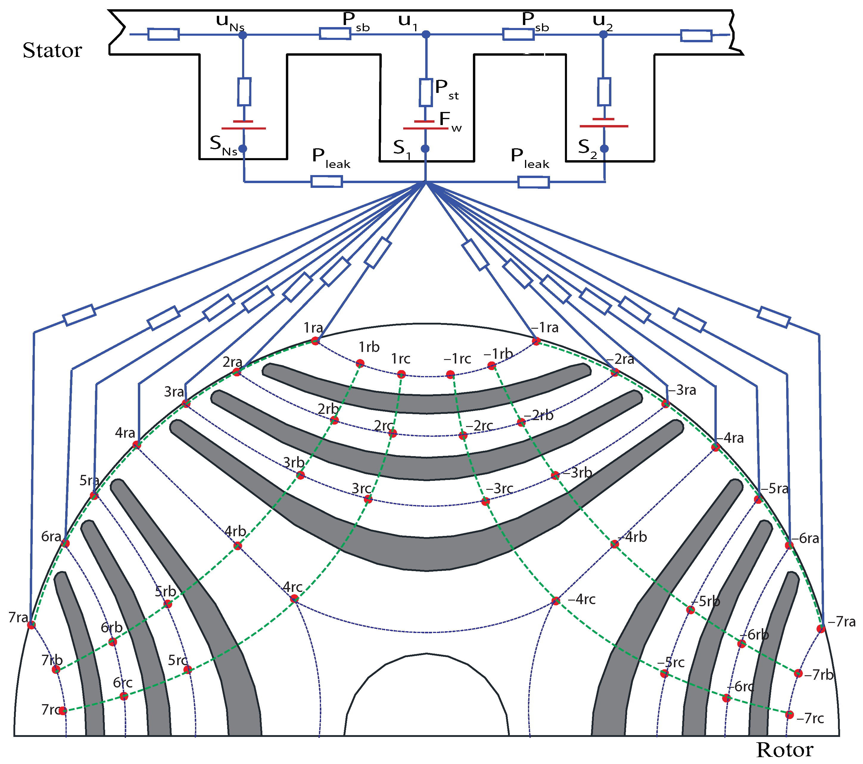
2.2. Magnetic Equivalent Circuit Model of the Stator

Figure 2 shows the MEC model with lumped permeances for a section of SynRM where the variables are defined as follows.
The permeances P s t and P s b model the stator tooth and stator back iron, respectively. The magnetomotive force (MMF) source in each tooth represents equivalent MMF produced by the stator coils under load conditions where
F c o i l = N I
The variable N is the number of turns in the coil and I is the current in the coil. In addition, the slot leakage permeance unit is added between adjacent teeth to calculate leakage flux flowing through the stator slot. Application of KCL to the stator nodes yield the mathematical model for the stator [5,8,45].
At node u N s in Figure 2:
( F u , N s 1 F u , N s ) P s b + ( F u , 1 F u , N s ) P s b + ( F s , N s F u , N s F w , N s ) P s t = 0
This yields N s equations which can be formulated as a matrix equation:
K s b F ¯ u + P s t F ¯ s P s t F ¯ w = 0
where K s b is a N s × N s matrix with stator permeances. The diagonal elements of K s b are the sum of all permeances connected to the corresponding node, e.g., the value at the ith row and ith column represent the sum of elements connected to node i of the stator network. The off-diagonal elements correspond to element between the respective nodes, e.g., the value at the ith row and jth column represent permeance between nodes i and j. The variables F ¯ u and F ¯ s represent the node MMF vectors of the corresponding nodes.

2.3. Magnetic Equivalent Circuit Model of the Rotor

In order to establish an accurate model, the rotor segments are split into flux carrier and flux barriers. As shown in the rotor permeance network in Figure 2, the thick nodes show the interconnection nodes. The nodes denoted with subscript ‘ra’ represent the upper layer while the nodes ‘rb’ and ‘rc’ represent the second and the third layers. The dotted lines connecting any two nodes represent the Permeance of that region. The flux barriers are represented by the permeances interconnecting nodes between each layer e.g., between 1 r b and 2 r b , 2 r b and 3 r b . The flux carriers are represented by interconnecting nodes between each layer, e.g., 2 r a and 2 r b , 2 r b and 2 r c , etc. To develop a mathematical representation of this permeance network, KCL is applied at each node obtain a network of equations. The Layer-a of both halves of the pole can be represented by the equation:
P a g , d i a g + P a F ¯ r a + P a b F ¯ r b + P a g F ¯ s = 0 14 × 1
The matrix P a represents Layer-a of the rotor permeance network. The diagonal elements of P a are equal to the negated sum of the permeances connected to each node in Layer-a and adjacent nodes. The off-diagonal elements correspond to element between the nodes, e.g., ith row and jth columns represent the element between the ith and jth nodes. The matrix P a b represents the interconnecting permeance network between the nodes a and b. The matrix P a g represents the air-gap permeance network where the elements within the matrix at the N x t h row and ith column represents the air-gap permeance value between the N x t h stator tooth and the ith node on the rotor surface.
Similarly, Layer-b and Layer-c of the pole can be represented by Equations (6) and (7), respectively:
P a b F ¯ r a + P b F ¯ r b + P b c F ¯ r c = 0 14 × 1
P b c F ¯ r b + P c F ¯ r c = 0 14 × 1
The variables F ¯ r a , F ¯ r b and F ¯ r c represent the MMF vectors at nodes r a , r b and r c , respectively.
The modeling strategy of the air-gap permeance modelling with respect to the varying rotor position will be discussed in detail in the section below.

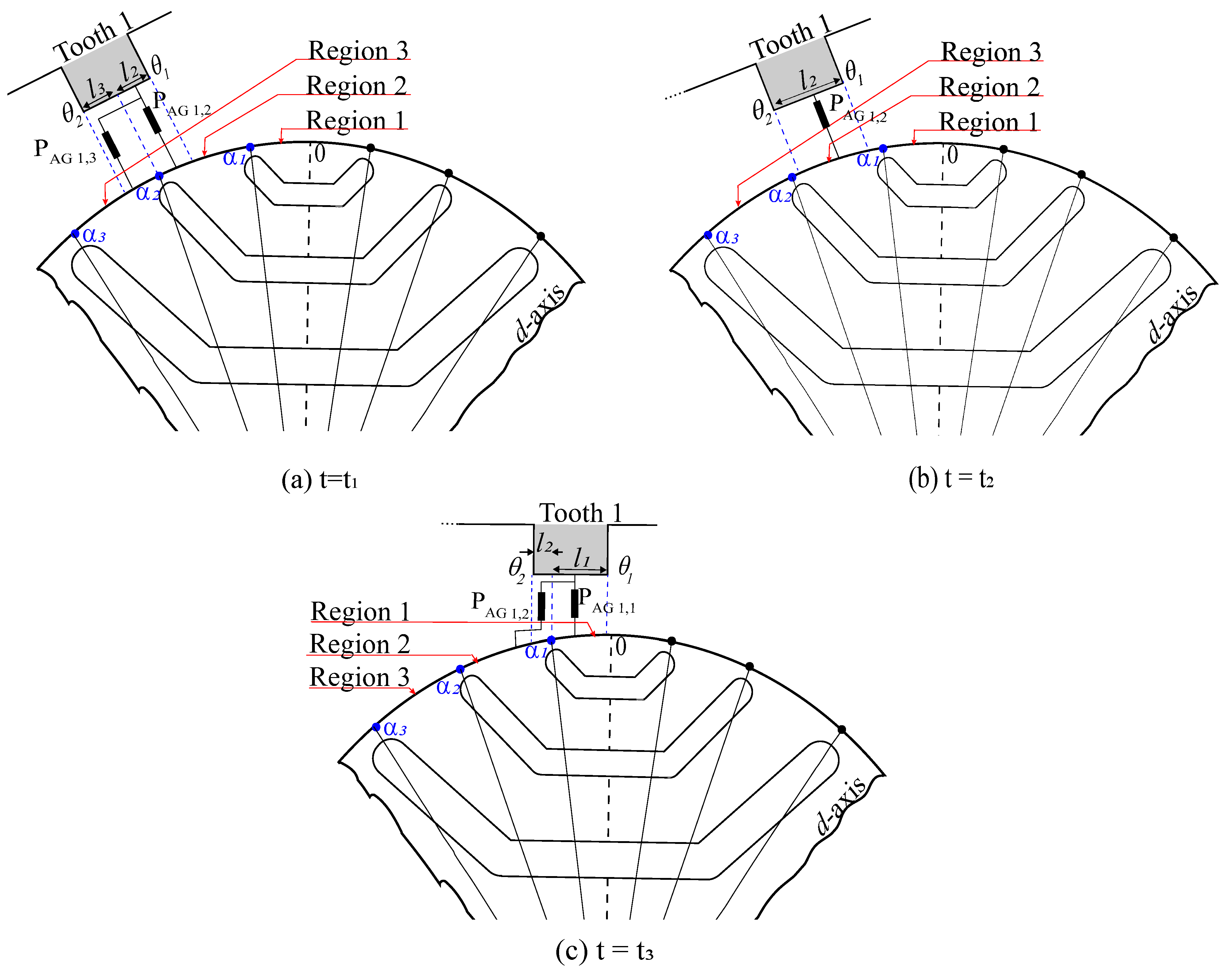
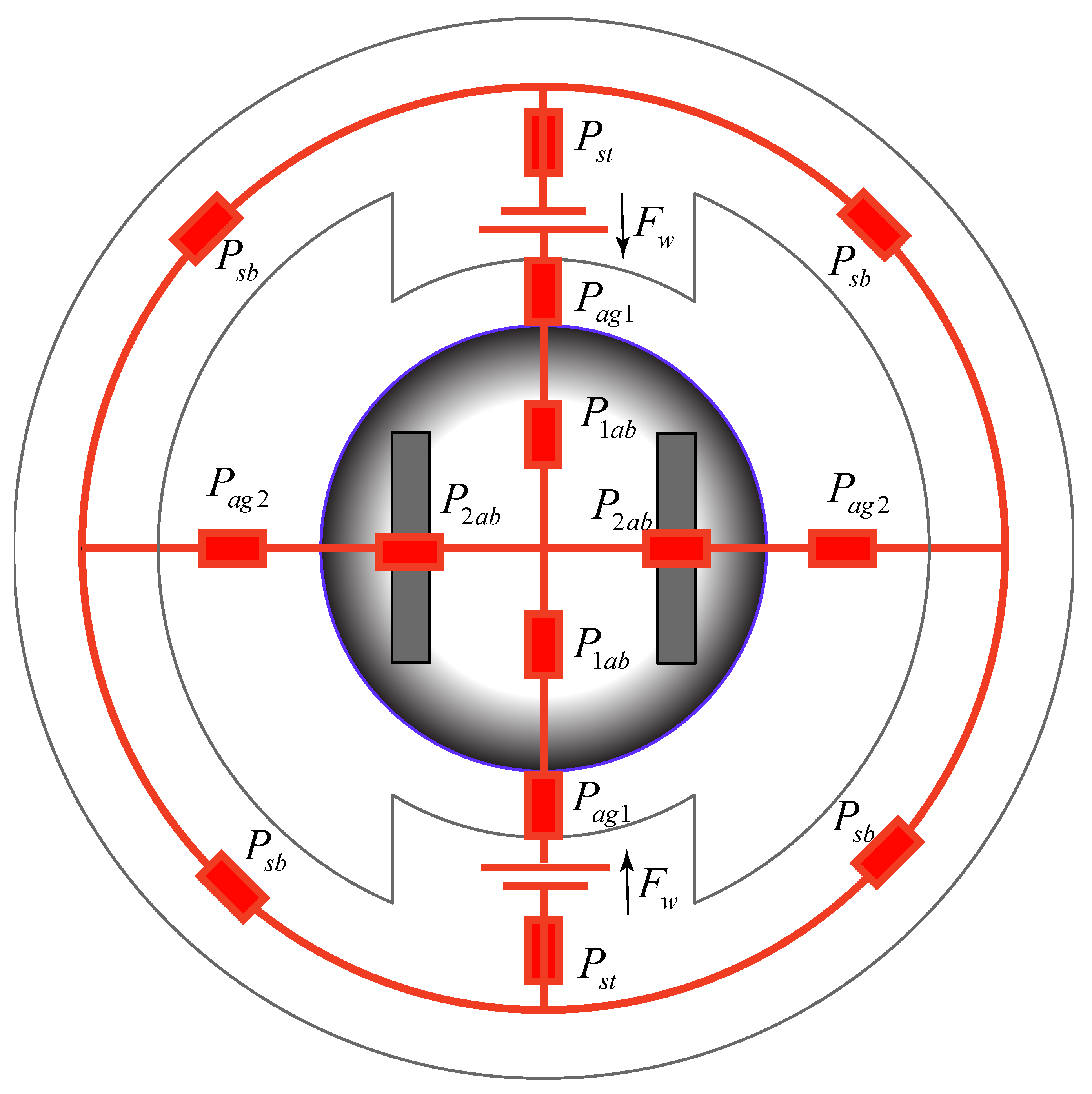
2.4. SynRM Air-Gap Permeance Model

The flux path associated with air-gap have variable dimensions due to a rotational movement of the rotor. Hence, each pole is connected to each tooth via a piecewise continuous permeance varying with rotor position. In this analysis, the rotor surface is divided into multiple regions defined by the flux barrier and their relative positions as shown in Figure 3.
The air-gap permeance linking the N x t h stator tooth with the ith node on the rotor pole is modelled by P A G , N x , i . At each time step, the rotor position changes and the air-gap network has to be recomputed. The analysis of the air-gap permeance at various rotor positions requires the arc length of the overlapping regions between the stator teeth and regions of the rotor that are adjacent to the air-gap [46]. For each stator interconnection node, a logic function described below determines the existence of a connection to one or more rotor surface nodes based on the rotor position.
In Figure 3, “Tooth1” represents any one of the teeth in the stator. The regions 1, 2 and 3 represent three distinct nodes in the rotor. If the angle corresponding to “Tooth1” is [ θ 1 , θ 2 ] and the angle corresponding to the rotor region “i” is [ α i , α i + 1 ] for i = 1, 2, 3, the arc length of the overlapping region l i between “Tooth1” and the rotor region “i” can be calculated by:
l i = 0 if α i + 1 < θ 1 or α i > θ 2 r α i + 1 α i if α i > θ 1 and α i + 1 < θ 2 r α i + 1 θ 1 if α i < θ 1 and θ 1 α i + 1 θ 2 r θ 2 α i if θ 1 α i θ 2 and α i + 1 > θ 2 r θ 2 θ 1 if α i < θ 1 and α i + 1 > θ 2
where r is the mean air-gap radius.
For stator tooth N s at node S N s in Figure 2, KCL can be applied as:
( F ¯ s , N s F ¯ u , N s F ¯ w , N s ) P s t + ( F ¯ s , N s F ¯ s , 1 ) P l e a k + ( F ¯ s , N s F ¯ s , N s 1 ) P l e a k + i = 7 7 ( F ¯ s , N s F ¯ i , r a ) P A G , N s , i = 0
The nodal equations for nodes S 1 to S N s can be represented as:
P s t F ¯ s + P l e a k K F ¯ s P s t F ¯ u P s t F ¯ w + rowsum P a g T F ¯ s P a g T F ¯ r a = 0
where
K = 2 1 0 0 1 1 2 1 0 0 0 1 2 1 0 0 1 0 0 1 2 N s × N s

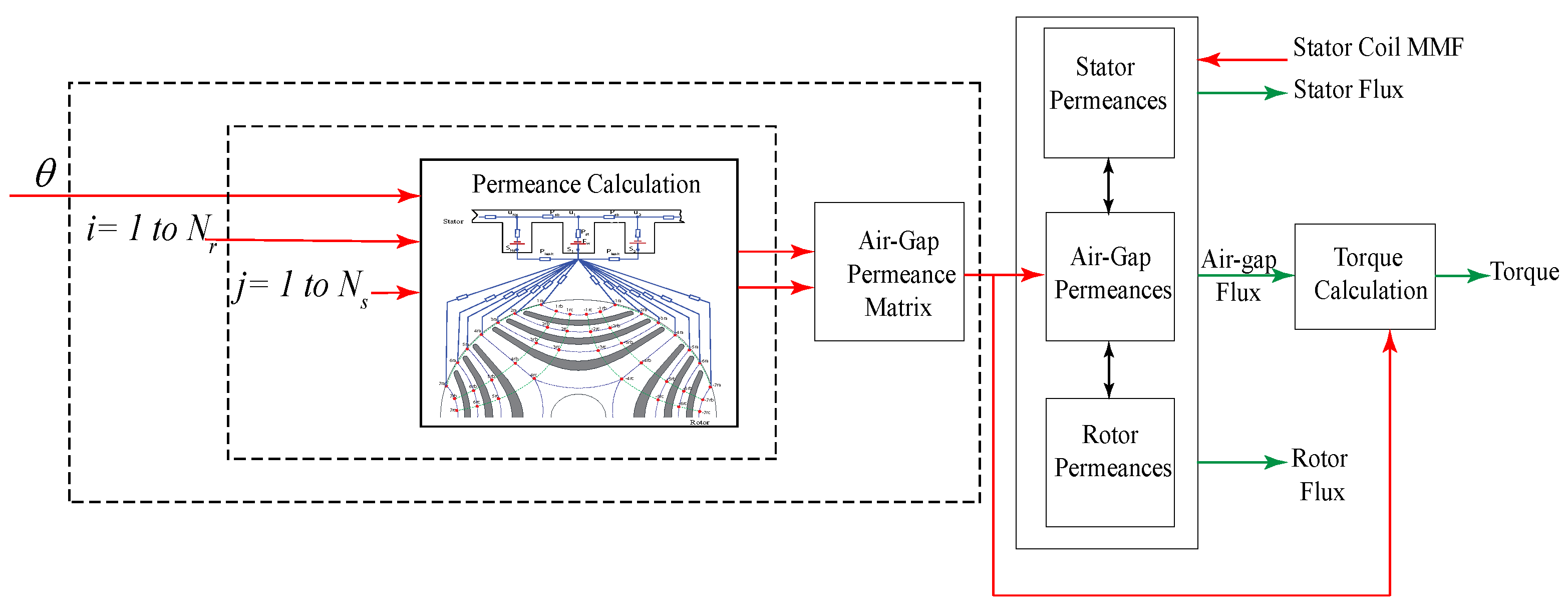
3. Matrix Formulation of the MEC

Following the nodal analysis, the MEC can be described by simultaneous matrix equations formulated as a larger matrix equation:
K s b P s t 0 0 0 0 P a g P a g , d i a g + P a P a b 0 0 0 P a b P b P b c 0 0 0 P b c P c P s t P s t + P l e a k K + r o w s u m P a g T P a g T 0 0 F ¯ u F ¯ s F ¯ r a F ¯ r b F ¯ r c = P s t 0 0 0 P s t F ¯ w

Torque Calculation

The electromagnetic torque produced by the rotor can be written in terms of co-energy as:
T e m = W c θ c o n s t a n t f l u x
Co-energy is expressed as:
W c = F a d ϕ a
F a and ϕ a are the air-gap MMF and flux. The air-gap flux F a can be written as a function of permeance ϕ a :
ϕ a = F a P a
Assuming that the permeances are linear and constant for a given rotor position, co-energy (14) can be expressed as:
W c = 1 2 F a 2 P a
Substitution of (16) in (13) and the resolution of the partial derivative yields:
T e m = 1 2 F a 2 d P a d θ
Using the MEC model T e m can be calculated as the summation of all the torque components produced by each of the air-gap permeances. This is achieved by application of (17) to each of the air-gap elements with rotor position and summation.

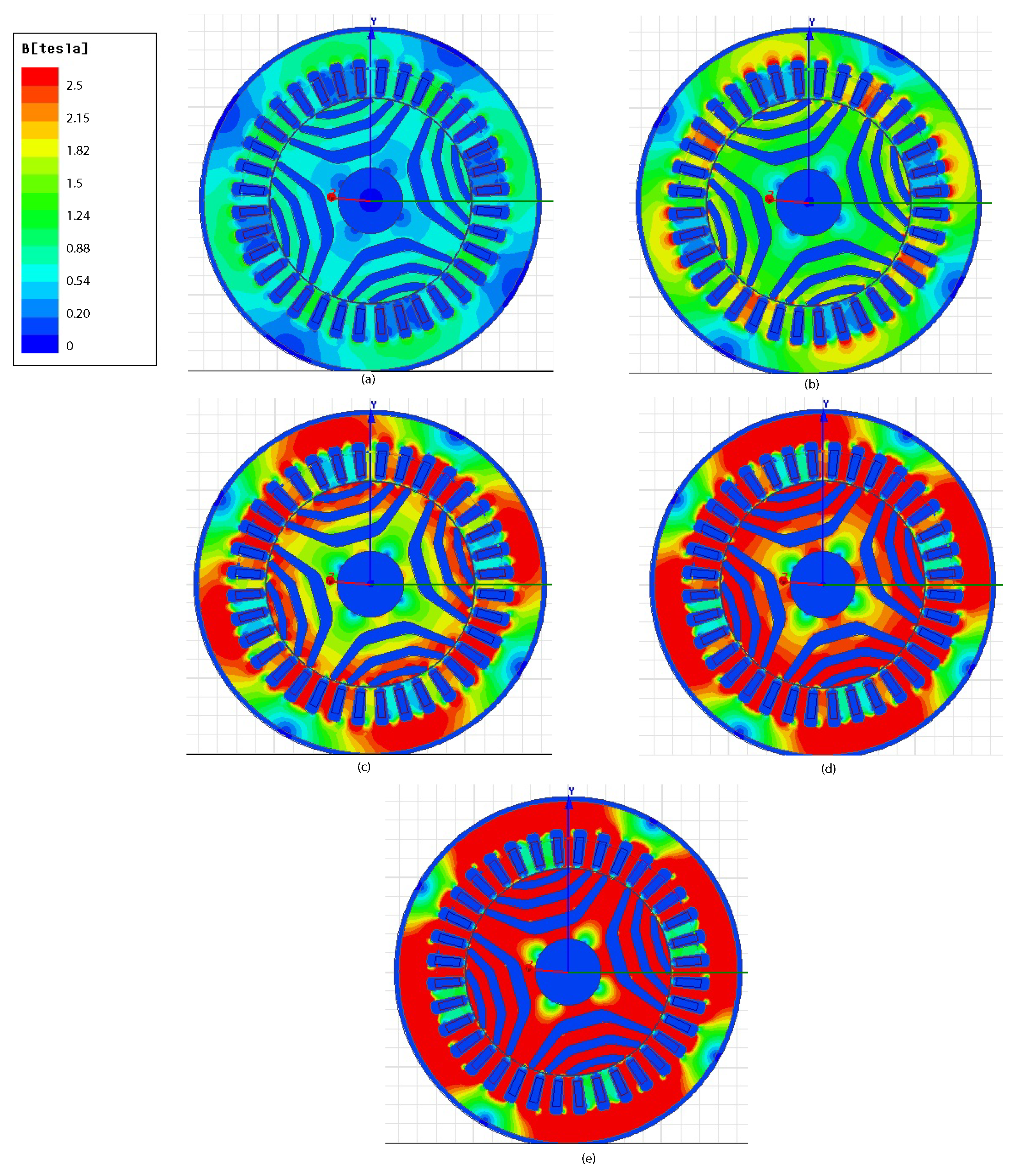
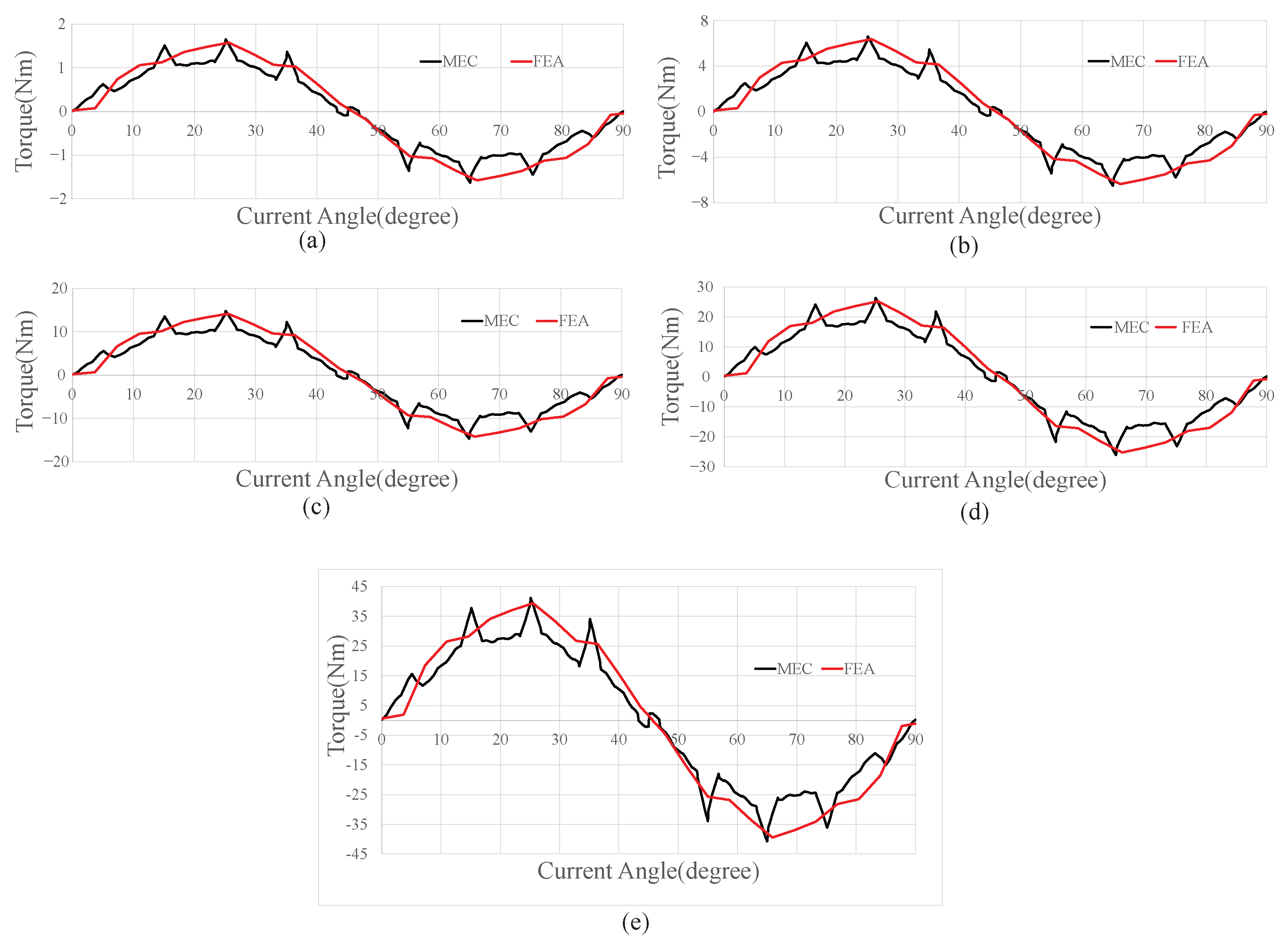
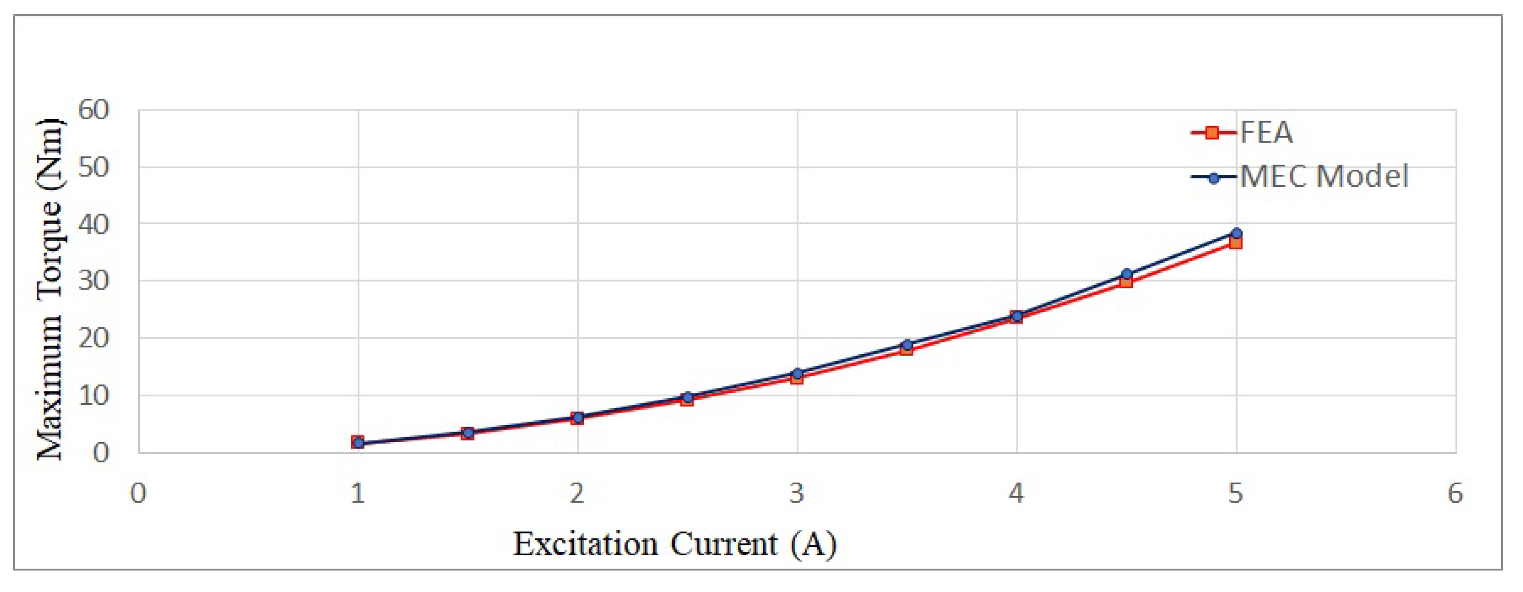
4. Simulation Results

The SynRM machine in Table 2 has been simulated using a time stepped approach, and the results are validated by 2D-FEA using the Ansys-Maxwell Electromagnetic analysis software package. The block diagram representation of the time stepped simulation strategy is depicted in Figure 4.
Owing to the geometry, the air-gap permeance units are symmetrical between the other stator tooth and rotor poles. Thus, air-gap permeances for all possible combinations of stator tooth–rotor poles can be calculated from a single unit model represented by one rotor pole–stator teeth combination. In the simulation strategy shown in Figure 4, the ith rotor pole is used to calculate the air-gap permeances for each relative position with respect to the jth stator tooth. An iterating loop calculates the air-gap permeance parameters for all combinations of rotor pole and stator tooth within each time step. The air-gap permeance matrix hence formed is utilised to solve the full SynRM model for each time step.
FE simulation of the SynRM has been performed in an ANSYS Maxwell Electromagnetic analysis software package. The simulations were run on a 2.5 GHz Intel® Core-i5 machine with a 64-bit operating system and 16 GB of RAM. The MEC method recorded a run time of 52 s with a step size of 0.1 for four cycles of simulation, whereas the same model using FEA took around 9 min for one cycle of simulation. Thus, the developed model could play a vital role in the design stage, where several alternative designs need to be quickly evaluated. The Flux Density distribution in the various stator tooth represented by points A, B, C and D is shown in Figure 5. The flux density obtained from FEA and MEC are compared in Table 3. It can be observed that the flux density predicted using an MEC model are within an acceptable range. Figure 6 shows the flux density distribution in the stator and rotor at rotor position of θ = 61.2 for excitation Current = 1 A, 2 A, 3 A, 4 A and 5 A, respectively. This shows that the machine core is magnetically utilised to its fullest. However, due to the unmodelled saturation effects, an operating flux-density beyond the knee point of the core material needs additional consideration.
Figure 7 shows the SynRM Torque obtained with the MEC model compared to FEA. The torque in the SynRM model for various excitation currents ranging from 1 A to 5 A have been plotted. The result demonstrates that the MEC model is able to predict the instantaneous torque waveform fairly accurately and is a sufficient form to determine the feasibility of a given machine design. The maximum torque developed at different excitation levels predicted with the MEC and FEA is compared in Figure 8, and is also found to achieve a very close match.

5. Conclusions

In this paper, an MEC model for SynRM has been proposed. The main motivation for the proposed modeling approach is to obtain a model that can be applied to any stator teeth/ rotor pole combination. The MEC modelling technique developed in this research is then applied in a time-stepped simulation strategy, and the results are compared with finite element simulation results. Comparisons show that the proposed MEC approach offers good accuracy and is able to predict the characteristics of SynRM motors with reasonable accuracy. The model exhibits promising results to be utilised as a rapid design tool to assess the feasibility of a SynRM design in the machine design process.

Author Contributions

Conceptualization, R.J. and N.F.; methodology, R.J.; software, R.J.; validation, R.J., N.F.; formal analysis, R.J.; investigation, R.J.; resources, R.J.; data curation, R.J.; writing—original draft preparation, R.J.; writing—review and editing, N.F., A.M. and N.U.; supervision, N.F., A.M. and N.U. All authors have read and agreed to the published version of the manuscript.

Funding

This research was funded by the RTP Scholarships supported by the RMIT University and the Commonwealth Government.

Institutional Review Board Statement

Not applicable.

Informed Consent Statement

Not applicable.

Data Availability Statement

Not applicable.

Conflicts of Interest

The authors declare no conflict of interest.

References

  1. Mi, C.; Filippa, M.; Liu, W.; Ma, R. Analytical method for predicting the air-gap flux of interior-type permanent-magnet machines. IEEE Trans. Magn. 2004, 40, 50–58. [Google Scholar] [CrossRef]
  2. Han, S.H.; Jahns, T.M.; Soong, W.L. A Magnetic Circuit Model for an IPM Synchronous Machine Incorporating Moving Airgap and Cross-Coupled Saturation Effects. In Proceedings of the 2007 IEEE International Electric Machines Drives Conference, Antalya, Turkey, 3–5 May 2007; Volume 1, pp. 21–26. [Google Scholar] [CrossRef]
  3. Lovelace, E.; Jahns, T.; Lang, J. A saturating lumped-parameter model for an interior PM synchronous machine. IEEE Trans. Ind. Appl. 2002, 38, 645–650. [Google Scholar] [CrossRef]
  4. Rahman, M.; Little, T.; Slemon, G. Analytical models for interior-type permanent magnet synchronous motors. IEEE Trans. Magn. 1985, 21, 1741–1743. [Google Scholar] [CrossRef]
  5. Ostović, V. Magnetic Equivalent Circuit Presentation of Electric Machines. Electr. Mach. Electromech. 1987, 12, 407–432. [Google Scholar] [CrossRef]
  6. Slemon, G.R. Equivalent circuits for transformers and machines including nonlinear effects. Proc. IEE 1953, 5, 129–143. [Google Scholar] [CrossRef]
  7. Sudhoff, S.D.; Kuhn, B.T.; Corzine, K.A.; Branecky, B.T. Magnetic Equivalent Circuit Modeling of Induction Motors. IEEE Trans. Energy Convers. 2007, 22, 259–270. [Google Scholar] [CrossRef]
  8. Ostovic, V. A Method for Evaluation of Transient and Steady State Performance in Saturated Squirrel Cage Induction Machines. IEEE Trans. Energy Convers. 1986, 3, 190–197. [Google Scholar] [CrossRef]
  9. Fiennes, J. New approach to general theory of electrical machines using magnetic equivalent circuits. Proc. Inst. Electr. Eng. 1973, 120, 94. [Google Scholar] [CrossRef]
  10. Rasmussen, C.; Ritchie, E. A magnetic equivalent circuit approach for predicting PM motor performance. In Proceedings of the IAS’97, Conference Record of the 1997 IEEE Industry Applications Conference Thirty-Second IAS Annual Meeting, New Orleans, LA, USA, 5–9 October 1997; Volume 1, pp. 10–17. [Google Scholar] [CrossRef]
  11. Mao, S.H.; Dorrell, D.; Tsai, M.C. Fast Analytical Determination of Aligned and Unaligned Flux Linkage in Switched Reluctance Motors Based on a Magnetic Circuit Model. IEEE Trans. Magn. 2009, 45, 2935–2942. [Google Scholar] [CrossRef]
  12. Kokernak, J.; Torrey, D. Magnetic circuit model for the mutually coupled switched-reluctance machine. IEEE Trans. Magn. 2000, 36, 500–507. [Google Scholar] [CrossRef]
  13. Amrhein, M.; Krein, P.T. Induction Machine Modeling Approach Based on 3D Magnetic Equivalent Circuit Framework. IEEE Trans. Energy Convers. 2010, 25, 339–347. [Google Scholar] [CrossRef]
  14. Perho, J. Reluctance Network for Analysing Induction Machines; Finnish Academy of Technology: Helsinki, Finland, 2002. [Google Scholar]
  15. Slemon, G. An equivalent circuit approach to analysis of synchronous machines with saliency and saturation. IEEE Trans. Energy Convers. 1990, 5, 538–545. [Google Scholar] [CrossRef]
  16. Xiao, Y.; Slemon, G.; Iravani, M. Implementation of an equivalent circuit approach to the analysis of synchronous machines. IEEE Trans. Energy Convers. 1994, 9, 717–723. [Google Scholar] [CrossRef]
  17. Vlado, O. Dynamics of Saturated Electric Machines; Springer: Berlin/Heidelberg, Germany, 1989. [Google Scholar]
  18. Bradley, K.; Tami, A. Reluctance mesh modelling of induction motors with healthy and faulty rotors. In Proceedings of the IAS’96, Conference Record of the 1996 IEEE Industry Applications Conference Thirty-First IAS Annual Meeting, San Diego, CA, USA, 6–10 October 1996; Volume 1, pp. 625–632. [Google Scholar] [CrossRef]
  19. Carpenter, M.; Macdonald, D. Circuit representation of inverter-fed synchronous motors. IEEE Trans. Energy Convers. 1989, 4, 531–537. [Google Scholar] [CrossRef] [Green Version]
  20. Bianchi, N.; Bolognani, S.; Bon, D.; Dai Pre, M. Rotor Flux-Barrier Design for Torque Ripple Reduction in Synchronous Reluctance and PM-Assisted Synchronous Reluctance Motors. IEEE Trans. Ind. Appl. 2009, 45, 921–928. [Google Scholar] [CrossRef]
  21. Barcaro, M.; Bianchi, N. Air-Gap Flux Density Distortion and Iron Losses in Anisotropic Synchronous Motors. IEEE Trans. Magn. 2010, 46, 121–126. [Google Scholar] [CrossRef]
  22. Horvath, D.C.; Pekarek, S.D.; Sudhoff, S.D. A Scaled Mesh/Nodal Formulation of Magnetic Equivalent Circuits with Motion. IEEE Trans. Energy Convers. 2019, 34, 58–69. [Google Scholar] [CrossRef]
  23. Derbas, H.W.; Williams, J.M.; Koenig, A.C.; Pekarek, S.D. A Comparison of Nodal- and Mesh-Based Magnetic Equivalent Circuit Models. IEEE Trans. Energy Convers. 2009, 24, 388–396. [Google Scholar] [CrossRef] [Green Version]
  24. Law, J.; Busch, T.; Lipo, T. Magnetic circuit modelling of the field regulated reluctance machine. Part I: Model development. IEEE Trans. Energy Convers. 1996, 11, 49–55. [Google Scholar] [CrossRef]
  25. Busch, T.; Law, J.; Lipo, T. Magnetic circuit modeling of the field regulated reluctance machine. Part II: Saturation modeling and results. IEEE Trans. Energy Convers. 1996, 11, 56–61. [Google Scholar] [CrossRef]
  26. Delale, A.; Albert, L.; Gerbaud, L.; Wurtz, F. Automatic generation of sizing models for the optimization of electromagnetic devices using reluctance networks. IEEE Trans. Magn. 2004, 40, 830–833. [Google Scholar] [CrossRef]
  27. Turowski, J.; Turowski, M.; Kopec, M. Method of three-dimensional network solution of leakage field of three-phase transformers. IEEE Trans. Magn. 1990, 26, 2911–2919. [Google Scholar] [CrossRef]
  28. Gyselinck, J.; Vandevelde, L.; Melkebeek, J. 2D FE Models, Magnetic Circuits and Their Coupling Applied to the Dynamic Analysis of Induction Machines. In Proceedings of the 4th International Workshop on Electric and Magnetic Fields, Marseille, France, 12–15 May 1998; pp. 469–474. [Google Scholar]
  29. Mariani, G.B.; Besri, A.; Voyer, N.; Chillet, C.; Fassenet, M.; Garbuio, L. Synchronous reluctance motor multi-static MEC model. In Proceedings of the IECON 2015—41st Annual Conference of the IEEE Industrial Electronics Society, Yokohama, Japan, 9–12 November 2015. [Google Scholar] [CrossRef]
  30. Peng, W.; Gyselinck, J.; Dziechciarz, A.; Martis, C. Magnetic equivalent circuit modelling of Reluctance Machines. In Proceedings of the 2016 Eleventh International Conference on Ecological Vehicles and Renewable Energies (EVER), Monte Carlo, Monaco, 6–8 April 2016. [Google Scholar] [CrossRef]
  31. Dziechciarz, A.; Martis, C. Magnetic equivalent circuit of synchronous reluctance machine. In Proceedings of the 2016 ELEKTRO, Strbske Pleso, Slovakia, 16–18 May 2016. [Google Scholar] [CrossRef]
  32. Hubert, T.; Steckel, R.; Reinlein, M.; Kremser, A.; Herzog, H.G. Nonlinear reluctance network method for synchronous reluctance machine analysis. In Proceedings of the 2015 18th International Conference on Electrical Machines and Systems (ICEMS), Pattaya, Thailand, 25–28 October 2015. [Google Scholar] [CrossRef]
  33. Elloumi, D.; Ibala, A.; Rebhi, R.; Masmoudi, A. Lumped Circuit Accounting for the Rotor Motion Dedicated to the Investigation of the Time-Varying Features of Claw Pole Topologies. IEEE Trans. Magn. 2015, 51, 1–8. [Google Scholar] [CrossRef]
  34. Tessarolo, A.; Degano, M.; Bianchi, N. On the analytical estimation of the airgap field in synchronous reluctance machine. In Proceedings of the 2014 International Conference on Electrical Machines (ICEM), Berlin, Germany, 2–5 September 2014; pp. 239–244. [Google Scholar] [CrossRef]
  35. Tessarolo, A. Modeling and Analysis of Synchronous Reluctance Machines With Circular Flux Barriers Through Conformal Mapping. IEEE Trans. Magn. 2015, 51, 8104411. [Google Scholar] [CrossRef]
  36. López-Torres, C.; Garcia Espinosa, A.; Riba, J.R.; Romeral, L. Design and Optimization for Vehicle Driving Cycle of Rare-Earth-Free SynRM Based on Coupled Lumped Thermal and Magnetic Networks. IEEE Trans. Veh. Technol. 2018, 67, 196–205. [Google Scholar] [CrossRef]
  37. Heidari, H.; Andriushchenko, E.; Rassõlkin, A.; Kallaste, A.; Vaimann, T.; Demidova, G.L. Comparison of Synchronous Reluctance Machine and Permanent Magnet-Assisted Synchronous Reluctance Machine Performance Characteristics. In Proceedings of the 2020 27th International Workshop on Electric Drives: MPEI Department of Electric Drives 90th Anniversary (IWED), Moscow, Russia, 27–30 January 2020; pp. 1–5. [Google Scholar] [CrossRef]
  38. Neumann, J.; Hénaux, C.; Fadel, M.; Prieto, D.; Fournier, E.; Yamdeu, M.T. Improved dq model and analytical parameters determination of a Permanent Magnet Assisted Synchronous Reluctance Motor (PMa-SynRM) under saturation using Frozen Permeability Method. In Proceedings of the 2020 International Conference on Electrical Machines (ICEM), Gothenburg, Sweden, 23–26 August 2020; Volume 1, pp. 481–487. [Google Scholar] [CrossRef]
  39. Maroufian, S.S.; Pillay, P. Torque Characterization of a Synchronous Reluctance Machine Using an Analytical Model. IEEE Trans. Transp. Electrif. 2018, 4, 506–516. [Google Scholar] [CrossRef]
  40. Bianchi, N.; Bolognani, S.; Bon, D.; Pre, M. Rotor flux-barrier design for torque ripple reduction in synchronous reluctance motors. In Proceedings of the Conference Record of the 2006 IEEE Industry Applications Conference Forty-First IAS Annual Meeting, Tampa, FL, USA, 8–12 October 2006; Volume 3, pp. 1193–1200. [Google Scholar] [CrossRef]
  41. Spargo, C.M.; Mecrow, B.C.; Widmer, J.D. A Seminumerical Finite-Element Postprocessing Torque Ripple Analysis Technique for Synchronous Electric Machines Utilizing the Air-Gap Maxwell Stress Tensor. IEEE Trans. Magn. 2014, 50, 1–9. [Google Scholar] [CrossRef] [Green Version]
  42. Mahmoud, H.; Bacco, G.; Degano, M.; Bianchi, N.; Gerada, C. Synchronous Reluctance Motor Iron Losses: Considering Machine Nonlinearity at MTPA, FW, and MTPV Operating Conditions. IEEE Trans. Energy Convers. 2018, 33, 1402–1410. [Google Scholar] [CrossRef]
  43. Bacco, G.; Bianchi, N.; Mahmoud, H. A Nonlinear Analytical Model for the Rapid Prediction of the Torque of Synchronous Reluctance Machines. IEEE Trans. Energy Convers. 2018, 33, 1539–1546. [Google Scholar] [CrossRef]
  44. Zhang, G.; Tao, J.; Li, Y.; Hua, W.; Xu, X.; Chen, Z. Magnetic Equivalent Circuit and Optimization Method of a Synchronous Reluctance Motor with Concentrated Windings. Energies 2022, 15, 1735. [Google Scholar] [CrossRef]
  45. Ostovic, V. A novel method for evaluation of transient states in saturated electric machines. IEEE Trans. Ind. Appl. 1989, 25, 96–100. [Google Scholar] [CrossRef]
  46. Guo, L.; Xia, C.; Wang, H.; Wang, Z.; Shi, T. Improved equivalent magnetic network modeling for analyzing working points of PMs in interior permanent magnet machine. J. Magn. Magn. Mater. 2018, 454, 39–50. [Google Scholar] [CrossRef]
Figure 1. SynRM fundamental MEC unit model for single pole pair.
Energies 15 04422 g001
Figure 2. MEC model for a section of Stator, Rotor and Air-Gap of SynRM.
Energies 15 04422 g002
Figure 3. Variation of the air-gap permeance model with rotor position and relationship with different regions.
Energies 15 04422 g003
Figure 4. Block diagram representation of the time stepped simulation technique.
Energies 15 04422 g004
Figure 5. Flux Density Distribution Plot from FEA for rotor positions (a) θ = 7.2 ; (b) θ = 18 (c) θ = 25 .
Energies 15 04422 g005
Figure 6. Flux Density Distribution Plot from FEA for rotor position θ = 61.2 for excitation current (a) 1 A, (b) 2 A, (c) 3 A, (d) 4 A and (e) 5 A respectively.
Energies 15 04422 g006
Figure 7. Torque Plot vs. Current angle for (a) 1 A; (b) 2 A; (c) 3 A; (d) 4 A (e) 5 A excitation (No. of Turns = 100).
Energies 15 04422 g007
Figure 8. Excitation vs. Maximum Torque plot.
Energies 15 04422 g008
Table 1. Nomenclature and definition of variables.
F ¯ u Magnetic Potential vector at nodes ‘u
F ¯ s Magnetic Potential vector at nodes ‘s
F ¯ w Magneto motive force vector
F ¯ r a Magnetic Potential vector at nodes ‘ra
F ¯ r b Magnetic Potential vector at nodes ‘rb
F ¯ r c Magnetic Potential vector at nodes ‘rc
P s t Stator tooth permeance
P s b Stator back iron permeance
P l e a k Stator outer leakage permeance
MECMagnetic Equivalent Circuit
Table 2. SynRM parameters.
ParameterValue
Flux-barrier/pole3
Rotor shaft diameter35 mm
Air-gap length0.3 mm
Axial length140 mm
Rated Current Density10 A/m 2
Number of turns100
Number of phases3
Rated frequency200 Hz
Number of stator slots/poles36/4
Stator outer/inner diameter180/110 mm
Rotor outer diameter109.4 mm
Material typeiron (ideal)
Material relative permeability4000
Table 3. Stator tooth flux density comparison.
θ = 7.2° θ = 18° θ = 25°
FEA MEC FEA MEC FEA MEC
A0.4210.4480.4570.4060.2110.37
B0.3830.3730.40.3780.580.42
C0.7740.800.8330.8320.7910.81
D0.560.4960.590.510.650.51
Publisher’s Note: MDPI stays neutral with regard to jurisdictional claims in published maps and institutional affiliations.

