Article

Heat Transfer Augmentation and Friction Factor Due to the Arrangement of Rectangular Turbulators in a Finned Air Channel of a Solar Air Heater

1
Graduate School of Refrigeration and Air-Conditioning Engineering, Pukyong National University, Busan 48513, Republic of Korea
2
Department of Refrigeration and Air-Conditioning Engineering, Pukyong National University, Busan 48513, Republic of Korea
3
Industry-University Cooperation Foundation, Pukyong National University, Busan 48513, Republic of Korea
*
Author to whom correspondence should be addressed.
Energies 2023, 16(19), 6891; https://doi.org/10.3390/en16196891
Submission received: 4 September 2023 / Revised: 20 September 2023 / Accepted: 28 September 2023 / Published: 29 September 2023

Abstract

:
In this study, the heat transfer augmentation and friction factor of a novel type of solar air heater (SAH), which incorporates longitudinal fins and rectangular turbulators, were investigated numerically with different arrangements of the turbulators. The effects of arrangements of rectangular turbulators placed in a finned air channel on its heat transfer augmentation and friction factor are discussed for Reynolds numbers ranging from 3000 to 15,000 using commercial ANSYS 17.2 software. Four different arrangements are investigated, including Array A, which places turbulators on both the fin’s side and base surfaces at the same position; Array B, where turbulators are sequentially placed on the fin’s side and base surfaces; Array C, where turbulators are only placed on the side surface; and Array D, where turbulators are placed only on the base surface. Array A showed the highest heat transfer augmentation and friction factor among the investigated arrangements. However, the highest thermo-hydraulic performance (THP), considering both the heat transfer augmentation and friction factor, was obtained in Array B, with a value of 1.36. Consequently, Array B was regarded as the most appropriate and effective arrangement method for the finned air channel of a SAH.

Graphical Abstract

1. Introduction

As a source of renewable energy, solar air heaters (SAH) have the ability to transform incoming solar radiation into usable heat without causing any environmental harm. A number of applications are possible with SAH, including the heating of buildings, the drying of fruit and crops, the curing of industrial goods, and the seasoning of wood. In addition, its simple design provides some merits, such as low manufacturing cost and minimal required maintenance [1]. However, a major drawback of SAHs is their low thermal efficiency, which is a consequence of the low thermal conductivity of air [2]. Therefore, many researchers have attempted to increase the heat transfer from the absorber plate of an SAH to the flowing fluid.
Installing turbulators, such as rib, baffle, and protrusion at the heated wall, is one of the most effective techniques to augment the SAH’s thermal performance. Turbulators disrupt the thermal boundary layer, which functions as an obstruction to the heat flow, and generates turbulence adjacent to the heated wall. In this way, heat is able to flow more efficiently from the absorber to the air, leading to an augmentation of heat transfer [3]. So far, many researchers have investigated the augmentation in heat transfer performance and friction penalty in SAHs with various turbulators. Yadav and Bhagoria [4,5,6] evaluated the heat transfer augmentation and friction penalty caused by the circular rib, square rib, and triangular rib and showed that the presence of the rib can boost the heat flow from the absorber plate to the flowing air effectively in SAH. Gawande et al. [7] confirmed the impact of a reverse L-shaped transverse rib on the heat transfer improvement in an SAH. This study reported that the addition of the proposed rib provided 2827 times higher heat transfer compared to the case without it. Kumar and Verma [8] investigated heat transfer enhancement by the transverse sinusoidal rib and found that a maximum improvement of 2.48 times in Nusselt number could be achieved while the maximum increase ratio of pressure drop was 1.76 among the investigated conditions. Kumar et al. [9,10] evaluated the influence of a chamfered rectangular rib and square rib installed in a triangular duct SAH on heat transfer enhancement with various geometric conditions. These studies found that the installation of ribs could effectively boost the heat transfer performance in a triangular duct. Kumar and Goel [11] discussed the influence of the turbulator’s shape on the heat transfer characteristic and fluid flow behavior in an SAH coupled with a triangular air duct. They reported that a forward-chamfered rectangular turbulator performed better than other ribs. Pandey et al. [12] employed multiple arcs with a gap as turbulator, and the greatest increment in heat transfer and friction factor achieved by this kind of turbulator were reported to be 5.85 and 4.96, respectively. Singh et al. [13] compared square wave ribs and multiple broken ribs, and showed that the multiple broken ribs had superior heat transfer and lower friction penalty in comparison to the square wave ribs. Thao et al. [14] conducted a numerical investigation of an SAH coupled with inclined baffles and optimized the installation conditions of the baffles using the Taguchi method. Bhuvad et al. [15] proposed a novel type of absorber plate roughened with apex-up discrete arc ribs, and compared the thermal performance achieved by the proposed ribs with those of the existing apex-down ribs. Their research concluded that the proposed apex-up ribs provided better thermal performance than the conventional apex-down ribs. Including these studies, various types of turbulator, such as rectangular rib [16], wedge-shaped rib [17], hyperbolic [18], multi-staggered W-shape rib [19], quarter-circular rib [20], sinusoidal protrusion [21], Multi-V rib [22], discrete multiple inclined baffle [23], and conical protrusion have been investigated so far, and more detailed information can be found in relevant review articles [2,3,24].
Another method to augment the SAH’s thermal efficiency is extending the area of heat transfer. Pakdaman et al. [25] assessed the thermal performance of an SAH incorporating a longitudinal rectangular fin under natural convection conditions and reported that integrating the fin could achieve a heat transfer enhancement of about 20%. Fudholi et al. [26] evaluated the performance and cost-effectiveness of a double-pass SAH with longitudinal fins. This research found that the double-pass SAH with fins offers better performance and is more efficient for a given cost than the double-pass SAH without fins. Priyam and Chand [27,28] assessed the performance of an SAH equipped with wavy fins and reported that the wavy fin improved the thermal performance by 29.39% to 62.53%. Bhattacharyya et al. [29] established a mathematical model of the SAH with an extruded finned absorber plate for drying applications. They demonstrated that the outlet air temperature increased and then declined as the number of installed fins increased while the pressure drop continued to increase. The optimum installation number of fins and fin thickness for their SAH were proposed as 80 fins and 2 mm, respectively. Kabeel et al. [30] evaluated the daily efficiency of an SAH coupled with three different fin heights and showed that a higher fin height enhanced daily efficiency. Saravanan et al. [31] compared the SAH with C-shaped perforated fins to that of an SAH with C-shaped non-perforated fins. This study found that a C-shaped perforated fin provided a superior Nusselt number and a smaller friction factor than a non-perforated fin. Chand et al. [32] examined the performance of an SAH paired with louvered fins at various fin spacings with differing air flow rates. In their research, the SAH with louvered fins demonstrated 59.45% to 106.7% higher thermal efficiency than a conventional SAH. Karwa [33] proposed an SAH that had multiple rectangular air channels formed by longitudinal fins and reported that the proposed SAH produced approximately 28–31% more thermal energy than the conventional SAH at the same blowing power. Nagaraj et el. [34] experimentally and numerically examined the performance of the double-pass SAH with aerofoil fins introduced in the air channel, and reported that an increase of 23.24% in thermal efficiency could be achieved by the proposed fin.
The above review of the literature reveals that the SAH generally has adapted either turbulators or fins to improve its thermal performance. The performance improvement of the SAH by the turbulators or fins has been individually conducted. However, the turbulator and the fin serve different purposes in the SAH: the turbulator enhances the heat transfer coefficient, while the fin extends the area of heat transfer. Thus, by combining a turbulator and a fin, the heat transfer coefficient can be boosted and the area of heat transfer can be expanded. However, there are very limited studies that explain heat transfer augmentation and friction penalty within an SAH that incorporates a fin and a turbulator. Moreover, heat transfer in an SAH with a longitudinal fin occurs on both the base and side surfaces, distinguishing it from previously studied SAHs. Therefore, finding the proper arrangement of turbulators for a finned air channel is important. However, to the authors’ knowledge, there is no study that reveals how different arrangements of the turbulators affect the heat transfer augmentation and friction factor in a finned air channel of an SAH, and this research gap motivated the authors to conduct this study.
In this study, the heat transfer augmentation and friction factor in a finned air channel incorporating a turbulator are investigated with various arrangements through computational fluid dynamics (CFD) analysis. A rectangular turbulator with a simple shape was chosen as a turbulator. The current investigation is conducted under four different arrangements. The effects of these different arrangements on the augmentation in heat transfer and the enhancement in friction factor are discussed in detail. Furthermore, the thermo-hydraulic performance (THP) that simultaneously incorporates the heat transfer augmentation and enhancement in the friction factor is evaluated for each arrangement. The main objective of this study is to reveal how different arrangements of the turbulators in a finned air channel of an SAH result in different heat transfer augmentation and friction penalties and to find which arrangement is the most effective for the finned air channel of an SAH.

2. Methodology

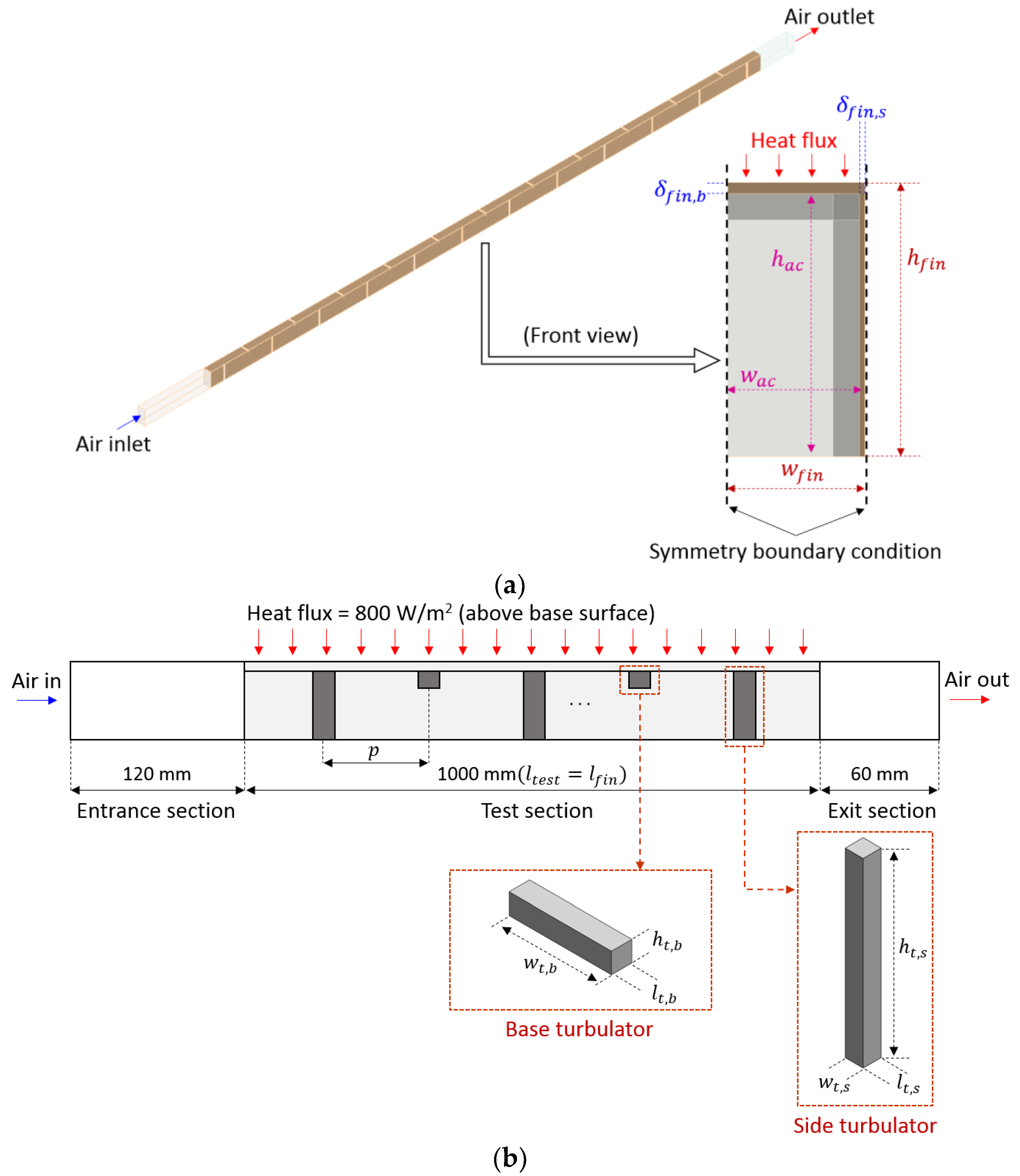
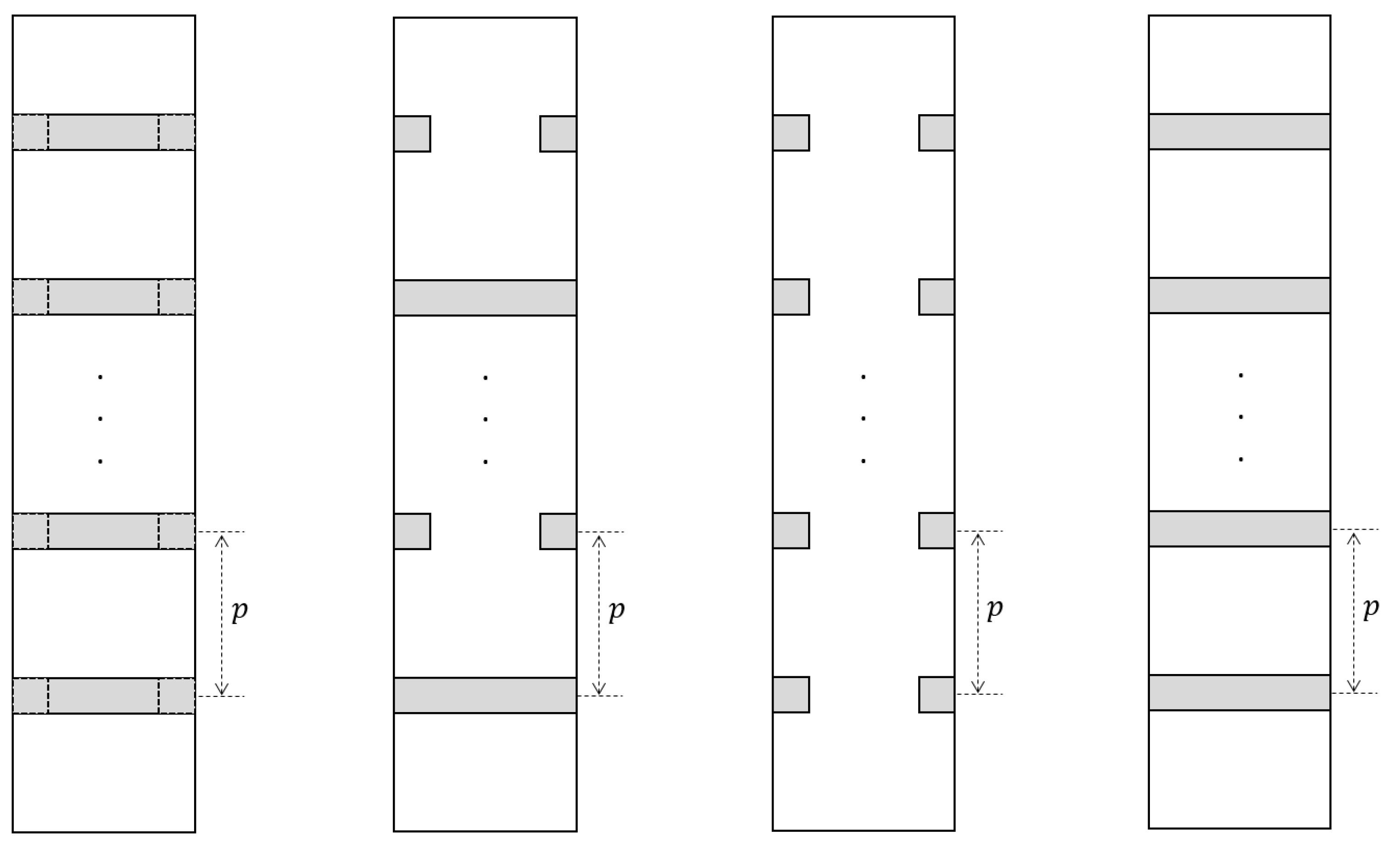
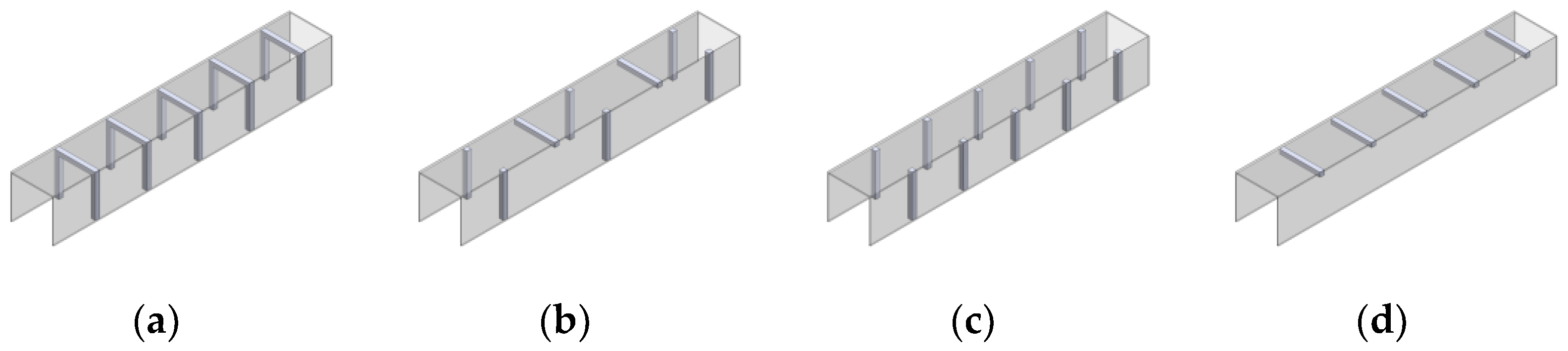
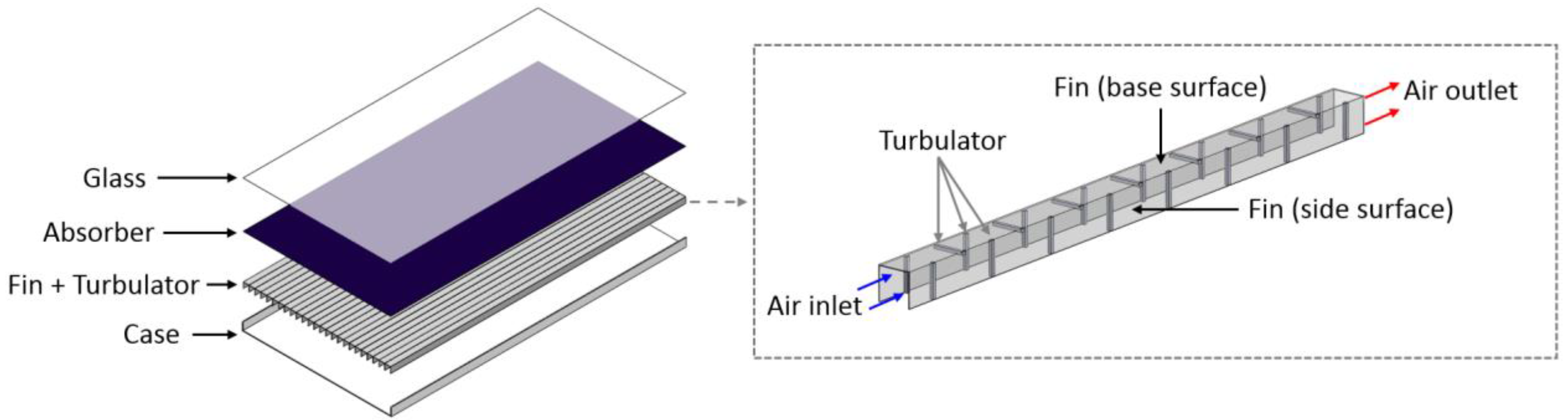
2.1. 3D Model Description

In this study, a CFD simulation of an SAH incorporating fin and rectangular turbulator has been conducted using commercial software (ANSYS Fluent 17.2). Figure 1 shows the schematic of the SAH investigated in this study. The fin’s base surface contacts with the absorber, and the turbulators are placed on the fin’s base and side surfaces.
This study aims to assess the influence of the turbulator arrangement on the heat transfer augmentation and friction factor. Thus, one of the many air channels formed by the fins was chosen as the computational domain for CFD analysis. Figure 2 shows the computational domain examined in this study. With the aim of reducing the computational domain, the symmetry boundary conditions were applied to both the fin’s side surface and the middle of the air channel. A computational domain is composed of three regions: an entrance region, a test region, and an exit region. The length was set at 120 mm for the entrance region, 1000 mm for the test region, and 60 mm for the exit region. In the computational domain, the fin’s height ( h f i n ) , width ( w f i n ), length ( l f i n ), and base surface thickness ( δ f i n ,   b ) were 25 mm, 12.5 mm, 1000 mm, and 1 mm, respectively. The fin’s side surface thickness ( δ f i n ,   s ) was set at 0.5 mm because of the symmetric condition. The air channel’s height ( h a c ) and width ( w a c ) were 24 mm and 12 mm, respectively. The turbulator installed on the side surface had dimensions of 24 mm in height ( h t , s ), 2.4 mm in width ( w t , s ), and 2.4 mm in length ( l t , s ). For the turbulator installed on the base surface, The height ( h t , b ), width ( w t , b ), and length ( l t , b ) were 2.4 mm, 12 mm, and 2.4 mm, respectively. In the actual system, the side and base turbulators have identical geometric conditions; the only difference is the installation direction. Table 1 summarizes the geometrical parameters used in the present investigation.
Figure 3 shows the arrangements of the rectangular turbulator investigated in this study. In Array A, the turbulators are installed on both the fin’s side and base surfaces at the same position with a pitch of 43.2 mm. Therefore, the side and base turbulators are overlapped in this arrangement. In Array B, rectangular turbulators are placed sequentially on the side and base surfaces in the direction of the airflow. The pitch of the installed turbulators remains the same at 43.2 mm. Thus, the total number of installed turbulators in Array B is lower than in Array A. In Array C, the turbulator is located only on the side surface of the fin with a pitch of 43.2 mm. Thus, the number of turbulators in Array C is higher than in Array B. Array D has a turbulator only on the base surface of the fin with a pitch of 43.2 mm. Therefore, Array D has the lowest number of turbulators in a finned air channel. For all arrangements, heat transfer augmentation and friction penalty were evaluated with five different Reynolds numbers ranging from 3000 to 15,000.

2.2. Governing Equations

The flow of air in a finned air channel of an SAH is characterized by turbulent and steady-state incompressible flow, and this flow field is governed by the continuity, momentum, and energy equations. Considering the steady-state incompressible turbulence flow, these governing equations can be written as follows [9,35,36]:
Continuity:
u j x j = 0
Momentum:
ρ u i u j x j = p x i + x j μ u i x j + u j x i + x j μ t u i x j + u j x i
Energy:
  ρ u i T x i = x j μ P r + μ t P r T x j
where the μ and μ t represent viscosity and turbulent viscosity, respectively.
This SST k - ω model was employed in this study to model the turbulent behavior in a fluid field. The transport equations for the SST k - ω model are as follows [36,37,38]:
ρ k u i x i = x j Γ k k x j + G k Y k + S k
and
ρ ω u j x i = x i Γ ω ω x j + G ω Y ω + S ω
where the k is turbulence kinetic energy, ω is specific dissipation rate. The G k and G ω are the production of turbulence kinetic energy and generation of ω . The Γ k and Y k represent effective diffusivity and dissipation of k , while Γ ω and Y ω represent the same parameters for ω . The S k and S ω are user-defined sorce terms. The solution method is described in Section 2.3, and further information on the above equations can be found in Ref. [36].

2.3. Boundary Condition and Solution Method

Table 2 lists boundary conditions employed in the current investigation. As mentioned in the previous sub-section, a symmetric boundary condition has been implemented in both the middle of the air flow channel and the side surface of the fin. The fin’s base surface was imposed with a uniform heat flux, while the remaining walls were considered adiabatic walls. The inlet and outlet boundary conditions were assigned with fixed velocity and pressure conditions, respectively.
The computational domain was solved using the commercial code of ANSYS Fluent 17.2. The governing equations for the continuity, momentum, energy, and turbulence model under the incompressible and steady-state flow were solved, employing the aforementioned boundary conditions. The coupled algorithm was employed to link the velocity and pressure field. For discretizing the governing equations, the second-order upwind scheme was selected. In the energy equation, a convergence criteria of 10−6 was used, while a convergence criteria of 10−5 was set for the other equations.

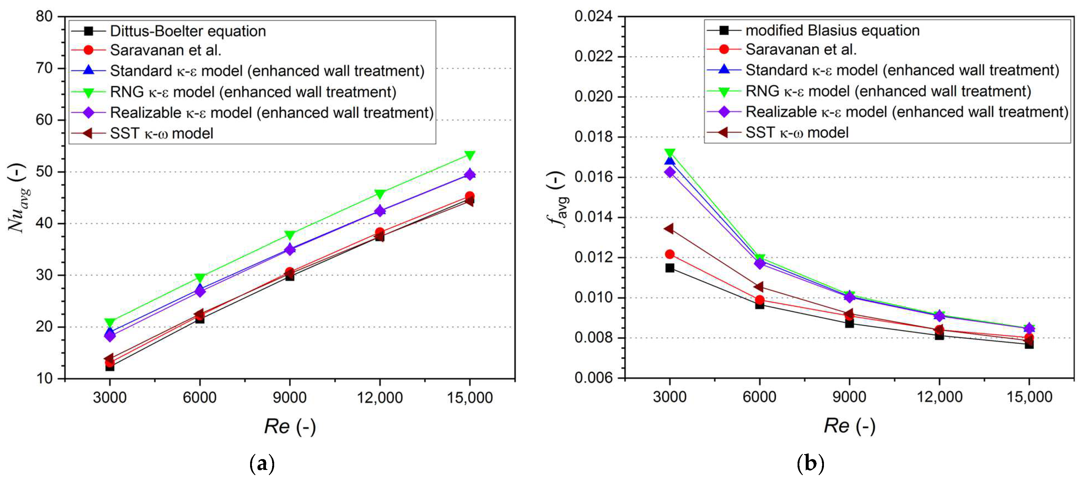
2.4. Validation and Selection of Turbulence Model

To select the most proper turbulence model for the current investigation, the Nusselt number and friction factor were obtained from four different turbulence models for an SAH using a smooth fin due to the lack of experimental data on an SAH combined with fin and turbulator. In the present work, the calculated Nusselt number was compared with the values predicted by the Dittus–Boelter equation, which is widely utilized to validate CFD simulation results [7,11,21], and with the experimental values reported by Saravanan et al. [31] for an SAH with smooth air channel. The Dittus–Boelter equation is given as:
N u s = 0.023 R e 0.8 P r 0.4
To validate the friction factor, this study compared the simulated friction factor with the values obtained from the modified Blasius equation and with the experimental values reported by Saravanan et al. [31]. The modified Blasius equation can be expressed as [39,40]:
f s = 0.085 R e 1 / 4
Figure 4 presents the Nusselt number and friction factor attained from the CFD simulation along with the values predicted by the Dittus–Boelter equation and modified Blasius equation. The comparison results clearly illustrate that both the Nusselt number and friction factor obtained from the SST k - ω model are closest to the results predicted by the empirical equations with a mean absolute percent error (MAPE) of 4.05% for the Nusselt number and 7.53% for friction factor. To compare with Saravanan et al.’s results, the MAPE for Nusselt number and friction factor are 2.50% and 4.03%, respectively. Therefore, the SST k - ω model was considered to be the most suitable among the investigated turbulence models for the current work and was employed for further analysis, similar to other related research [21,38,41,42].

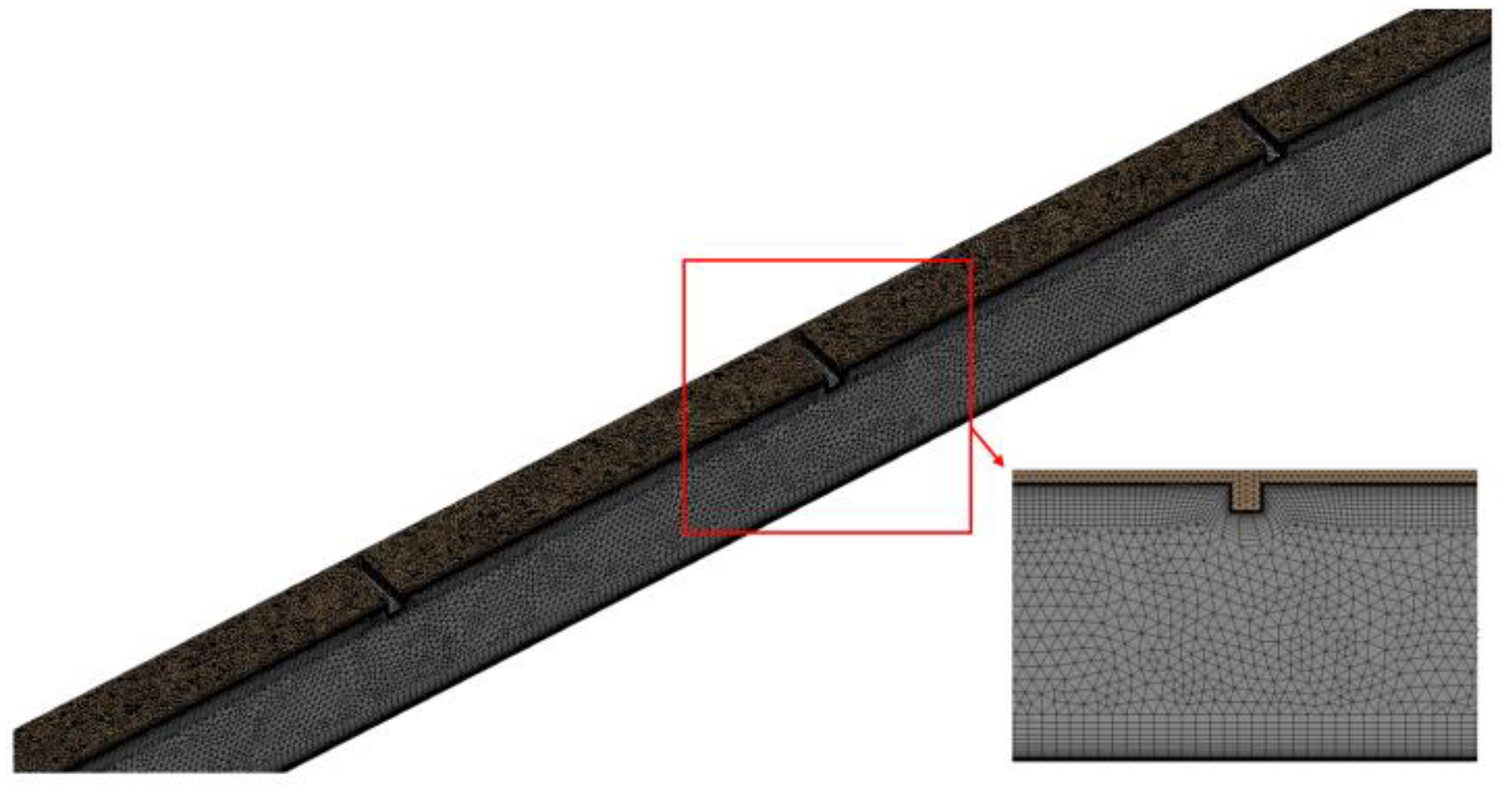
2.5. Grid Independence Test

The grid independence test was performed with various cell numbers. The unstructured mesh was created non-uniformly using the ANSYS ICEM, and the fine inflation layer was generated to resolve the boundary layer close to the wall. The thickness of the first layer is set to be less than 1 of the y + value. The total number of cells in the computational domain increased from 2,177,900 to 9,096,384 by modifying the mesh element size. Table 3 presents the changes in Nusselt number and friction factor for Array B with various cell numbers at a Reynolds number of 9000. After reaching 7,516,107 cells, further growing the cell number leads to the Nusselt number and friction factor values changing by less than 1%. Based on the grid independence test, a cell number of 7,516,107 was selected for Array B. Figure 5 shows the meshed computational domain with the selected cell number. The same mesh size and inflation layer were adapted for further analysis of Array A, Array C, and Array D, and the corresponding cell numbers were 7,640,623, 7,558,068, and 7,453,940, respectively.

3. Performance Indicators

The current research examines the effects of different arrangements of turbulators within a finned air channel of an SAH on heat transfer augmentation and friction factor. The average Nusselt number between the air and fin surface is expressed as follows [23,43]:
N u a v g = h a v g D h k a i r
where h a v g represents the average value of the convection heat transfer coefficient, while D h and k a i r represent the hydraulic diameter and thermal conductivity of the air, respectively. The h a v g was obtained from Equation (9) [23,43].
h a v g = Q ˙ t A f i n , t T f i n , a v g T a i r , a v g
where Q ˙ t represents the total amount of heat transferred from the fin’s surface to the fluid, A f i n , t represents the total area of the installed fin, T f i n , a v g represents the average value of the fin temperature, and T a i r , a v g represents the average value of the air temperature.
The average friction factor was calculated using the following equation [43,44]:
f a v g = P / L D h 2 ρ a i r V a i r 2
The installation of the turbulator boosts heat transfer performance, but it entails a friction penalty because the turbulator increases the obstruction to fluid flow in a finned air channel. Therefore, the thermo-hydraulic performance (THP) that incorporates both the augmentation in heat transfer and friction penalty has been widely used to assess the effectiveness of the proposed heat transfer device in many related studies [4,5,6,10,13,45,46]. This study also evaluated the THP value to determine the best arrangement of the turbulator for the finned air channel of an SAH. The THP is given as:
THP = N u a v g / N u s f a v g / f s 1 / 3
The higher the THP, the greater the thermal augmentation that would be achieved under the same friction penalty.

4. Results and Discussion
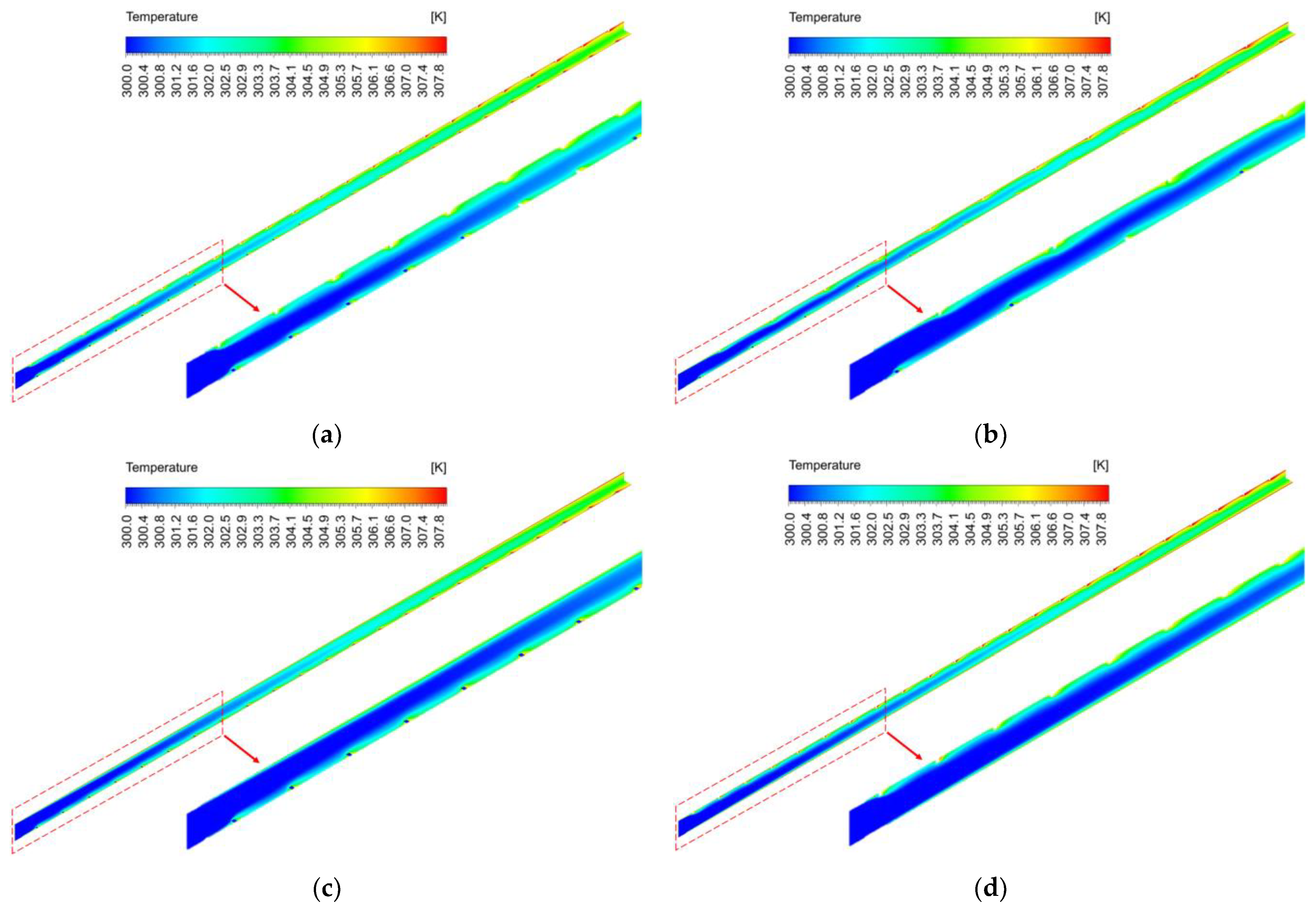
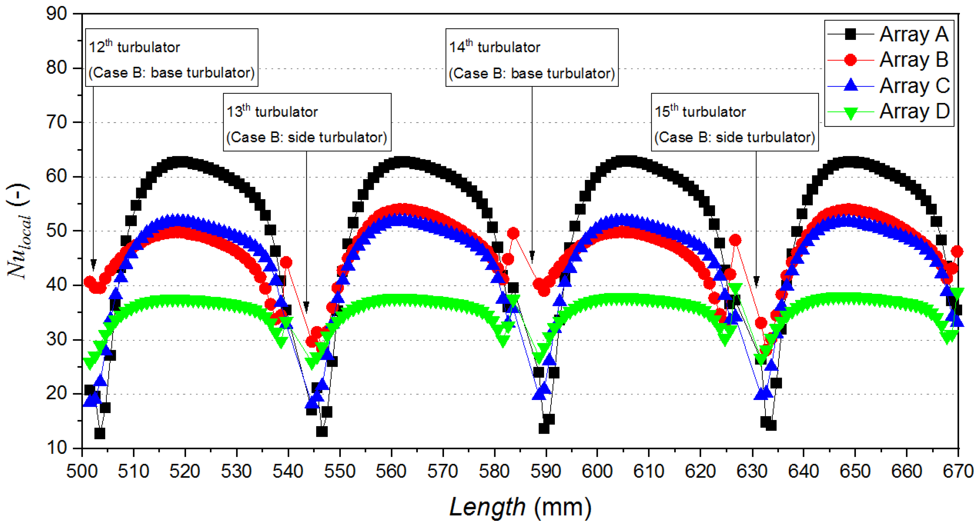
4.1. Heat Transfer

Figure 6 presents the Nusselt number and its augmentation for different arrangements of the rectangular turbulator. The average Nusselt number varied from 20.9 to 74.96, 19.88 to 72.23, 19.31 to 66.31, and 15.79 to 53.18 for Array A, Array B, Array C, and Array D, respectively. For all arrangements, it was seen that the heat could be conveyed more effectively from the fin to the air due to the installation of turbulators. The Nusselt number rises with increasing Reynolds number owing to the increase in turbulence kinetic energy, which results in better mixing of the flowing fluid.
Figure 7 shows the contour of the turbulence kinetic energy for Array D at different Reynolds numbers with the same scale. From the figure, it could be confirmed that the increment in Reynolds number leads to higher turbulence kinetic energy in the fluid flow field. Additionally, the different arrangements result in different Nusselt number augmentation. Among the investigated arrangements, the greatest Nusselt number augmentation is observed in Array A with a value of 2.16, followed by Array B, Array C, and Array D with values of 2.01, 1.97, and 1.58, respectively. The Array A has a higher average Nusselt number and Nusselt number augmentation for all Reynolds numbers in comparison to other arrangements. This is because the improvement in turbulence kinetic energy in Array A occurs simultaneously on both the side and base surfaces, leading to higher heat transfer. In contrast, the other arrangements enhance the turbulence kinetic energy either on the base surface or the side surface at the same location.
Figure 8 presents the turbulence kinetic energy for different arrangements at a Reynolds number of 9000 with the same scale. As previously stated, the turbulence kinetic energy increased on both the side and base surfaces in Array A, and the amount of turbulence kinetic energy was larger than in the other arrangements. Additionally, it could be observed that the turbulence kinetic energy is predominantly intensified on the side surface in Array C and on the base surface in Array D. Therefore, the mixing of fluid occurs effectively only on the side surface in Array C and only on the base surface in Array D. On the other hand, in Array B, the turbulence kinetic energy increases sequentially on the side and base surfaces, which provides a better mixing of the air and a higher Nusselt number than Array C and Array D, as previously shown in Figure 6.
Figure 9 presents air temperature distribution in a fluid field for different arrangements at a Reynolds number of 9000 with the same scale to confirm the effect of increased turbulence kinetic energy on air temperature. As expected, the air temperature substantially increased in the vicinity of the turbulator due to the increased turbulence kinetic energy. In Array A, a significant increase in air temperature was observed on both the side and base surfaces. In Array B, the air temperature increases sequentially on the side and base surfaces. However, there was a significant increase in air temperature only at the side surface for Array C and only at the base surface for Array D. The results indicate that the increase in air temperature has a similar tendency to the increase in turbulence kinetic energy.
Turbulence kinetic energy and air temperature in the fluid field vary due to different arrangements, which affects the local heat transfer performance. Figure 10 shows the local Nusselt number between the 12th and 15th turbulators along the air channel length at a Reynolds number of 9000 to confirm how the different arrangements affect the local heat transfer performance.
For all arrangements, the local Nusselt number increases after passing the turbulator, and after reaching its maximum value it decreases again. This is because a secondary flow occurs at the back of the turbulator due to the separation of the flow, which increases turbulence kinetic energy, as presented in Figure 11. The increased turbulence kinetic energy is beneficial with regard to heat transfer since the fluid particles near the heated fin surface can effectively transport heat to the relatively cold fluid. Therefore, the local Nusselt number increases behind the turbulator. On the other hand, when the fluid flow is reattached, the local Nusselt number declines since the thermal boundary layer develops again.
However, it can be observed that the different arrangements of the rectangular turbulator result in different increments in the local Nusselt number. Array A exhibits the most significant augmentation of the local Nusselt number owing to the largest increment in turbulence kinetic energy. In Array B, the heat transfer augmentation by the base turbulator is lower than in Array C. However, due to the mixing of the air around the base surface and the main flow, the heat transfer augmentation attained by the side turbulator in Array B is higher than Array C. Array D shows the lowest augmentation in the local Nusselt number among the investigated arrangements because the turbulence kinetic energy is lower than other arrangements. Consequently, Array A has the highest average Nusselt number over the total length, followed by Array B, Array C, and Array D, as confirmed in Figure 6. It is also notable that Array B has better heat transfer performance than Array C, despite having a lower number of turbulators.

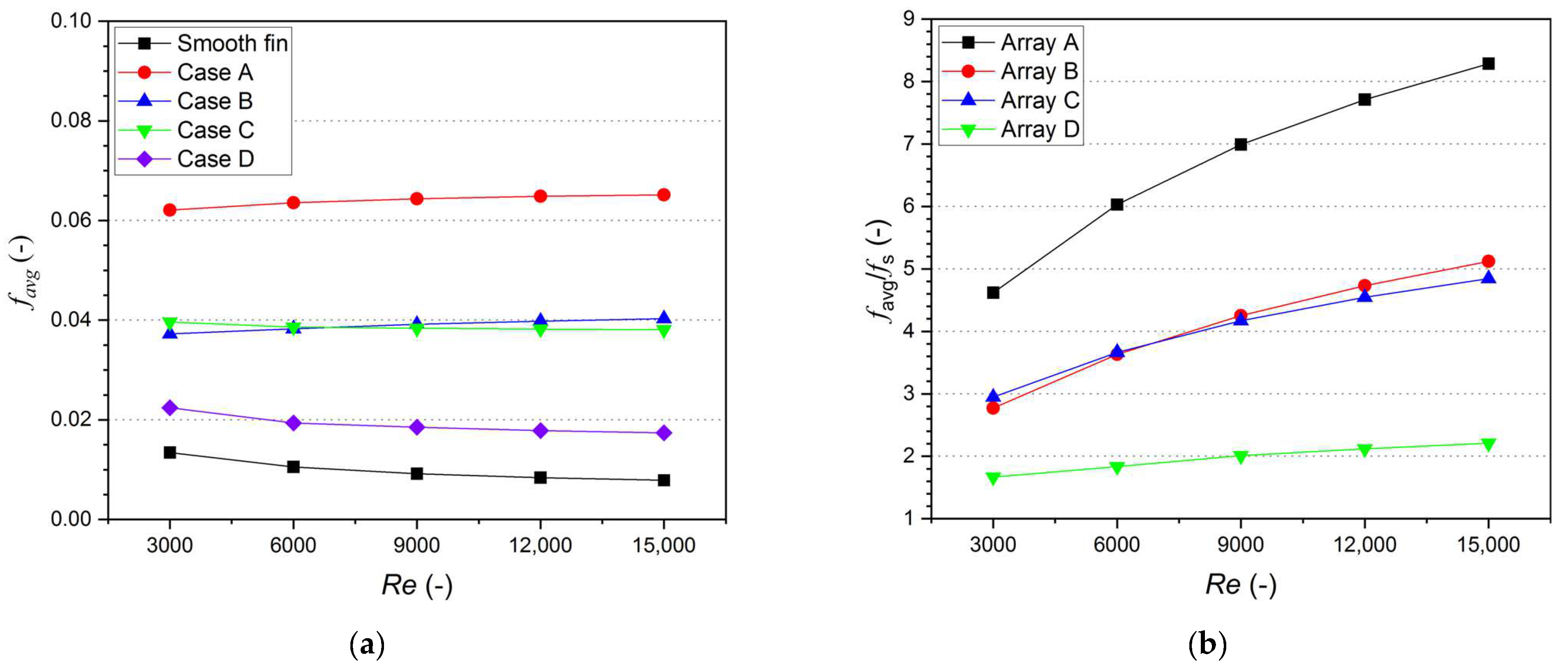
4.2. Friction Factor

The presence of the turbulator improves heat transfer performance, but it has the disadvantage of increasing pressure drop. Figure 12 shows the average friction factor and friction factor enhancement for various arrangements. The average friction factor varied from 0.0621 to 0.0652 for Array A, while these values are in the range of 0.0372 to 0.0403, 0.0381 to 0.0396, and 0.0174 to 0.0224 for Array B, Array C, and Array D, respectively. The results indicate that the presence of the turbulator increases the friction penalty in a finned air channel because it increases the obstruction to airflow, and the different arrangements cause different friction factors. The friction factor enhancement, which represents the ratio of friction factor in a finned air channel coupled with a turbulator to the friction factor in a smooth-finned air channel, is in the range of 4.62 to 8.29 for Array A, 2.77 to 5.12 for Array B, 2.95 to 4.84 for Array C, and 1.67 to 2.21 for Array D. The value of friction factor enhancement increased with an increment in Reynolds number, and the greatest enhancement is observed at a Reynolds number of 15,000 for all arrangements. The most significant enhancement in friction factor is observed in Array A, with a value of 8.29. Meanwhile, the maximum values of friction factor enhancement for Array B, Array C, and Array D are 5.12, 4.84, and 2.21, respectively. This increase in friction factor is generally caused by the formation of a secondary flow, which has the opposite direction to the main flow.
Figure 13 shows a three-dimensional flow pattern inside the finned air channel for different arrangements with the same velocity scale. The lines represent streamlines, while the color of the lines indicate velocity magnitude. In the figure, it can be seen that the secondary flow occurs after the flowing air passes the turbulator. Among the investigated arrangements, Array A exhibits the largest secondary flow region, and a substantial secondary flow was induced at the rear region of the overlap between the side and base turbulators. In Array B, a secondary flow occurs either on the side surface or the base surface, and in Array C, it occurs only on the side surface. It is also seen that the secondary flow region in Array B and Array C is lower than in Array A due to the absence of overlapped turbulators. In Array D, a secondary flow occurs only at the base surface, resulting in the lowest secondary flow region, which results in the lowest enhancement in friction factor.
The most effective arrangement of the rectangular turbulator is one that maximizes heat transfer augmentation while minimizing pressure drop increase. However, the results indicated that the higher heat transfer augmentation was accompanied by a higher friction factor enhancement. This is because the increase in the secondary flow region not only enhances turbulence kinetic energy and mixing of fluid, but also increases pressure drop. For instance, Array A has the highest Nusselt number augmentation but also exhibits the highest enhancement in friction factor. Thus, the most effective arrangement cannot be determined based solely on either Nusselt number augmentation or friction factor enhancement. Therefore, it is necessary to evaluate THP, which incorporates both the thermal augmentation and friction factor.

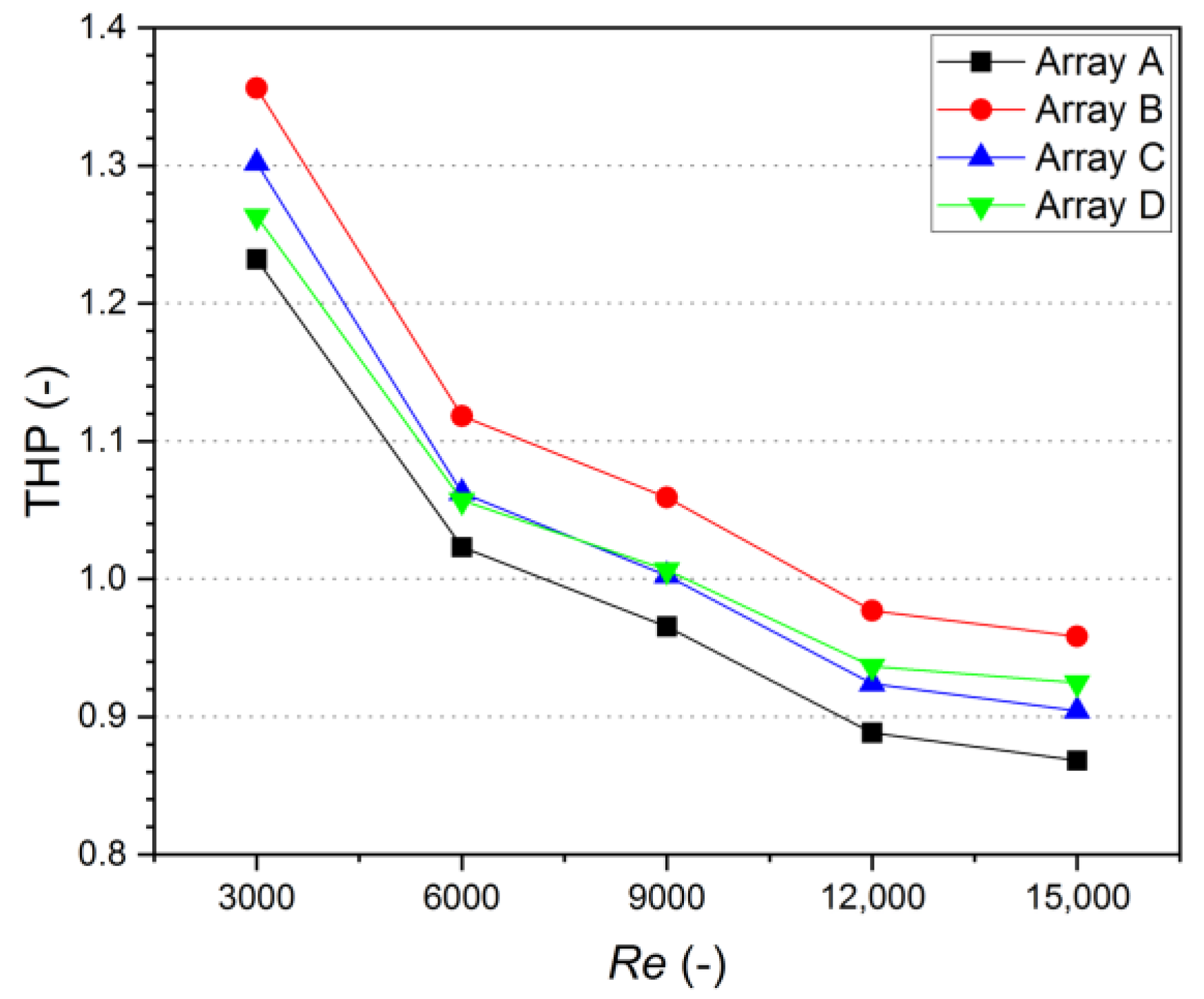
4.3. Thermo-Hydraulic Performance

Figure 14 shows the THP obtained from Equation (6) for different arrangements of the turbulator. The THP varied from 0.87 to 1.23 for Array A, 0.96 to 1.36 for Array B, 0.90 to 1.30 for Array C, and 0.92 to 1.26 for Array D. The value of THP declines with increasing Reynolds number because the increase in the Reynolds number reduces the Nusselt number augmentation and raises the friction factor enhancement. For all arrangements, the maximum THP was observed at a Reynolds number of 3000. Among the investigated arrangements, Array B has the highest THP value of 1.36, while Array A, Array C, and Array D have maximum THP values of 1.23, 1.30, and 1.26, respectively. In addition, Array B has higher THP values for all Reynolds numbers in comparison to the other arrangements. Therefore, Array B, which utilizes side and base turbulators sequentially, is considered the most appropriate and effective arrangement method for the finned air channel of an SAH. On the other hand, Array A shows the lowest THP values for all Reynolds numbers. This is because the large secondary flow regions, which are created behind the overlap section, result in a large friction factor. Thus, Array A is regarded as an unsuitable arrangement method among the investigated methods, despite its higher Nusselt number augmentation.

5. Conclusions

In this research, the effects of four different arrangements of rectangular turbulator in a finned air channel of an SAH on the Nusselt number augmentation and friction factor enhancement were discussed in detail. In addition, the THP values were evaluated to find the most effective arrangement for the finned air channel of an SAH. The major conclusions drawn from the current research are as follows:
(i)
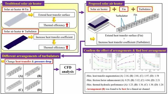
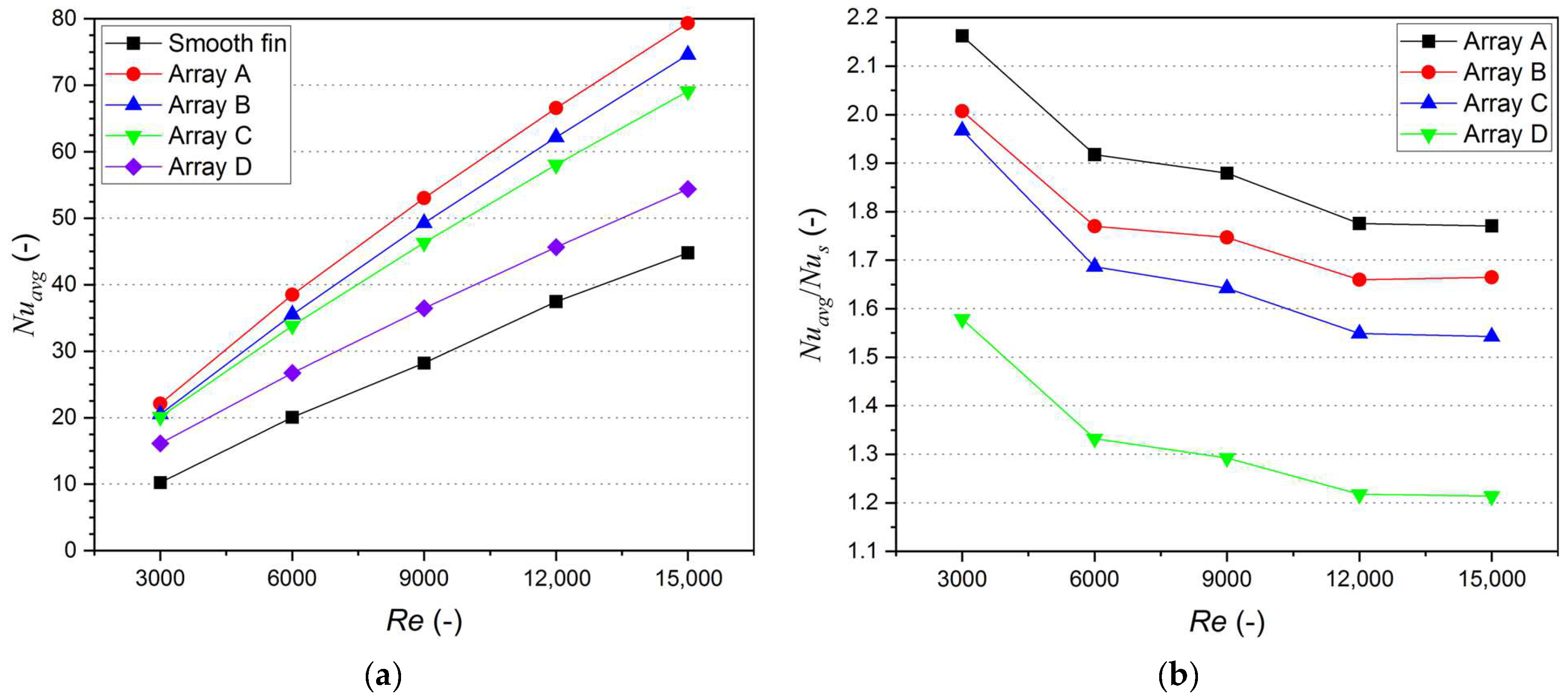
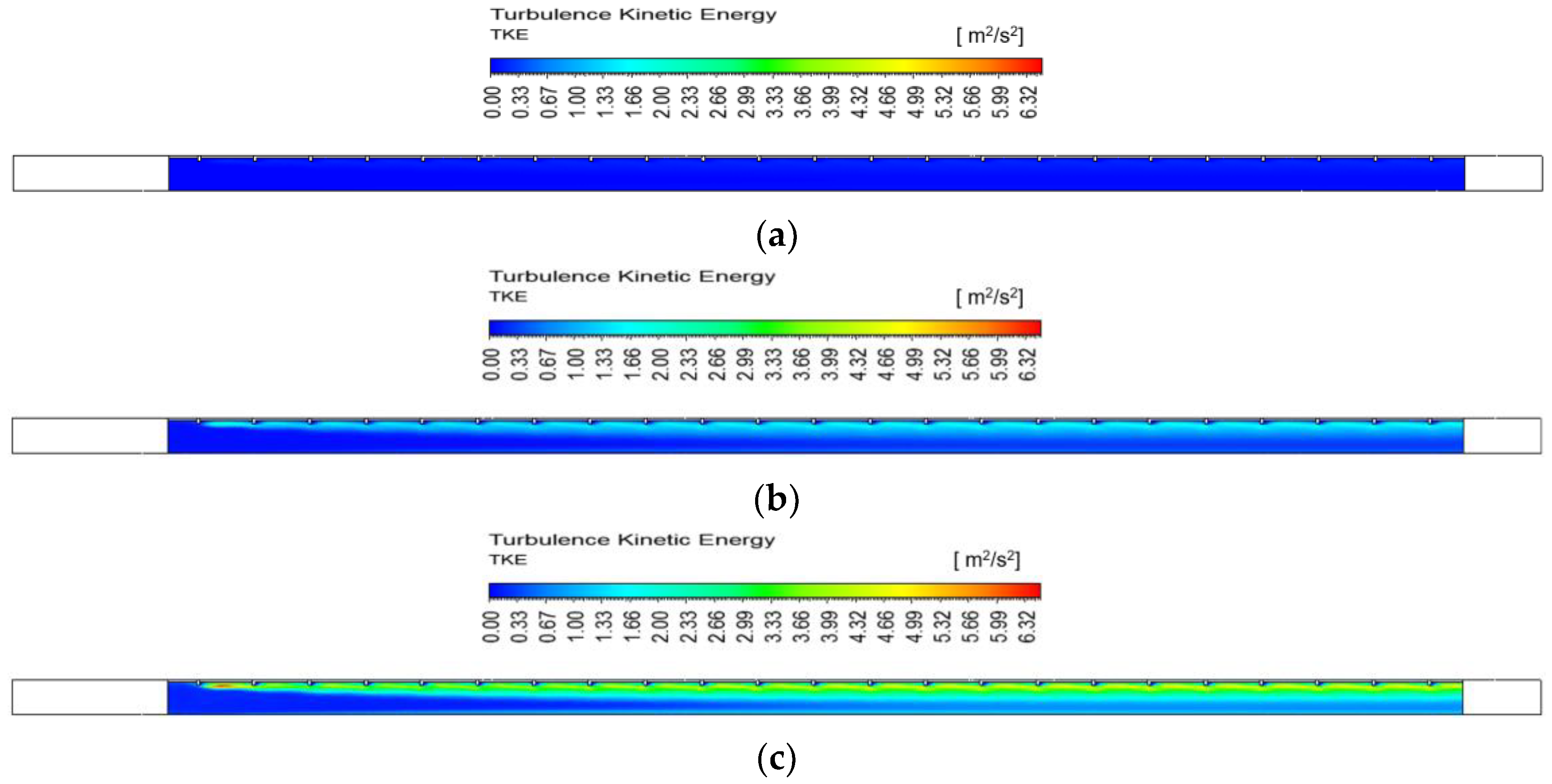
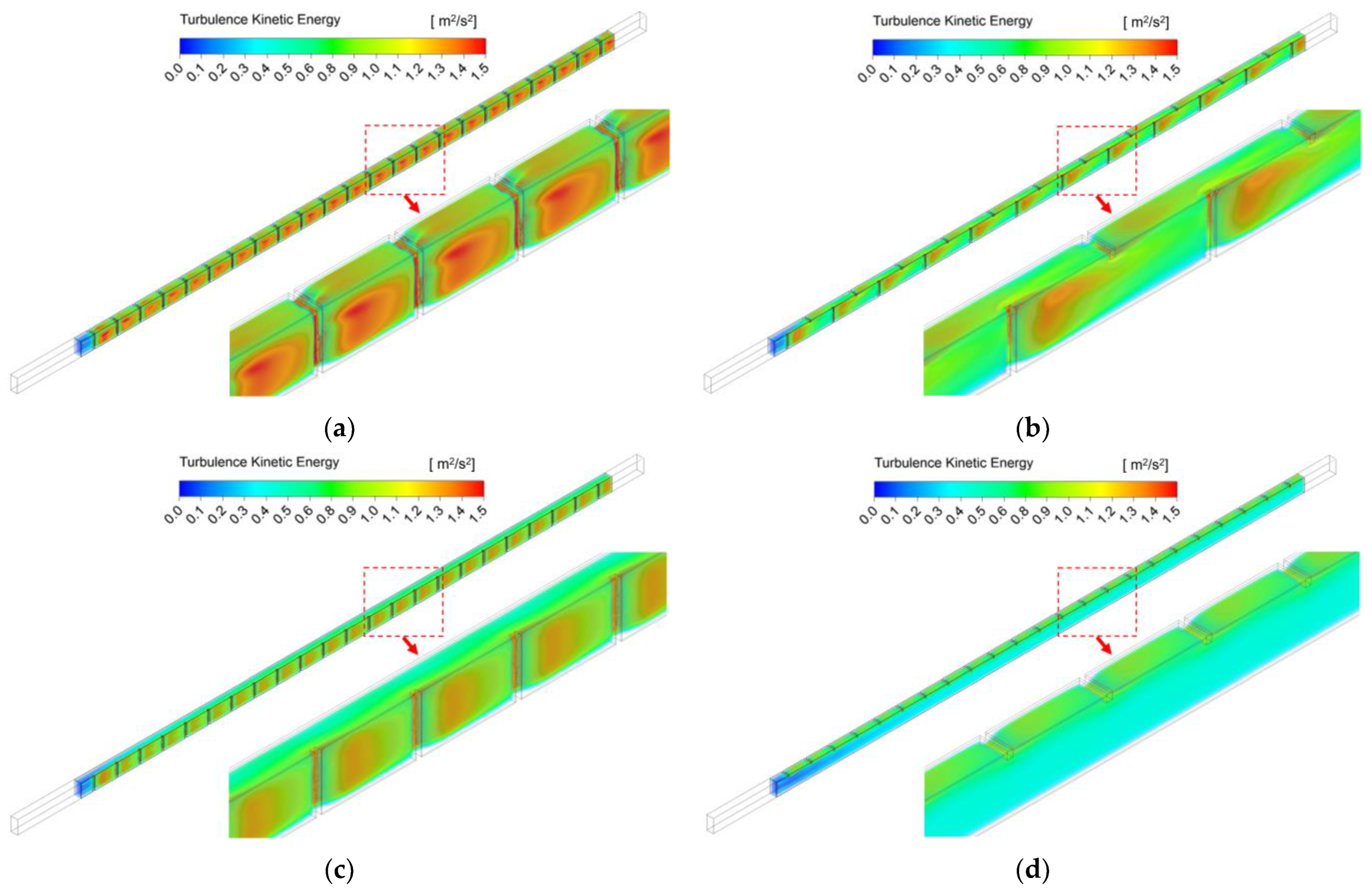
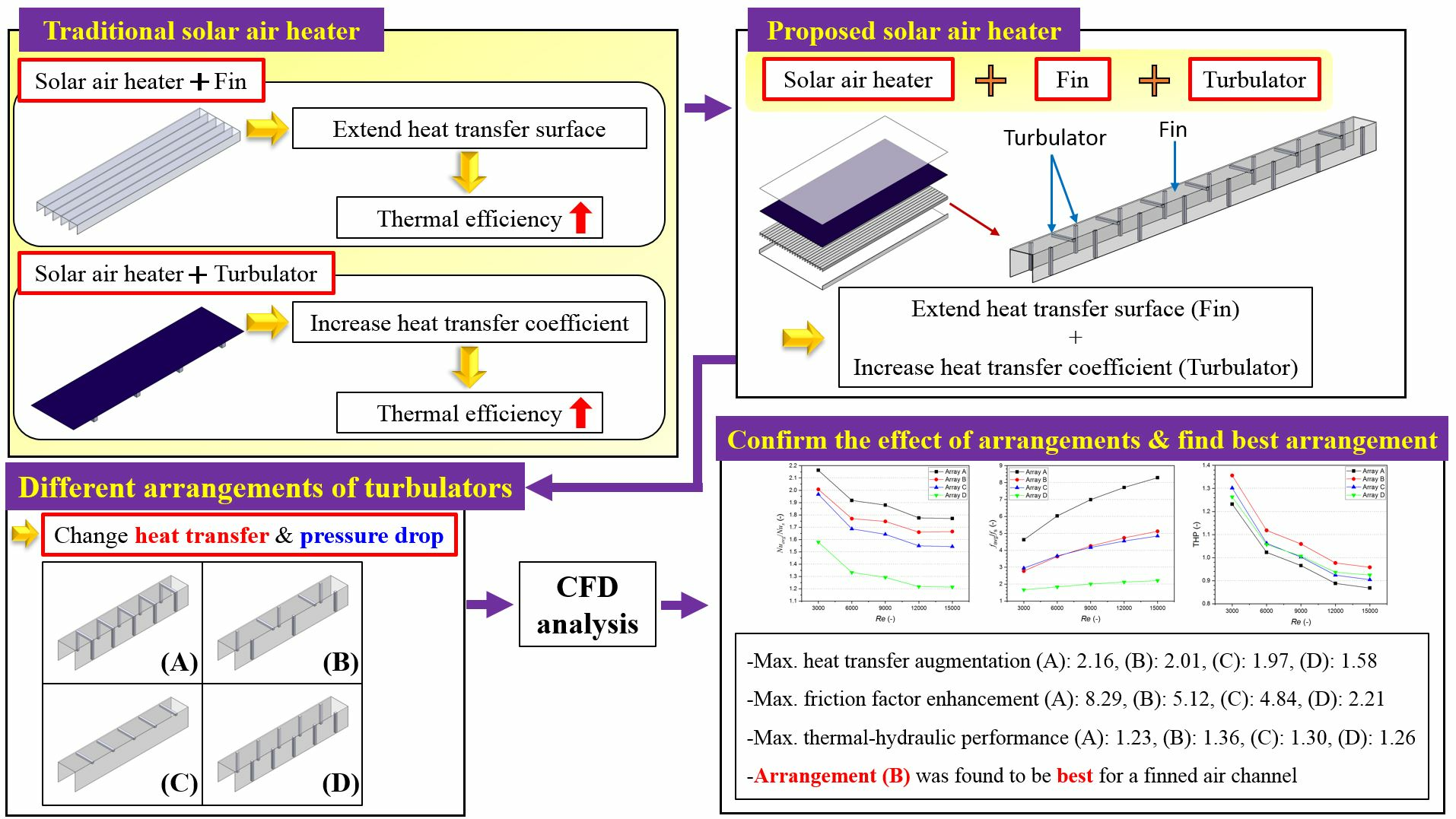
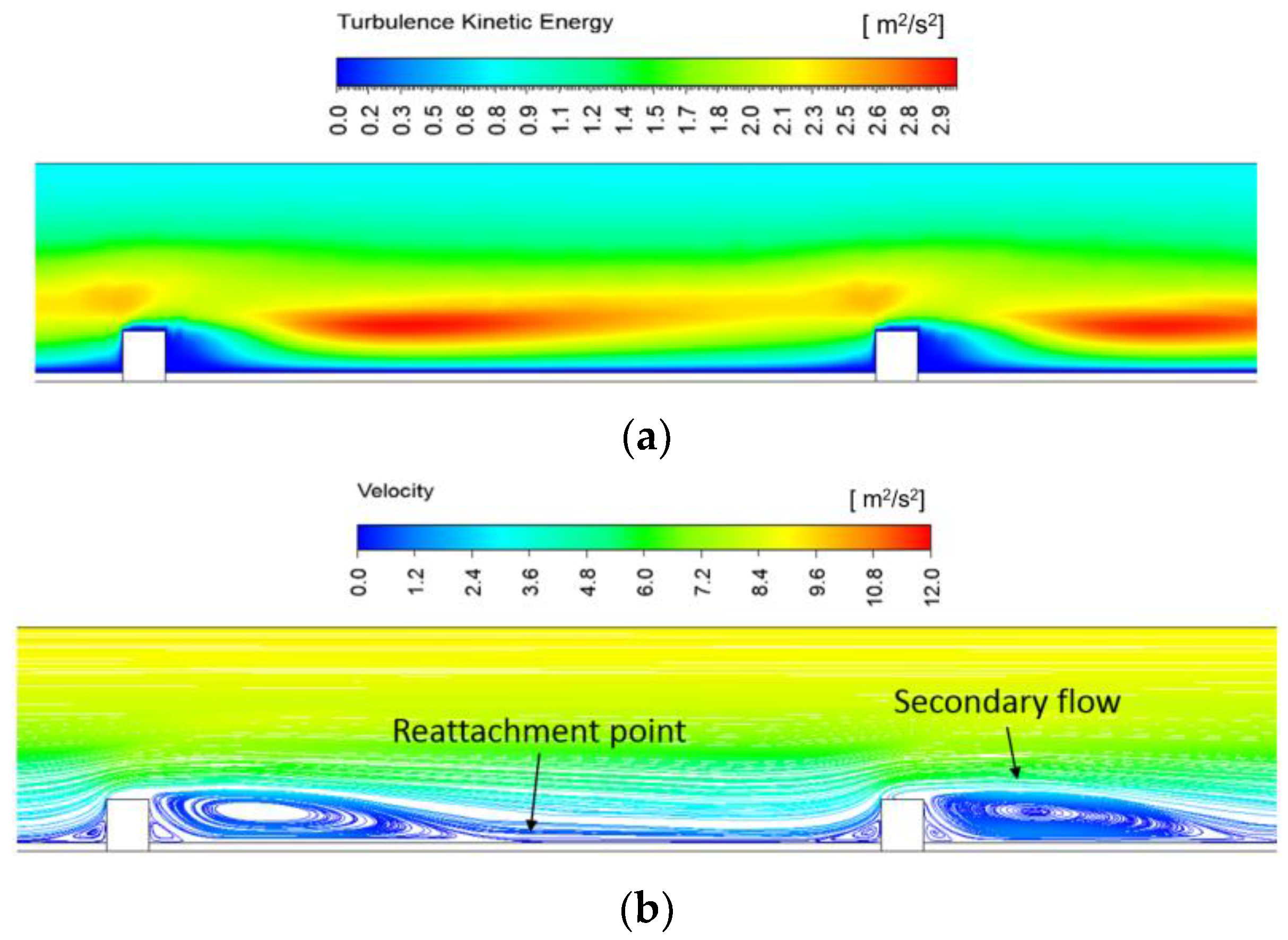
The installation of the turbulator enhanced heat transference from the fin to flowing air. Differing Nusselt number augmentation was observed depending on the arrangement methods of the turbulators due to the different turbulence kinetic energy. Among the investigated arrangements, the highest augmentation in the Nusselt number was observed in Array A with a value of 2.16, while Array B, Array C, and Array D had maximum Nusselt numbers of 2.01, 1.97, and 1.58, respectively.
(ii)
The different arrangements of the turbulator resulted in different friction factors in a finned air channel of an SAH. The most significant enhancement in the friction factor was observed in Array A, with a value of 8.29, followed by Array B, Array C, and Array D, with maximum friction factor enhancements of 5.12, 4.84, and 2.21, respectively.
(iii)
The THP was in the range of 0.87 to 1.23, 0.96 to 1.36, 0.90 to 1.30, and 0.92 to 1.26 for Array A, Array B, Array C, and Array D, respectively. The highest THP was found in Array B with a value of 1.36 and Array B has higher THP than those of other arrangements for all Reynolds numbers.
(iv)
In the investigated arrangements, Array B is considered the most appropriate and effective arrangement for the finned air channel of an SAH due to its highest THP value. On the other hand, Array A is considered unsuitable despite its high Nusselt number augmentation due to the significant increase in friction factor.

Author Contributions

Conceptualization, B.-H.A. and H.-U.C.; methodology, K.-H.C. and H.-U.C.; software, B.-H.A.; validation, B.-H.A. and H.-U.C.; investigation, B.-H.A., K.-H.C., and H.-U.C.; data curation, B.-H.A. and H.-U.C.; writing—original draft preparation, B.-H.A. and H.-U.C.; writing—review and editing, K.-H.C. and H.-U.C.; visualization, B.-H.A. All authors have read and agreed to the published version of the manuscript.

Funding

This research received no external funding.

Data Availability Statement

Data available on request.

Conflicts of Interest

The authors declare no conflict of interest.

Nomenclature

A Area (m2)
D h Hydraulic diameter (m)
k thermal conductivity (W/m·K)
h Convection heat transfer coefficient (W/m2·K)
L Air channel length (m)
P Pressure drop (Pa)
Q ˙ Heat transfer rate (W)
V Velocity (m/s)
N u Nusselt number
P r Prandtl number
R e Reynolds Number
Greek symbols
ρ Density (kg/m3)
Subscripts
a i r Air
a v g average
s smooth
f i n Fin
t Total

References

  1. Chamoli, S.; Lu, R.; Xu, D.; Yu, P. Thermal Performance Improvement of a Solar Air Heater Fitted with Winglet Vortex Generators. Sol. Energy 2018, 159, 966–983. [Google Scholar] [CrossRef]
  2. Markam, B.; Maiti, S. Artificial Enhancer for Small-Scale Solar Air Heater—A Comprehensive Review Aspect Ratio. Clean. Energy Syst. 2023, 4, 100046. [Google Scholar] [CrossRef]
  3. Mahanand, Y.; Senapati, J.R. Implementation of Hybrid Rib-Turbulators on the Thermal Performance of Solar Air Heater Duct: A Collective Review. Sustain. Energy Technol. Assess. 2022, 52, 102345. [Google Scholar] [CrossRef]
  4. Yadav, A.S.; Bhagoria, J.L. A CFD (Computational Fluid Dynamics) Based Heat Transfer and Fluid Flow Analysis of a Solar Air Heater Provided with Transverse Wire Rib Roughness on the Absorber Plate. Energy 2013, 55, 1127–1142. [Google Scholar] [CrossRef]
  5. Yadav, A.S.; Bhagoria, J.L. A Numerical Investigation of Square Sectioned Transverse Rib Roughened Solar Air Heater. Int. J. Therm. Sci. 2014, 79, 111–131. [Google Scholar] [CrossRef]
  6. Yadav, A.S.; Bhagoria, J.L. A CFD Based Thermo-Hydraulic Performance Analysis of an Artificially Roughened Solar Air Heater Having Equilateral Triangular Sectioned Rib Roughness on the Absorber Plate. Int. J. Heat Mass Transf. 2014, 70, 1016–1039. [Google Scholar] [CrossRef]
  7. Gawande, V.B.; Dhoble, A.S.; Zodpe, D.B.; Chamoli, S. Experimental and CFD Investigation of Convection Heat Transfer in Solar Air Heater with Reverse L-Shaped Ribs. Sol. Energy 2016, 131, 275–295. [Google Scholar] [CrossRef]
  8. Kumar, S.; Verma, S.K. Three-Dimensional Simulation and Experimental Validation of Solar Air Heater Having Sinusoidal Rib. Energy Sources Part A Recover. Util. Environ. Eff. 2020, 12, 1–19. [Google Scholar] [CrossRef]
  9. Kumar, R.; Goel, V.; Kumar, A. Investigation of Heat Transfer Augmentation and Friction Factor in Triangular Duct Solar Air Heater Due to Forward Facing Chamfered Rectangular Ribs: A CFD Based Analysis. Renew. Energy 2018, 115, 824–835. [Google Scholar] [CrossRef]
  10. Kumar, R.; Kumar, A.; Goel, V. Performance Improvement and Development of Correlation for Friction Factor and Heat Transfer Using Computational Fluid Dynamics for Ribbed Triangular Duct Solar Air Heater. Renew. Energy 2019, 131, 788–799. [Google Scholar] [CrossRef]
  11. Kumar, R.; Goel, V. Unconventional Solar Air Heater with Triangular Flow-Passage: A CFD Based Comparative Performance Assessment of Different Cross-Sectional Rib-Roughnesses. Renew. Energy 2021, 172, 1267–1278. [Google Scholar] [CrossRef]
  12. Pandey, N.K.; Bajpai, V.K. Varun Experimental Investigation of Heat Transfer Augmentation Using Multiple Arcs with Gap on Absorber Plate of Solar Air Heater. Sol. Energy 2016, 134, 314–326. [Google Scholar] [CrossRef]
  13. Singh, I.; Vardhan, S.; Singh, S.; Singh, A. Experimental and CFD Analysis of Solar Air Heater Duct Roughened with Multiple Broken Transverse Ribs: A Comparative Study. Sol. Energy 2019, 188, 519–532. [Google Scholar] [CrossRef]
  14. Thao, P.B.; Truyen, D.C.; Phu, N.M. Cfd Analysis and Taguchi-Based Optimization of the Thermohydraulic Performance of a Solar Air Heater Duct Baffled on a Back Plate. Appl. Sci. 2021, 11, 4645. [Google Scholar] [CrossRef]
  15. Bhuvad, S.S.; Azad, R.; Lanjewar, A. Thermal Performance Analysis of Apex-up Discrete Arc Ribs Solar Air Heater-an Experimental Study. Renew. Energy 2022, 185, 403–415. [Google Scholar] [CrossRef]
  16. Verma, S.K.; Prasad, B.N. Investigation for the Optimal Thermohydraulic Performance of Artificially Roughened Solar Air Heaters. Renew. Energy 2000, 20, 19–36. [Google Scholar] [CrossRef]
  17. Bhagoria, J.L.; Saini, J.S.; Solanki, S.C. Heat Transfer Coefficient and Friction Factor Correlations for Rectangular Solar Air Heater Duct Having Transverse Wedge Shaped Rib Roughness on the Absorber Plate. Renew. Energy 2002, 25, 341–369. [Google Scholar] [CrossRef]
  18. Thakur, D.S.; Khan, M.K.; Pathak, M. Performance Evaluation of Solar Air Heater with Novel Hyperbolic Rib Geometry. Renew. Energy 2017, 105, 786–797. [Google Scholar] [CrossRef]
  19. Thakur, S.; Thakur, N.S. Impact of Multi-Staggered Rib Parameters of the ‘W’ Shaped Roughness on the Performance of a Solar Air Heater Channel. Energy Sources Part A Recover. Util. Environ. Eff. 2020, 12, 1–20. [Google Scholar] [CrossRef]
  20. Mahanand, Y.; Senapati, J.R. Thermo-Hydraulic Performance Analysis of a Solar Air Heater (SAH) with Quarter-Circular Ribs on the Absorber Plate: A Comparative Study. Int. J. Therm. Sci. 2021, 161, 106747. [Google Scholar] [CrossRef]
  21. Kumar, S.; Verma, S.K. Heat Transfer and Fluid Flow Analysis of Sinusoidal Protrusion Rib in Solar Air Heater. Int. J. Therm. Sci. 2022, 172, 107323. [Google Scholar] [CrossRef]
  22. Singh, V.P.; Jain, S.; Karn, A.; Kumar, A.; Dwivedi, G.; Meena, C.S.; Cozzolino, R. Mathematical Modeling of Efficiency Evaluation of Double-Pass Parallel Flow Solar Air Heater. Sustainability 2022, 14, 535. [Google Scholar] [CrossRef]
  23. Nidhul, K.; Yadav, A.K.; Anish, S.; Arunachala, U.C. Thermo-Hydraulic and Exergetic Performance of a Cost-Effective Solar Air Heater: CFD and Experimental Study. Renew. Energy 2022, 184, 627–641. [Google Scholar] [CrossRef]
  24. Singh, V.P.; Jain, S.; Karn, A.; Kumar, A.; Dwivedi, G.; Meena, C.S.; Dutt, N.; Ghosh, A. Recent Developments and Advancements in Solar Air Heaters: A Detailed Review. Sustainability 2022, 14, 12149. [Google Scholar] [CrossRef]
  25. Fakoor Pakdaman, M.; Lashkari, A.; Basirat Tabrizi, H.; Hosseini, R. Performance Evaluation of a Natural-Convection Solar Air-Heater with a Rectangular-Finned Absorber Plate. Energy Convers. Manag. 2011, 52, 1215–1225. [Google Scholar] [CrossRef]
  26. Fudholi, A.; Sopian, K.; Ruslan, M.H.; Othman, M.Y. Performance and Cost Benefits Analysis of Double-Pass Solar Collector with and without Fins. Energy Convers. Manag. 2013, 76, 8–19. [Google Scholar] [CrossRef]
  27. Priyam, A.; Chand, P. Thermal and Thermohydraulic Performance of Wavy Finned Absorber Solar Air Heater. Sol. Energy 2016, 130, 250–259. [Google Scholar] [CrossRef]
  28. Priyam, A.; Chand, P. Effect of Wavelength and Amplitude on the Performance of Wavy Finned Absorber Solar Air Heater. Renew. Energy 2018, 119, 690–702. [Google Scholar] [CrossRef]
  29. Bhattacharyya, T.; Anandalakshmi, R.; Srinivasan, K. Heat Transfer Analysis on Finned Plate Air Heating Solar Collector for Its Application in Paddy Drying. Energy Procedia 2017, 109, 353–360. [Google Scholar] [CrossRef]
  30. Kabeel, A.E.; Hamed, M.H.; Omara, Z.M.; Kandeal, A.W. Influence of Fin Height on the Performance of a Glazed and Bladed Entrance Single-Pass Solar Air Heater. Sol. Energy 2018, 162, 410–419. [Google Scholar] [CrossRef]
  31. Saravanan, A.; Murugan, M.; Reddy, M.S.; Ranjit, P.S.; Elumalai, P.V.; Kumar, P.; Sree, S.R. Thermo-Hydraulic Performance of a Solar Air Heater with Staggered C-Shape Finned Absorber Plate. Int. J. Therm. Sci. 2021, 168, 107068. [Google Scholar] [CrossRef]
  32. Chand, S.; Chand, P.; Kumar Ghritlahre, H. Thermal Performance Enhancement of Solar Air Heater Using Louvered Fins Collector. Sol. Energy 2022, 239, 10–24. [Google Scholar] [CrossRef]
  33. Karwa, R. Thermo-Hydraulic Performance of Solar Air Heater with Finned Absorber Plate Forming Multiple Rectangular Air Flow Passages in Parallel under Laminar Flow Conditions. Appl. Therm. Eng. 2023, 221, 119673. [Google Scholar] [CrossRef]
  34. Nagaraj, M.; Reddy, M.K.; Honnesara Sheshadri, A.K.; Karanth, K.V. Numerical Analysis of an Aerofoil Fin Integrated Double Pass Solar Air Heater for Thermal Performance Enhancement. Sustainability 2023, 15, 591. [Google Scholar] [CrossRef]
  35. Alam, M.W.; Souayeh, B. Parametric Cfd Thermal Performance Analysis of Full, Medium, Half and Short Length Dimple Solar Air Tube. Sustainability 2021, 13, 6462. [Google Scholar] [CrossRef]
  36. ANSYS. ANSYS Fluent 12.0 User’s Guide; ANSYS Inc.: Canonsburg, PA, USA, 2009. [Google Scholar]
  37. Wongcharee, K.; Changcharoen, W.; Eiamsa-Ard, S. Numerical Investigation of Flow Friction and Heat Transfer in a Channel with Various Shaped Ribs Mounted on Two Opposite Ribbed Walls. Int. J. Chem. React. Eng. 2011, 9, 2560. [Google Scholar] [CrossRef]
  38. Alam, T.; Kim, M.H. Heat Transfer Enhancement in Solar Air Heater Duct with Conical Protrusion Roughness Ribs. Appl. Therm. Eng. 2017, 126, 458–469. [Google Scholar] [CrossRef]
  39. Nidhul, K.; Yadav, A.K.; Anish, S.; Arunachala, U.C. Efficient Design of an Artificially Roughened Solar Air Heater with Semi-Cylindrical Side Walls: CFD and Exergy Analysis. Sol. Energy 2020, 207, 289–304. [Google Scholar] [CrossRef]
  40. Patel, S.S.; Lanjewar, A. Experimental Investigation of Solar Air Heater Duct with Discrete V-Rib Integrated with Staggered Elements. Int. J. Sustain. Eng. 2021, 14, 162–171. [Google Scholar] [CrossRef]
  41. Chaube, A.; Sahoo, P.K.; Solanki, S.C. Analysis of Heat Transfer Augmentation and Flow Characteristics Due to Rib Roughness over Absorber Plate of a Solar Air Heater. Renew. Energy 2006, 31, 317–331. [Google Scholar] [CrossRef]
  42. Boulemtafes-Boukadoum, A.; Benzaoui, A. CFD Based Analysis of Heat Transfer Enhancement in Solar Air Heater Provided with Transverse Rectangular Ribs. Energy Procedia 2014, 50, 761–772. [Google Scholar] [CrossRef]
  43. Choi, H.U.; Moon, K.A.; Kim, S.B.; Choi, K.H. CFD Analysis of the Heat Transfer and Fluid Flow Characteristics Using the Rectangular Rib Attached to the Fin Surface in a Solar Air Heater. Sustainability 2023, 15, 5382. [Google Scholar] [CrossRef]
  44. Choi, H.U.; Choi, K.H. CFD Analysis on the Heat Transfer and Fluid Flow of Solar Air Heater Having Transverse Triangular Block at the Bottom of Air Duct. Energies 2020, 13, 1099. [Google Scholar] [CrossRef]
  45. Singh, I.; Singh, S. CFD Analysis of Solar Air Heater Duct Having Square Wave Profiled Transverse Ribs as Roughness Elements. Sol. Energy 2018, 162, 442–453. [Google Scholar] [CrossRef]
  46. Gupta, A.D.; Varshney, L. Performance Prediction for Solar Air Heater Having Rectangular Sectioned Tapered Rib Roughness Using CFD. Therm. Sci. Eng. Prog. 2017, 4, 122–132. [Google Scholar] [CrossRef]
Figure 1. Schematic of solar air heater incorporating fin and rectangular turbulator.
Energies 16 06891 g001
Figure 2. Schematic of the computational domain (a) 3D model; (b) schematic of the side view.
Energies 16 06891 g002
Figure 3. Arrangements of the rectangular turbulator investigated in the current research: (a) Array A; (b) Array B; (c) Array C; (d) Array D.
Energies 16 06891 g003aEnergies 16 06891 g003b
Figure 4. Simulation results obtained from different turbulence models versus empirical equations: (a) Nusselt number; (b) friction factor [31].
Energies 16 06891 g004
Figure 5. Meshed domain with the selected cell number.
Energies 16 06891 g005
Figure 6. Influence of different arrangements on Nusselt number: (a) Average Nusselt number; (b) Nusselt number augmentation.
Energies 16 06891 g006
Figure 7. Contours of turbulence kinetic energy for Array D at different Reynolds numbers: (a) Reynolds number = 3000; (b) Reynolds number = 9000; (c) Reynolds number = 15,000.
Energies 16 06891 g007
Figure 8. Turbulence kinematic energy for different arrangements at Reynolds number of 9000: (a) Array A; (b) Array B; (c) Array C; (d) Array D.
Energies 16 06891 g008
Figure 9. Air temperature distribution in a fluid field for different arrangements at a Reynolds number of 9000: (a) Array A; (b) Array B; (c) Array C; (d) Array D.
Energies 16 06891 g009
Figure 10. Influence of different arrangements on local Nusselt number along the air channel length at a Reynolds number of 9000.
Energies 16 06891 g010
Figure 11. Turbulence kinetic energy and velocity on mid-plane normal to side surface at a Reynolds number of 9000 for Array C: (a) contour of turbulence kinetic energy; (b) streamlines for velocity.
Energies 16 06891 g011
Figure 12. Influence of different arrangements on friction factor: (a) Average friction factor; (b) Friction factor enhancement.
Energies 16 06891 g012
Figure 13. Flow pattern inside the finned air channel at a Reynolds number of 9000: (a) Array A; (b) Array B; (c) Array C; (d) Array D.
Energies 16 06891 g013aEnergies 16 06891 g013b
Figure 14. Influence of different arrangements on THP value.
Energies 16 06891 g014
Table 1. Geometrical parameters used in the simulation.
ParameterValue
Entrance region length (mm), l e n t 120
Test region length (mm), l t e s t 1000
Exit region length (mm), l e x 60
Air channel height (mm), h a c 24
Air channel width (mm), w a c 12
Fin height (mm), h f i n 25
Fin width (mm), w f i n 12.5
Fin length (mm), l f i n 1000
Fin thickness at the base surface (mm), δ f i n ,   b 1
Fin thickness at the side surface (mm), δ f i n ,   s 0.5
Turbulator height at the side surface (mm), h t , s 24
Turbulator width at the side surface (mm), w t , s 2.4
Turbulator length at the side surface (mm), l t , s 2.4
Turbulator height at the base surface (mm), h t , b 2.4
Turbulator width at the base surface (mm), w t , b 12
Turbulator length at the base surface (mm), l t , b 2.4
Turbulator pitch (mm), p 43.2
Table 2. Boundary conditions employed in the current research.
BoundaryConditionsValues
Air inletVelocity (m/s)1.83, 3.65, 5.48, 7.30, 9.13
Reynolds number (-)3000, 6000, 9000, 12,000, 15,000
Air outletConstant pressure (Pa)101,325
At the top of fin’s base surfaceUniform heat flux (W/m2)800
Fin’s side surfaceSymmetry-
Center of air channelSymmetry-
Other wallsAdiabatic-
Table 3. Changes in Nusselt number and friction factor with increasing cell numbers.
Cell Number N u a v g
(-)
Change   in   N u a v g
(%)
f a v g
(-)
Change   in   f a v g
(%)
4,086,51364.02-0.0810-
5,105,28065.251.930.08383.41
6,354,04365.880.960.08572.30
7,516,10765.65−0.340.0846−1.32
8,329,50065.920.400.08470.15
9,096,38465.780.200.0843−0.47
Disclaimer/Publisher’s Note: The statements, opinions and data contained in all publications are solely those of the individual author(s) and contributor(s) and not of MDPI and/or the editor(s). MDPI and/or the editor(s) disclaim responsibility for any injury to people or property resulting from any ideas, methods, instructions or products referred to in the content.

