1. Introduction
Distributed generations (DGs) have significantly changed many features of power systems, such as reducing network losses, voltage profiles, and serving as back-ups, etc. [
1,
2,
3]. Although DGs can improve some electrical parameters, they may cause several types of problems in power systems [
4]. These problems have direct effects on the conventional protection schemes in active distribution networks (ADNs). Blinding protection areas [
5], sympathetic tripping (the false tripping of feeders) [
6], and failures of the auto-reclosers [
7] are the main challenges that are created by the presence of DG units in distribution networks. Blinding zones cause the relay to operate with a delay or non-tripping [
8,
9]. Protective relays are not able to detect faults in the blinding mode. Indeed, when the short circuit of the feeders is smaller than the pickup current of the protective relays, the protection system is under a blinding area [
10]. In sympathetic tripping, the fault current feeds from more than one direction due to the presence of DGs.
The protective relays of the overcurrent (OC) and earth fault (EF) are the conventional protection devices used in ADNs. Traditional inverse time current protective relays have been used as the main protection schemes for radial distribution systems [
11]. There have been several methods proposed to solve the conventional protection problems due to the presence of DGs. In [
12], the protection blinding challenge in the OC protection with the presence of DGs was investigated. The presented method used mathematical formulations to increase the resiliency of the OC protective relays. Changing the protective relay settings to protect the ADN from blinding zones is the conventional method. Changing the trip time of the OC relays may cause protection coordination loss and may cause damage to the power systems [
12]. In [
13], the authors presented a double-inverse OC relay method for improving the coordination with the optimal settings and considering the DGs’ stability constraints. In [
14], a directional OC protection technique for protecting the distribution network with a DG embedded was proposed. Adaptive, directional OC protection was employed to determine the optimal protection setting. However, the directional OC protection scheme is commonly proposed as a solution for the improvement of protection systems’ selectivity in meshed distribution networks. Reference [
15] presented adaptive OC protective relays for microgrid applications with distributed generation. The superposition theorem for the calculation of the relay pickup current was utilized. In [
16], an adaptive, directional OC relay method was presented based on the positive and negative sequences of the current for microgrid protection. Moreover, the proposed method could estimate the direction of the fault using the phase changes during the fault conditions. Reference [
17] presented an adaptive OC protection method with a dual-setting directional recloser to coordinate the recloser–fuse with the presence of DGs in distribution networks. Reference [
18] utilized a dynamic, adaptive OC relaying scheme to estimate the relay pickup that ensured significantly less communication overhead. The method used the communication link to relay the coordination for low short circuit currents in micro-grid modes.
Although conventional protection systems have many advantages, these systems have many challenges when facing network changes such as the presence of DGs. For these reasons, several adaptive, intelligent protection methods have been suggested to protect the power systems with microgrids and the presence of DGs in recent years [
19,
20,
21,
22,
23,
24,
25]. In [
19], an adaptive protection method based on histogram-based gradient boosting in distribution networks was utilized. It used spectral kurtosis for the feature extraction of faulted transient signals. Reference [
20] presented a deep learning method for fault detection based on unsupervised and supervised learning in distribution systems. In [
21], a protection technique according to a deep neural network with Hilbert–Huang transform in micro-grid systems was developed. It used time–frequency signal processing for the feature extraction for the training of the machine learning method. Reference [
22] proposed machine learning (ML) and signal processing tools for fault detection in ADNs. The ML method was based on feedforward neural networks. In [
23], the authors proposed optimal setting group coordination to address the protection problems with mixed-integer linear programming for ADNs. Reference [
24] proposed a radial feeder protection method based on an artificial neural network (ANN). The proposed method used a centralized, intelligent electronic device (CIED) with the current transformers and circuit breakers of the feeder in a 34-node radial test feeder. They require communication links between protective devices. In [
25], a multiagent deep deterministic policy gradient (MADDPG) protection scheme in distribution networks with the presence of DGs was presented. The proposed method had a better performance than that of conventional protection systems.
In this paper, a group method of data handling (GMDH)-based protection scheme is proposed to protect distribution networks with the presence of DGs and high-impedance faults. The proposed method is based on a non-pilot scheme that does not require any communication signals; it has a high-speed fault detection scheme in active distribution networks. The proposed method can detect the fault at the blinding areas in an ADN. Moreover, the method is not dependent on the DG capacity, and it is robust against HIFs. The main scientific contributions of this research are considered to be as follows:
- (i)
GMDH is used for its capability to create simple model equations between input and target variables without attempting to apply feature selection techniques,
- (ii)
Fault detection in blinding areas and improving the protection system in ADNs,
- (iii)
The proposed method achieves high-speed and accurate fault detection independent of the DG capacities, load variations, disturbances, and impedance faults.
The rest of the paper is organized as follows.
Section 2 and
Section 3 elaborate on the proposed conventional overcurrent protective relays and the GMDH-based fault detection method with a flowchart, respectively.
Section 4 discusses the DIgSILENT simulation performance that compares the conventional OC protective relay with the proposed method. Finally, the conclusion is presented in
Section 5.
2. Conventional OC Protective Relay
Overcurrent and earth fault relays have been used as the main protection and conventional protection devices in real distribution networks. The OC and EF protective relay settings are determined by the pickup current (
Ip), fault current (
If), and time setting multiplier (
TMS). In Equation (1) the operating time of OC and EF relays is shown as follows.
where
α and
n are constants of an inverse-definite minimum time (IDMT) that are given in
Table 1 [
26].
A traditional OC protective relay becomes more challenging with the presence of distributed generation.
Figure 1 depicts the conventional OC relay characteristic curve in the operation and blinding zones. The relay has pickup and instantaneous characteristics, which are denoted by “
IP” and “
Iinst”, respectively. The operation time between the pickup and instantaneous currents is according to the inverse time characteristic, and the operation time is a definite time characteristic after
Iinst. A fault with a current less than the pickup current is shown as the OC relay blinding zone, as illustrated in
Figure 1.
3. GMDH Neural Network
Machine learning (ML) techniques are able to solve many different tasks of complex problems with a high accuracy. Therefore, different ML methods have been widely used in power systems, especially in protection schemes, in order to achieve the fast and accurate detection of faults or fault locations [
27,
28]. The use of ML techniques appears to be a promising option for enhancing the ability for fault detection. Within this context, GMDH networks are scrupulously utilized, as they present a reasonable mathematical model between defined input values and output values. The GMDH method can be basically represented as a feed-forward and multilayer neural network. This method is extensively used to create optimal mathematical relations for the modeling of complex systems due to it requiring minimized prior knowledge [
29]. The GMDH technique provides the possibility of creating a self-organizing network by changing the number of neurons, neuron connections, and layers during the training stage to find the best solution. Hence, the structure of the optimal model can be defined by sorting out possible combinations. In addition, two data sets, including the primary training data set and control data set, are utilized for the training stage. When the error rate measured through the control data set is increased, the training stage is stopped to prevent overfitting [
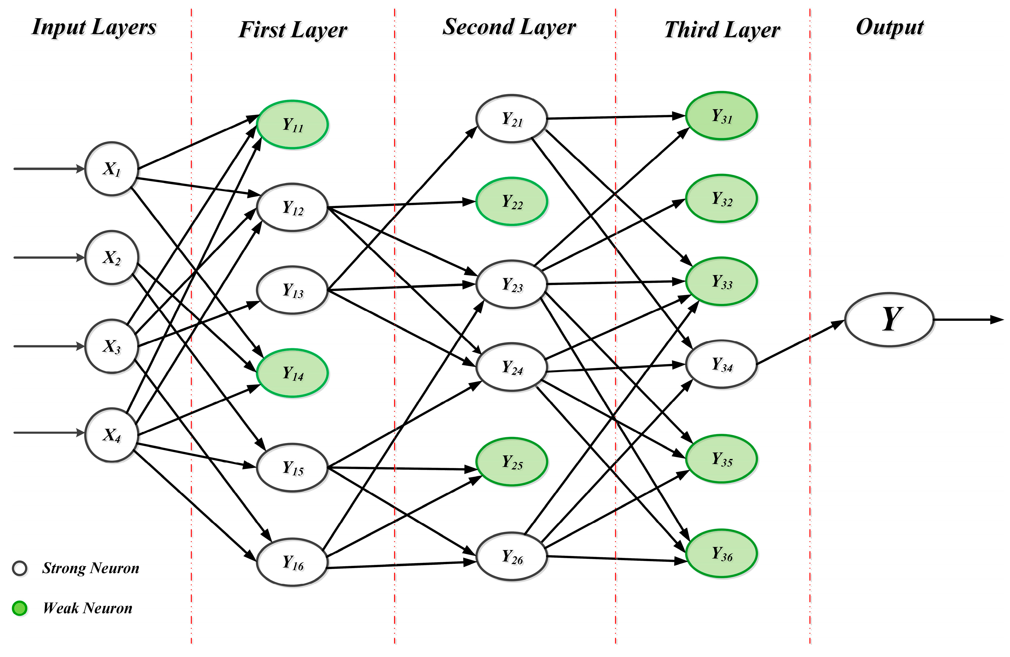
30]. The variables of the training set are cross-recombined to create a pair of variables and are trained as a neuron. The output of the trained neuron can be represented as a high-order polynomial function. These functions in other ways, and the neurons are assessed by defined criteria. The neurons with acceptable performances are preserved for the next layer. Hence, the process is repeated to determine the optimal analytical model among the input and target variables. The general structure of GMDH is illustrated in
Figure 2 [
31].
In
Figure 2, “
x” indicates the input features and “
y” is the output. It can be seen that the output of the previous layer is taken as the input of the next layer. The created input combinations are directly transferred to the first layer. If “
n” is the number of neurons in a layer, the candidate number of neurons for the next layer can be calculated as in Equation (2).
White neurons are strong ones, which are transferred to the next layer. On the other hand, green neurons can be represented as weak ones, which are eliminated after an accuracy assessment. GMDH neural networks generally utilize least squares regression to determine the optimal analytic relation between the input variables and target variables, using a reference function that can be shown in Equation (3) [
31].
where “
” indicates the output value,
represents the input vector, and
shows the polynomial coefficients.
When only the two input parameters are considered, the quadratic form of the equation will be obtained as below.
The coefficients of the polynomial equation are calculated by using the least square method, as given in Equation (5).
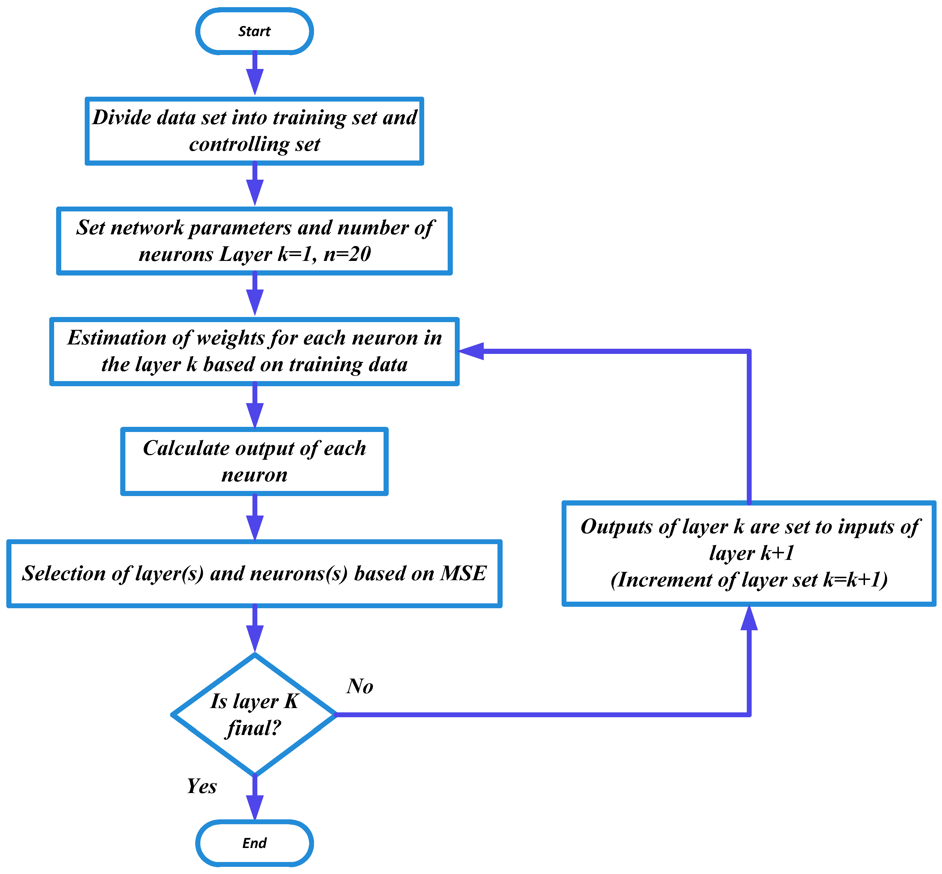
A flowchart that reflects the computational algorithm of the proposed scheme is given in
Figure 3. The data set to be processed is divided into two parts for the training process. The data matrix is created by performing different case studies on the test system. Different fault points and fault impedances are taken into consideration during the data set preparation to increase the sensitivity and selectivity of the fault detection model. The test system matrix G
a×
b with
a = 1200 rows, which show the number of performed cases, and
b = 2 columns, which depict the input features utilized in each case study. The output test matrix F
axb with
a = 1200 rows, which illustrate the target values, and
b = 1, which gives the fault detection. The overall data are divided randomly, in such a manner where 80% of the data are used for the training stage, while 20% of the data are used for preventing overfitting as the control data set. The control data set is employed to stop the training process in order to prevent overfitting. In the training stage, the mean squared error is calculated for each neuron by also applying it to the control data set. The operation behind preventing overfitting stands on measuring the error rate with the control data. When the error rate begins to increase, the algorithm will stop the training. The training process continues to build the next layer if the MSE of the best neuron in the current layer, as assessed using the control data, is less than the MSE of the best neuron in the layer before and the maximum number of layers has not yet been reached. If not, the training process is ended, as shown in
Figure 3.
It should be noted that the training data are obtained through the distribution network given in the DIGSILENT software (version 2022, DIgSILENT, Gomaringen, Germany) by applying faults to several points with different fault impedances. Then, the algorithm is trained by using Matlab software (MATLAB R2022a) and tested through the DIgSILENT Power Factory (version 2022, DIgSILENT, Gomaringen, Germany).on a real active distribution network.
4. Simulation Results
This section is divided into three parts: (1) the case study, (2) the conventional distribution network protection results, and (3) the proposed GMDH-based protection scheme results. The traditional protection device is considered as an OC protective relay in this study.
4.1. Case Study
The case study consists of the real distribution networks of 20 kV feeders with DG.
Figure 4 depicts a single-line diagram (SLD) of the test system. As can be seen from the figure, there are two feeders, a main feeder that the DG is connected to and an adjacent feeder it can ring with. The DG consists of three combined heat and power (CHP) generators, each with a capacity of 2 MW, and it is connected to the distribution network at the PCC. The maximum currents of the main feeder and adjacent feeder are 95 A and 120 A, respectively. The high-voltage substation consists of two 132/20 kV transformers rated at 30 MVA and the three-phase short-circuit current on the substation 20 kV bus is around 14.08 kA.
The candidate fault points in the test system include Point 1 (the middle of the main feeder as the inside zone) and Point 2 (the end of the adjacent feeder, where the feeders are in the ring condition, in which both feeders are fed by the main feeder).
4.2. Overcurrent Protective Relay
In this section, the OC protective relay operations are investigated with different DG capacities and HIFs.
Table 2 illustrates the OC relay settings of the main feeder, PCC, and one of the DGs.
Table 3 introduces the operating times of the main feeder OC protective relay with different DG capacities and HIFs for the fault that occurs at Point 1. The fault current magnitude decreases by increasing the DG capacity and HIF. Therefore, the operating time of the OC relay is increased. The operating times of OC relays linearly increase when increasing the HIF and DG capacity. The feeder relay cannot detect a fault impedance of more than 26 Ω with the presence of DGs. Indeed, the OC protective relay is in the blinding zone. As a result, the operation time of the high-voltage substation feeder protective relay increases with an increase in the DG capacity.
Figure 5 demonstrates a comparison of the OC protective relay characteristic curves of the main feeder, PCC, and DG1 (with a 2 MW capacity) in the case of a 5 Ω impedance fault at Point 1. As can be seen, the substation 20 kV feeders relay operates at 442 ms. On the other hand, the OC protective relay of the PCC and DG1 cannot detect a fault of more than 4 Ω.
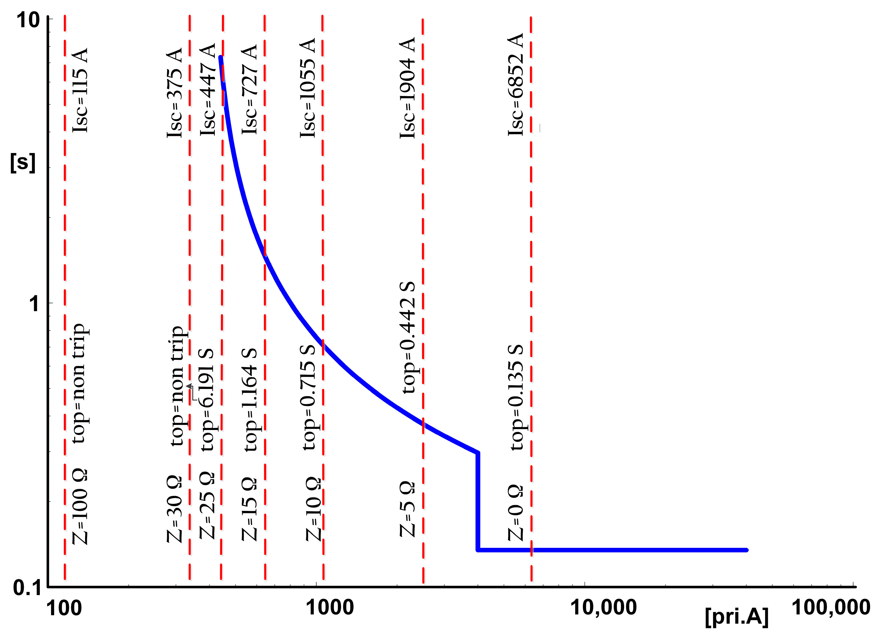
Figure 6 shows the OC protective relay performance of the main feeder with a 6 MW DG capacity for the fault that occurs at Point 1. The performance of the OC relay is shown with different impedance faults. The relay becomes insensitive to detecting faults in the case of fault impedance increments. It can be observed that, for impedance faults more than 26 Ω, the relay fails to detect these faults and remains insensitive by operating in non-trip mode. Therefore, the result reveals the necessity of a robust method for detecting faults with the presence of DGs and HIFs.
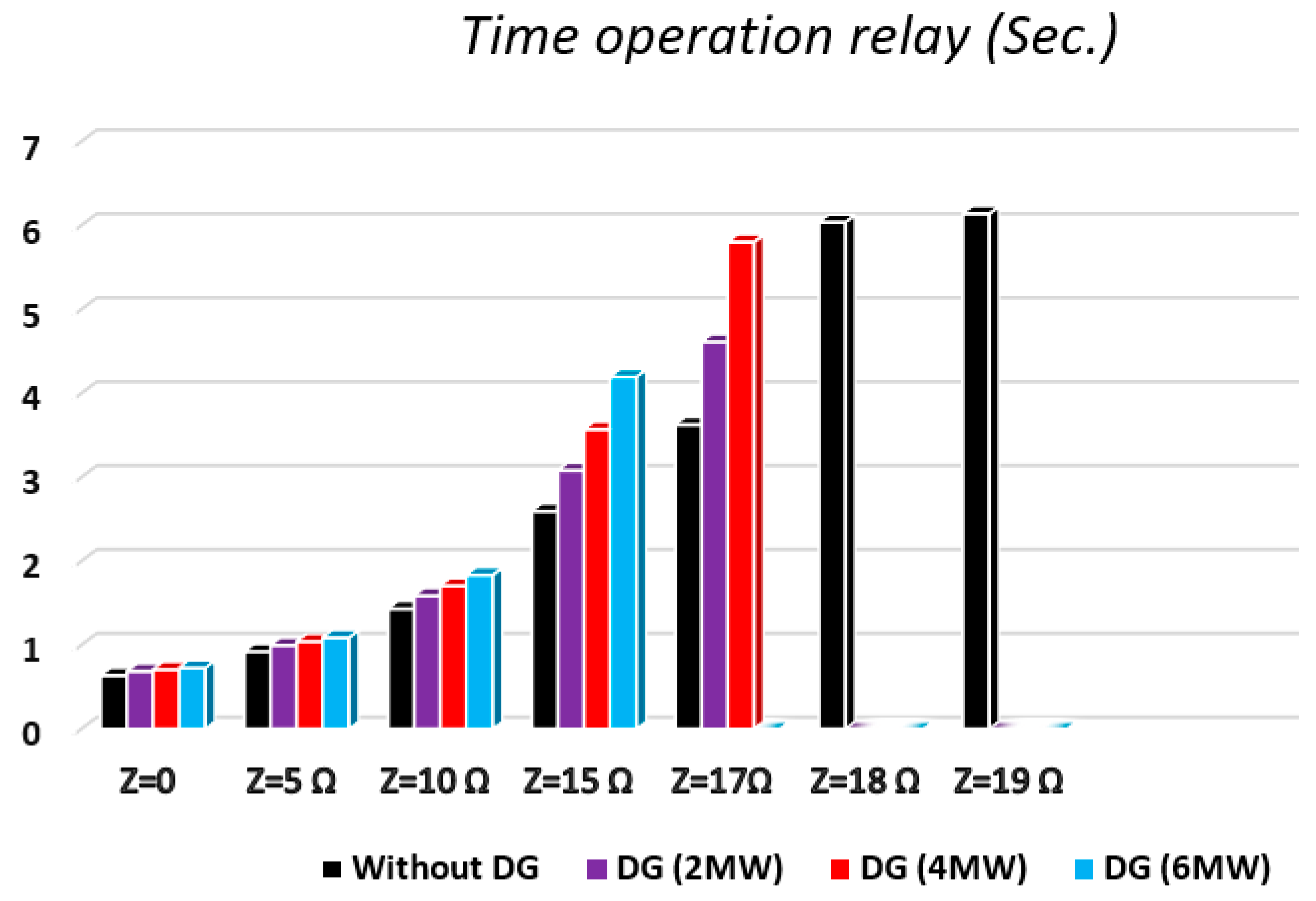
Figure 7 and
Table 4 illustrate the feeder operating times of the OC protective relay with different fault impedances and DG capacities at the ring situation in the case of a fault occurring at Point 2. The relay cannot detect a fault with more than 15 Ω fault resistance and 6 MW DGs.
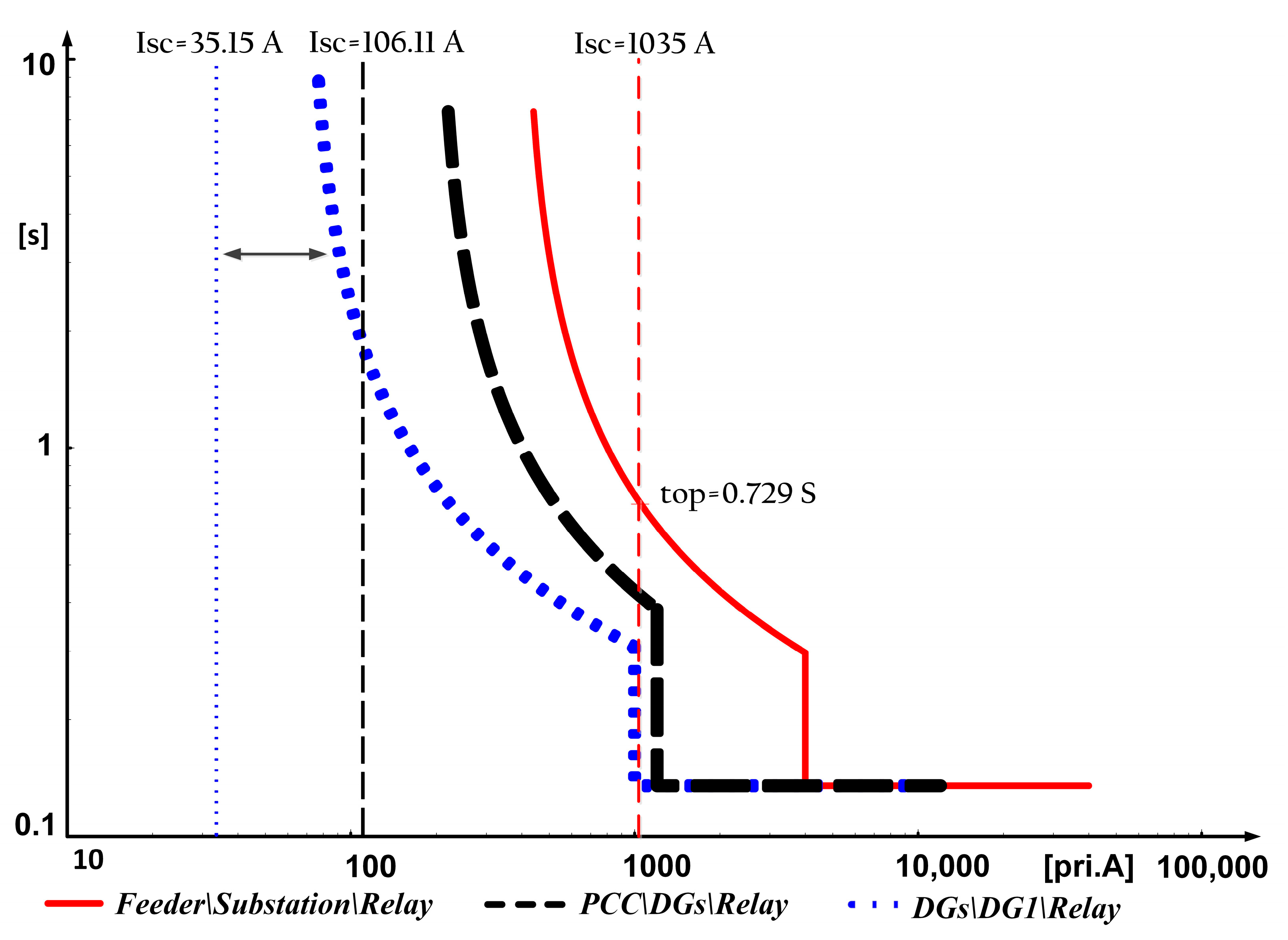
Figure 8 shows the OC protective relay time operation of the main feeder, PCC, and DG1 at the ring situation with a 6 MW DG presence without fault impedance. The OC relay operation of the 20 kV feeder is 729 ms, whereas the DG relays cannot detect faults at the end of the adjacent feeder. Therefore, conventional protection systems cannot effectively protect distribution networks with the presence of DGs and HIFs.
4.3. GMDH-Based Protection Scheme
This section explains the performance of the differential protection scheme based on the ML method, in order to detect faults with the presence of HIFs and DGs in an ADN. Several performance parameters are considered while choosing the ML methods for the fault detection. These parameters are the implementation complexity, computational burden, accuracy, detection speed, and sensitivity to disturbances. During the determination of the method, different machine learning methods, such as linear regression, support vector machines (SVM), decision trees (DT), and random forest (RF), are examined. Many analyses are performed with these ML methods to find the best model in terms of performance parameters. However, linear regression and SVM are eliminated due to their high sensitivity to disturbances. When high fault impedance and noise situations are included in the data set, the accuracy of the model is remarkably reduced. Although the DT and RF methods provide a high accuracy in the case of disturbances in the data set, they fail in terms of the implementation complexity. However, the GMDH network is capable of generating simple model equations. Its easy implementation and high accuracy, independent of the DG capacities, load variations, disturbances, and impedance faults, make this method more attractive.
The created GMDH network is structured by using two variable quadratic models. The parameters for the GMDH network are determined, as given in
Table 5.
The best polynomial model is obtained at the end of the training stage, as given in Equation (6).
N represents the neurons from
N1 to
N16. Each neuron also includes a polynomial equation.
Dg and
F indicate the short-circuit current level of the PCC of the DG and 20 kV feeder of the high-voltage substation, respectively.
The transferred neuron equations are also given in Equation (7).
The obtained transferred neuron equations and best polynomial equation given in Equations (6) and (7) can be summarized, as shown in
Table 6.
To verify the performance of the developed model, some statistical performance indices are utilized. When the accuracy of the developed GMDH-based fault detection method is evaluated according to the mean absolute error (MAE), root mean squared error (RMSE), coefficient of variation (R
2), and mean absolute percentage error (MAPE), the results show that the fault in the power network can be detected in a very short time, thanks to the obtained mathematical model. The overall performance of the developed model is provided in
Table 7.
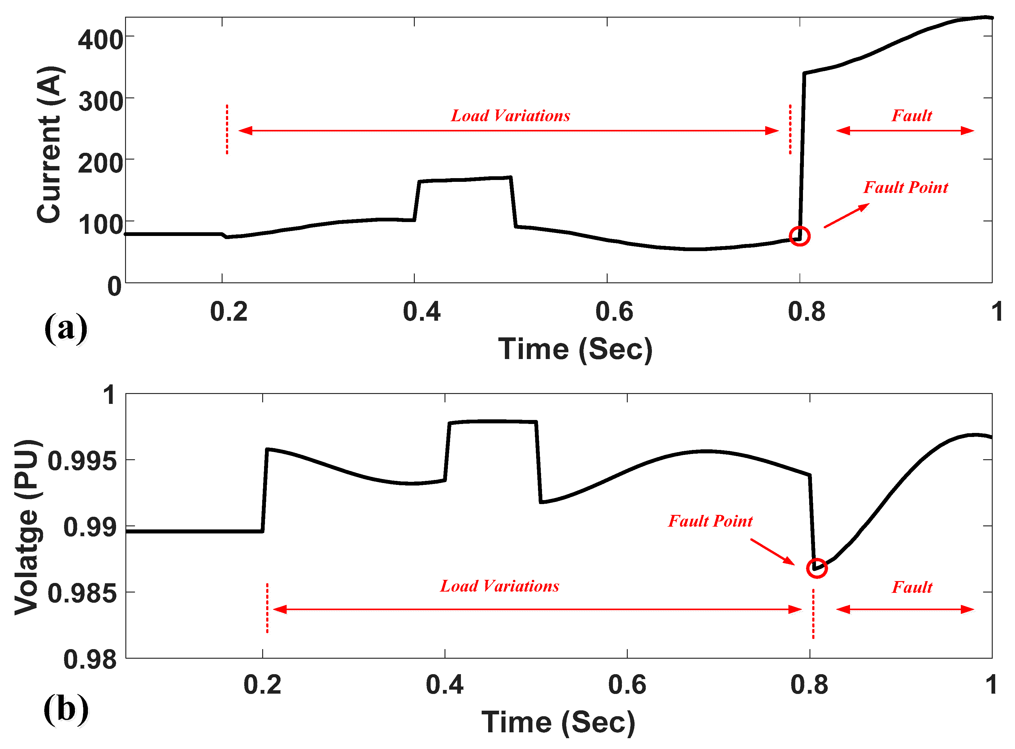
Figure 9 shows the current and voltage of the main feeder during the fault at Point 1 with a 4 MW DG capacity. The short-circuit current is around 1.95 kA with a 5 Ω impedance fault, as shown in
Figure 9a. All the faults are initiated at 0.8 s. The voltage level of the busbar decreases by around 0.07 pu during the fault, as illustrated in
Figure 9b. The different load variations and the change in the operational mode (the ring connection of two feeders) are considered as disturbances in order to reveal the performance of the proposed fault detection method.
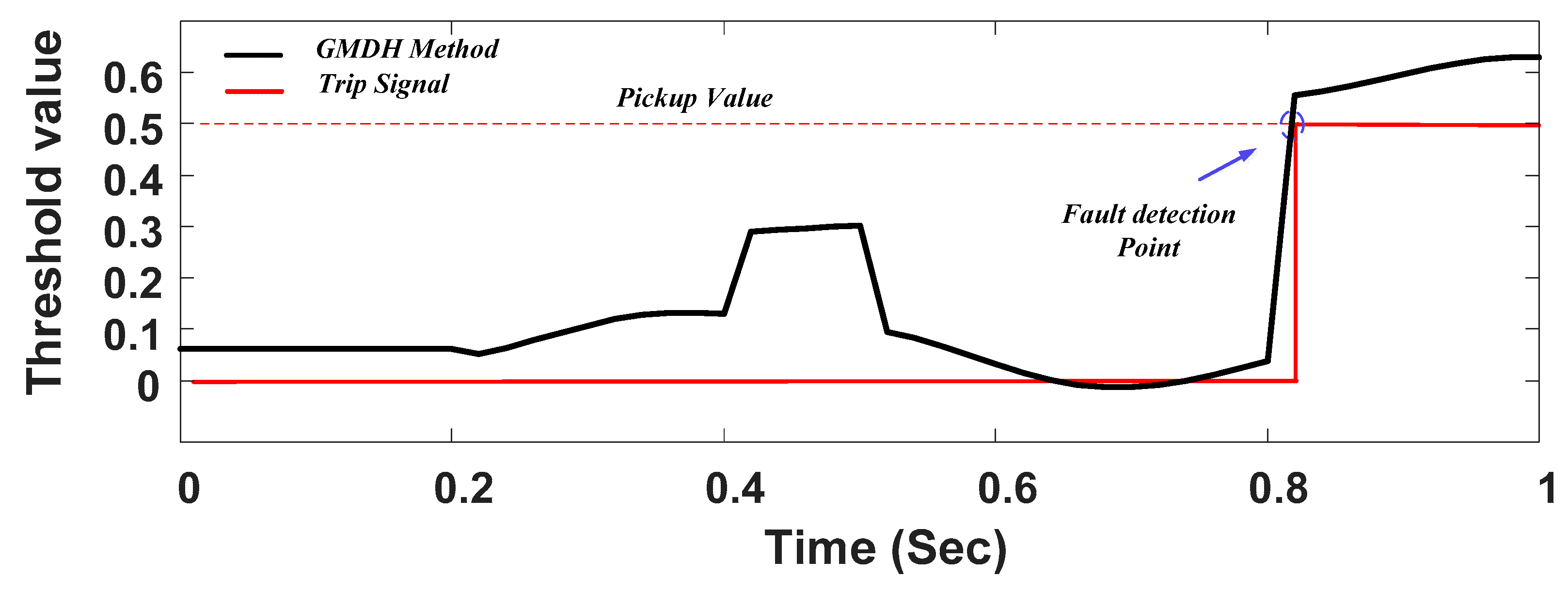
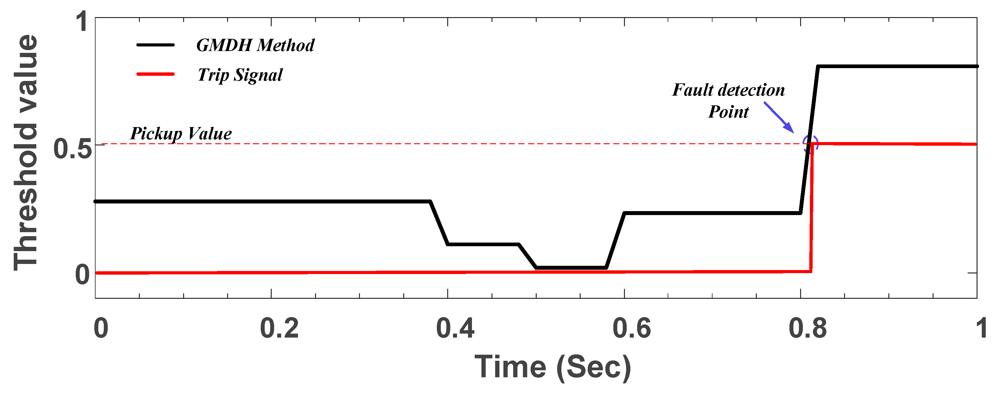
Figure 10 displays the performance of the proposed method during the fault induced at Point 1 with a 4 MW DG capacity and 5 Ω impedance fault. In this case, the threshold value is considered as 0.5 and the fault detection time is obtained around 20 ms. The proposed method has a high-speed operation in comparison to conventional OC relays. The operation time of the conventional OC relay is more than 435 ms with the same short-circuit level, as shown in
Table 3.
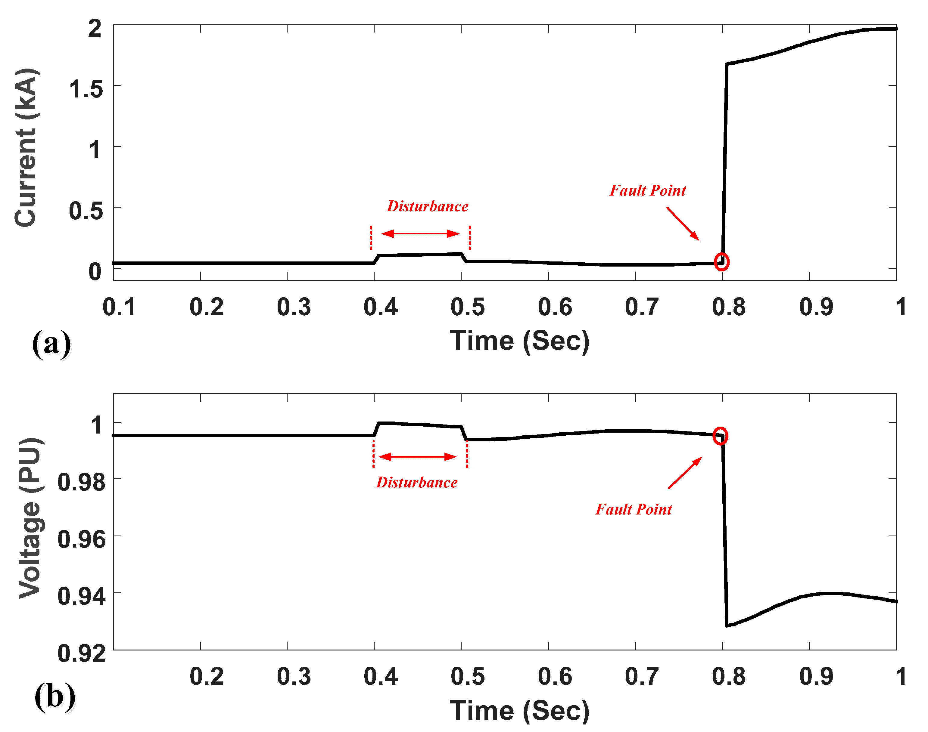
Figure 11 displays the current and voltage of the main feeder during the applied fault at Point 1 with a 6 MW DG capacity. The fault current is around 0.448 kA with a 25 Ω impedance fault, as shown in
Figure 11a. The voltage level of the busbar has some fluctuations during the load variations, as depicted in
Figure 11b. In fault conditions, the voltage level fluctuates. It decreases initially and then it increases due to the high-impedance fault.
Figure 12 shows the performance of the proposed method with the fault at Point 1. The threshold value is considered as 0.5, and the fault detection time is observed around 20 ms with a short-circuit current around 448 A under a 25 Ω impedance fault case. The various load variations with the different DG capacities and the ring connection of two feeders (as disturbances) are considered in order to conduct a performance evaluation of the proposed ML fault detection method. The proposed method has a high-speed operation in comparison to conventional OC relays. The operation time of the conventional OC relay is more than 6 s with the same short-circuit level as that shown in
Figure 6.
Figure 13 displays the performance of the proposed method with a 5 Ω impedance fault and a 6 MW DG capacity under the fault conditions at Point 2. The fault detection time is determined around 20 ms with an 800 A short-circuit current level. The fault is initiated at 0.8 s. The proposed method has a high-speed operation in comparison to conventional OC relays. The operation time of a conventional OC relay is more than 1 s with the same short-circuit level as that given in
Table 4.
Table 8 displays a comparative assessment of the proposed protection method and other existing methods. As can be seen from the table, the proposed protection method shows high-speed fault detection. Moreover, it does not require communication links. The maximum detection time is based on the primary protection.


 ,
, 


