Article

New Renewable Hydrothermal Liquefaction (HTL) Biofuel: A Combustion and Emissions Study in an Optical Engine

by
Shivang Khare
1,*,
Karl Oskar Pires Bjørgen
1,
Komeil Kohansal
2,
Muhammad Salman Haider
2,
Daniele Castello
2,
Thomas Helmer Pedersen
2,
Terese Løvås
1 and
David Robert Emberson
3
1
Department of Energy and Process Engineering, Norwegian University of Science and Technology, 7034 Trondheim, Norway
2
Department of Energy Technology, Aalborg University, 9220 Aalborg, Denmark
3
Department of Marine Technology, Norwegian University of Science and Technology, 7491 Trondheim, Norway
*
Author to whom correspondence should be addressed.
Energies 2023, 16(18), 6754; https://doi.org/10.3390/en16186754
Submission received: 21 August 2023 / Revised: 10 September 2023 / Accepted: 18 September 2023 / Published: 21 September 2023
(This article belongs to the Section J: Thermal Management)

Abstract

:
This study involves the investigation of municipal solid waste (MSW) based biofuel in order to demonstrate its utilization as a diesel blendstock in a compression ignition (CI) engine. The biofuel was produced from the Hydrothermal Liquefaction (HTL) process. The tested biofuels represented both distilled (known as nonupgraded HTL biofuel) and hydrotreated (known as upgraded HTL biofuel) fuels, obtained from raw bio-crude. The effects of the HTL biofuel and diesel blending on the combustion and emission characteristics were investigated. A comparative study of nonupgraded and upgraded HTL biofuel in terms of combustion and emissions was conducted. The upgraded HTL biofuel was blended with reference diesel (RD) by 5%, 10%, and 40% by weight, respectively, and the nonupgraded HTL biofuel was blended with RD by 10% by weight. The experiments were conducted in an optically accessible compression ignition chamber (OACIC) with engine-like thermodynamic conditions. The parameters were recorded at a constant speed and at fixed thermodynamic conditions. The heat release rate (HRR), in-cylinder pressure, ignition delay (ID), flame lift-off length (FLOL), and in-flame soot were measured. The PM, CO, NOx, and CO2 were also recorded. In summary, the HTL blends exhibited a close resemblance to the reference diesel across a range of combustion parameters and regulated emissions. Furthermore, the upgraded HTL blends outperformed the nonupgraded blend in terms of both combustion characteristics and emissions.

1. Introduction

The statement made at the COP26 conference in Glasgow 2021 emphasized the urgent need for the world to achieve net-zero emissions by 2050 in order to combat the detrimental effects of climate change on our planet [1]. The assessment conducted by the Intergovernmental Panel on Climate Change (IPCC) warns of the potentially devastating consequences of future climate change, highlighting the necessity for immediate action. Governments have responded by intensifying their efforts to the transition from fossil fuels to renewables, including advanced biofuels, in alignment with the IPCC’s call for rapid emission reduction and carbon neutrality [2]. One of the primary challenges in meeting these goals lies in finding and employing renewable, sustainable, and ecofriendly alternative fuels, particularly in the road transport sector where automobiles play a significant role. Biofuels, such as biodiesel and ethanol, are regarded as promising substitutes for fossil fuels and have seen widespread commercial application in vehicles [3]. However, their production relies in many cases on edible oils derived from crops, including soybean, rapeseed, palm oils for biodiesel, maize, wheat, and sugarcane for ethanol. The extensive use of these biofuels could potentially impact food security, particularly in developing countries. Additionally, although biofuels are generally viewed as effective in mitigating the release of greenhouse gas (GHG) emissions due to the carbon sequestration process during plant growth, recent studies suggest that considering emissions from land use changes, biofuel production, and consumption might not achieve the desired GHG emission reductions [4,5,6]. Given these concerns, second-generation biofuels, derived from feedstocks, like crop, forestry, and urban waste, offer a more environmentally friendly and sustainable alternative. Additionally, emerging feedstocks, such as microalgae [7], plastics [8], and food waste [9], are garnering attention as they present not only a lower risk to food security but also offer potential advantages in GHG emission reductions. These alternative feedstocks are considered environmentally friendly and can provide a more holistic solution to the complex challenges of sustainable fuel production.
Municipal solid waste (MSW) is among the most abundant feedstock for second-generation biofuels. Over the past few decades, urbanization and population growth in urban areas have led to a significant increase in MSW generation. Eurostat statistics reveal that the average per capita MSW production in the EU stands at approximately 500 kg/year. However, certain member countries surpass this figure, with some reaching levels above 700 kg/year [10]. However, waste treatment facilities have not kept pace with this surge, resulting in a lack of capacity and potential environmental crises. In most countries, organic waste accounts for around 28–58% of the total MSW produced, depending on the region. While this organic waste has traditionally been seen as a troublesome aspect of MSW that hinders recycling technologies, it actually represents a sustainable carbon source that can be utilized for the production of liquid fuels and agricultural nutrients [11]. The organic fraction of MSW contains a significant amount of moisture, making traditional valorization techniques, like incineration, costly. This challenge can be addressed through the employment of the Hydrothermal Liquefaction (HTL) conversion technique. In HTL, the drying of biowaste is unnecessary as the water content serves as a reaction medium to convert lipid and nonlipid components into bio-crude oil [12,13].
Hydrothermal Liquefaction (HTL) is a thermochemical process that utilizes water at sub, near, or supercritical conditions as the reaction medium to break down and decompose the complex organic molecules present in biomass. This process results in the production of an energy-dense liquid known as bio-crude [14]. However, bio-crude obtained from HTL cannot be directly utilized as a drop-in transportation fuel. Despite having a higher quality than pyrolysis oil, it still contains oxygen and other heteroatoms (like nitrogen, sulfur, etc.) that need to be removed. Nitrogen and oxygen compounds can potentially affect the lubrication properties of low-sulfur diesel fuels, which might lead to increased engine wear and reduced performance. Nitrogen compounds in the fuel can increase the production of the oxides of nitrogen (NOx) during combustion, while sulfur leads to the generation of sulfur oxides (SOx). These pollutants (NOx and SOx) have detrimental effects on the environment and human health. Fractional distillation is a commonly employed upgrading process capable of separating the different constituents of bio-crude. Another method of upgrading involves hydrotreating, which removes oxygen and produces a relatively thermally stable oil. The biofuel produced followed by upgrading has a high calorific value in the range of 40–45 MJ/kg and has a lower oxygen content compared to biofuel derived from the pyrolysis process. This makes HTL biofuel favorable for efficient combustion, making it suitable for use as engine fuel [15].
HTL fuels have, however, not reached the level of commercial fuels in maturity and have thus received less attention in the combustion community. Its combustion characteristics are less known compared to more custom biofuels, such as FAME, biodiesel, and methanol. Chen et al. [16] performed engine tests using an upgraded HTL biofuel blended with diesel (HTL 10 and 20% by volume). They measured the exhaust emissions, such as NOx, CO, UHC, and soot. The results showed that the emissions were similar to that of diesel fuel. However, the authors did not investigate the combustion characteristics of HTL biofuel, such as the heat release rate, ignition delay, flame lift-off length, and in-flame soot, which are all important parameters for optimal combustion and efficiency. The work reported by Hossain et al. [17] involved the application of a surrogate of HTL biofuel and diesel blends in an engine. The exhaust emissions were measured; however, there is a contradiction between the soot emissions result of this study and the study by Chen et al. This study also lacks information on the combustion characteristics. The investigation conducted by Hadhoum et al. [18] used nonupgraded HTL and diesel blends (10, 20, and 30% HTL by volume). The authors studied the combustion and emission characteristics, but the combustion features, such as the flame lift-off length and in-flame soot formation, were not investigated. The main difference between the study of Hadhoum et al. (nonupgraded HTL) and of Chen et al. (upgraded HTL) is that the CO and soot emissions are lower in the upgraded HTL relative to the nonupgraded HTL. An experimental study was performed by Nabi et al. [19] in an engine fuelled with nonupgraded HTL and diesel blends (5, 10, and 20% HTL). The authors studied the combustion features, such as the in-cylinder pressure and heat release rate; however, the study did not discuss the flame lift-off length and in-flame soot formation. The exhaust soot emissions results of this study and the study by Hadhoum et al. also show a contradiction. Obeid et al. [20] reported the work related to the utilization of a surrogate of HTL biofuel in an engine; this study also lacks a detailed combustion investigation. Lee et al. [21] conducted tests using upgraded HTL and diesel blends (10 and 20% HTL) in a constant volume chamber. The authors completed a detailed combustion study; however, the investigation of the higher HTL concentration was missing. The detailed combustion study performed by Yang et al. [22] used 100% upgraded HTL biofuel in a constant volume chamber. They measured the heat release rate, in-cylinder pressure, ignition delay, flame lift-off length, and in-flame soot. However, the study lacks a comparative investigation of nonupgraded and upgraded HTL biofuel in terms of combustion and emission characteristics. Overall, there are very few studies conducted on HTL-fuelled engines. The studies lack a detailed combustion investigation of HTL biofuel. The emission results of previous studies by other authors are not consistent, especially soot emissions, so further work is needed in this domain as well. Also, the comparative investigation of the upgraded and nonupgraded HTL biofuel in terms of the combustion and emission features was not performed by the research community as per the authors’ knowledge. These research gaps need to be addressed in order to understand the behavior of this fuel in the engine. A comparative study of upgraded and nonupgraded HTL biofuel is also beneficial in order to understand how fuel upgrading is beneficial (or not) as it involves extra cost in fuel production. Furthermore, these are the necessary precursors for the commercial application of this fuel in conventional diesel engines. Therefore, work on these research gaps is in high demand.
The current work addresses these research gaps; the effects of HTL biofuel and diesel blending on combustion and emission characteristics were investigated in an optically accessible compression ignition chamber (OACIC) with engine-like thermodynamic conditions. Also, a comparative study of upgraded and nonupgraded HTL biofuel in terms of combustion and emission features was conducted. Before conducting experiments on actual engines and vehicles, it is essential to perform a preliminary investigation of HTL/diesel fuel blends in an optical engine. Optical engines offer the capability to monitor the progression of the combustion processes, reveal intricate details within the cylinder during combustion, and advance our comprehension of the fundamental aspects of fuel combustion. The combustion features, such as the heat release rate (HRR), in-cylinder pressure, ignition delay (ID), flame lift-off length (FLOL), and in-flame soot, were determined for all the fuels. The exhaust emissions, such as particulate matter (PM), carbon monoxide (CO), nitrogen oxides (NOx), and carbon dioxide (CO2), were also measured. The parameters were recorded at a constant engine speed, fixed injection timing and injection pressure, and at fixed thermodynamic conditions. This work explores the following research questions: (1) How do different concentrations of HTL biofuel in the mixture with a reference diesel affect the combustion and emission characteristics? (2) How does the upgraded and nonupgraded HTL biofuel differ in terms of combustion characteristics and their influence on emissions? Finally, this research contributes to the expansion of knowledge regarding the energy utilization of biomass conversion and advocates for the adoption of HTL biofuel as a promising renewable alternative fuel for use in engines.

2. Materials and Methods

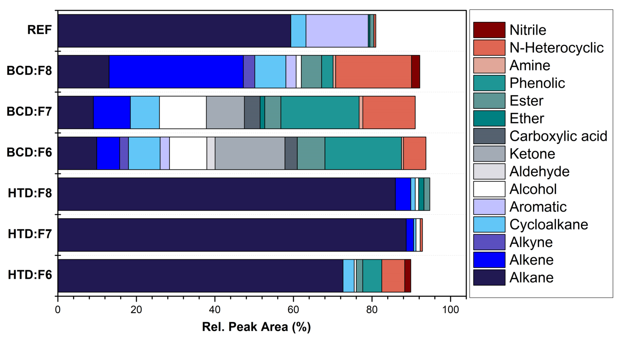
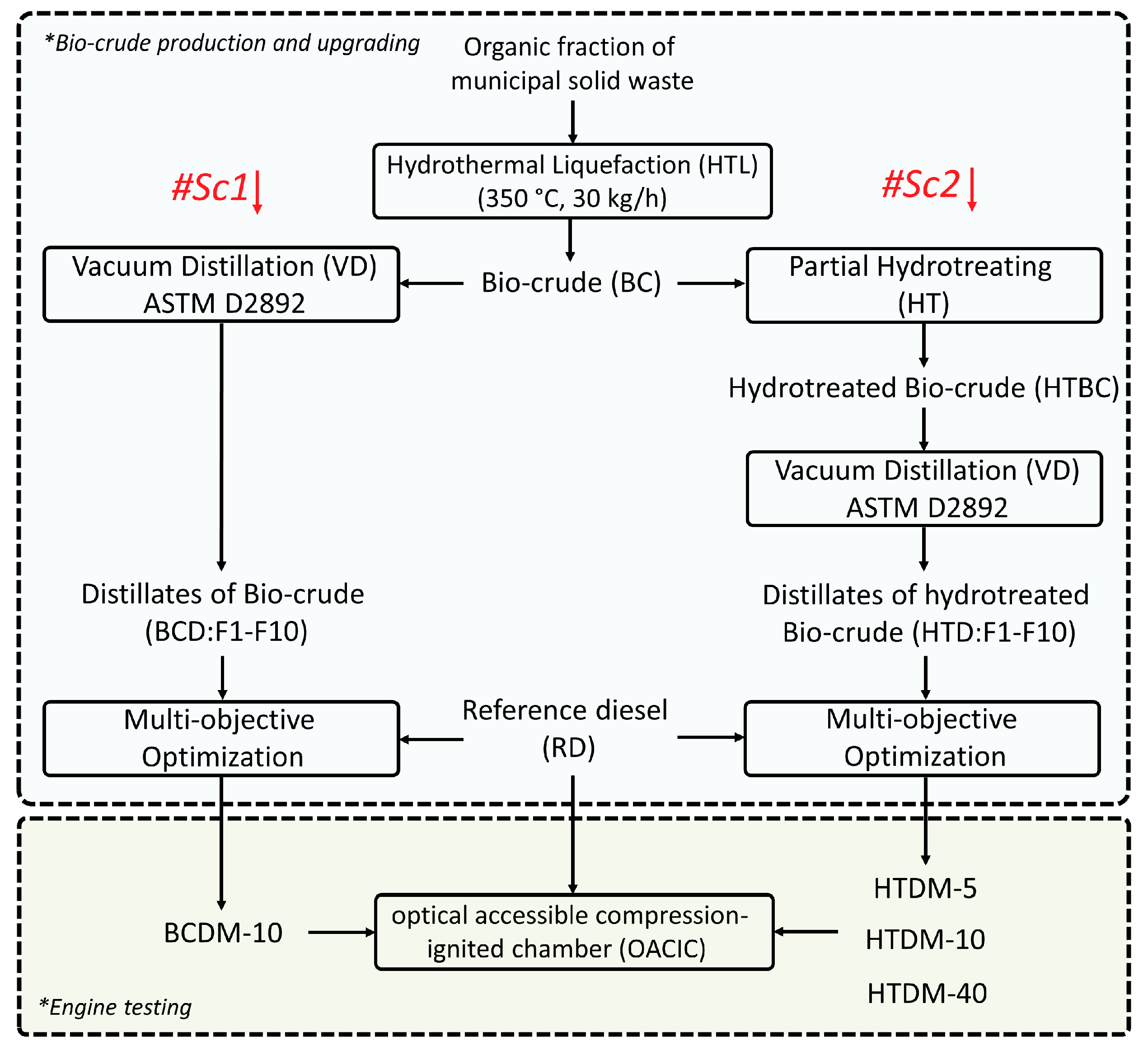
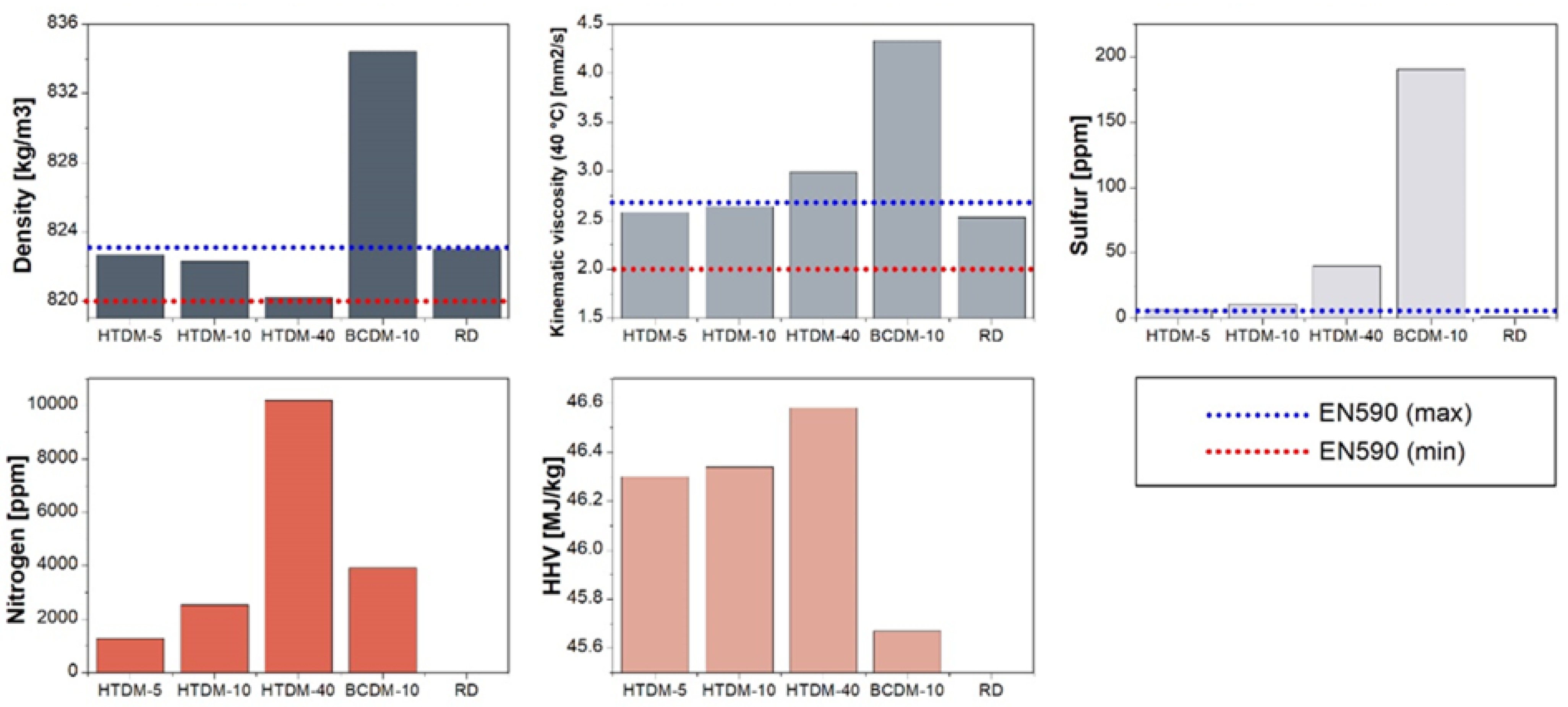
2.1. Fuel Production and Chemical Composition

The organic fraction of municipal solid waste was continuously processed in an HTL bench-scale unit at Aalborg University, Denmark. To obtain miscible HTL-based diesel blendstocks, two downstream process value chains were designed and the impact of each on the miscibility, physicochemical, and compositional properties of the fuels was thoroughly evaluated. The extensive elaboration and the results can be found in our previous study [23]. In brief, Scenario 1 (#Sc1) employed a vacuum distillation to fractionate the raw bio-crude (BC), whereas, in Scenario 2 (#Sc2), BC first underwent a partial hydrotreating stage (to obtain hydrotreated bio-crude (HTBC)) and the acquired fuel precursor was subjected to the vacuum distillation unit. The properties of the resultant distillation cuts (BCD: F1–F10 and HTD: F1–F10) were fully inspected. A multiobjective mathematical model was developed to compute: (1) the optimized mixture of biodistillate cuts (BCDM and HTDM), and (2) the blending of the optimized mixture with an ultra-low sulfur reference diesel (Coryton Fuels, UK) in accordance with EN590 standard road diesel specifications. A summary of the scenarios and the nomenclatures is shown in Figure 1.
The chemical composition of the reference diesel (RD/REF), BCD (F6–F8), and HTD (F6–F8), categorized based on organic functionalities was characterized through GC–MS and presented in Figure 2. The BCD: F6–F8 and HTD: F6–F8 reflect the diesel fraction. The alkene content is higher in upgraded HTL biofuel (HTDM) than RD and lower relative to nonupgraded HTL (BCDM). The consequences of this data will be explored and discussed in detail within the results section.

2.2. Fuel Selection and Parameters

In our previous study [23], a comprehensive elaboration on the topic is given. Here, a summarized overview is presented. Based on the multiobjective optimization results, 0.3 wt.% of contribution was detected for BCDM before reaching the first blending wall (sulfur content). On the contrary, HTDM with enhanced properties owing to the prestabilization step contributed over 5 wt. % to the final blend in respect to EN590 (denoted as HTDM5). Moreover, HTDM10 was found to comply with most of the required properties but with sulfur content (11.01 ppm). Hence, HTDM5 and HTDM10 were recognized as on-spec blend fuels and chosen to be studied. To specify the impact of blend fuel characteristics on the combustion and emission properties, two additional samples (BCDM10 and HTDM40) were also introduced to the combustion setup, and the relevant parameters were investigated. In summary, the upgraded HTL biofuel was blended with reference diesel (RD) by 5%, 10%, and 40% by weight (HTDM5, HTDM10, and HTDM40, respectively) and nonupgraded HTL biofuel was blended with RD by 10% by weight denoted as BCDM10. Figure 3 compares different blend fuel properties to the EN590 compliance region and the reference diesel fuel. The cetane index (CI) of RD, BCDM, and HTDM are 58.4, 75.33, and 68, respectively. The CI of upgraded HTL biofuel (HTDM) is higher than RD. The oxygen content in RD, BCDM, and HTDM are 0, 7.41, and 0 in weight %, respectively. The carbon content of all tested fuels is similar. The impact of this will be discussed in the results section.

2.3. Experimental Setup

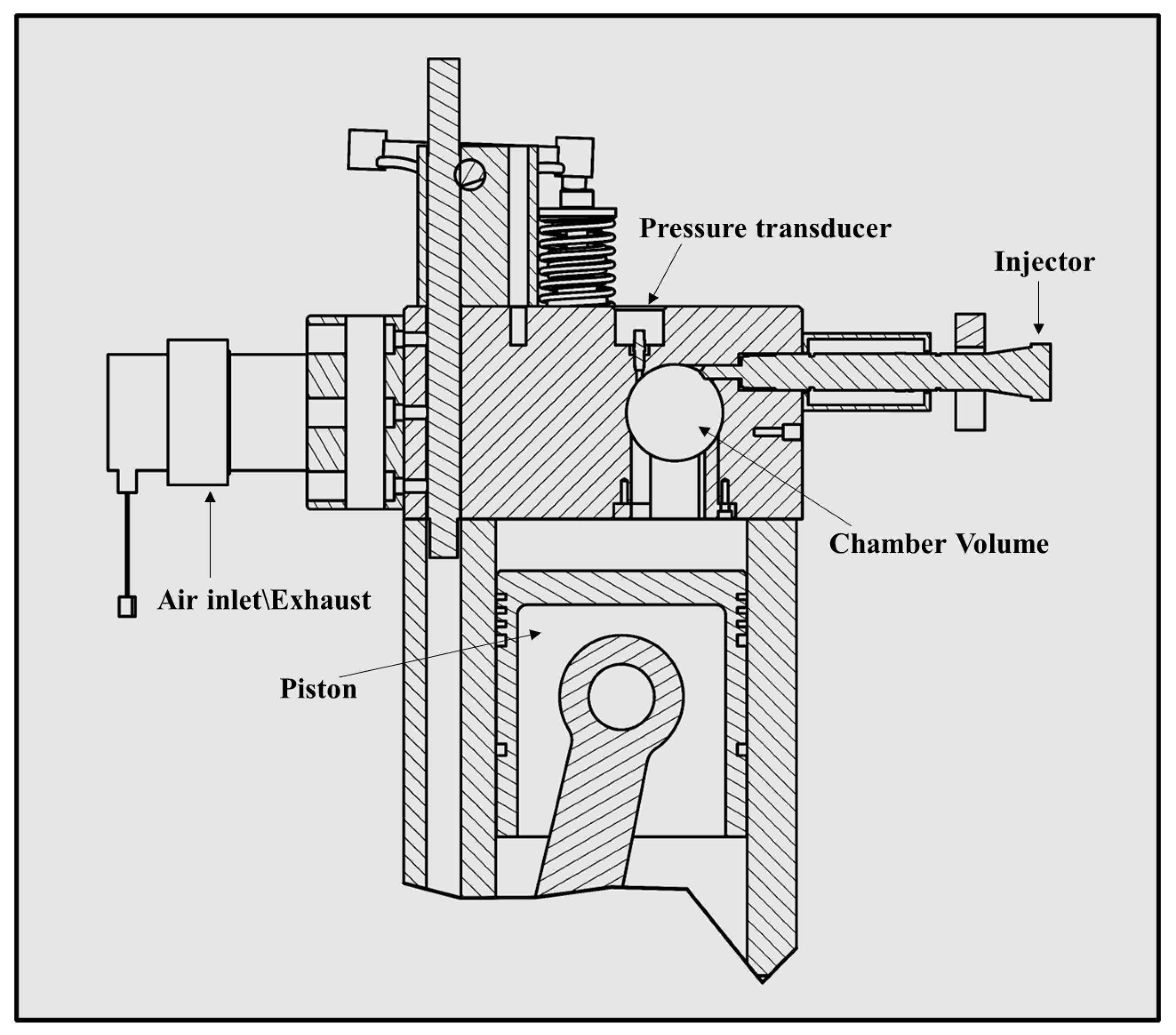
2.3.1. The Optical Accessible Compression Ignition Chamber (OACIC)

The experiments were carried out within the Optical Accessible Compression Ignition Chamber (OACIC), situated at the Motorlab, Department of Energy and Process Engineering, Norwegian University of Science and Technology (NTNU).The OACIC (Figure 4) is a modified 4-stroke engine (Lister 12 CS), with a restructured engine head to allow for access. The connection between the combustion chamber in the head and the engine’s swept volume is facilitated by an interchangeable throat. The intake and exhaust valves remain the same as the original engine and are installed in the modified engine head. The chamber is equipped with a Bosch solenoid common rail injector featuring a single-hole nozzle angled at 62° with respect to the nozzle axis. To prevent particulate matter (PM) emissions associated with engine oil, the OACIC is lubricated with light lubrication. The combustion chamber possesses a cylindrical configuration, featuring dimensions of 50 mm in diameter and 40 mm in height. This chamber is sealed with two fused silica windows, held in place by threaded rings, which provide a line-of-sight view into the chamber. A 500 rpm alternating current motor drives the piston and crank, with the crankshaft position determined by a magnetic shaft encoder. A dynamic pressure sensor, synchronized with the shaft encoder, diligently records both the motored and combustion pressures within the chamber. The engine head is not externally heated or cooled, while the engine cylinder is maintained at a constant temperature of 90 °C using heaters. Optical measurements are conducted using a skip fire mode, with at least ten motored cycles preceding each combustion cycle to ensure more stable thermal conditions during operation. Injection pressure is regulated by an air-driven pump, and the intake air system consists of a large air box with the volume flow rate of intake air measured using an orifice plate positioned inside the air box. The intake air is compressed by a root compressor, and an electric flow heater is located near the intake manifold. Further details of the engine can be found in Table 1, and a more comprehensive description of the OACIC is available in a previous publication [24].
For the zero-dimensional analysis of the chamber’s thermodynamic conditions, the first law approach was employed [25]. The calculation relied on inputs such as in-cylinder pressure, wall temperature, engine dimensions, inlet air temperature, and inlet air pressure. The iterative calculation of the in-cylinder temperature utilized the energy conservation equation and the ideal gas law. The specific thermodynamic conditions considered in this study were the intake pressure of 1.25 bar and the intake temperature of 55.3 °C. The ambient gas density at top dead center (TDC) was set at 16.5 kg/m3, while the ambient gas temperature at TDC was established at 827.4 K. More detailed information regarding the acquisition system, sensor precision, and uncertainty calculation can be found in our previous work [24]. The in-cylinder pressure data were recorded over 100 consecutive cycles with a sampling interval of approximately 0.15 crank angle degrees (CAD), and the mean value was used for calculations. The output signals from the pressure transducer were amplified and digitized. The heat release rate was determined from the in-cylinder combustion pressure, employing a first-law approach as described by Heywood [25]. The HRR quantifies the amount of heat energy produced per CAD during fuel combustion. The cumulative heat release rate (CHRR) was derived from the HRR data and represents the sum of heat released at each moment during the combustion process, measured as a function of crank angle degrees. The interval between the start of injection and the beginning of combustion, known as the ignition delay, was determined based on the HRR using the methodology outlined in Heywood [25]. Horiba MEXA-ONE-RS and Cambustion DMS 500 analyzers were utilized to measure exhaust gas concentration and particulate matter, respectively. Both analyzers incorporate heated lines and have a comparatively high sampling rate of 1 Hz.

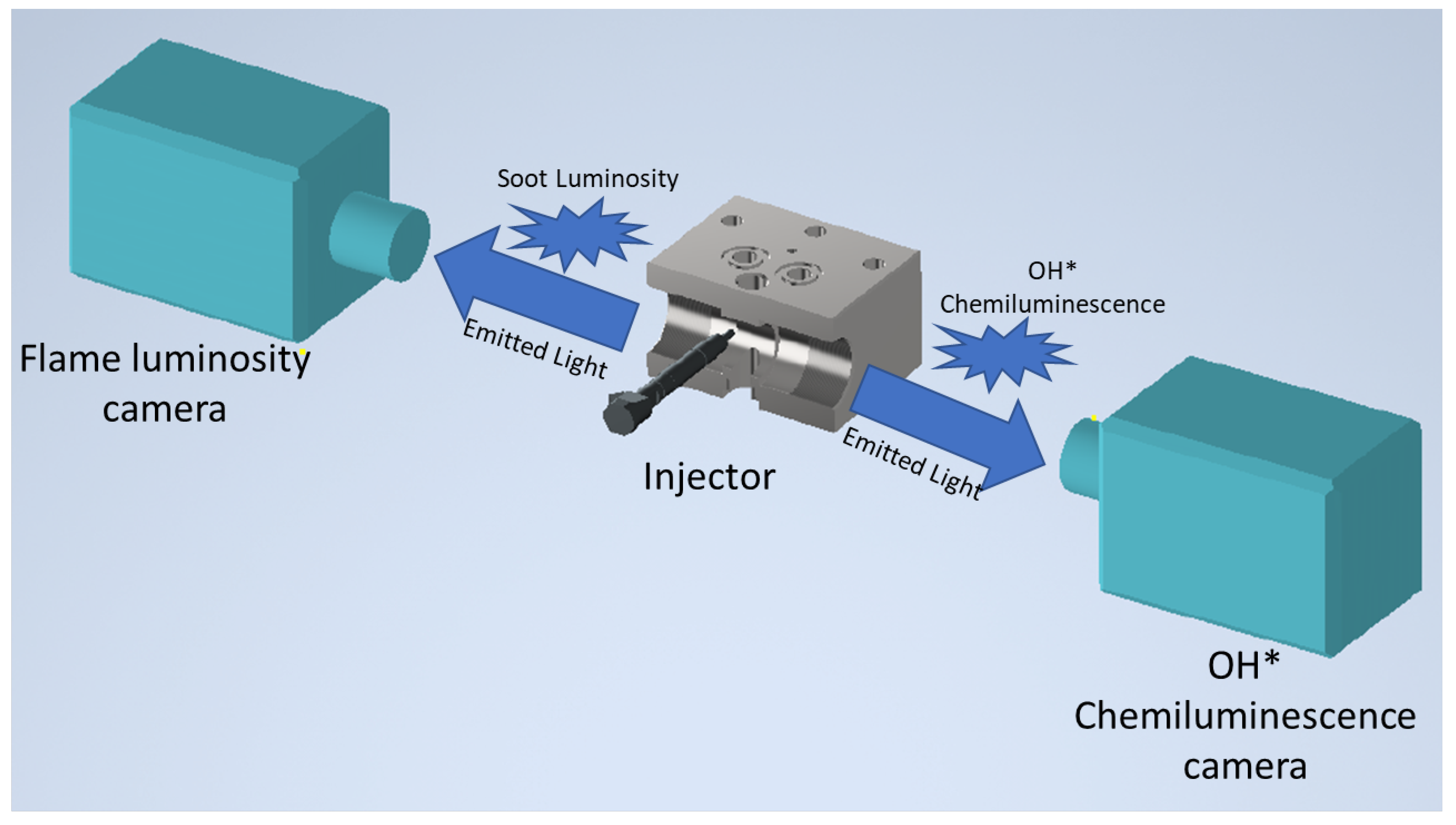
2.3.2. Optical Setup

The ID based on OH was determined from the OH* chemiluminescence measurements. The OH*-based ID refers to the specific period of time between the initiation of fuel injection and the first observed chemiluminescence signal of OH*. This measurement is utilized to gain insights into the overall combustion behavior of fuel under specific temperature and pressure conditions. On the other hand, the ID is a crucial parameter in combustion and engine design studies as it provides a measure of the time required for a combustible fuel–air mixture to react once it reaches a specific temperature and pressure. This reaction triggers the release of energy and the rapid formation of radicals, which can be captured by the OH* signal. The ID serves as a valuable benchmark for understanding the combustion characteristics and performance of fuels in combustion systems [24]. To capture the regions of high release rate within the flame, imaging was conducted using a narrow bandwidth in the ultraviolet (UV) spectrum centered at 310 nm with a bandwidth of 10 nm (full width at half maximum). The stoichiometric sections of the flame burn at high temperatures, leading to the formation of electronically excited hydroxide radicals (OH*), primarily through the reaction CH + O2→ CO + OH*. As OH* transitions back to the ground state OH, it emits radiation, which is particularly strong at around 310 nm. OH* chemiluminescence was measured using a high-speed camera (FASTCAM SA5, Photron) connected to a gated intensifier (HiCatt 18, Lambert Instruments BV, The Netherlands) equipped with a 105 mm Nikkor UV lens. The measurements were recorded at a rate of 25,000 frames per second (fps) with a resolution of 512 × 512 pixels, and the gate time was set to 20 μs.
The flame lift-off length is another critical parameter describing the distance between the fuel injection nozzle and the point at which the flame stabilizes within the combustion chamber, particularly during the diffusion combustion phase. Understanding the behavior of FLOL provides important insights into the efficiency of fuel and air mixing, which significantly impacts the combustion process, including its efficiency and pollutant emissions. In the case of a diffusion flame, the fuel and air are not premixed, unlike in premixed flame combustion. Instead, the fuel and oxidizer (typically air) remain separate until the combustion process occurs. Combustion takes place at the flame surface, where the fuel and oxidizer meet in the appropriate concentration, while the interior of the flame contains unburnt fuel. FLOL serves as a useful indicator of the extent and effectiveness of fuel–air mixing during the diffusion combustion phase. It represents the distance that the fuel spray travels before encountering an environment conducive to stable combustion. Consequently, a longer FLOL suggests suboptimal fuel and air mixing, resulting in incomplete combustion and higher levels of pollutant emissions. Conversely, a shorter FLOL indicates more favorable mixing conditions [26,27,28]. To analyze the behavior during the diffusion combustion period, the instantaneous FLOL was calculated by integrating the OH* intensity in each pixel column of the optical image and applying a threshold. Further details on the FLOL methodology can be found in our previous publication [29].
The natural flame luminosity method was employed to measure in-flame soot. This measurement was conducted using a high-speed camera (Photron FASTCAM NOVA 56) equipped with a Nikkor 50 mm f/1.2 lens, a 500D close-up lens, and neutral density filters to prevent camera saturation. All measurements were recorded at 25,000 fps, with an exposure time of 1.1 μs and a resolution of 384 × 384 pixels, and were synchronized to the OH* measurements. Natural flame luminosity consists of two constituent parts: chemiluminescence and soot luminosity. Within hydrocarbon flames, chemiluminescence emerges as a result of OH, CH, and C 2 radicals, which emit light within precise wavelength bands situated in the visible and near-ultraviolet spectrum. Conversely, soot luminosity originates from the thermal radiation emitted by soot particles, displaying a wide emission spectrum that varies based on soot concentration and temperature. Following ignition, it is common for soot luminosity to be similar to or even exceed the intensity of the chemiluminescence signal. It is evaluated by examining the spatial soot gradient (SSG) during the quasi-steady combustion phase at a fixed distance from the FLOL position. Assuming that the combustion plume travels at a uniform velocity regardless of the fuel used, the SSG acts as an informative parameter for assessing soot formation within the flame. To compute the SSG, the natural luminosity is integrated into each pixel column of the optical image and then graphed against the distance from the injector nozzle. This technique has been previously utilized by the authors [29]. The optical setup arrangement is illustrated in Figure 5.

3. Results and Discussion

3.1. Combustion Characteristics

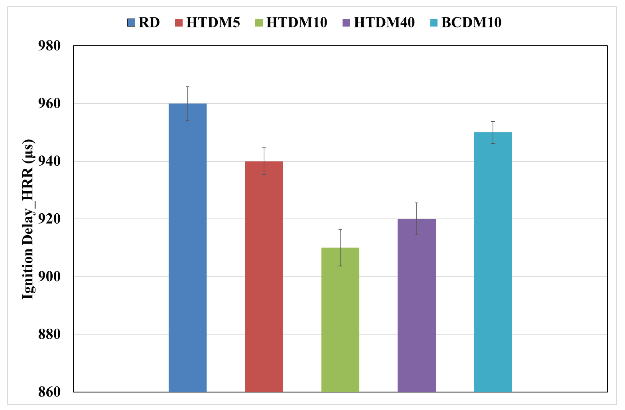
3.1.1. Heat Release Rate (HRR)

The heat release rate identifies three distinct combustion phases: ignition delay, premixed combustion, and diffusion combustion, as shown in Figure 6. The ID of upgraded HTL blends (HTDM) is shorter relative to the RD as the cetane index (CI) of upgraded HTL blends is higher. The higher fuel CI leads to shorter IDs because they have better autoignition properties, igniting more readily and quickly in response to the high temperatures and pressures [25]. The investigation by other authors [21,22] also showed a shorter ID for HTL blends relative to diesel. The ID of HTDM40 is slightly longer than HTDM10 because of the slightly higher viscosity of HTDM40. The higher viscosity can impact the atomization and vaporization processes, leading to a slower evaporation rate and, thus, increasing the physical ID. Additionally, the HTDM40 exhibits a higher CI compared to the HTDM10. A higher CI typically implies a shorter ID. However, in this particular case, the potential reduction in the chemically driven ID resulting from the higher CI may not compensate for the longer physical ID caused by the higher viscosity and slower evaporation rate. As a result, the HTDM40 experiences a slightly longer overall ID compared to the HTDM10 [30,31]. The ID of BCDM10 (nonupgraded) is longer relative to HTDM10 (upgraded) as its viscosity is higher. The ID of all the tested fuels can be observed in the zoomed part of Figure 6 and more clearly in Figure 7. The ID based on OH* chemiluminescence is also determined and illustrated in Figure 8. The ID based on OH* chemiluminescence shows a slight difference relative to the ID based on HRR, and is consistently longer by roughly 10%. The discrepancy in the ID measured using the HRR data and OH* chemiluminescence measurements can be attributed to the nature of the measurements and the specific processes they represent in the combustion system. HRR data are typically obtained from pressure and temperature measurements within the combustion chamber, providing an integrated view of combustion across the entire chamber volume. This means that HRR data account for the collective combustion reactions occurring in various zones of the combustion chamber, capturing the macroscopic behavior of the fuel–air mixture in the diesel engine [32]. In contrast, OH* chemiluminescence measurements capture specific chemical reaction pathways during the combustion process. OH* radicals are formed in high-temperature combustion reactions, and their light emissions serve as a proxy for heat release [33]. However, these measurements are sensitive to local conditions within the combustion chamber, including temperature, pressure, and mixture composition [34]. While both methods offer valuable insights into the combustion process, they have their limitations and are sensitive to different aspects of the combustion process. Hence, the slight disparity in the ID obtained from these two methods.
In the premixed phase, identified by the rapid increase and drop in HRR between −2 and 0 CAD in Figure 6, the upgraded HTL blends show a lower peak of HRR than that of the RD. The highest peak of HRR is obtained for the RD due to its longer ID, resulting in the accumulation of fuel, which burns at a higher rate during the premixed combustion phase leading to higher HRR peak values [22]. The HRR peak of BCDM10 is higher relative to HTDM10 because of the higher ID of BCDM10, but still remarkably comparable to HTDM despite not being upgraded. During the diffusion phase, between 0 and 6 CAD in Figure 6, the HRR of the upgraded HTL blends is lower than that of the RD. This is due to the slightly higher viscosity of the upgraded blends, which results in a slower mixing of fuel and air, eventually leading to lower HRR [35]. The HRR of BCDM10 is slightly higher relative to HTDM10, even though BCDM10 viscosity is higher; this could be due to the slight presence of oxygen content in BCDM10, which enhances the HRR of the fuel. Higher viscosity typically hinders the atomization and mixing of fuel droplets with air but if the oxygen content is sufficient, it may still outbalance this drawback. The oxygen atoms in the fuel help in breaking down the hydrocarbons more effectively, this leads to a more complete and rapid combustion, contributing to a higher HRR [36]. This effect can be more clearly observed by studying the cumulative heat release between 0 and 6 CAD in Figure 9.

3.1.2. In-Cylinder Pressure

The in-cylinder pressure results of all the tested fuels, along with the motored curve, are shown in Figure 10. In the premixed combustion phase (between −2 and 0 CAD), the rate of the pressure rise of the upgraded HTL blends is higher relative to the RD as their ID is shorter. The pressure rise of BCDM10 is lower relative to HTDM10 because of the longer ID of BCDM10. In the diffusion combustion phase (between 0 and 6 CAD), the peak cylinder pressure is similar for all the tested fuels.

3.1.3. Flame Lift-Off Length (FLOL)

The FLOL for all the fuels was determined based on the OH* chemiluminescence images. A sample size of 40 combustion cycles was utilized to obtain a statistically representative mean value. The mean temporal behavior of the FLOL is presented in Figure 11. The FLOL initially starts with larger values and then stabilizes at a shorter distance later in the cycle. This trend could potentially be attributed to the colder ambient gas temperatures prior to combustion. As the combustion progresses, the ambient gases become further compressed by the rise in combustion pressure, leading to an increase in temperature. This effect is likely to be responsible for the observed fluctuations in the FLOL within the combustion chamber as the combustion process itself is inherently stochastic. These variations are more pronounced in a small-volume combustion chamber, like the one used in this study, in contrast to a typical constant-volume combustion chamber with a larger chamber volume, where such fluctuations are less conspicuous. The FLOL stabilizes within the range of 2500 to 3500 μs after the start of injection (ASOI), which also corresponds to the quasi-steady period of the combustion process. Toward the end of this period, a slight increase in the FLOL is observed, which could be attributed to the decrease in ambient gas temperature during the expansion stroke. The average values of the FLOL during the quasi-steady period for all the fuels are illustrated in Figure 12. The FLOL of the upgraded HTL blends are consistently slightly shorter relative to the RD as also the ID of the upgraded blends is shorter. With a shorter ID, the combustion initiates closer to the fuel injector nozzle. Since the flame stabilizes near the point of combustion initiation, this leads to a shorter FLOL [29]. The FLOL of BCDM10 is slightly longer compared to HTDM10 because of its longer ID.

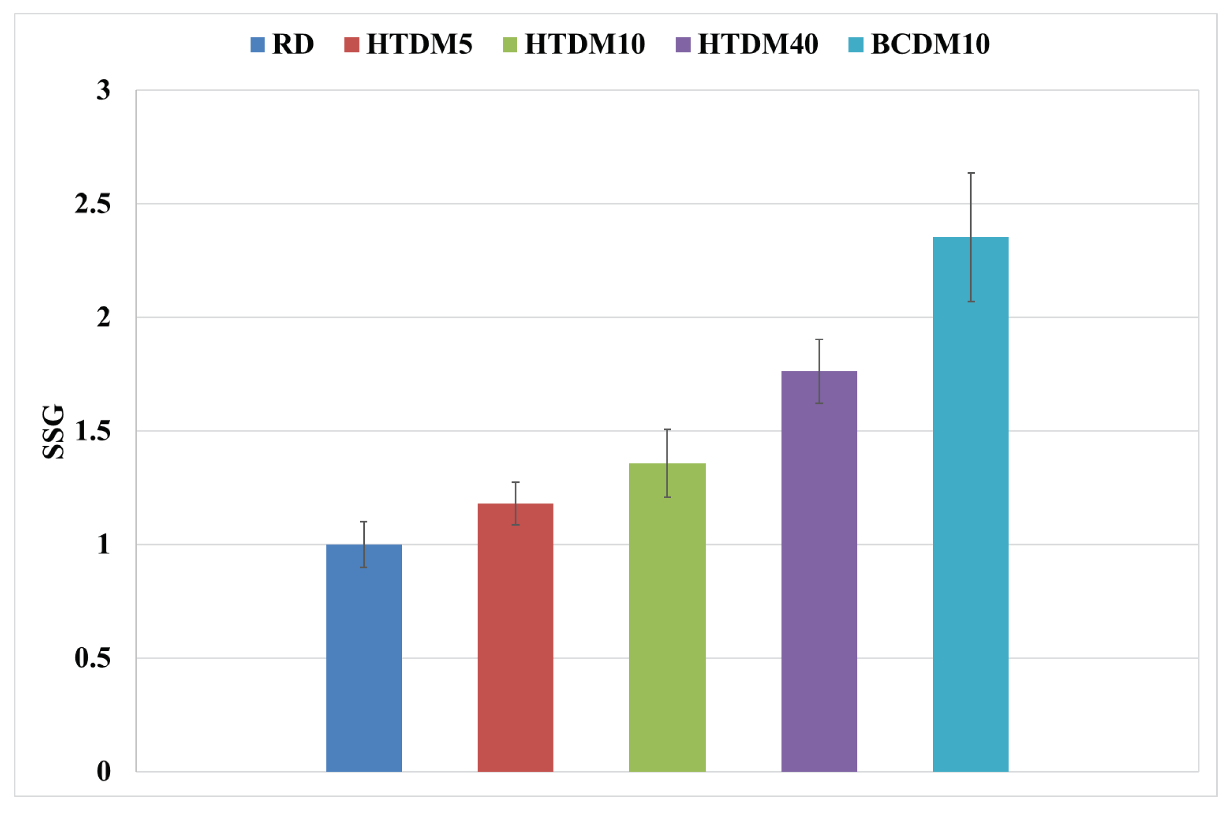
3.1.4. In-Flame Soot

Soot is essentially particulate matter resulting from incomplete combustion and is particularly associated with fuels having a higher carbon content. The formation of soot is a complex process that involves nucleation, growth, agglomeration, and oxidation stages. Several factors affect this, including the fuel’s chemical composition, combustion temperature, oxygen concentration, and engine operation conditions [25]. The in-flame soot results of all the tested fuels are shown in Figure 13 in terms of normalized spatial soot gradient (SSG) values. The upgraded HTL blends’ combustion generates higher in-flame soot relative to the RD. This could be due to the higher presence of alkenes in the upgraded HTL blends. Alkenes are unsaturated hydrocarbons that contain one or more carbon-carbon double bonds. Their structure makes them more prone to soot formation. The presence of double bonds provides additional reactive sites for the initiation of soot precursor formation during combustion, leading to an increased likelihood of soot formation [37,38]. A similar trend of in-flame soot for HTL blends was found by the authors in [21,22]. The in-flame soot of BCDM10 is higher relative to HTDM10 as it has a higher alkene content.
Figure 14 displays the optical images during a quasi-steady period for all the fuels tested. The images show both the FLOL and SSG for each fuel. The FLOL illustrates the distance at which the flame stabilizes, while the SSG depicts the variation in soot concentration at a fixed distance from the FLOL position. These images show combustion characteristics for the different fuels examined in this study.

3.2. Exhaust Emissions

Given that emissions data were collected during the experimental campaign, a brief summary of these findings is presented below.

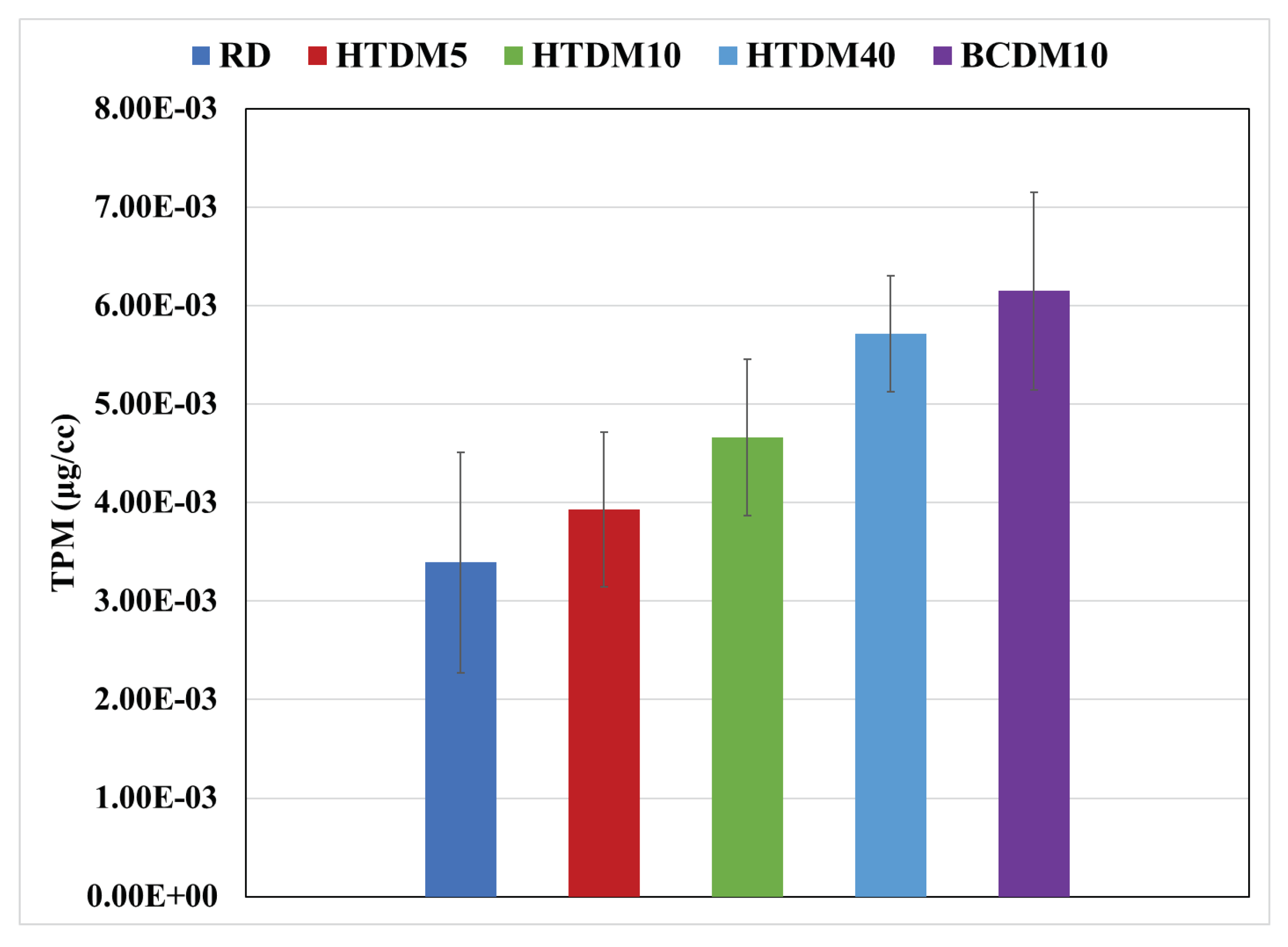
3.2.1. Particulate Matter (PM)

Particulate matter originates from the incomplete combustion of fuels. It consists of various substances, including carbonaceous materials, soot, metal compounds, and other organic and inorganic compounds. The PM was calculated in terms of total particulate mass (TPM). Figure 15 shows the TPM of all the tested fuels. The combustion of the upgraded HTL blends generates a higher TPM relative to the RD, attributed to the higher in-flame soot formation that takes place in the upgraded blends. The research work by [16,21,22] also showed higher PM emissions for HTL biofuel compared to diesel. The TPM of BCDM10 is, however, even higher, and significantly so relative to HTDM10 because of the higher formation of in-flame soot in BCDM10.

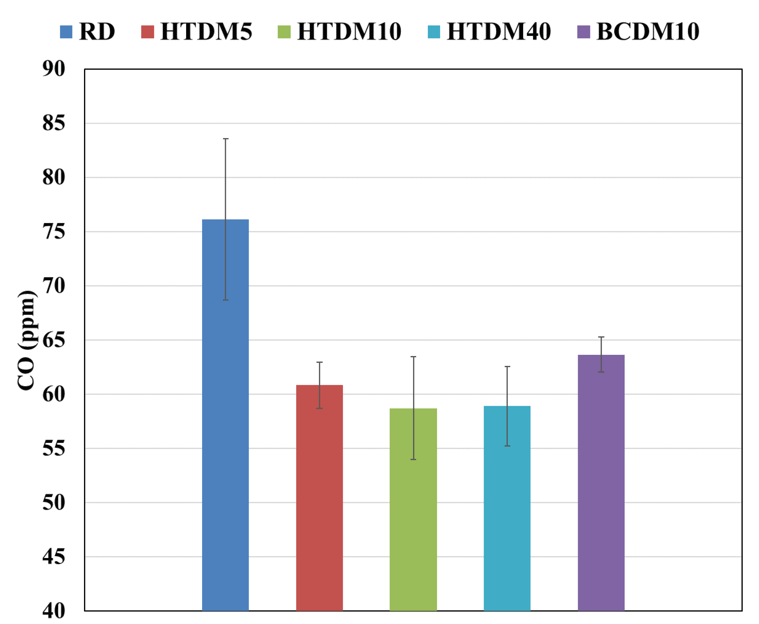
3.2.2. Carbon Monoxide (CO)

Carbon monoxide forms when fuel does not undergo complete combustion. The results of the CO emissions of all the tested fuels are plotted in Figure 16. The upgraded HTL blends emit less CO emissions compared to the RD. This is because of better combustion characteristics linked to its higher CI than the RD. Fuels with a higher CI are known to promote more efficient and complete combustion, reducing the likelihood of unburnt fuel being emitted as CO. In the case of the upgraded HTL blends, their higher CI would contribute to a more thorough combustion process, resulting in reduced CO emissions [16]. The findings of other authors [17,20,39] also followed a similar trend for CO emissions. Moreover, the higher alkene content in the upgraded HTL biofuel could also contribute to lower CO emissions. While alkenes are associated with increased soot due to their higher carbon content and reactivity, their unsaturated nature also allows them to react more readily with oxygen during combustion, which can lead to more complete combustion and, hence, less CO formation. The HTDM40 has slightly higher CO emissions relative to HTDM10 as the HTDM40 viscosity is higher. The higher viscosity makes it difficult to atomize spray and partial burning and eventually affects the air–fuel mixing process; it leads to locally rich mixtures that cause more CO due to the lack of O2 [40]. The CO emissions of BCDM10 are slightly higher relative to HTDM10. This is due to the higher viscosity of BCDM10 relative to HTDM10.

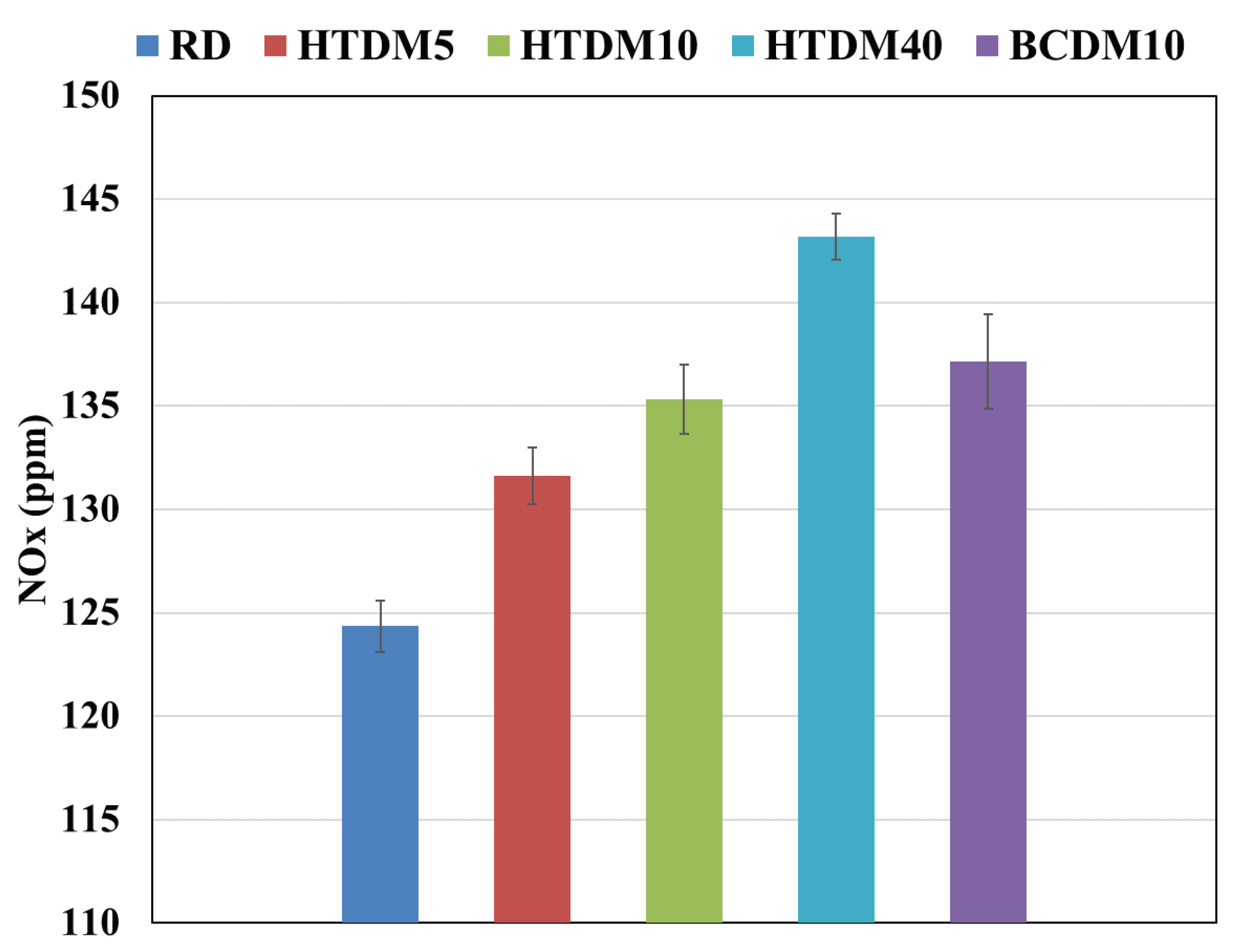
3.2.3. Nitrogen Oxides (NOx)

Fuel-bound NOx refers to when fuels containing nitrogen are burned; the nitrogen can be converted into nitrogen oxides during combustion, contributing to NOx emissions. The plot of the NOx emissions is shown in Figure 17. The upgraded HTL blends show higher NOx than the RD. In the upgraded HTL blends, the nitrogen content is higher than in the RD. During combustion, nitrogen in the fuel can react with oxygen in the air to form NOx. Therefore, the increased nitrogen content in the fuel could lead to higher NOx emissions [41,42]. The other investigations also found higher NOx emissions in the case of HTL biofuel relative to pure diesel due to higher nitrogen content in the HTL biofuel [20,39]. The NOx emissions of BCDM10 are higher relative to HTDM10 as the nitrogen content is higher in BCDM10. A detailed description of fuel-NOx and other-NOx formation mechanisms is available in Kohl et al. [43].

3.2.4. Carbon Dioxide Emissions (CO2)

The CO2 emissions are approximately similar for all the tested fuels. The similarity in CO2 emissions between the pure RD and the HTL biofuel blends can be attributed to the carbon content of the fuels. The combustion process in a diesel engine primarily involves the conversion of carbon in the fuel into CO2. Since both fuels have a similar carbon content per unit of mass, their combustion results in comparable quantities of CO2 emissions per unit of energy content. Therefore, the similar carbon content of the pure RD and the HTL biofuel blends accounts for the similarity in CO2 emissions during combustion [44]. The CO2 emissions of all the tested fuels is shown in Figure 18.

4. Conclusions

This present study focuses on the utilization of biofuel derived from municipal solid waste (MSW) in a compression ignition (CI) engine to showcase its potential as a renewable fuel. The biofuel was produced through the Hydrothermal Liquefaction (HTL) process, which was further upgraded. The influence of blending HTL biofuel with diesel on the combustion and emission characteristics was investigated in an optically accessible compression ignition chamber (OACIC) designed to simulate engine-like thermodynamic conditions. Furthermore, a comparative study between upgraded and nonupgraded HTL biofuels was conducted, assessing their impact on the combustion and emission features. The comprehensive findings from this investigation are as follows:
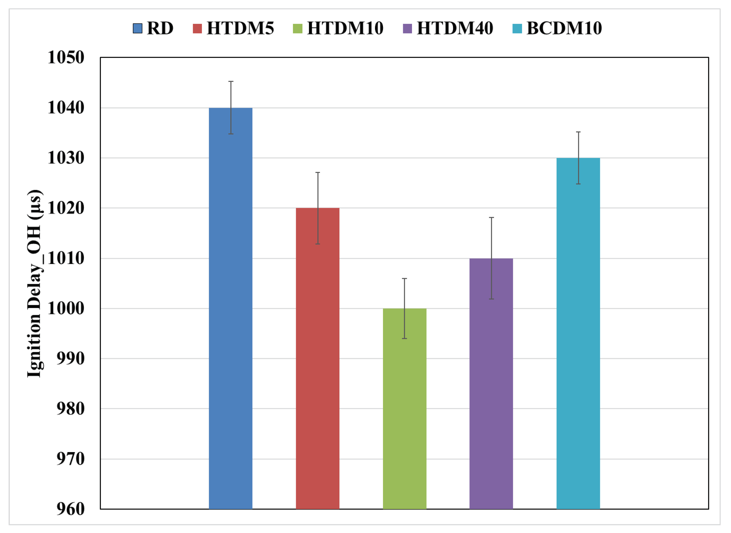
  • The ignition delay of the upgraded blends was shorter compared to the RD and nonupgraded blends but still within the range of engine optimization and operation control.
  • The peak in-cylinder pressure is similar for all the tested fuels.
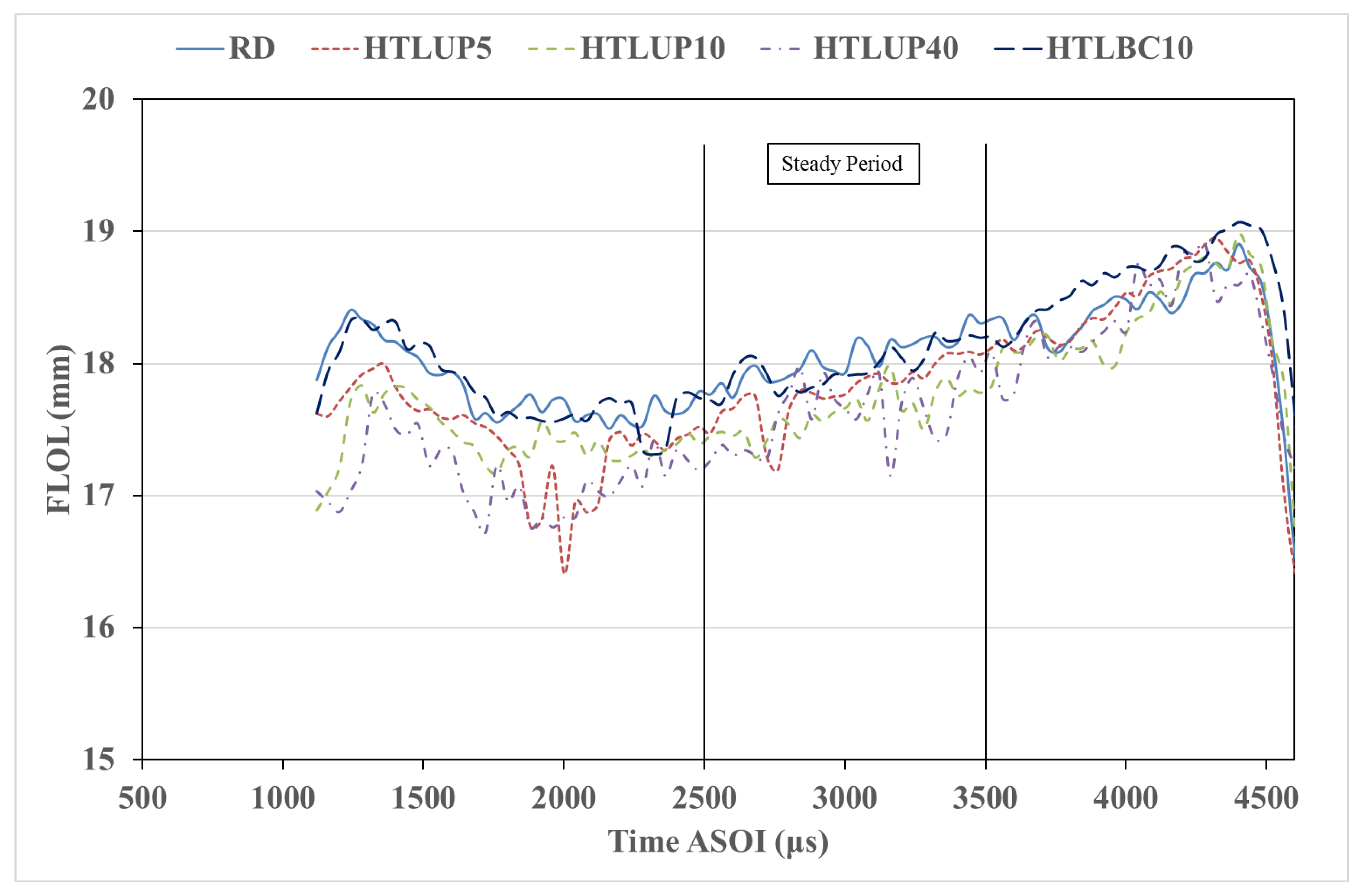
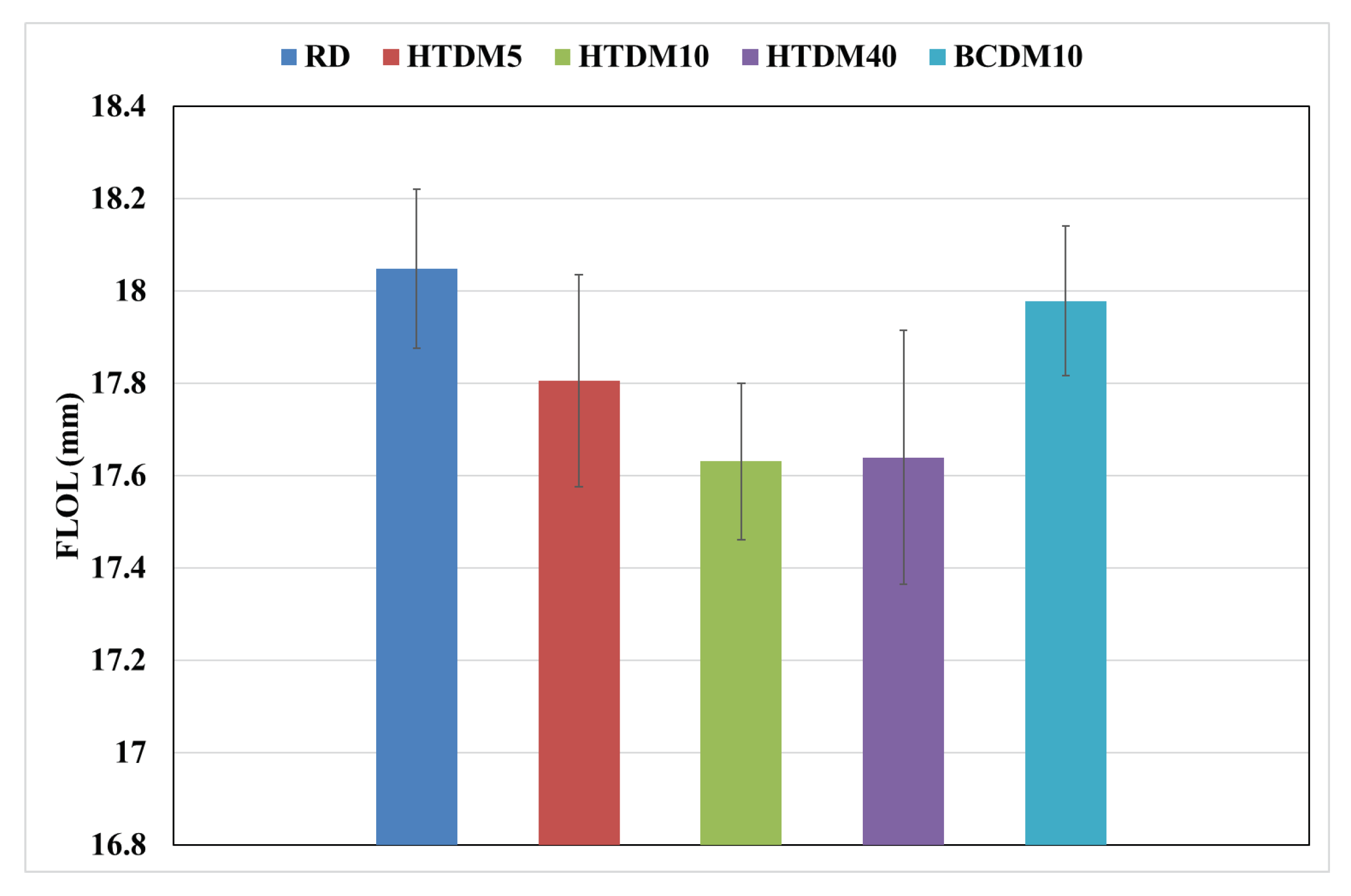
  • The flame lift-off length was shorter in the case of the upgraded blends than that of the RD and nonupgraded blends. The nonupgraded blends had the longest flame lift-off length, which can influence combustion efficiency.
  • The in-flame soot formation was higher for the upgraded blends compared to the RD and was less relative to the nonupgraded blend.
  • The PM emissions in terms of total particulate mass (TPM) were higher in the case of the upgraded blends compared to the RD and were lower relative to the nonupgraded blend.
  • The CO emissions were lower in the case of the upgraded blends compared to the RD and nonupgraded blends.
  • The NOx emissions were found to be higher for the upgraded blends relative to the RD and lower compared to the nonupgraded blend.
  • The CO2 emissions were found to be similar for all the tested fuels.
Overall, the HTL blends match the reference diesel to a large degree in terms of all the relevant combustion parameters and regulated emissions. The upgraded blend is found to have performed better relative to the nonupgraded blend, both in terms of combustion and emissions. However, the nonupgraded HTL fuel performs remarkably well in many respects, which may be a relevant finding for fuel manufacturers needing to make choices on production efficiency and market potential according to fuel quality requirements. The alkene content in the upgraded HTL biofuel should be reduced further in order to decrease the in-flame soot and PM emissions to perform better than the RD. Furthermore, the nitrogen content in the upgraded HTL biofuel also needs to be lowered to decrease the NOx emissions.

Author Contributions

Conceptualization, S.K., K.O.P.B., K.K. and T.L.; methodology, S.K., K.O.P.B., K.K., M.S.H. and D.C.; validation, K.O.P.B., T.H.P., T.L. and D.R.E.; formal analysis, S.K.; investigation, S.K., K.O.P.B. and K.K.; resources, T.H.P. and T.L.; data curation, S.K., K.O.P.B. and K.K.; writing—original draft preparation, S.K.; writing—review and editing, S.K., K.O.P.B., K.K., M.S.H., D.C., T.H.P., T.L. and D.R.E.; visualization, S.K.; supervision, T.H.P. and T.L.; project administration, T.L.; funding acquisition, T.H.P. and T.L. All authors have read and agreed to the published version of the manuscript.

Funding

The authors would like to acknowledge the financial support from Bio4Fuels (FME) of the Research Council of Norway, Project Number 257622. This project also received funding from the European Union’s Horizon 2020 Research and Innovation Programme under grant agreement no. 818413 (NextGenRoadFuels).

Data Availability Statement

Data will be made available on request.

Conflicts of Interest

The authors state that they have no known competing financial interests or personal relationships that could have influenced the work reported in this paper.

References

  1. United Nations Climate Change Conference UCC, Cop26 Glasgow Climate Pact. 2021. No. 28. Available online: https://unfccc.int/documents/310475 (accessed on 20 August 2023).
  2. Rehfeldt, M.; Worrell, E.; Eichhammer, W.; Fleiter, T. A review of the emission reduction potential of fuel switch towards biomass and electricity in European basic materials industry until 2030. Renew. Sustain. Energy Rev. 2020, 120, 109672. [Google Scholar] [CrossRef]
  3. Agarwal, A.K. Biofuels (alcohols and biodiesel) applications as fuels for internal combustion engines. Prog. Energy Combust. Sci. 2007, 33, 233–271. [Google Scholar] [CrossRef]
  4. Ahmed, S.; Warne, T.; Smith, E.; Goemann, H.; Linse, G.; Greenwood, M.; Kedziora, J.; Sapp, M.; Kraner, D.; Roemer, K.; et al. Systematic review on effects of bioenergy from edible versus inedible feedstocks on food security. NPJ Sci. Food 2021, 5, 9. [Google Scholar] [CrossRef] [PubMed]
  5. Lark, T.J.; Hendricks, N.P.; Smith, A.; Pates, N.; Spawn-Lee, S.A.; Bougie, M.; Booth, E.G.; Kucharik, C.J.; Gibbs, H.K. Environmental outcomes of the US Renewable Fuel Standard. Proc. Natl. Acad. Sci. USA 2022, 119, e2101084119. [Google Scholar] [CrossRef] [PubMed]
  6. Chen, H.; Su, X.; He, J.; Zhang, P.; Xu, H.; Zhou, C. Investigation on combustion characteristics of cyclopentanol/diesel fuel blends in an optical engine. Renew. Energy 2021, 167, 811–829. [Google Scholar] [CrossRef]
  7. Bleta, R.; Schiavo, B.; Corsaro, N.; Costa, P.; Giaconia, A.; Interrante, L.; Monflier, E.; Pipitone, G.; Ponchel, A.; Sau, S.; et al. Robust Mesoporous CoMo/γ-Al2O3 Catalysts from Cyclodextrin-Based Supramolecular Assemblies for Hydrothermal Processing of Microalgae: Effect of the Preparation Method. ACS Appl. Mater. Interfaces 2018, 10, 12562–12569. [Google Scholar] [CrossRef]
  8. Laredo, G.C.; Reza, J.; Meneses Ruiz, E. Hydrothermal liquefaction processes for plastics recycling: A review. Clean. Chem. Eng. 2023, 5, 100094. [Google Scholar] [CrossRef]
  9. Saengsuriwong, R.; Onsree, T.; Phromphithak, S.; Tippayawong, N. Biocrude oil production via hydrothermal liquefaction of food waste in a simplified high-throughput reactor. Bioresour. Technol. 2021, 341, 125750. [Google Scholar] [CrossRef]
  10. Kohansal, K.; Toor, S.; Sharma, K.; Chand, R.; Rosendahl, L.; Pedersen, T.H. Hydrothermal liquefaction of pre-treated municipal solid waste (biopulp) with recirculation of concentrated aqueous phase. Biomass Bioenergy 2021, 148, 106032. [Google Scholar] [CrossRef]
  11. He, P.; Chen, L.; Shao, L.; Zhang, H.; Lü, F. Municipal solid waste (MSW) landfill: A source of microplastics?—Evidence of microplastics in landfill leachate. Water Res. 2019, 159, 38–45. [Google Scholar] [CrossRef]
  12. Ramirez, J.A.; Brown, R.J.; Rainey, T.J. A review of hydrothermal liquefaction bio-crude properties and prospects for upgrading to transportation fuels. Energies 2015, 8, 6765–6794. [Google Scholar] [CrossRef]
  13. Sandquist, J.; Tschentscher, R.; del Alamo Serrano, G. Hydrothermal liquefaction of organic resources in biotechnology: How does it work and what can be achieved? Appl. Microbiol. Biotechnol. 2019, 103, 673–684. [Google Scholar] [CrossRef] [PubMed]
  14. Toor, S.S.; Rosendahl, L.; Rudolf, A. Hydrothermal liquefaction of biomass: A review of subcritical water technologies. Energy 2011, 36, 2328–2342. [Google Scholar] [CrossRef]
  15. Castello, D.; Pedersen, T.H.; Rosendahl, L.A. Continuous hydrothermal liquefaction of biomass: A critical review. Energies 2018, 11, 3165. [Google Scholar] [CrossRef]
  16. Chen, W.T.; Zhang, Y.; Lee, T.H.; Wu, Z.; Si, B.; Lee, C.F.F.; Lin, A.; Sharma, B.K. Renewable diesel blendstocks produced by hydrothermal liquefaction of wet biowaste. Nat. Sustain. 2018, 1, 702–710. [Google Scholar] [CrossRef]
  17. Hossain, F.M.; Nabi, M.N.; Rainey, T.J.; Bodisco, T.; Rahman, M.M.; Suara, K.; Rahman, S.M.; Van, T.C.; Ristovski, Z.; Brown, R.J. Investigation of microalgae HTL fuel effects on diesel engine performance and exhaust emissions using surrogate fuels. Energy Convers. Manag. 2017, 152, 186–200. [Google Scholar] [CrossRef]
  18. Hadhoum, L.; Zohra Aklouche, F.; Loubar, K.; Tazerout, M. Experimental investigation of performance, emission and combustion characteristics of olive mill wastewater biofuel blends fuelled CI engine. Fuel 2021, 291, 120199. [Google Scholar] [CrossRef]
  19. Nabi, M.N.; Rahman, M.M.; Islam, M.A.; Hossain, F.M.; Brooks, P.; Rowlands, W.N.; Tulloch, J.; Ristovski, Z.D.; Brown, R.J. Fuel characterisation, engine performance, combustion and exhaust emissions with a new renewable Licella biofuel. Energy Convers. Manag. 2015, 96, 588–598. [Google Scholar] [CrossRef]
  20. Obeid, F.; Van, T.C.; Horchler, E.J.; Guo, Y.; Verma, P.; Miljevic, B.; Brown, R.J.; Ristovski, Z.; Bodisco, T.; Rainey, T. Engine performance and emissions from fuels containing nitrogen and sulphur. Energy Convers. Manag. X 2022, 14, 100179. [Google Scholar] [CrossRef]
  21. Lee, T.H.; Yang, Z.; Zhang, Y.; Chen, W.T. Investigation of combustion and spray of biowaste based fuel and diesel blends. Fuel 2020, 268, 117382. [Google Scholar] [CrossRef]
  22. Yang, Z.; Lee, T.H.; Li, Y.; Chen, W.T.; Zhang, Y. Spray and combustion characteristics of pure hydrothermal liquefaction biofuel and mixture blends with diesel. Fuel 2021, 294, 120498. [Google Scholar] [CrossRef]
  23. Kohansal, K.; Lozano Sanchez, E.; Khare, S.; Oskar Pires Bjørgen, K.; Salman Haider, M.; Castello, D.; Løvås, T.; Aistrup Rosendahl, L.; Helmer Pedersen, T. Automotive sustainable diesel blendstock production through biocrude obtained from hydrothermal liquefaction of municipal solid waste. Fuel 2023, 350, 128770. [Google Scholar] [CrossRef]
  24. Bjørgen, K.O.P.; Emberson, D.R.; Løvås, T. Optical Measurements of In-Flame Soot in Compression-Ignited Methyl Ester Flames. Energy Fuels 2019, 33, 7886–7900. [Google Scholar] [CrossRef]
  25. Heywood, J. Internal Combustion Engine Fundamentals, 2nd ed.; McGraw-Hill Education: New York, NY, USA, 2018. [Google Scholar]
  26. Tao, C.; Liu, B.; Dou, Y.; Qian, Y.; Zhang, Y.; Meng, S. The experimental study of flame height and lift-off height of propane diffusion flames diluted by carbon dioxide. Fuel 2021, 290, 119958. [Google Scholar] [CrossRef]
  27. Wang, Q.; Hu, L.; Zhang, M.; Tang, F.; Zhang, X.; Lu, S. Lift-off of jet diffusion flame in sub-atmospheric pressures: An experimental investigation and interpretation based on laminar flame speed. Combust. Flame 2014, 161, 1125–1130. [Google Scholar] [CrossRef]
  28. Mei, Z.; Mi, J.; Wang, F.; Li, P.; Zhang, J. Chemical flame length of a methane jet into oxidant stream. Flow Turbul. Combust. 2015, 94, 767–794. [Google Scholar] [CrossRef]
  29. Emberson, D.R.; Wyndorps, J.; Ahmed, A.; Pires Bjørgen, K.O.; Løvås, T. Detailed examination of the combustion of diesel and glycerol emulsions in a compression ignition engine. Fuel 2021, 291, 120147. [Google Scholar] [CrossRef]
  30. Pham, P.X.; Pham, N.V.; Pham, T.V.; Nguyen, V.H.; Nguyen, K.T. Ignition delays of biodiesel-diesel blends: Investigations into the role of physical and chemical processes. Fuel 2021, 303, 121251. [Google Scholar] [CrossRef]
  31. Miron, L.; Chiriac, R.; Brabec, M.; Bădescu, V. Ignition delay and its influence on the performance of a Diesel engine operating with different Diesel–biodiesel fuels. Energy Rep. 2021, 7, 5483–5494. [Google Scholar] [CrossRef]
  32. Mustayen, A.G.; Wang, X.; Rasul, M.G.; Hamilton, J.M.; Negnevitsky, M. Thermodynamic analysis of diesel engine ignition delay under low load conditions. Energy Rep. 2022, 8, 495–501. [Google Scholar] [CrossRef]
  33. Sardeshmukh, S.; Bedard, M.; Anderson, W. The use of OH* and CH* as heat release markers in combustion dynamics. Int. J. Spray Combust. Dyn. 2017, 9, 409–423. [Google Scholar] [CrossRef]
  34. He, L.; Guo, Q.; Gong, Y.; Wang, F.; Yu, G. Investigation of OH* chemiluminescence and heat release in laminar methane–oxygen co-flow diffusion flames. Combust. Flame 2019, 201, 12–22. [Google Scholar] [CrossRef]
  35. Giuliano Albo, P.A.; Lago, S.; Wolf, H.; Pagel, R.; Glen, N.; Clerck, M.; Ballereau, P. Density, viscosity and specific heat capacity of diesel blends with rapeseed and soybean oil methyl ester. Biomass Bioenergy 2017, 96, 87–95. [Google Scholar] [CrossRef]
  36. Altarazi, Y.S.; Abu Talib, A.R.; Yu, J.; Gires, E.; Abdul Ghafir, M.F.; Lucas, J.; Yusaf, T. Effects of biofuel on engines performance and emission characteristics: A review. Energy 2022, 238, 121910. [Google Scholar] [CrossRef]
  37. Zhou, C.W.; Farooq, A.; Yang, L.; Mebel, A.M. Combustion chemistry of alkenes and alkadienes. Prog. Energy Combust. Sci. 2022, 90, 100983. [Google Scholar] [CrossRef]
  38. Yin, Y.; Medwell, P.R.; Gee, A.J.; Foo, K.K.; Dally, B.B. Fundamental insights into the effect of blending hydrogen flames with sooting biofuels. Fuel 2023, 331, 125618. [Google Scholar] [CrossRef]
  39. Obeid, F.; Van, T.C.; Horchler, E.J.; Guo, Y.; Verma, P.; Miljevic, B.; Brown, R.J.; Ristovski, Z.; Bodisco, T.A.; Rainey, T. Engine performance and emissions of high nitrogen-containing fuels. Fuel 2020, 264, 116805. [Google Scholar] [CrossRef]
  40. Santhosh, K.; Kumar, G.N. Impact of 1-Hexanol/diesel blends on combustion, performance and emission characteristics of CRDI CI mini truck engine under the influence of EGR. Energy Convers. Manag. 2020, 217, 113003. [Google Scholar] [CrossRef]
  41. Szybist, J.P.; Kirby, S.R.; Boehman, A.L. NOx emissions of alternative diesel fuels: A comparative analysis of biodiesel and FT diesel. Energy Fuels 2005, 19, 1484–1492. [Google Scholar] [CrossRef]
  42. Vieira da Silva, M.A.; Lagnier Gil Ferreira, B.; da Costa Marques, L.G.; Lamare Soares Murta, A.; Vasconcelos de Freitas, M.A. Comparative study of NOx emissions of biodiesel-diesel blends from soybean, palm and waste frying oils using methyl and ethyl transesterification routes. Fuel 2017, 194, 144–156. [Google Scholar] [CrossRef]
  43. Kohl, A.L.; Nielsen, R.B. Control of Nitrogen Oxides. Gas Purif. 1997, 866–945. [Google Scholar] [CrossRef]
  44. Elkelawy, M.; Alm-Eldin Bastawissi, H.; El Shenawy, E.A.; Taha, M.; Panchal, H.; Sadasivuni, K.K. Study of performance, combustion, and emissions parameters of DI-diesel engine fueled with algae biodiesel/diesel/n-pentane blends. Energy Convers. Manag. X 2021, 10, 100058. [Google Scholar] [CrossRef]
Figure 1. Schematic summary from biomass to combustible blend diesel.
Energies 16 06754 g001
Figure 2. Chemical composition of RD/REF, BCD, and HTD categorized based on organic functionalities.
Energies 16 06754 g002
Figure 3. Measured blend fuel specifications in comparison to the reference diesel and EN590 required standards.
Energies 16 06754 g003
Figure 4. OACIC cross-sectional view.
Energies 16 06754 g004
Figure 5. Optical setup around the OACIC.
Energies 16 06754 g005
Figure 6. Heat release rate with crank angle degree.
Energies 16 06754 g006
Figure 7. Ignition delay based on HRR.
Energies 16 06754 g007
Figure 8. Ignition delay based on OH.
Energies 16 06754 g008
Figure 9. Cumulative heat release rate versus crank angle degree.
Energies 16 06754 g009
Figure 10. Cylinder pressure plot versus crank angle degree.
Energies 16 06754 g010
Figure 11. Ensemble-averaged flame lift-off length over time for all fuels.
Energies 16 06754 g011
Figure 12. Average FLOLs during the quasi-steady period.
Energies 16 06754 g012
Figure 13. Spatial soot gradient for all tested fuels.
Energies 16 06754 g013
Figure 14. Optical images showing FLOL and SSG for different fuels.
Energies 16 06754 g014
Figure 15. Total particulate mass of all tested fuels.
Energies 16 06754 g015
Figure 16. Carbon monoxide emissions of all tested fuels.
Energies 16 06754 g016
Figure 17. Nitrogen oxides emissions of all tested fuels.
Energies 16 06754 g017
Figure 18. Carbon dioxide emissions of all tested fuels.
Energies 16 06754 g018
Table 1. OACIC Engine specifications.
Engine TypeFour-stroke, single cylinder, indirect DI engine
Bore/stroke130 mm/140 mm
Displaced volume1.85 L
Compression ratio (CR)16.36
InjectorBosch CR second generation
Injector nozzleSingle hole, 62 deg wrt central axis
Hole diameter0.12 mm
Injection pressure1000 bar
Injection duration5 ms
Injection timing4 CAD before top dead center (BTDC)
Speed500 rpm
Disclaimer/Publisher’s Note: The statements, opinions and data contained in all publications are solely those of the individual author(s) and contributor(s) and not of MDPI and/or the editor(s). MDPI and/or the editor(s) disclaim responsibility for any injury to people or property resulting from any ideas, methods, instructions or products referred to in the content.

