Article

Numerical Analysis of Dual Fuel Combustion in a Medium Speed Marine Engine Supplied with Methane/Hydrogen Blends

by
Maria Cristina Cameretti
,
Roberta De Robbio
* and
Marco Palomba
Department of Industrial Engineering, University of Naples Federico II, Via Claudio 21, 80125 Naples, Italy
*
Author to whom correspondence should be addressed.
Energies 2023, 16(18), 6651; https://doi.org/10.3390/en16186651
Submission received: 9 August 2023 / Revised: 1 September 2023 / Accepted: 13 September 2023 / Published: 16 September 2023

Abstract

:
Compression ignition engines will still be predominant in the naval sector: their high efficiency, high torque, and heavy weight perfectly suit the demands and architecture of ships. Nevertheless, recent emission legislations impose limitations to the pollutant emissions levels in this sector as well. In addition to post-treatment systems, it is necessary to reduce some pollutant species, and, therefore, the study of combustion strategies and new fuels can represent valid paths for limiting environmental harmful emissions such as CO2. The use of methane in dual fuel mode has already been implemented on existent vessels, but the progressive decarbonization will lead to the utilization of carbon-neutral or carbon-free fuels such as, in the last case, hydrogen. Thanks to its high reactivity nature, it can be helpful in the reduction of exhaust CH4. On the contrary, together with the high temperatures achieved by its oxidation, hydrogen could cause uncontrolled ignition of the premixed charge and high emissions of NOx. As a matter of fact, a source of ignition is still necessary to have better control on the whole combustion development. To this end, an optimal and specific injection strategy can help to overcome all the before-mentioned issues. In this study, three-dimensional numerical simulations have been performed with the ANSYS Forte® software (version 19.2) in an 8.8 L dual fuel engine cylinder supplied with methane, hydrogen, or hydrogen–methane blends with reference to experimental tests from the literature. A new kinetic mechanism has been used for the description of diesel fuel surrogate oxidation with a set of reactions specifically addressed for the low temperatures together with the GRIMECH 3.0 for CH4 and H2. This kinetics scheme allowed for the adequate reproduction of the ignition timing for the various mixtures used. Preliminary calculations with a one-dimensional commercial code were performed to retrieve the initial conditions of CFD calculations in the cylinder. The used approach demonstrated to be quite a reliable tool to predict the performance of a marine engine working under dual fuel mode with hydrogen-based blends at medium load. As a result, the system modelling shows that using hydrogen as fuel in the engine can achieve the same performance as diesel/natural gas, but when hydrogen totally replaces methane, CO2 is decreased up to 54% at the expense of the increase of about 76% of NOx emissions.

1. Introduction

Marine transportation offers several advantages such as large carrying capacity, high safety, and low operating costs compared to other modes of transportation. However, despite these benefits, the significant emissions of nitrogen oxides (NOx), particulate matter (PM), and sulfur oxides (SOx) from marine diesel engines have resulted in serious environmental pollution in ports and coastal areas [1]. Usually, the quality of the fuel used in marine applications is lower than that used in automotive ones, and this favors pollutants and greenhouse gas emissions. As a matter of fact, several studies indicated that ship emissions, including NOx, SO2, and CO2, account for 15%, 4–9%, and 2.7% of global emissions, respectively [2]. For this reason, to limit pollutants in air and sea, even more stringent international regulations in the naval field are mandatory. In particular, merchant ships are subject to International Maritime Organization (IMO) regulations. The legislation defines NOx and SOx emission limits for diesel engine exhaust gases as a function of the engine speed and fuel sulfur content. The IMO has established emission standards known as Tier I, Tier II, and Tier III standards. The Tier I standards were initially defined in the 1997 version of Annex VI, while the Tier II/III standards were introduced through amendments in 2008. Tier I and Tier II emission limits are imposed at a global level, while the Tier III standards are enforced within designated Emission Control Areas (ECAs) [3,4]. An ECA can be established to regulate emissions of SOx and PM, NOx, or all three types of emissions from ships. Table 1 provides the NOx emission limits set by MARPOL Annex VI for marine diesel engines with a power output exceeding 130 kW, based on engine speed.
IMO set a further reduction of such emissions for 2025, and in order to meet such increasingly stringent regulations, three primary strategies are employed on marine diesel engines: exhaust gas aftertreatment, in-cylinder purification, and fuel technologies.
Exhaust gas aftertreatment techniques have proved to be effective in reducing emissions without significant impact on engine power and fuel economy. Selective catalytic reduction (SCR) systems are utilized to decrease nitrogen oxide emissions on various ship engines [6], while diesel particulate filters (DPF) are employed to remove particulate matter emissions [7]. However, since usually marine engines burn heavy fuel oils (HFOs), which contain high concentrations of sulfur, such devices must be made of resistant materials. For these reasons, larger vessels often incorporate scrubbers as aftertreatment devices to effectively reduce sulfur oxide emissions as well [8]. In terms of in-cylinder purification, this approach aims mainly to optimize combustion and reduce emissions [9], i.e., the addition of water [10], and the exhaust gas recirculation (EGR) [11,12]. Finally, clean fuels, in different proportions, play a crucial role in emissions reduction [13]. Currently, the main commercially available alternative fuels for marine diesel engines include biodiesel [14], natural gas [15,16], and methanol [17]. Nevertheless, the use of such fuels should be implemented with as few changes as possible on the existing engines to avoid high costs. Therefore, fuel technologies are the third path to follow for the emissions reduction in marine applications.
Ship engines operating in dual fuel (DF) mode stand out as one of the most promising solutions for implementing alternative fuels in the maritime industry [18]. Indeed, it is widely employed in various types of vessels, such as liquefied natural gas (LNG) carriers, container ships, and Ro-Ro ships [19]. One of the possible configurations foresees to deliver the alternative “primary” fuel to the intake ports or cylinders for combustion. In addition, a second fuel, referred to as the “pilot” or “secondary” fuel (usually diesel fuel), is introduced in the combustion chamber in small quantities to aid the starting of the combustion of the primary fuel. Although DF technology has become firmly established in naval applications, studies are still conducted today to improve the performance of the engines [20]. Indeed, DF engines are usually affected by unburned methane in the exhaust (methane slip) due to the incomplete combustion of this species, which features a high global warming potential (GWP) [21]. In order to mitigate such a phenomenon, EGR [22] and an effective management of the start of injection (SOI) of the fuel directly introduced in the combustion chamber [23] can be valid solutions.
Valladolid et al. [24] carried out an experimental campaign on an 8.8 L single-cylinder Wärtsilä 20DF engine to deepen the knowledge on the interaction between the primary fuel and highly reactive one used to ignite the mixture. In particular, they investigated the ignition characteristics of diesel fuel in NG-air mixtures by evaluating the link between the SOI and the effective start of combustion (SOC). Altinkurt et al. [25] compared the effects of single and split pilot injection, showing that for early injection strategies, a single injection can be beneficial for the combustion development, enabling a more homogeneous distribution of temperature inside the cylinder and a more uniform oxidation of methane. Cong et al. [26] evaluated the effect of a post-injection strategy of the pilot fuel. They demonstrated that with an optimized delayed post-injection, it is possible to minimize the NOx, avoiding a significant loss of performance. Yu et al. [27] investigated the performance and emissions of a marine low-speed, two-stroke engine by varying the direct natural gas (NG) injection timing from 8°BTDC to 2°BTDC. As per usual for diesel injection, a more advanced injection of NG as well leads to the enhancement of thermal efficiency and power and lower CH4 emissions but an increase of NOx.
Among the range of primary fuels available, hydrogen is gaining considerable attention in the automotive field due to its potential for low carbon emissions. In particular, the sustainability of compression ignition engines can be improved considerably [28,29]. Therefore, to mainly reduce CH4 in the exhaust, the maritime sector is going down the same path [30]. Consequently, some research attempts are directing their efforts towards the study of diesel and hydrogen combustion in marine engines for dual fuel applications. In order to avoid knocking and abnormal combustion events, Abdelhameed and Tashima [31] evaluated the performance of methane–hydrogen blends as the primary fuel in a marine diesel engine. Since the mixture of hydrogen and methane was directly injected, they also tested different injection pressures. The addition of H2 leads to a reduced jet penetration, an increased in-cylinder pressure, and an improved combustion efficiency, which means fewer unburned hydrocarbons (UHC). Hydrogen engines working in dual-fuel mode seem to have the same or better overall performance in terms of efficiencies, power, and emissions, with a high hydrogen fraction [32,33]. Due to the demands for high power densities and low CO2 for future shipping, hydrogen-enriched fuel engines for maritime applications can be an important topic of research. Together with hydrogen, another carbon-neutral fuel such as ammonia is expected to be a valid option for future low-carbon shipping, although an increase in NOx with respect to other fuels has been observed [28].
The aim of the CFD study carried out in the present paper is to numerically investigate the performance and emissions of an 8.8 L dual fuel cylinder Wärtsilä 20DF engine. Starting from the experimental data obtained from Reference [24], the numerical model has been calibrated for methane–diesel dual fuel case study. Due to the lack of complete experimental data on dual fuel diesel/methane enriched with hydrogen or diesel/hydrogen operation for medium and large bore engines, the aim and the novelty of this work are to analyse the behavior of these alternative solutions, which means several hydrogen–methane blends, including the extreme case of 100% H2; therefore, establishing the actual limits in terms of pollutant formation is necessary.
The authors of the present work already have experience in 3D numerical simulations concerning dual fuel engines, using natural gas (or methane) on light-duty [34] and heavy-duty engines [35] for different operating conditions of load and speed [36,37]. Instead, the more recent activity has been addressed to the study of hydrogen–methane blends [38,39].
The main difficulties of a DF CFD numerical analysis are related to the correct description of the oxidation of all the fuels involved in the combustion process. Indeed, it is necessary to utilize a kinetic mechanism and a combustion model capable of simulating the different phases of the dual fuel combustion, especially the autoignition of diesel fuel, which is responsible for the ignition of the primary fuel. It should also be considered that hydrogen has demonstrated a tendency for abnormal combustion events [40]. Moreover, the choice of the diesel surrogate often depends on the application investigated; in literature, researchers mainly use n-heptane (n-C7H16) [41,42], while the liquid properties can be represented by tetradecane (C14H30) [43]. However, all agree that the best-suited models for the description of atomization are the Kelvin–Helmholtz and Rayleigh–Taylor (KHRT).
Nevertheless, following their previous studies [35,36,39] in which the authors used n-dodecane (n-C12H26), in this work, a new kinetic mechanism is introduced by merging the scheme proposed by Ranzi et al. [44] for n-C12H26 oxidation with particular attention to the reactions occurring at low temperature, and the well-known GRIMECH 3.0 to account for the oxidation of the gaseous fuels (both CH4 and H2).
In the present investigation, the combustion evolution is studied in a medium displacement marine engine with several percentages of hydrogen substitution: 10%, 30%, 50%, 60%, and 100%. Starting from a reference case from literature, an integrated 0D/3D methodology was used to obtain the information about pressure and combustion development for the 100% CH4 case. A new kinetics mechanism was introduced to fairly describe the different phases of dual combustion, suitable for methane, hydrogen, and their blends when used as the primary fuel. Results demonstrate that an increasing hydrogen amount has positive effects on the reduction of CO2 and unburned hydrocarbon emissions. On the contrary, without the utilization of EGR and abatement systems, nitrogen oxides can dramatically exceed the current regulations.

2. Methodology

The authors utilized a numerical methodology based on 1D–3D modelling with the aim to predict the combustion development and emissions formation by varying the low reaction fuels amount through several CH4/H2 blend ratios and deepening the interaction between the high-reactivity (HRF) and the low-reactivity fuels (LRF) during the ignition process.
The investigation can be divided in two phases:
  • At first, a one-dimensional software based on thermo-fluid dynamics is used as a tool to recreate the behavior of the overall engine. Indeed, the one-dimensional code can perform several test cases by varying different engine parameters, and it can be used to provide the initial conditions to the CFD model for a more detailed in-cylinder study of the cases considered more significant. This approach was already used by the authors as it has demonstrated to be robust and reliable [45]. The reference case for engine calibration burns natural gas as LRF.
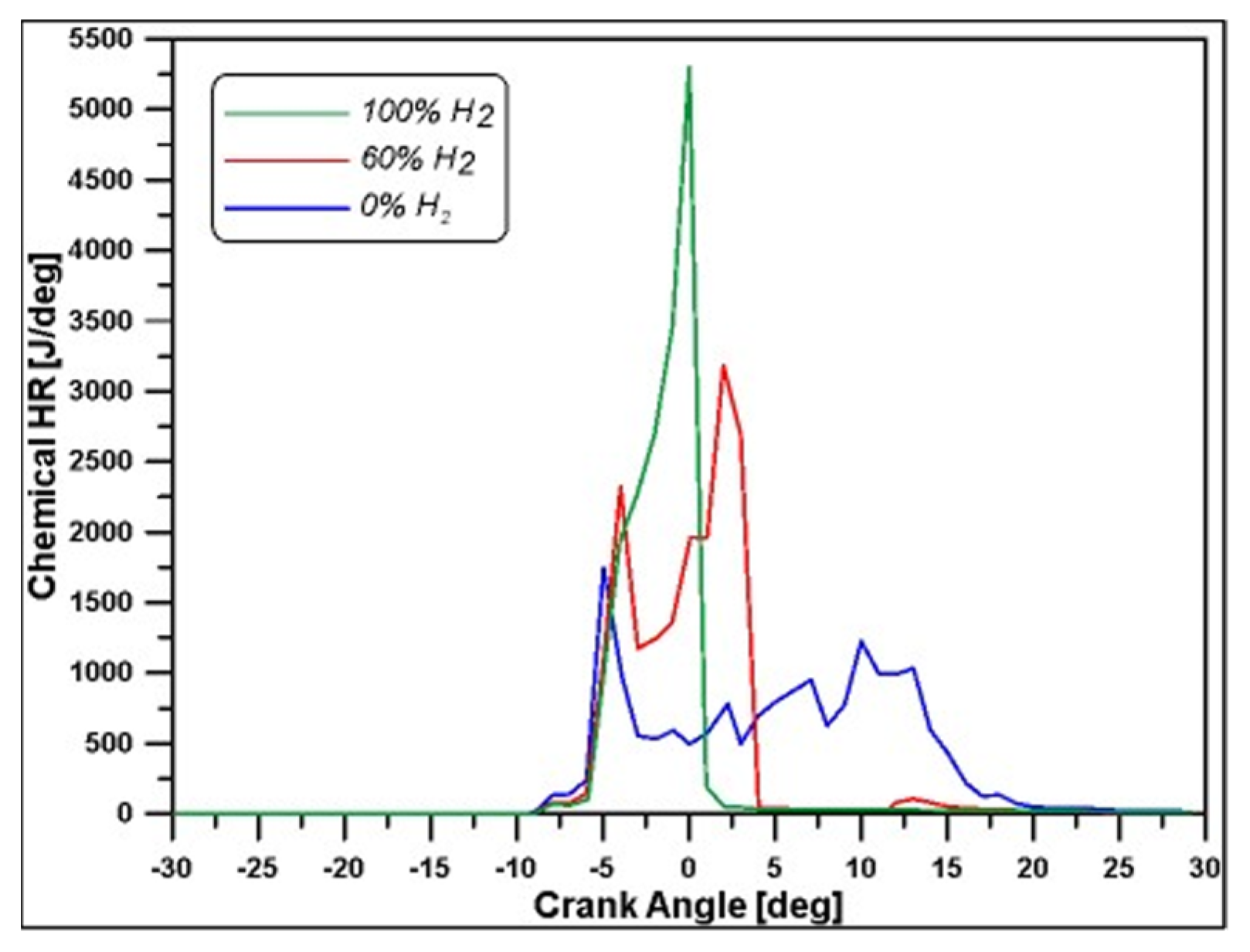
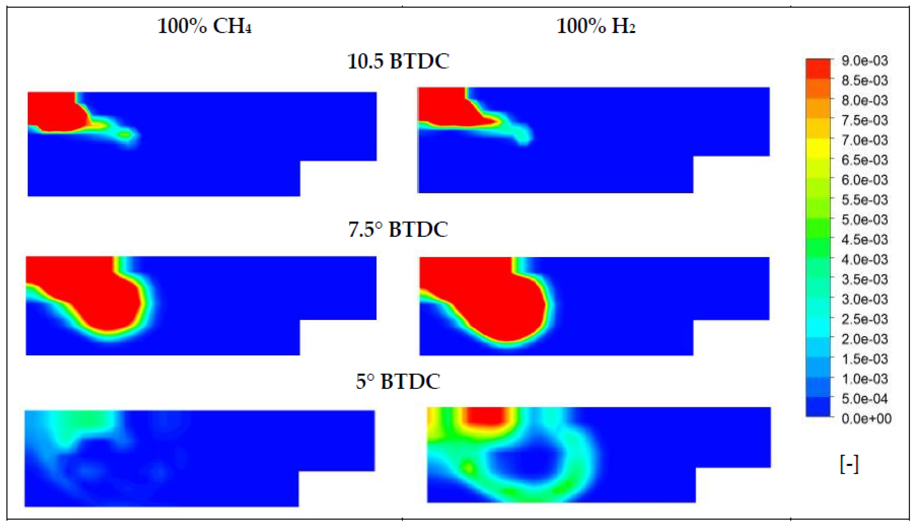
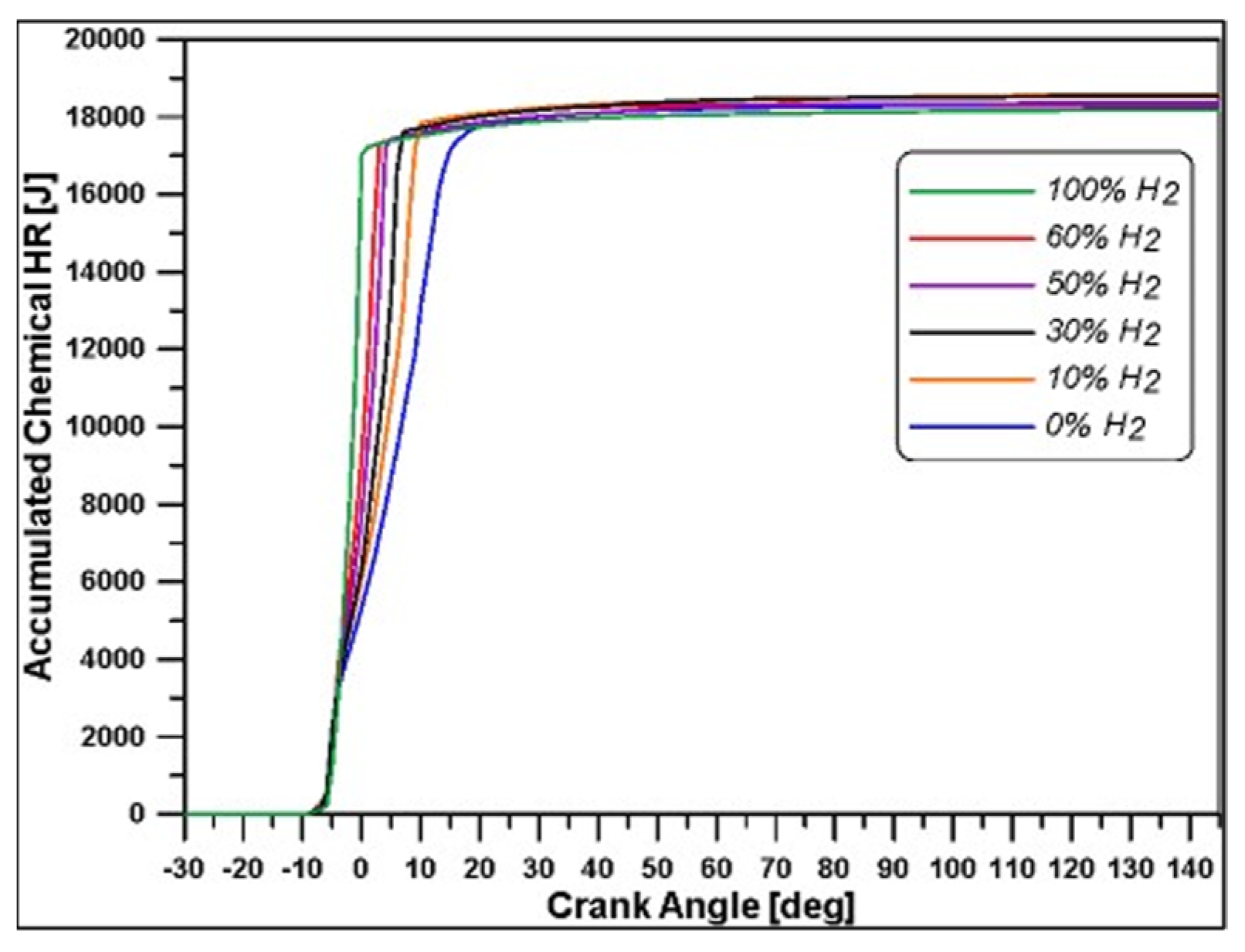
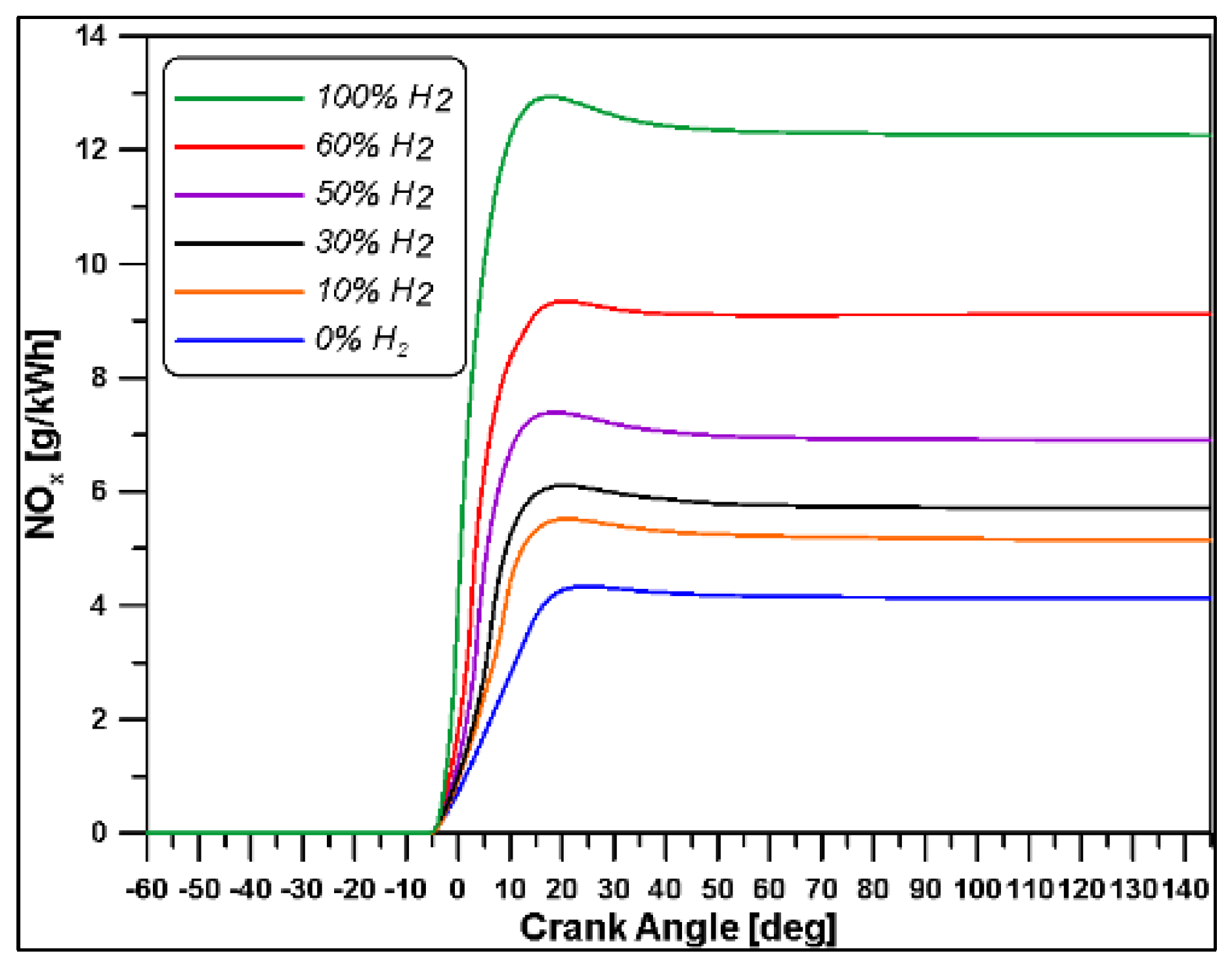
  • Once the necessary information has been obtained, the 3D calculation, performed with closed valves, allows for carrying out interesting results, such as the in-cylinder fuel vapor, temperature, and burning rate distributions, to better understand the mechanisms which govern the combustion phenomenon. As known, only a detailed CFD calculation can allow an investigation on the processes taking place inside the cylinder, especially in dual fuel operation where the adoption of two fuels with different physical and chemical properties makes the combustion process challenging to model, as extensively reported in scientific literature. Starting from the reference case with only natural gas as LRF, an increasing amount of hydrogen was introduced in different percentages, reducing the methane energy supply and investigating the effects of H2 substitution ratio on the engine parameters and emissions.
The 1D numerical model was calibrated starting from experimental data available in literature on the W20DF engine by Wärtsilä. For this purpose, the papers [24,46] were taken as reference. The engine geometric characteristics, the valve timing, the operating conditions (medium load), and fuels properties are reported in Table 2, Table 3, Table 4 and Table 5, respectively.
As said, the set of parameters listed in Table 4 refer to a medium load case. Moreover, the RP parameter reported in Table 5 indicates the premixed ratio, i.e., the energetic contribution of the primary fuel with respect to the total one, and it is defined as it follows:
R P = m p f L H V p f m p f L H V p f + m s f L H V s f   · 100
where mpf and msf are the masses of the primary and the secondary fuel, respectively. For this case, valid for the calibration of the model, the primary fuel is the LRF, and the secondary ones is HRF. The value of 0.5 of the global equivalence ratio (Table 5) takes into account both fuels.
It is important to highlight that with respect to the characteristics of the fuels reported in the cited papers [24,46], MK1 diesel and natural gas, the authors used n-dodecane and pure methane that do not feature the same exact properties. Therefore, these differences do not allow for careful reproduction of the experimental data, but the purpose of the authors was exclusively to get the main information on the combustion timing and development under specific operating conditions.

2.1. One-Dimensional Calculations

In order to obtain the pressure and temperature at the intake valve closure as initial conditions for 3D calculations, a single-cylinder 0D/1D model of the W20DF naval engine was implemented using commercial software. Its validation has been carried out against the trends of the release of heat as no in-cylinder pressure results were available from References [24,46]. In the model, the supercharging was considered by setting an intake pressure of 1.85 bar as reported in Table 4. The external temperature was adjusted to obtain the global equivalence ratio of 0.5. A back pressure of 2 bar was imposed on the exhaust duct. Since in References [24,46], no data are provided regarding the dimensions of ducts and junctions, these have been set based on the previous experience on a light-duty engine with a bore of 84 cm, reported in [45]. In particular, all the components have been scaled based on the ratio of the bores of the engine under investigation in this paper and the previous one: 200/84 = 2.38; therefore, an approximate multiplicative value of 2.5 was applied. Finally, the most appropriate orientation for the ducts was set.
Diesel pilot is directly injected in the cylinder while natural gas is injected in the intake manifold with a mass flow rate of 9.85 kg/h and with the following timing: start of methane injection at 330° BTDC and duration of 60°, i.e., up to 270° BTDC.
The Woschni correlation was used to model the heat transfer [47]. An axisymmetric swirl flow sub-model, which is a simple model that imposes a centered swirl within the cylinder, was used to model the turbulence. This flow model accounts for the bowl dimensions.
In regards to the combustion process, the Multi-Wiebe Fitting Tool was used. This allows for reading the combustion profiles taken from References [24,46] and for determining the correct parameters for the fitting of a non-predictive double zone Multi-Wiebe combustion sub-model such that it accurately recreates the combustion profile. This approach enables recreating more advanced and complex combustion profiles, taking into account various phenomena such as pre-injections, late injection burns, or the burning of different fuels as they happen in a dual fuel combustion [48,49]. In this paper, the experimental rates of heat release (ROHR) at medium load for different starts of injections reported in Reference [24] (Figure 1) were reproduced with the use of the Multi-Wiebe Fitting Tool.
Specifically, the Multi-Wiebe Fitting Tool allows for splitting the combustion into a number of multiple stages. The mass fraction burned x (Multi-Wiebe function) and the burning rate w can be expressed as follows:
x = f 1 · x 1 + f 2 · x 2 + + f N · x N
w = f 1 · w 1 + f 2 · w 2 + + f N · w N
where:
x i = 1 exp a i · θ θ 0 i θ i m i + 1 ,   i = 1 , , N
w i = a i · ( m i + 1 ) θ i · θ θ 0 i θ i m i + 1 · exp a i · θ θ 0 i θ i m i + 1 ,   i = 1 , , N
fi is the amplitude factor of the Wiebe function, which represents the contribution of each combustion stage to the rate of heat release. The mass fraction burned profile grows from zero to unity, and the distance between these two conditions is the duration of the combustion ∆θ. θ0 represents the crank angle at the start of combustion, while a and m are the efficiency parameter and the form factor, respectively. N is the number of stages of the Multi-Wiebe function, and for the simulations, the value was set to 3.
The trends of heat release, showed in Figure 1, have been imported into the 1D software, enabling the derivation of the results for the different values of the SOI; the in-cylinder pressures obtained by the 1D model are reported in Figure 2.
In the current work, among the medium-load cases, the one with a SOI = 15° BTDC (from now on, indicated as SOI15) was chosen as the focus of the investigations as it will also be analysed through 3D numerical simulations. Figure 3 shows a comparison between experimental ROHR and the numerical chemical heat release for the SOI15 case. Considering that, due to the high dimensions of the cylinder, the heat losses through walls seem to not be particularly significative, such a result can be deemed quite satisfactory in terms of the obtained IMEP, since its value is exactly 10 bar. For this reason, following the 1D outcomes, the pressure value of 1.66 bar (the consequence of the pressure drop in the upstream ducts of the engine) and the temperature value of 397 K (effect of charge heating) obtained at the intake valve closing (Table 3) have been set as initial values for all the following 3D numerical calculations.

2.2. CFD Calculations

The 3D numerical simulation tool employed in the present work is the well-known ANSYS Forte® software, used to compute the governing equations of the fluid as well as the mass balance, momentum balance, and turbulence effect. In this solver, the flow field equations are implemented jointly with the fuel injection model and chemical processes. In particular, the code is internally coupled with the CHEMKIN solver (Version 19.2). For the study of the combustion process, the simulations were performed with closed valves and, as said in the previous section, the initial conditions were obtained from 1D model simulations.

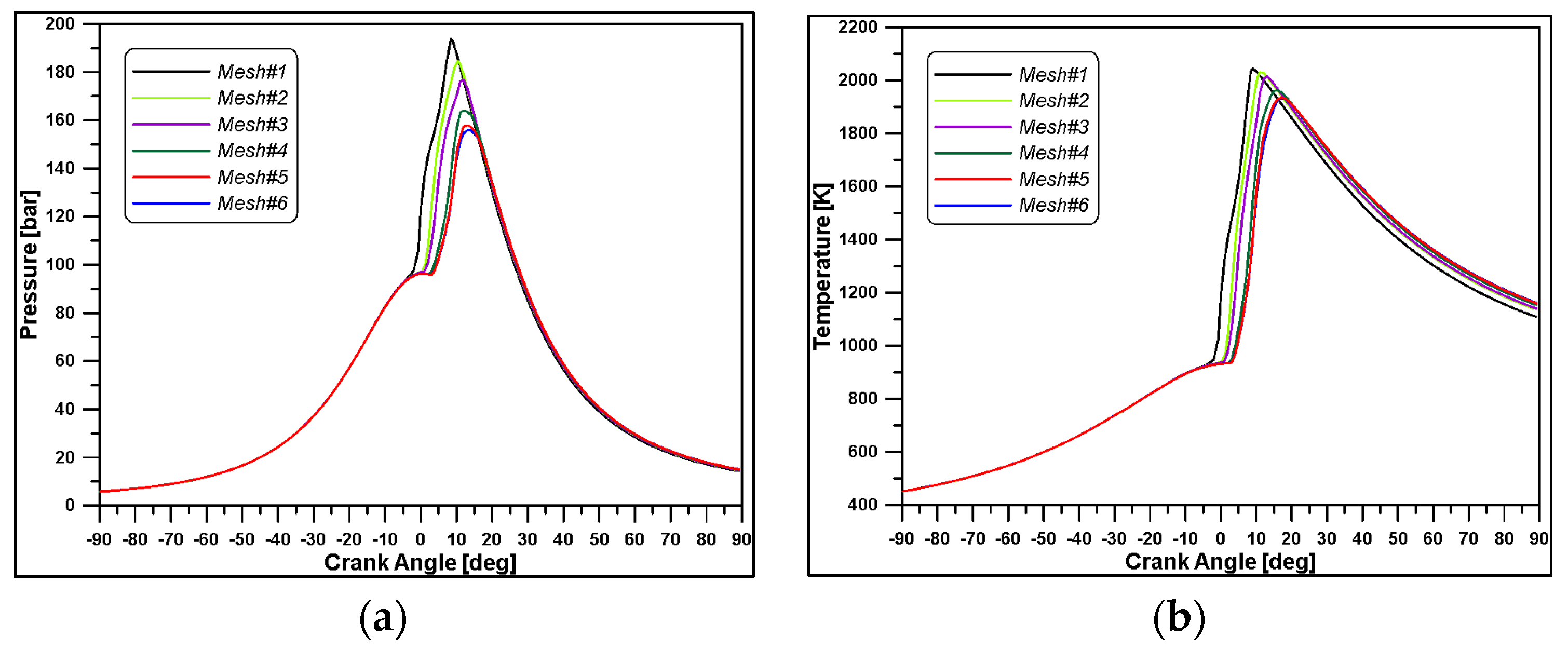
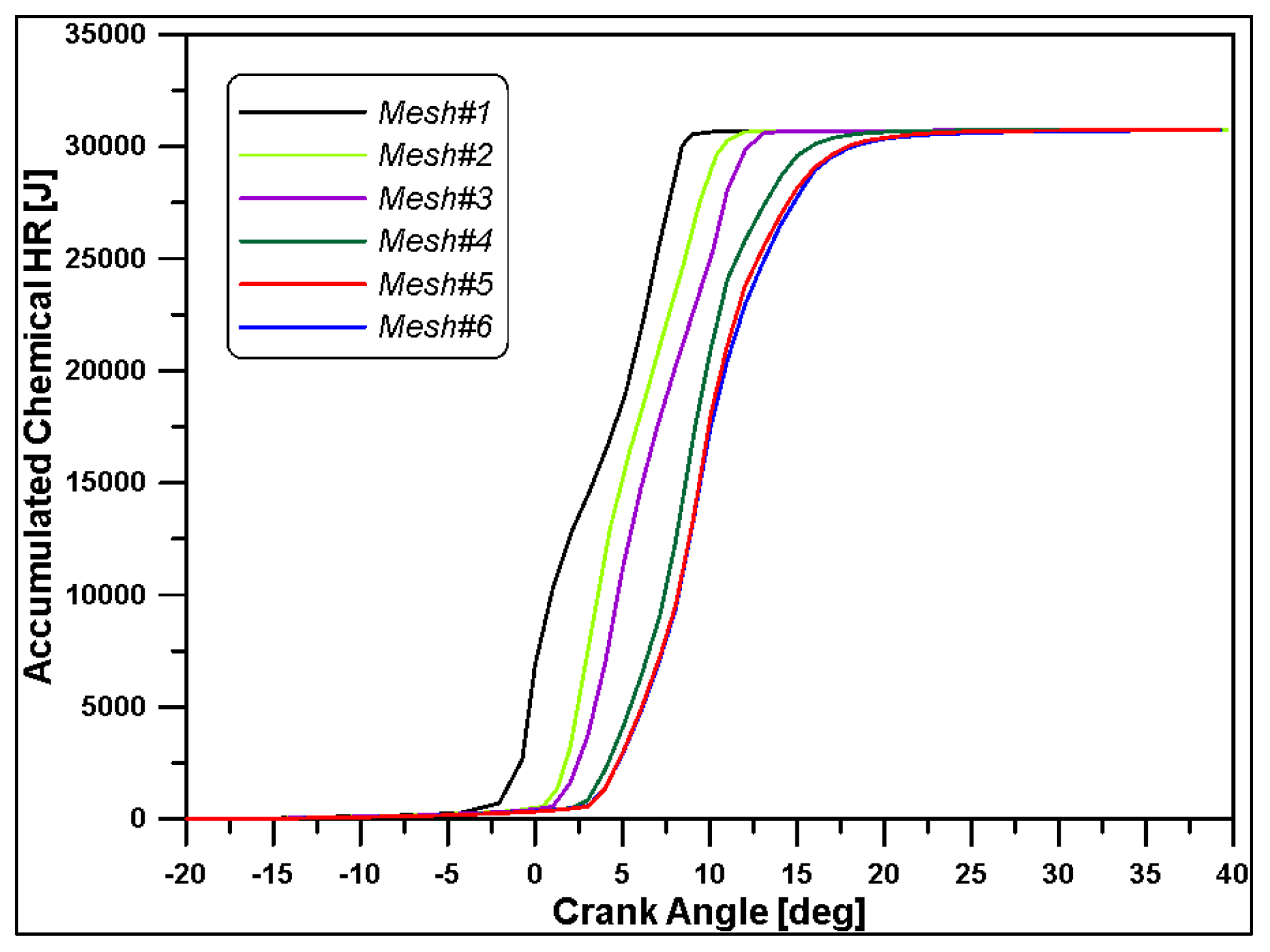
2.2.1. Mesh Sensitivity Analysis

The geometry of the cylinder was created based on the dimensions reported in Table 2. To reduce the computation times, only a sector of 40 degrees was considered since the diesel injector of the W20DF engine was equipped with nine holes and the domain was assumed as axisymmetric. As displayed in Figure 4a, a simplified bowl geometry was designed. A mesh sensitivity analysis was carried out, performing simulations on six grids ranging from 28 k to 210 k cells (see Table 6). Based on the results of Figure 5 and Figure 6, and considering the computational time, the mesh#5 (Figure 4b) was selected for the calculations.

2.2.2. Chemical Reactions Mechanism

As said before, the fuels used in the investigation differ, albeit slightly, from those of Reference [24]. Indeed, n-dodecane was used as a diesel surrogate, while for natural gas, a composition of 100% methane was considered as a surrogate. To simulate the combustion process, starting from the burning of diesel fuel, the kinetic scheme must also include a chain of reactions able to describe methane and hydrogen oxidations. In previous papers [38,39], the scheme proposed by Ra and Reitz [50] for n-dodecane was added to the well-established GRIMECH mechanism for the methane oxidation. The final mechanism consisted of 124 species and 660 reactions. Nevertheless, since auto-ignition chemistry is the key phase in dual fuel combustion development, to better account for the low temperature reactions of n-C12H26, in the present work, the authors made use of a different kinetic mechanism that is specifically extended to such a scope [44], as reported in [51]. Following the same methodology to obtain an extended model that included reaction mechanisms for diesel/methane/hydrogen blends, the GRIMECH 3.0 was again merged with the new reduced scheme via the ANSYS Chemkin-Pro® software (version 19.2), obtaining a final kinetic mechanism consisting of 151 species and 2570 reactions. A significant difference in terms of chemical heat release between the two kinetic mechanisms was achieved, as is observable in Figure 7, where the delayed ignition obtained with the old model justifies the necessity to introduce a new chemical reaction mechanism at low temperatures able to better reproduce the ignition process. The chemical mechanism is used in a kinetics–turbulence interaction model to deal with the combustion process, while the RANS (Reynolds Average Navier-Stokes) RNG k-ε model was used to simulate the turbulence. As known, the equations for the RANS approach are obtained by averaging the instantaneous balance equations that require a closure turbulence model to deal with the flow dynamics in combination with a turbulent combustion model to describe chemical species’ conversion and heat release. The renormalization group RNG k-ε model includes some additional terms for the dissipation rate development, improving the model accuracy.

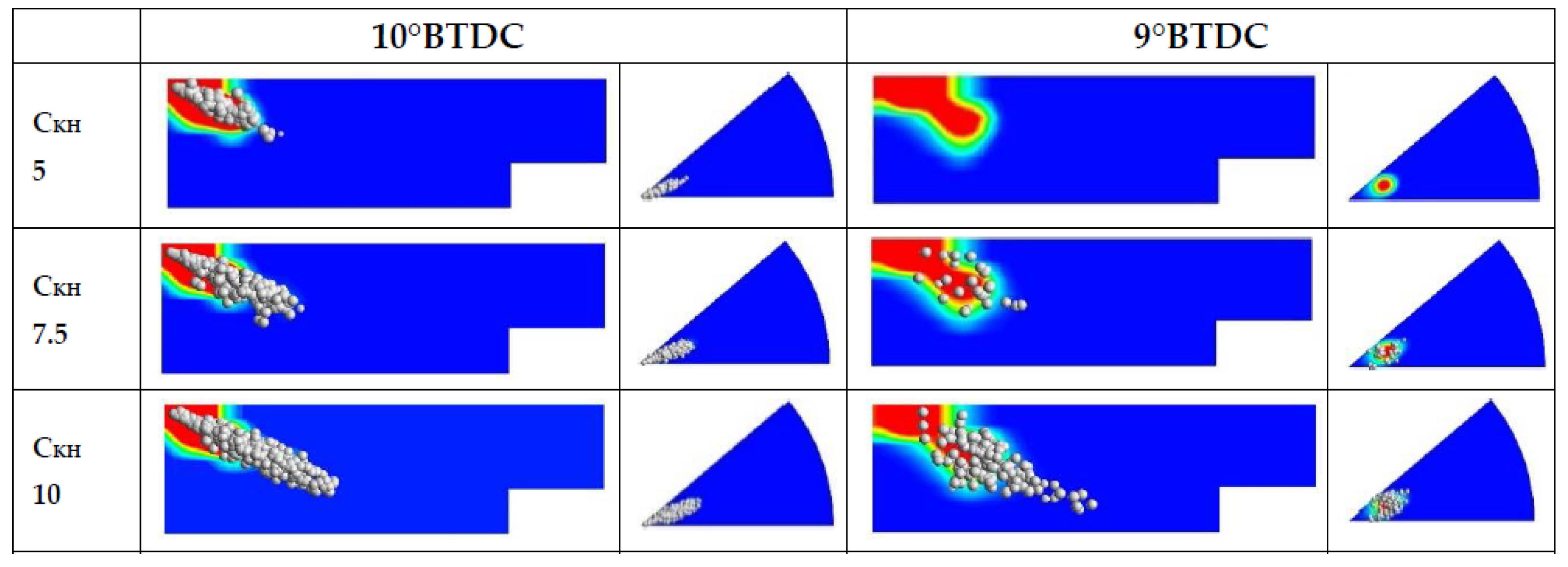
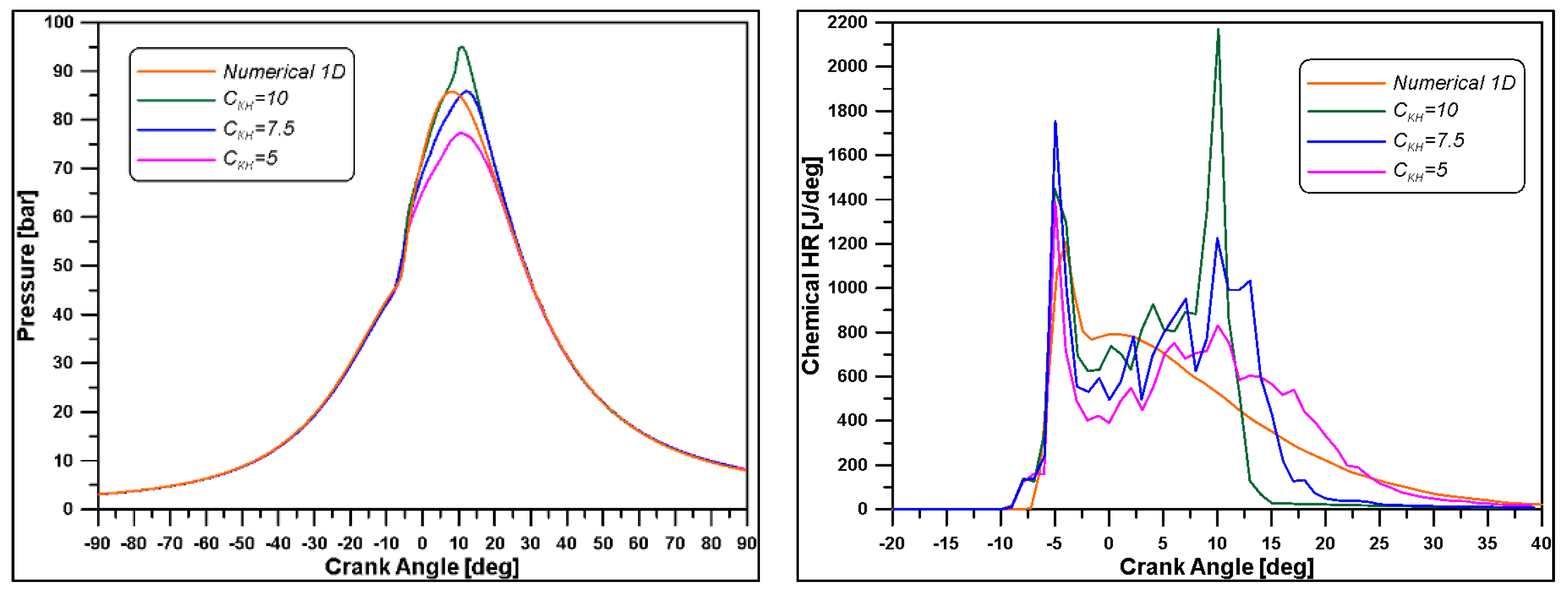
2.2.3. Atomization Model Analysis
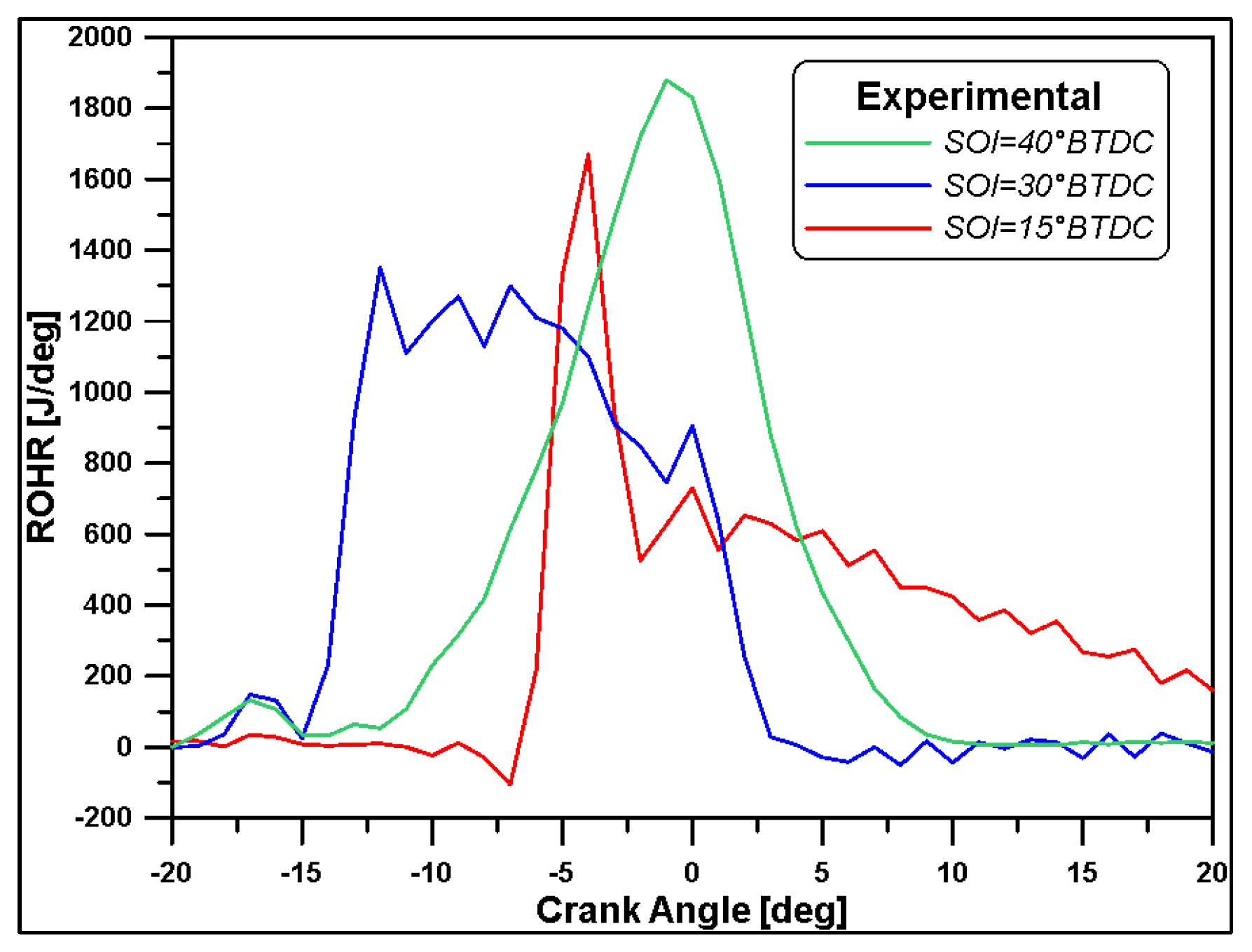
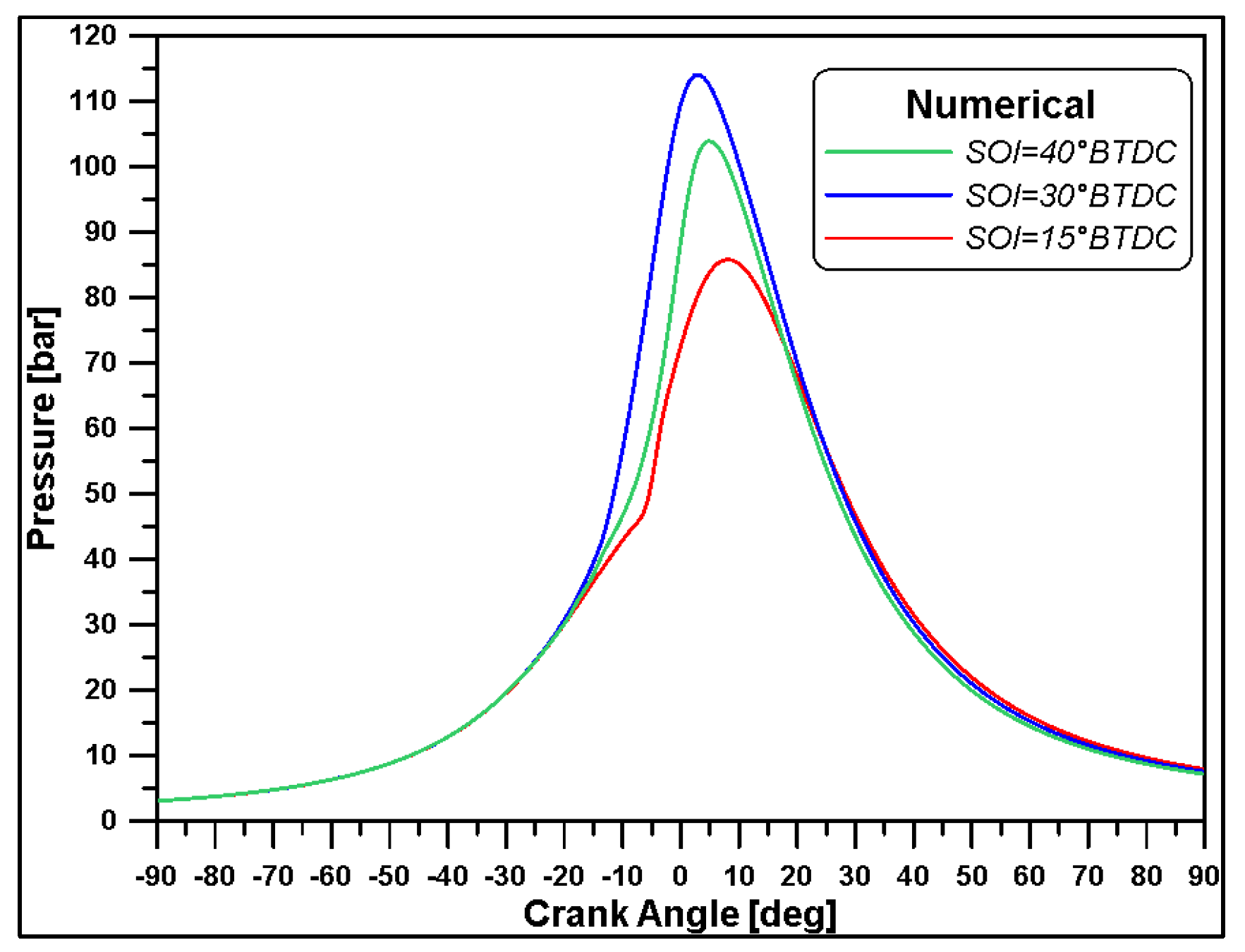
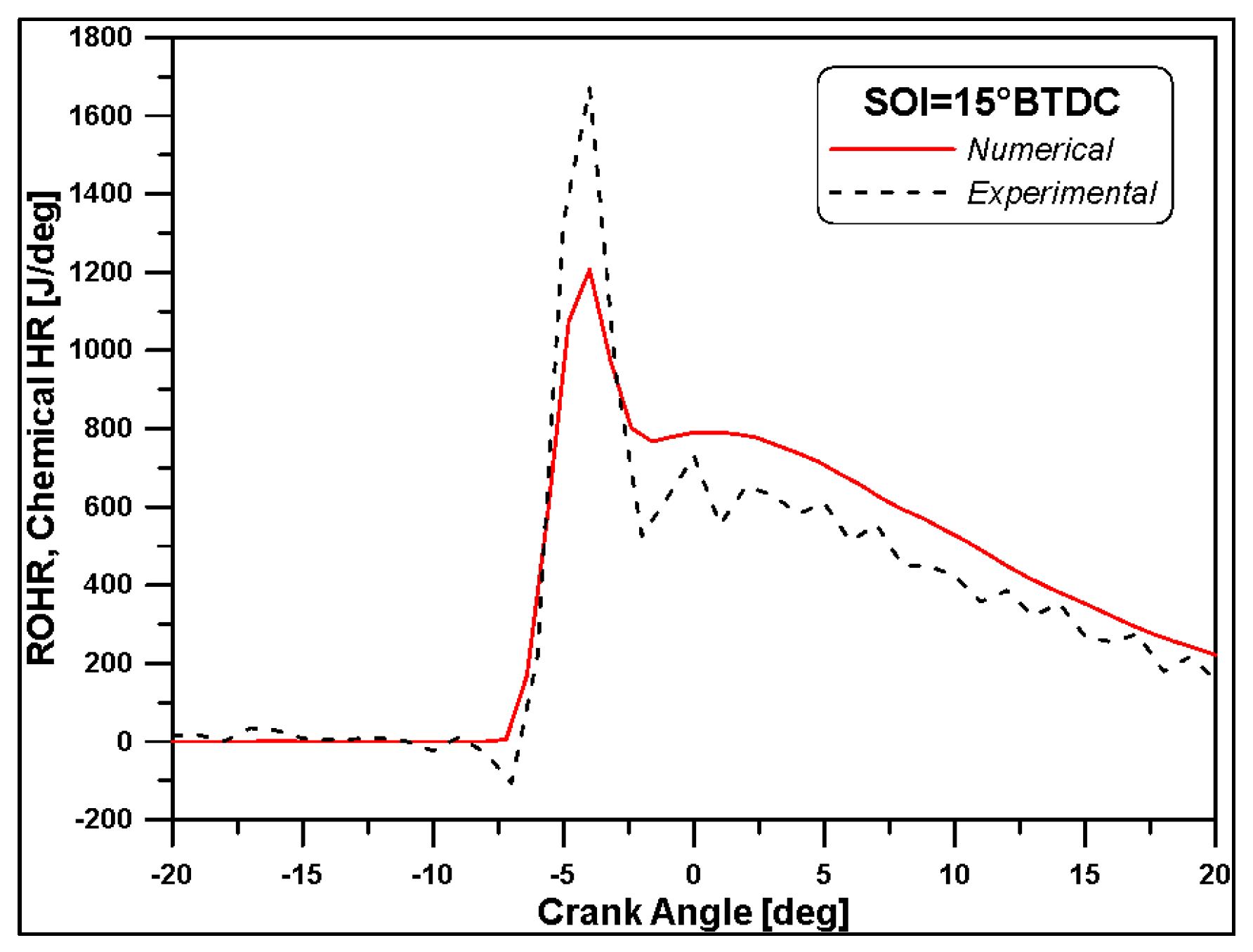
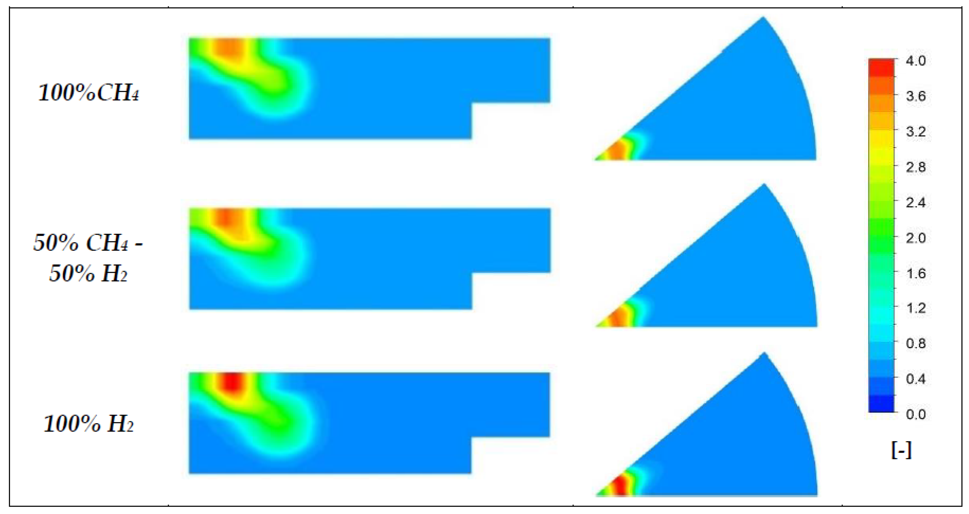
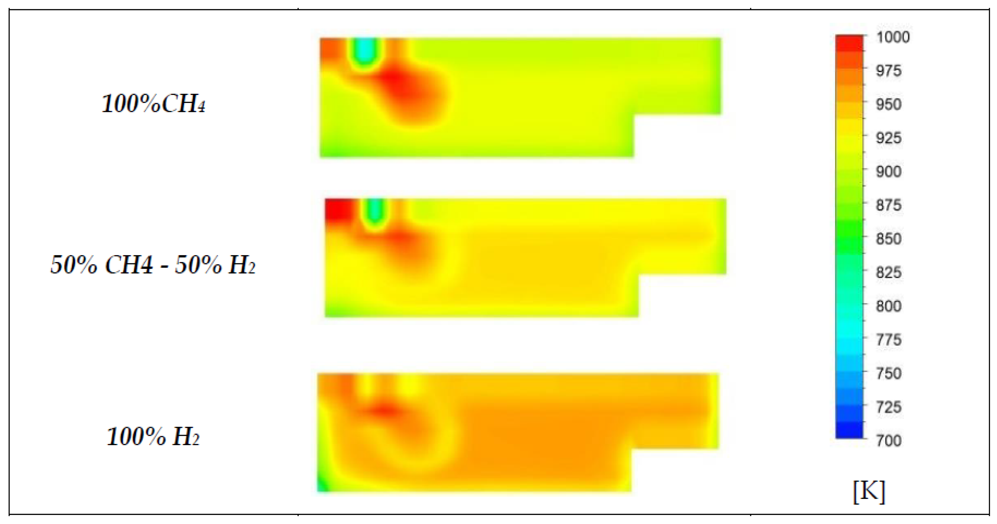
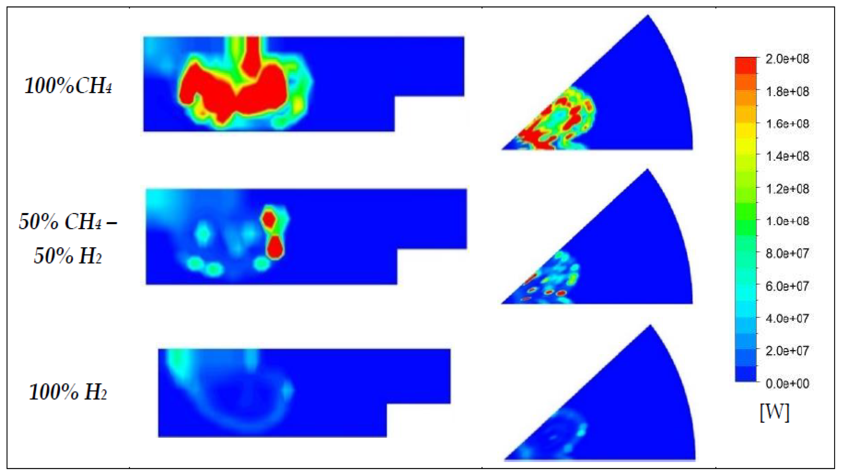
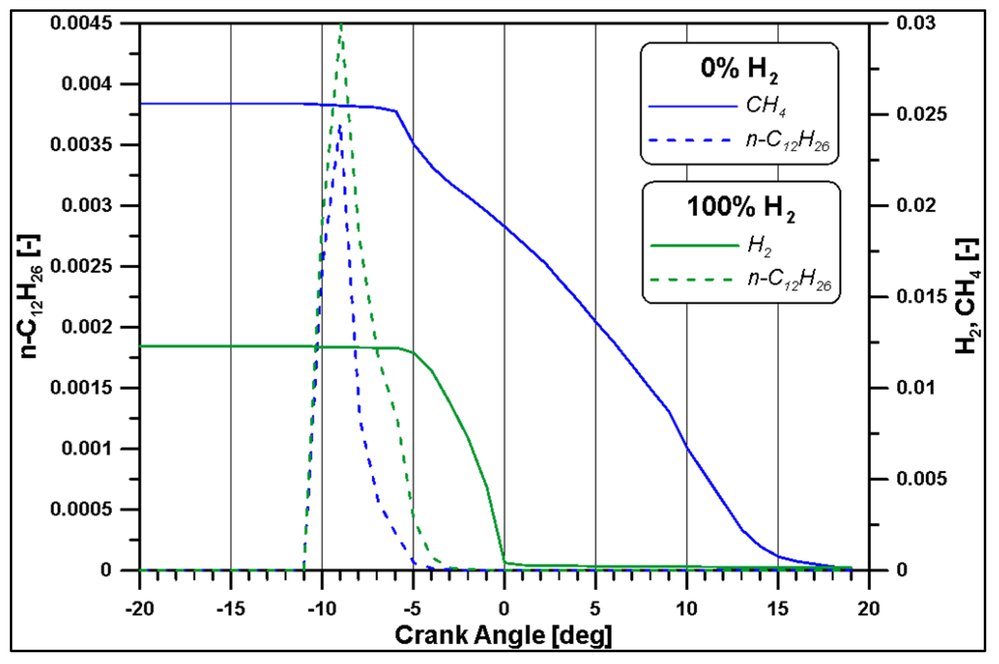
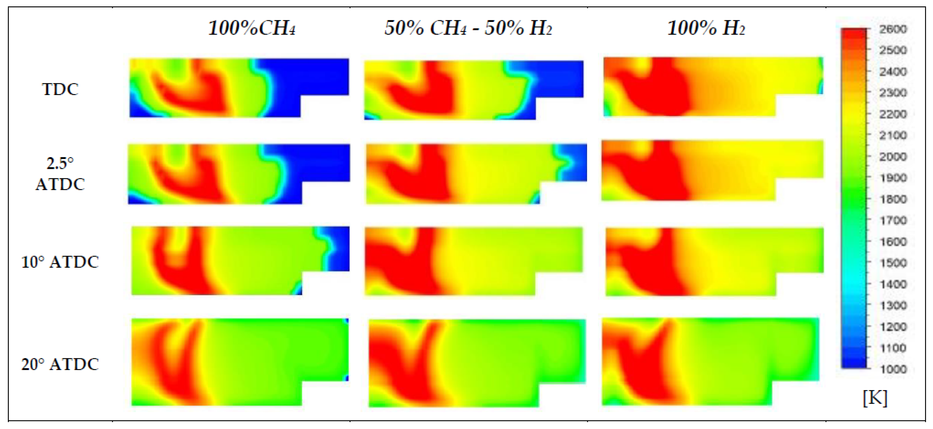
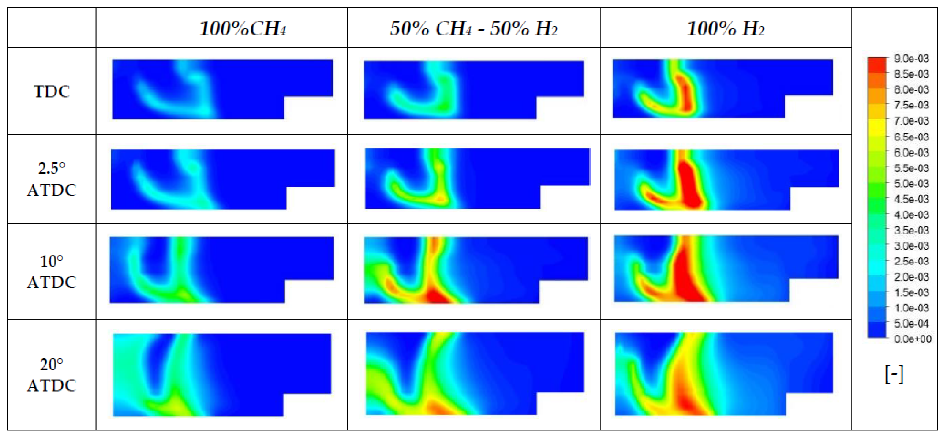
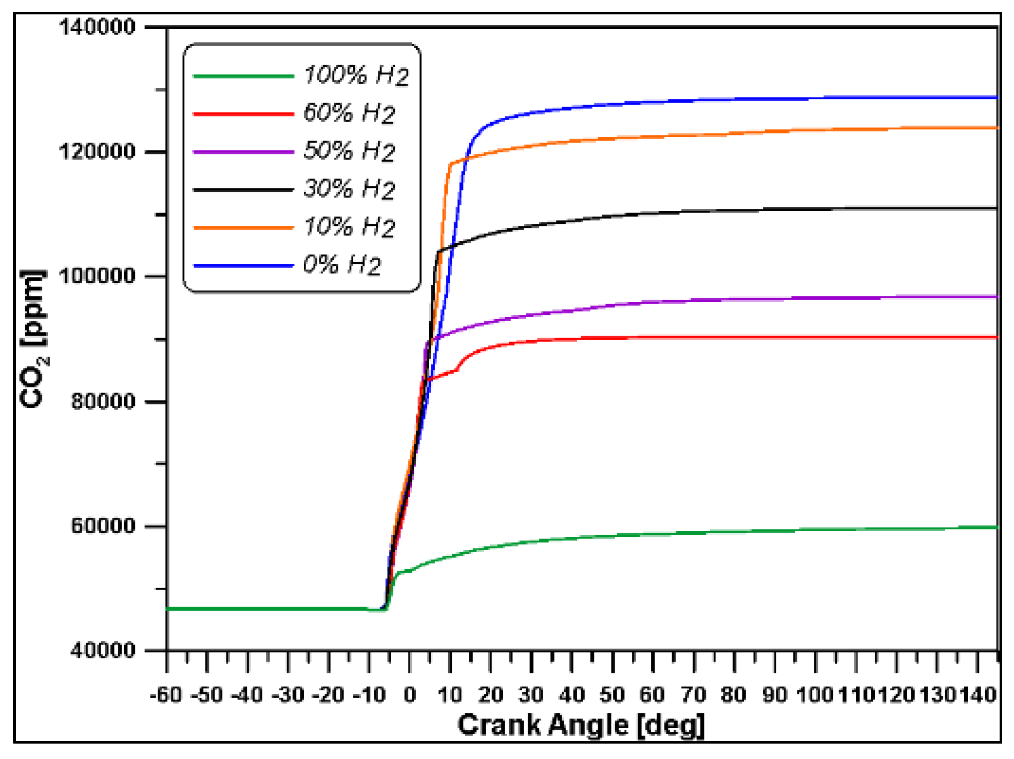
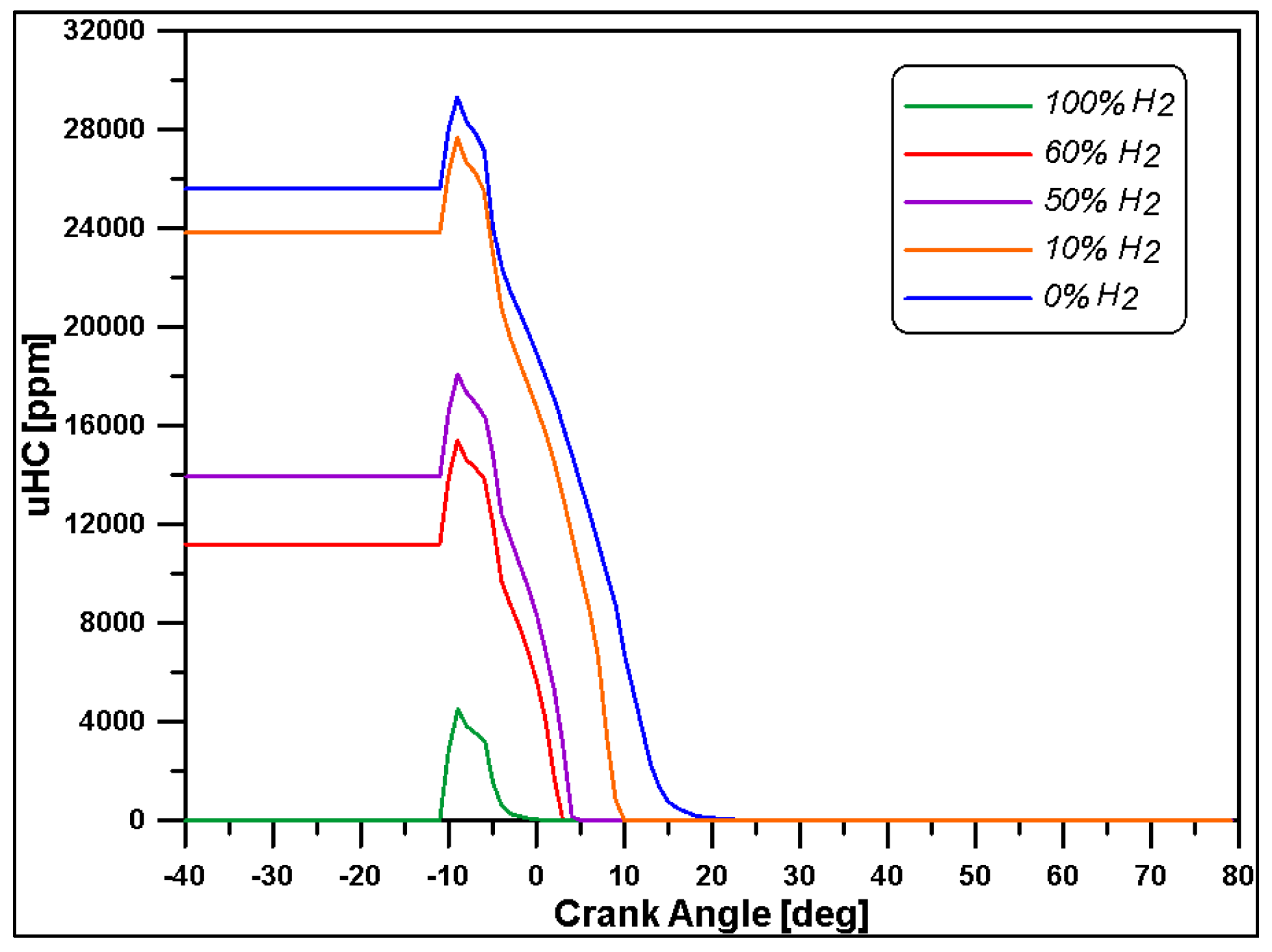
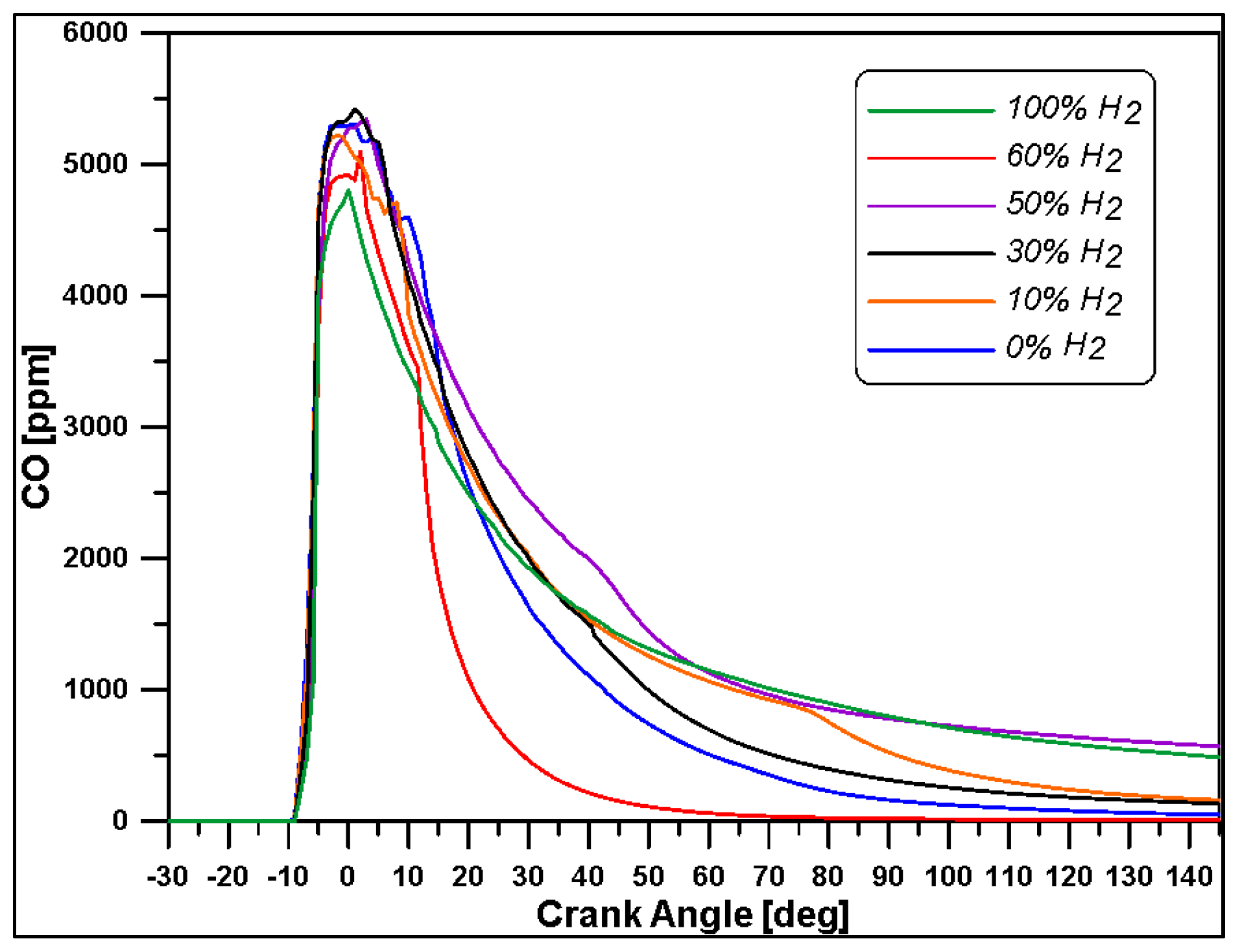
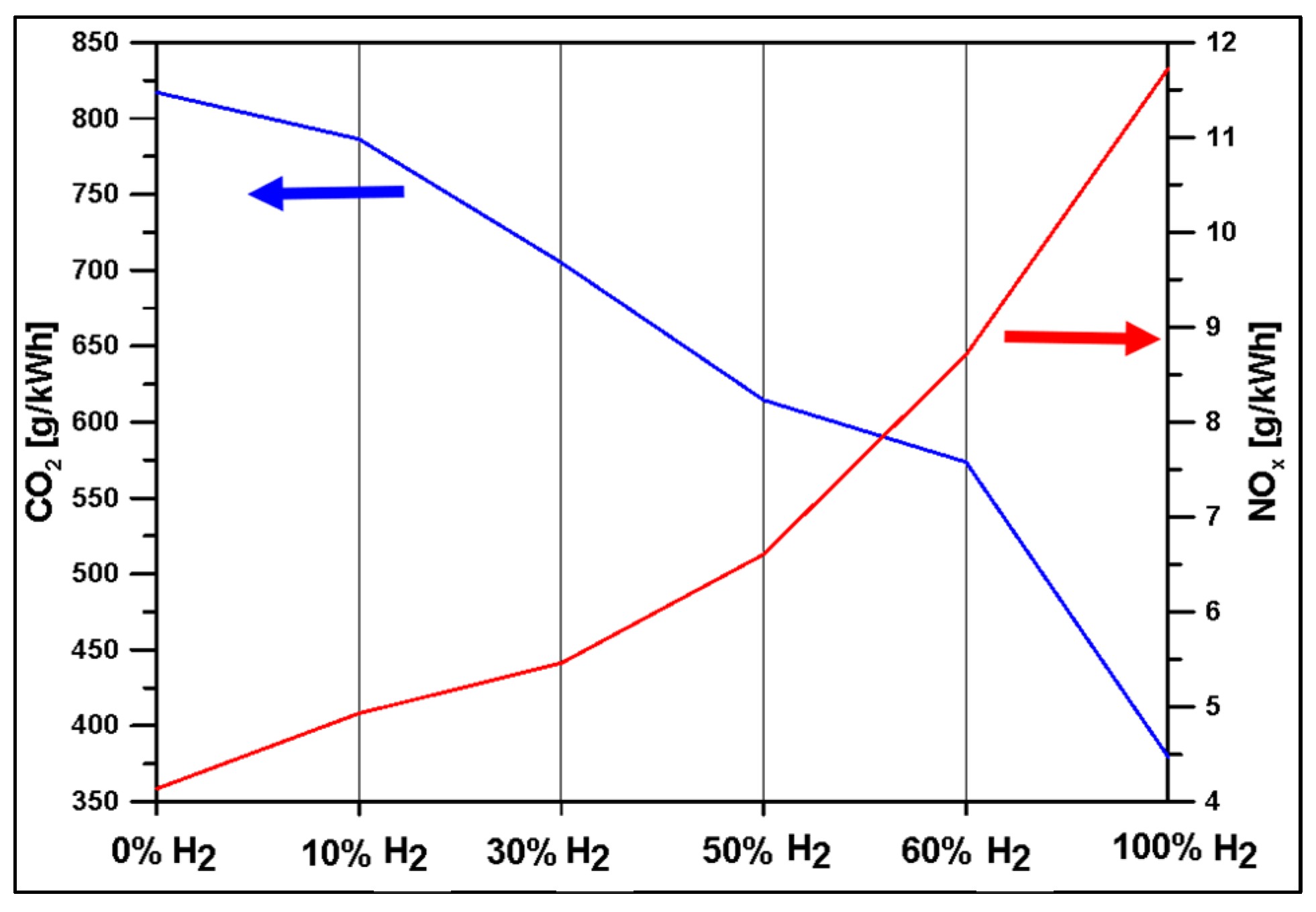
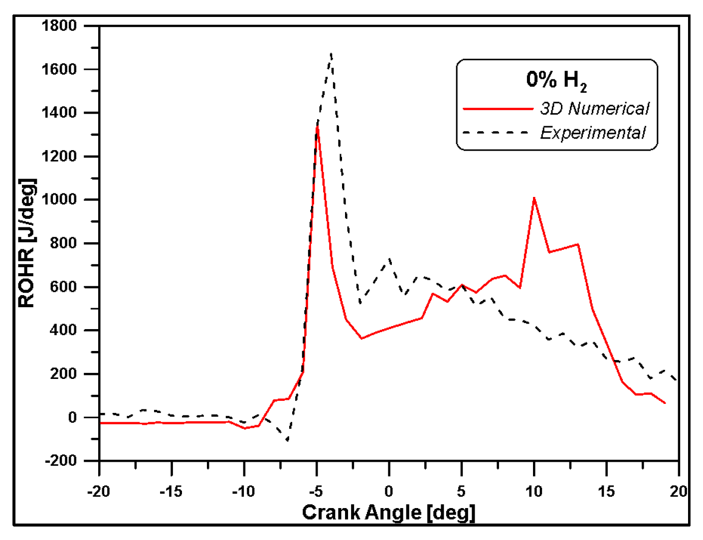
The diesel spray atomization and droplet breakup of spray is modelled by the well-known Kelvin–Helmholtz/Rayleigh–Taylor hybrid breakup model [49], as mentioned in the Introduction section. This is considered to be the most reliable model to describe the atomization process in DF combustion. It considers the interaction between aerodynamic breakup and instabilities due to droplet acceleration.
Among the several parameters present in the model, the results showed a sensitivity mainly to the KH breakup time scale, which is calculated as follows:
τ K H = 3.726   C K H r p Λ K H Ω K H
where CKH is the time constant of KH breakup, which can be calibrated according to the operating conditions. Only the KH breakup time constant effect was investigated via the CKH empirical constant, which is therefore modified, while other constants were kept at the default values. Indeed, this constant significantly affects the penetration evolutions of the sprays as reported by Reitz [52] and Brulatout [53]. As a matter of fact, by increasing the CKH constant value, the primary breakup time is increased, allowing a deeper tip penetration, and consequently modifying the vapor distribution as well. As shown in Figure 8, vapor distributions obtained on two cut planes in the cylinder for three different values of CKH ranging from 5 to 10 look clearly different. A small value (CKH = 5) excessively reduces the break time and at 9° BTDC, no droplets are present. The breakup timing affects the ignition delay, and consequently, the pressure peaks and the chemical heat releases as illustrated in Figure 9. The most suitable value to reproduce the results in terms of pressure and the start of combustion of the 1D model is CKH equal to 7.5. Indeed, as shown in Table 7, this value of CKH provides an IMEP of 10 bar. In addition, the pressure peak (86.68 bar) is the closest to the 0D case. This tuning combined with the updated chemical kinetic model described above allowed for adequately reproducing the start of the ignition.

3. Results

The performed calculations envisage a first case with only methane as the low-reacting fuel and subsequent five cases with methane–hydrogen blends with percentages of hydrogen supply varying from 10% to 100% (Table 8).
In Figure 10, the curves of the rate of heat release are plotted by comparing the numerical result with the experimental data [24] for the first test case with methane/air. As mentioned, although the used fuels do not coincide exactly, the numerical trend obtained is similar to the experimental one. Indeed, the timing of the combustion development was fairly reproduced. A two-stage shape of the curve was detected in the numerical simulation as well. The first peak, due to the pilot ignition, and especially the equal rise rate mean that the spray evolution and ignition were adequately reproduced. The second phase, due to methane oxidation, can be considered globally acceptable since the order of magnitude of the numerical ROHR is close to the experimental one for all the oxidation duration.
This encouraging outcome led to test new blends, gradually replacing methane with hydrogen and verifying the effect on combustion and emissions. The global equivalence ratio was kept almost constant at 0.5 for all the presented cases.
Despite the constant energy supply, in Figure 11, it is possible to observe that the substitution of part of the methane with hydrogen causes a progressive enhancement of pressure and temperature peaks and rise rates.
For a better presentation, in Figure 12, the chemical heat release is illustrated for only three blends. On the contrary, in Figure 13, the correspondent accumulated heat release is displayed for simulated cases. From both figures, it is possible to observe that the increase of the percentage of hydrogen leads to a decrease of the combustion duration, mainly due to the higher reactivity of this fuel including high burning velocity and LHV. In particular, hydrogen significantly affects the ignition phase and, hence, the consequent heat release.
Furthermore, it is necessary to indicate that in all cases, including the 100% CH4, the total energy of the fuels is released during combustion; in Figure 13, all cases reach 18 kJ at the end of the simulation, as reported in Table 8. This means that despite the load not being the full one, an efficient combustion is still achievable for different load levels in this type of engine, explaining the success of dual fuel technology in the maritime field.
To better understand the combustion development of the HRF and LRF fuels, the images in Figure 14 show the dispersion of diesel vapor in the cylinder for the two extreme test cases (100% CH4 and 100% H2): in the case with air/hydrogen mixture, the vapor amount occupies a greater volume with higher penetration. This can be explained by the lower density and higher diffusivity of hydrogen that allow a higher diffusion of diesel vapor as well. However, this feature can lead to slightly retarded ignition of the mixture but is later compensated by the higher velocity of H2 oxidation [54,55], explaining the trends observed in Figure 12.
The equivalence ratio and temperature distributions at 7.5 BTDC, i.e., before mixture ignition, in Figure 15 and Figure 16 confirm the different behavior of diesel vapor by varying the CH4/H2 ratio and the different ignition timing in the two cases. In particular, Figure 16 makes evident the high thermal diffusivity of hydrogen. At 7.5° BTDC, the combustion has just started, but a higher level of temperature has already involved the bulk mass consisting of a perfectly premixed combination of air and hydrogen.
In Figure 17, the chemical heat reaction rate distribution at 5° BTDC (at this crank angle, hydrogen starts to burn) is represented for three blends: the diesel reactivity is clearly higher in the case of a mixture with pure methane (100% CH4). Such outcomes are confirmed by Figure 18: the trends of the fuels demonstrate a faster diesel consumption in this last case, as well as a slightly delayed ignition of the hydrogen in respect to methane. Once the oxidation of the hydrogen-based mixture begins, combustion develops rapidly, as already discussed for Figure 12 and Figure 13. These considerations are in accordance with those already present in literature, for instance as demonstrated in References [56,57], meaning that the model is capable of describing the phenomena within the cylinder.
As already observed in Figure 11b, the increasing percentage of H2 in the mixture leads not only to higher peaks of temperature, but also to mean temperature levels of the mass involved in the combustion [55]. Temperature contours reported in Figure 19 show that in the region where diesel fuel has been injected, wider zones at higher temperature are achieved. Also, the higher reactivity of hydrogen is evidenced at 2.5 and 10° ATDC because it is possible to observe a sort of flame front that divides the high temperature region that is gradually limited with the decreasing presence of H2, from the unburned zone. Furthermore, the NO species distributions reported in Figure 20 for the same crank angle degrees and cases of Figure 19 are evidence of the strong link between temperature and nitrogen oxides. Higher concentrations of NO can be found in correspondence of temperature peaks. Figure 21 and Figure 22 explain why: although hydrogen leads to important benefits regarding CO2 emissions, its usage is usually limited in terms of percentage due to the increase of NOx emissions, as reported in several papers [58,59,60,61,62]. In fact, as hydrogen is added or substituted, temperature and pressure increase due to its high speed of burning and a sufficient presence of oxygen being able to produce more NOx [29,56]. As a matter of fact, if an EGR system is not adopted, the emissions of NOx increase with hydrogen; but, on the other hand, since hydrogen is a carbon-free fuel whose combustion generates only water, a significant reduction of CO2 emissions can be obtained. In fact, the CO2 emissions for the case of 100% H2 is due almost exclusively to the injected pilot fuel (n-C12H26).
Finally, the attenuation of CO and UHC pollutants in Figure 23 and Figure 24 refers to the gaseous state of hydrogen and to the non-existence of carbon in the hydrogen structure [63,64]. Although regulations relating to marine transportation do not take these emissions into account, this result confirms the advantages of hydrogen fuel.

4. Conclusions

In this work, a numerical study of a combustion process in a dual fuel marine engine was presented. The engine is fuelled with natural gas through the intake port and with diesel oil by a direct high-pressure injector. The combustion model was tuned with reference to the experimental dataset from scientific literature. This included various operating conditions at a rotational speed of 1000 rpm, and different engine loads and timings of direct injection. For 3D simulation, a specific operating condition at medium load was chosen. The CFD calculations were performed by using the ANSYS Forte® software (version 19.2). Early on, a premixed methane mixture was considered and then was gradually replaced with hydrogen: five types of mixtures were tested by varying the energy contribution of the hydrogen (from 10% to 100%), evaluating the main characteristic variables that describe the combustion development and the polluting emissions.
To better reproduce the ignition timing, a new kinetic mechanism from literature, which considers low-temperature reactions, was used and coupled into the CFD framework code. This reduced scheme was merged with GRIMECH 3.0 via ANSYS Chemkin-Pro® software to predict diesel/methane/hydrogen oxidation. This new kinetics scheme allowed for adequately reproducing the ignition timing for the various mixtures used. The resulting combustion behavior was analysed in detail with respect to methane/hydrogen ratio. In particular, the ignition timing of mixtures varies according to the hydrogen content and the density of the mixture, acting on the evolution of the vapor of the HRF fuel which triggers the ignition.
The observation of distributions inside the cylinder of diesel vapor and its equivalence ratio allows to understand the trend of the heat release rate that rises from diesel auto-ignition in the most reactive mixtures and propagates to the surrounding areas. It is evident that the diesel vapor placement influences the subsequent oxidation of the mixture and, further, in the cases with a higher hydrogen amount, the thermal diffusivity increases, also noted by more homogeneous temperature distribution during the low-temperature combustion phase. These conditions slow down the combustion of the area occupied by the diesel fuel and, consequently, the ignition start of the hydrogen-based mixture.
Finally, based on the results obtained, light was shed on the increase of the nitrogen oxides amount if high hydrogen content is present in the premixed charge. The benefits in terms of CO2 and unburned hydrocarbons were also evaluated.
As a summary, the final emissions of NOx and CO2 are reported in the trade-off diagram in Figure 25 as a function of H2 percentage. The 54% decrease in the amount of CO2 allows for the current stringent requirements to be satisfied in terms of GHG at the expense of the increase in NOx. The unacceptable values referring to recent regulations [5] and the limit are better identified in Figure 26 for the engine and the operating condition under investigation.
A certain degree of uncertainty should be accounted for because no experimental data are available in the operative conditions adopted and the model could overestimate such values. However, the trends seem in accordance with the outcomes from literature [31], demonstrating that NOx can increase by 76%, going from 0 to 100% hydrogen content in the mixture.
It should be highlighted that in the calculations, neither EGR nor exhaust abatement systems are taken into account that are necessary to contain such pollutants in the exhaust. Nevertheless, the existence of the opposite trends of CO2 and NOx implies a rational choice of the H2 percentage in the mixture that can be based on several factors such as: operating conditions, performance, efficiency, and emissions. Also, it has not been determined that a fixed percentage of hydrogen in the premixed charge can be kept constant by varying the load level.
In conclusion, the presented approach demonstrated to be quite a reliable tool to predict the performance of an engine working under dual fuel mode with hydrogen-based blends, while its consistency remains to be verified under different operating conditions in terms of diesel injection timing and pressure, which play a major role in determining the combustion phase. Furthermore, as the next development of that approach, an appropriate flame propagation description will be embedded in the model, with the aim of refining the prediction of heat release rate.

Author Contributions

Conceptualization, M.C.C.; methodology, M.C.C. and M.P.; calculations, M.P.; validation, M.C.C., R.D.R., and M.P.; investigation, M.C.C. and M.P.; data curation, R.D.R. and M.P; original draft preparation, M.C.C., R.D.R., and M.P; supervision, M.C.C. All authors have read and agreed to the published version of the manuscript.

Funding

This research received no external funding.

Acknowledgments

The CFD computations are licensed by ANSYS-FORTE.

Conflicts of Interest

The authors declare no conflict of interest.

Abbreviations

ATDCAfter Top Dead Center
BMEPBrake Mean Effective Pressure
BTDCBefore Top Dead Center
CADCrank Angle Degree
CFDComputational Fluid Dynamics
DFDual Fuel
DPFDiesel Particulate Filters
ECAEmission Control Area
EGRExhaust Gas Recirculation
EREquivalence Ratio
EVCExhaust Valve Closing
EVOExhaust Valve Opening
GHGGreenhouse Gas
GWPGlobal Warming Potential
HFOHeavy Fuel Oils
HRFHigh Reactivity Fuels
IMEPIndicated Mean Effective Pressure
IMOInternational Maritime Organization
IVCIntake Valve Closing
IVOIntake Valve Opening
KHRTKelvin–Helmholtz/Rayleigh–Taylor
LHVLower Heating Value
LNGLiquefied Natural Gas
LRFLow Reactivity Fuels
NGNatural Gas
NOxNitrogen Oxide
PMParticulate Metter
RANSReynolds Average Navier-Stokes
ROHRRate of Heat Release
RPPremixed Ratio
SCRSelective Catalytic Reduction
SOxSulfur Oxide
SOCStart of Combustion
SOIStart of Injection
TDCTop Dead Center
UHCUnburned Hydrocarbon

References

  1. Viana, M.; Hammingh, P.; Colette, A.; Querol, X.; Degraeuwe, B.; de Vlieger, I.; van Aardenne, J. Impact of maritime transport emissions on coastal air quality in Europe. Atmos. Environ. 2014, 90, 96–105. [Google Scholar] [CrossRef]
  2. Eyring, V.; Isaksen, I.S.A.; Berntsen, T.; Collins, W.J.; Corbett, J.J.; Endresen, O.; Grainger, R.G.; Moldanova, J.; Schlager, H.; Stevenson, D.S. Transport impacts on atmosphere and climate: Shipping. Atmos. Environ. 2010, 44, 4735–4771. [Google Scholar] [CrossRef]
  3. Li, L.; Pan, Y.; Gao, S.; Yang, W. An innovative model to design extreme emission control areas (ECAs) by considering ship’s evasion strategy. Ocean Coast Manag. 2022, 227, 106289. [Google Scholar] [CrossRef]
  4. Chang, Y.-T.; Park, H.; Lee, S.; Kim, E. Have Emission Control Areas (ECAs) harmed port efficiency in Europe? Transp. Res. Part D Transp. Environ. 2018, 58, 39–53. [Google Scholar] [CrossRef]
  5. Amendments to the Annex of the Protocol of 1997 to Amend the International Convention for the Prevention of Pollution from Ships, 1973-176(58), as Modified by the Protocol of 1978 Relating Thereto (Revised MARPOL Annex VI). 2011. Available online: https://www.lemoci.com/media/omi-2008-marpol-annexe-6.pdf (accessed on 27 April 2023).
  6. Zhu, Y.; Zhou, W.; Xia, C.; Hou, Q. Application and Development of Selective Catalytic Reduction Technology for Marine Low-Speed Diesel Engine: Trade-Off among High Sulfur Fuel, High Thermal Efficiency, and Low Pollution Emission. Atmosphere 2022, 13, 731. [Google Scholar] [CrossRef]
  7. Li, X.; Li, K.; Yang, H.; Wang, Z.; Liu, Y.; Shen, T.; Tu, S.; Lou, D. Experimental evaluation of DPF performance loaded over Pt and sulfur-resisting material for marine diesel engines. PLoS ONE 2022, 17, e0272441. [Google Scholar] [CrossRef]
  8. Winnes, H.; Fridell, E.; Moldanová, J. Effects of Marine Exhaust Gas Scrubbers on Gas and Particle Emissions. J. Mar. Sci. Eng. 2020, 8, 299. [Google Scholar] [CrossRef]
  9. Tadros, M.; Ventura, M.; Soares, C.G. Optimization of the Performance of Marine Diesel Engines to Minimize the Formation of SOx Emissions. J. Mar. Sci. Appl. 2020, 19, 473–484. [Google Scholar] [CrossRef]
  10. Sun, X.; Ning, J.; Liang, X.; Jing, G.; Chen, Y.; Chen, G. Effect of direct water injection on combustion and emissions characteristics of marine diesel engines. Fuel 2022, 309, 122213. [Google Scholar] [CrossRef]
  11. Zhang, E.; Liang, X.; Zhang, F.; Yang, P.; Cao, X.; Wang, X.; Yu, H. Evaluation of Exhaust Gas Recirculation and Fuel Injection Strategies for Emission Performance in Marine Two-Stroke Engine. Energy Procedia 2019, 158, 4523–4528. [Google Scholar] [CrossRef]
  12. Abdelhameed, E.; Tashima, H. EGR and Emulsified Fuel Combination Effects on the Combustion, Performance, and NOx Emissions in Marine Diesel Engines. Energies 2022, 16, 336. [Google Scholar] [CrossRef]
  13. Al-Enazi, A.; Okonkwo, E.C.; Bicer, Y.; Al-Ansari, T. A review of cleaner alternative fuels for maritime transportation. Energy Rep. 2021, 7, 1962–1985. [Google Scholar] [CrossRef]
  14. Tan, E.C.D.; Hawkins, T.R.; Lee, U.; Tao, L.; Meyer, P.A.; Wang, M.; Thompson, T. Biofuel Options for Marine Applications: Technoeconomic and Life-Cycle Analyses. Environ. Sci. Technol. 2021, 55, 7561–7570. [Google Scholar] [CrossRef] [PubMed]
  15. Thomson, H.; Corbett, J.J.; Winebrake, J.J. Natural gas as a marine fuel. Energy Policy 2015, 87, 153–167. [Google Scholar] [CrossRef]
  16. Zardoya, A.R.; Lucena, I.L.; Bengoetxea, I.O.; Orosa, J.A. Research on the new combustion chamber design to operate with low methane number fuels in an internal combustion engine with pre-chamber. Energy 2023, 275, 127458. [Google Scholar] [CrossRef]
  17. Oloruntobi, O.; Chuah, L.F.; Mokhtar, K.; Gohari, A.; Onigbara, V.; Chung, J.X.; Mubashir, M.; Asif, S.; Show, P.L.; Han, N. Assessing methanol potential as a cleaner marine fuel: An analysis of its implications on emissions and regulation compliance. Clean. Eng. Technol. 2023, 14, 100639. [Google Scholar] [CrossRef]
  18. Abadie, L.M.; Goicoechea, N. Powering newly constructed vessels to comply with ECA regulations under fuel market prices uncertainty: Diesel or dual fuel engine? Transp. Res. D Transp. Environ. 2019, 67, 433–448. [Google Scholar] [CrossRef]
  19. Sinha, R.P.; Nik, W.M.N.W. Investigation of propulsion system for large LNG ships. IOP Conf. Ser. Mater. Sci. Eng. 2012, 36, 012004. [Google Scholar] [CrossRef]
  20. Yu, H.; Wang, W.; Sheng, D.; Li, H.; Duan, S. Performance of combustion process on marine low speed two-stroke dual fuel engine at different fuel conditions: Full diesel/diesel ignited natural gas. Fuel 2022, 310, 122370. [Google Scholar] [CrossRef]
  21. Rochussen, J.; Jaeger, N.S.B.; Penner, H.; Khan, A.; Kirchen, P. Development and demonstration of strategies for GHG and methane slip reduction from dual-fuel natural gas coastal vessels. Fuel 2023, 349, 128433. [Google Scholar] [CrossRef]
  22. Qu, J.; Feng, Y.; Xu, G.; Zhang, M.; Zhu, Y.; Zhou, S. Design and thermodynamics analysis of marine dual fuel low speed engine with methane reforming integrated high pressure exhaust gas recirculation system. Fuel 2022, 319, 123747. [Google Scholar] [CrossRef]
  23. Zarrinkolah, M.T.; Hosseini, V. Methane slip reduction of conventional dual-fuel natural gas diesel engine using direct fuel injection management and alternative combustion modes. Fuel 2023, 331, 125775. [Google Scholar] [CrossRef]
  24. Valladolid, P.G.; Tunestål, P.; Monsalve-Serrano, J.; García, A.; Hyvönen, J. Impact of diesel pilot distribution on the ignition process of a dual fuel medium speed marine engine. Energy Convers. Manag. 2017, 149, 192–205. [Google Scholar] [CrossRef]
  25. Altinkurt, M.D.; Merts, M.; Tunér, M.; Turkcan, A. Effects of split diesel injection strategies on combustion, knocking, cyclic variations and emissions of a natural gas-diesel dual fuel medium speed engine. Fuel 2023, 347, 128517. [Google Scholar] [CrossRef]
  26. Cong, Y.; Gan, H.; Wang, H. Parameter investigation of the pilot fuel post-injection strategy on performance and emissions characteristics of a large marine two-stroke natural gas-diesel dual-fuel engine. Fuel 2022, 323, 124404. [Google Scholar] [CrossRef]
  27. Yu, H.; Chen, J.; Duan, S.; Sun, P.; Wang, W.; Tian, H. Effect of natural gas injection timing on performance and emission characteristics of marine low speed two-stroke natural gas/diesel dual-fuel engine at high load conditions. Fuel 2022, 314, 123127. [Google Scholar] [CrossRef]
  28. Xing, H.; Stuart, C.; Spence, S.; Chen, H. Alternative fuel options for low carbon maritime transportation: Pathways to 2050. J. Clean. Prod. 2021, 297, 126651. [Google Scholar] [CrossRef]
  29. Dimitriou, P.; Tsujimura, T. A review of hydrogen as a compression ignition engine fuel. Int. J. Hydrogen Energy 2017, 42, 24470–24486. [Google Scholar] [CrossRef]
  30. Seediek, I.S.; Elgohary, M.M.; Ammar, N.R. The hydrogen-fuelled internal combustion engines for marine applications with a case study. Brodogradnja 2015, 66, 23–38. [Google Scholar]
  31. Abdelhameed, E.; Tashima, H. Experimental study on the effects of methane-hydrogen jet as direct injected fuel in marine diesel engine. Energy 2023, 267, 126569. [Google Scholar] [CrossRef]
  32. Gholami, A.; Jazayeri, S.A.; Esmaili, Q. A detail performance and CO2 emission analysis of a very large crude carrier propulsion system with the main engine running on dual fuel mode using hydrogen/diesel versus natural gas/diesel and conventional diesel engines. Process. Saf. Environ. Prot. 2022, 163, 621–635. [Google Scholar] [CrossRef]
  33. Yan, F.; Xu, L.; Wang, Y. Application of hydrogen enriched natural gas in spark ignition IC engines: From fundamental fuel properties to engine performances and emissions. Renew. Sustain. Energy Rev. 2018, 82, 1457–1488. [Google Scholar] [CrossRef]
  34. Cameretti, M.C.; Tuccillo, R.; De Simio, L.; Iannaccone, S.; Ciaravola, U. A numerical and experimental study of dual fuel diesel engine for different injection timings. Appl. Therm. Eng. 2016, 101, 630–638. [Google Scholar] [CrossRef]
  35. Cameretti, M.C.; De Robbio, R.; Tuccillo, R.; Pedrozo, V.; Zhao, H. Integrated CFD-Experimental Methodology for the Study of a Dual Fuel Heavy Duty Diesel Engine; SAE International: Warrendale, PA, USA, 2019. [Google Scholar] [CrossRef]
  36. De Robbio, R.; Cameretti, M.C.; Mancaruso, E.; Tuccillo, R.; Vaglieco, B.M. Combined CFD—Experimental Analysis of the In-Cylinder Combustion Phenomena in a Dual Fuel Optical Compression Ignition Engine; SAE International: Warrendale, PA, USA, 2021. [Google Scholar] [CrossRef]
  37. De Robbio, R.; Cameretti, M.C.; Mancaruso, E.; Tuccillo, R.; Vaglieco, B.M. CFD Study and Experimental Validation of a Dual Fuel Engine: Effect of Engine Speed. Energies 2021, 14, 4307. [Google Scholar] [CrossRef]
  38. De Robbio, R.; Cameretti, M.C.; Mancaruso, E.; Tuccillo, R.; Vaglieco, B.M. CFD Analysis of Different Methane/Hydrogen Blends in a CI Engine Operating in Dual Fuel Mode; SAE International: Warrendale, PA, USA, 2022. [Google Scholar] [CrossRef]
  39. Cameretti, M.C.; De Robbio, R.; Mancaruso, E.; Palomba, M. CFD Study of Dual Fuel Combustion in a Research Diesel Engine Fueled by Hydrogen. Energies 2022, 15, 5521. [Google Scholar] [CrossRef]
  40. Mancaruso, E.; De Robbio, R.; Vaglieco, B.M. Hydrogen/Diesel Combustion Analysis in a Single Cylinder Research Engine; SAE International: Warrendale, PA, USA, 2022. [Google Scholar] [CrossRef]
  41. Liu, L.; Wu, Y.; Wang, Y. Numerical investigation on knock characteristics and mechanism of large-bore natural gas dual-fuel marine engine. Fuel 2022, 310, 122298. [Google Scholar] [CrossRef]
  42. Zhang, Z.; Lv, J.; Li, W.; Long, J.; Wang, S.; Tan, D.; Yin, Z. Performance and emission evaluation of a marine diesel engine fueled with natural gas ignited by biodiesel-diesel blended fuel. Energy 2022, 256, 124662. [Google Scholar] [CrossRef]
  43. Nemati, A.; Ong, J.C.; Pang, K.M.; Mayer, S.; Walther, J.H. A numerical study of the influence of pilot fuel injection timing on combustion and emission formation under two-stroke dual-fuel marine engine-like conditions. Fuel 2022, 312, 122651. [Google Scholar] [CrossRef]
  44. Ranzi, E.; Frassoldati, A.; Stagni, A.; Pelucchi, M.; Cuoci, A.; Faravelli, T. Reduced Kinetic Schemes of Complex Reaction Systems: Fossil and Biomass-Derived Transportation Fuels. Int. J. Chem. Kinet. 2014, 46, 512–542. [Google Scholar] [CrossRef]
  45. Cameretti, M.C.; De Robbio, R.; Tuccillo, R. Performance Improvement and Emission Control of a Dual Fuel Operated Diesel Engine; SAE International: Warrendale, PA, USA, 2017. [Google Scholar] [CrossRef]
  46. Merts, M.; Derafshzan, S.; Hyvönen, J.; Richter, M.; Lundgren, M.; Verhelst, S. An optical investigation of dual fuel and RCCI pilot ignition in a medium speed engine. Fuel Commun. 2021, 9, 100037. [Google Scholar] [CrossRef]
  47. Woschni, G. A Universally Applicable Equation for the Instantaneous Heat Transfer Coefficient in the Internal Combustion Engine; SAE International: Warrendale, PA, USA, 1967. [Google Scholar] [CrossRef]
  48. Liu, J.; Dumitrescu, C.E. Single and double Wiebe function combustion model for a heavy-duty diesel engine retrofitted to natural-gas spark-ignition. Appl. Energy 2019, 248, 95–103. [Google Scholar] [CrossRef]
  49. Zhu, J.; Du, P.; Zhang, G.; Song, H.; Li, B.; Long, W.; Dong, D. Development and Validation of a Modeling and Calibration Method for Diesel-Like Multistage Combustion Based on a Modified Multi-Wiebe Function. ACS Omega 2022, 7, 11756–11769. [Google Scholar] [CrossRef]
  50. Wang, H.; Ra, Y.; Jia, M.; Reitz, R.D. Development of a reduced n-dodecane-PAH mechanism and its application for n-dodecane soot predictions. Fuel 2014, 136, 25–36. [Google Scholar] [CrossRef]
  51. The CRECK Modeling Group. Available online: http://creckmodeling.chem.polimi.it (accessed on 14 June 2023).
  52. Reitz, R.D.; Beale, J.C. Modeling Spray Atomization with the Kelvin-Helmholtz/Rayleigh-Taylor Hybrid Model. At. Sprays 1999, 9, 623–650. [Google Scholar] [CrossRef]
  53. Brulatout, J.; Garnier, F.; Mounaïm-Rousselle, C.; Seers, P. Calibration strategy of diesel-fuel spray atomization models using a design of experiment method. Int. J. Engine Res. 2016, 17, 713–731. [Google Scholar] [CrossRef]
  54. Berwal, P.; Solagar, S.; Kumar, S. Experimental investigations on laminar burning velocity variation of CH4+H2+air mixtures at elevated temperatures. Int. J. Hydrog. Energy 2022, 47, 16686–16697. [Google Scholar] [CrossRef]
  55. Tutak, W.; Jamrozik, A.; Grab-Rogaliński, K. Effect of natural gas enrichment with hydrogen on combustion process and emission characteristic of a dual fuel diesel engine. Int. J. Hydrogen Energy 2020, 45, 9088–9097. [Google Scholar] [CrossRef]
  56. Ahmadi, R.; Hosseini, S.M. Numerical investigation on adding/substituting hydrogen in the CDC and RCCI combustion in a heavy duty engine. Appl. Energy 2018, 213, 450–468. [Google Scholar] [CrossRef]
  57. Rahnama, P.; Paykani, A.; Reitz, R.D. A numerical study of the effects of using hydrogen, reformer gas and nitrogen on combustion, emissions and load limits of a heavy duty natural gas/diesel RCCI engine. Appl. Energy 2017, 193, 182–198. [Google Scholar] [CrossRef]
  58. Vijayaragavan, M.; Subramanian, B.; Sudhakar, S.; Natrayan, L. Effect of induction on exhaust gas recirculation and hydrogen gas in compression ignition engine with simarouba oil in dual fuel mode. Int. J. Hydrogen Energy 2022, 47, 37635–37647. [Google Scholar] [CrossRef]
  59. Khatri, N.; Khatri, K.K. Hydrogen enrichment on diesel engine with biogas in dual fuel mode. Int. J. Hydrogen Energy 2020, 45, 7128–7140. [Google Scholar] [CrossRef]
  60. Nag, S.; Sharma, P.; Gupta, A.; Dhar, A. Experimental study of engine performance and emissions for hydrogen diesel dual fuel engine with exhaust gas recirculation. Int. J. Hydrogen Energy 2019, 44, 12163–12175. [Google Scholar] [CrossRef]
  61. Karagöz, Y.; Güler, İ.; Sandalcı, T.; Yüksek, L.; Dalkılıç, A.S. Effect of hydrogen enrichment on combustion characteristics, emissions and performance of a diesel engine. Int. J. Hydrogen Energy 2016, 41, 656–665. [Google Scholar] [CrossRef]
  62. Bhagat, R.N.; Sahu, K.B.; Ghadai, S.K.; Kumar, C.B. A review of performance and emissions of diesel engine operating on dual fuel mode with hydrogen as gaseous fuel. Int. J. Hydrogen Energy 2023, 48, 27394–27407. [Google Scholar] [CrossRef]
  63. Miyamoto, T.; Hasegawa, H.; Mikami, M.; Kojima, N.; Kabashima, H.; Urata, Y. Effect of hydrogen addition to intake gas on combustion and exhaust emission characteristics of a diesel engine. Int. J. Hydrogen Energy 2011, 36, 13138–13149. [Google Scholar] [CrossRef]
  64. Jamrozik, A.; Grab-Rogaliński, K.; Tutak, W. Hydrogen effects on combustion stability, performance and emission of diesel engine. Int. J. Hydrogen Energy 2020, 45, 19936–19947. [Google Scholar] [CrossRef]
Figure 1. Experimental ROHR for three SOI values [24].
Energies 16 06651 g001
Figure 2. In-cylinder numerical pressure at different SOI.
Energies 16 06651 g002
Figure 3. Experimental ROHR and 1D model chemical heat release.
Energies 16 06651 g003
Figure 4. Bowl design (a) and mesh (b).
Energies 16 06651 g004
Figure 5. In-cylinder pressure (a) and temperature (b) for different meshes.
Energies 16 06651 g005
Figure 6. Accumulated HR for different mesh resolution.
Energies 16 06651 g006
Figure 7. Chemical heat release. Comparison between the old and new kinetic mechanisms.
Energies 16 06651 g007
Figure 8. Diesel droplets and vapor distribution by varying the time constant of KH model.
Energies 16 06651 g008
Figure 9. In-cylinder pressures and chemical heat releases by the varying time constant of the KH model.
Energies 16 06651 g009
Figure 10. Numerical and experimental ROHR (100% methane).
Energies 16 06651 g010
Figure 11. In-cylinder pressure (a) and mean temperature (b) for different blends.
Energies 16 06651 g011
Figure 12. Chemical heat release for three different blends.
Energies 16 06651 g012
Figure 13. Accumulated chemical heat release for different blends.
Energies 16 06651 g013
Figure 14. Diesel mass fraction distribution for two premixed charges (air/CH4 and air/H2).
Energies 16 06651 g014
Figure 15. Equivalence ratio distribution for three different premixed charges at 7.5° BTDC.
Energies 16 06651 g015
Figure 16. Temperature distribution for three different premixed charges at 7.5° BTDC.
Energies 16 06651 g016
Figure 17. Chemical heat reaction rate distribution at 5° BTDC.
Energies 16 06651 g017
Figure 18. Fuel mass fractions for air/methane and air/hydrogen blends.
Energies 16 06651 g018
Figure 19. Temperature distributions for three different blends.
Energies 16 06651 g019
Figure 20. NOx distributions for three different blends.
Energies 16 06651 g020
Figure 21. NOx emissions at varying H2 percentages.
Energies 16 06651 g021
Figure 22. CO2 emissions at varying H2 percentages.
Energies 16 06651 g022
Figure 23. Unburned hydrocarbons.
Energies 16 06651 g023
Figure 24. CO emissions.
Energies 16 06651 g024
Figure 25. Trade-off CO2/NOx.
Energies 16 06651 g025
Figure 26. NOx emissions limits [5].
Energies 16 06651 g026
Table 1. The permissible NOx emission limits according to the MARPOL convention Annex VI function of engine speed [rpm] [5].
TierDateNOx Limits [g/kWh]
n < 130130 ≤ n < 2000n ≥ 2000
Tier I200017.045 × n−0.29.8
Tier II201114.444 × n−0.237.7
Tier III20163.49 × n−0.21.96
Table 2. Engine specifications [24].
Engine TypeStroke [cm]Bore [cm]Displacement
Volume [cm3]
Volume at TDC [cm3]Compression Ratio
DF, 4-stroke, turbocharged, 6 cylinders in line, 4 valves2820879671013.4:1
Table 3. Valve timing [24].
IVOIVCEVOEVCSOI
365°BTDC215° BTDC145° ATDC350° ATDC15° BTDC
Table 4. Engine operating conditions at medium load [24].
Engine Speed
[rpm]
Gross BMEP
[bar]
Diesel Injection Timing
[CAD BTDC]
Diesel Injection Pressure
[bar]
Intake Pressure[bar]
1000101517001.85
Table 5. Fuel data [24].
Diesel Mass
[mg/Cycle]
NG Mass
[mg/Cycle]
Diesel LHV
[MJ/kg]
NG LHV
[MJ/kg]
RP
[%]
Global ER
5032843.148.1880.5
Table 6. Mesh dimensions.
#Cells at BDC#Cells at TDCCell Dimension [mm]
Mesh#128,00021003.54
Mesh#253,00036002.71
Mesh#3107,00064002.14
Mesh#4156,00090001.89
Mesh#5184,00010,0001.79
Mesh#6210,00011,0001.71
Table 7. Values of IMEP and the pressure peak for the different cases.
IMEP [bar]Pressure Peak [bar]
1D1086.5
CKH = 59.6777.28
CKH = 7.510.0086.69
CKH = 109.9195.07
Table 8. Input data for the cases simulated.
3D Simulations
CH4 [%]100907050400
H2 [%]010305060100
Inlet total mass [mg]12,56712,40912,10411,79811,65511,037
Mass CH4 [mg]328.55295.695230164.275131.420
Mass H2 [mg]013.540.767.881.4135.6
Energy from CH4 [J]16,279.714,65211,395.88139.86511.90
Energy from H2 [J]01628.04883.98139.89767.816,279.7
Total Energy [J]18,29618,56318,53618,37118,32418,196
Disclaimer/Publisher’s Note: The statements, opinions and data contained in all publications are solely those of the individual author(s) and contributor(s) and not of MDPI and/or the editor(s). MDPI and/or the editor(s) disclaim responsibility for any injury to people or property resulting from any ideas, methods, instructions or products referred to in the content.

