1. Introduction
With the escalation of global energy crises and environmental issues, the global energy consumption pattern is gradually shifting from traditional fossil fuels towards distributed energy sources such as photovoltaics, wind power, and fuel cells [
1]. This trend directly promotes the development of renewable energy utilization equipment (REUE) and energy storage systems (ESSs) [
2,
3,
4]. Traditional AC distribution networks are gradually revealing their limitations in terms of accommodating new energy sources and ensuring power quality [
5]. In comparison to traditional AC systems, DC grids offer independent and rapid control of active and reactive power, enhance power transmission capability and system stability, reduce intermediate stages for energy storage and new energy source integration, lower costs, and improve power conversion efficiency and power quality [
6,
7]. In a DC power grid, the DC-DC converters require both bidirectional power flow capability and electrical isolation for safety assurance [
8]. Currently, this is achieved by utilizing the power electronic converters for high-frequency switching and high-frequency isolation transformers for voltage transformation and electrical isolation [
9,
10,
11,
12].
The DAB was initially proposed by de Doncker et al. [
13]. It is considered to be the core circuit for medium to high voltage and high-capacity DC-DC converters, owing to its advantages of bidirectional power flow capability, ease of implementing soft switching, modularity, fast dynamic response, and high power density [
14,
15,
16,
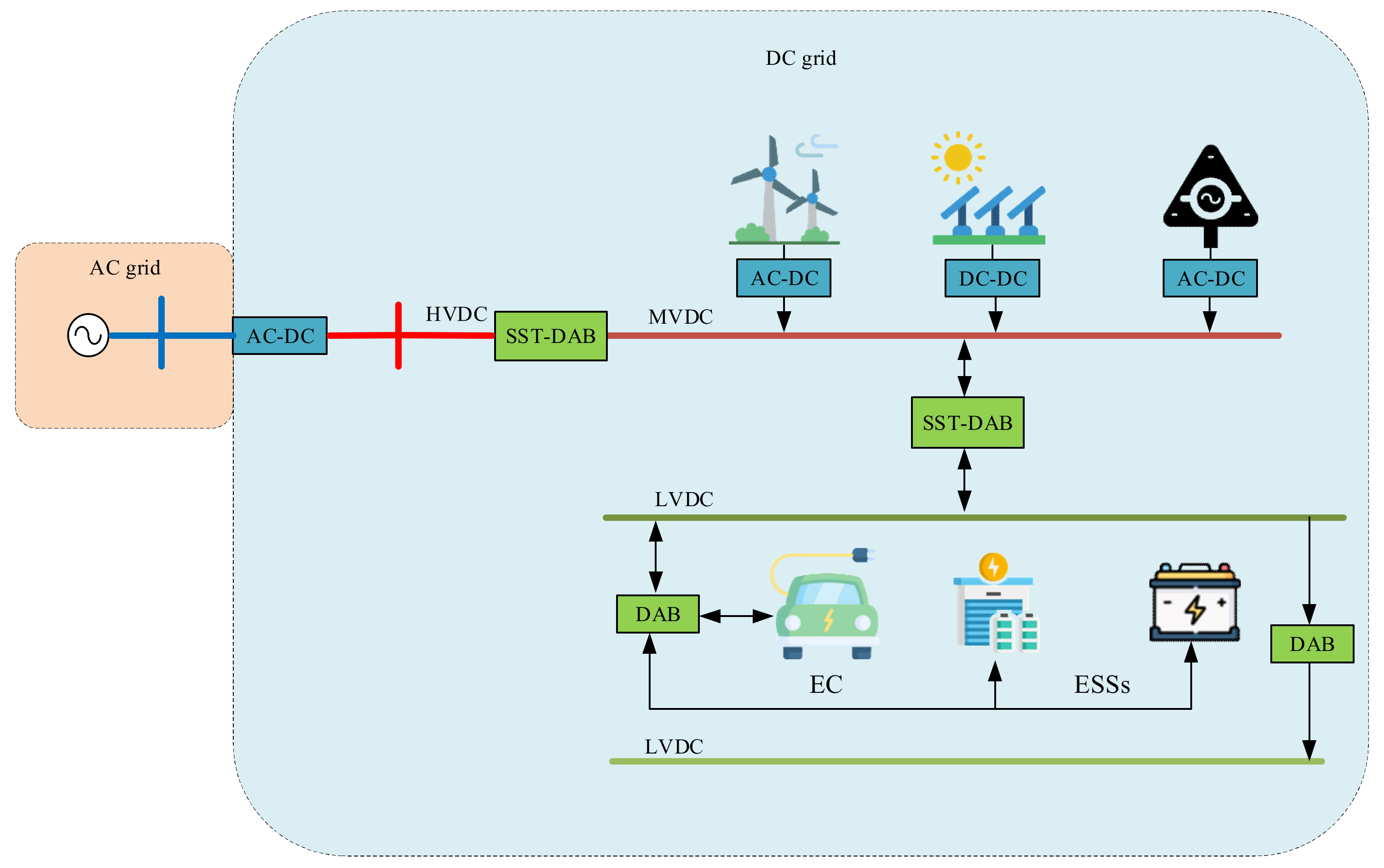
17]. The DAB has been widely studied and applied as an interface between energy storage devices and DC grids [
18,
19], as well as in solid-state transformers (SSTs) and charging equipment for new energy vehicles [
20,
21,
22,
23,
24,
25], as illustrated in
Figure 1.
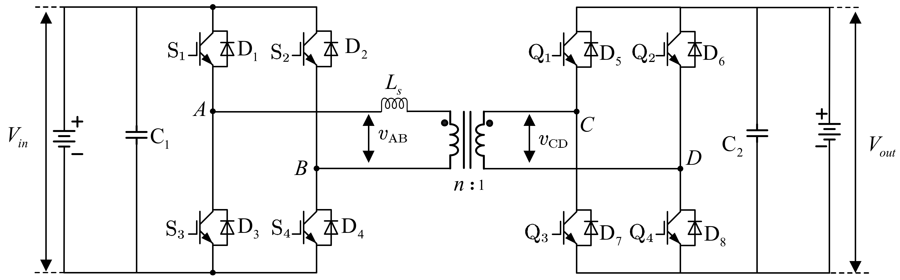
The basic topology of the DAB is depicted in
Figure 2. As can be observed from the figure, there are four power switches on each side of the high-frequency transformer, and the transformer provides isolation between the primary and secondary sides. The leakage inductance is represented by
. By controlling the magnitude and direction of the phase shift between the four bridge arms, energy can freely flow between the two DC power sources [
26,
27,
28,
29].
In all applications of the DAB, it is essential to first model the DAB converter and design the controller based on the specified steady-state and dynamic performance criteria according to the adopted modulation method. The objective of this paper is to provide a comprehensive review and comparison of different modeling methods, modulation methods, optimization algorithms, and control strategies for DAB converters. Furthermore, it aims to offer promising research directions for researchers who are newly engaged in DAB studies.
The remaining sections of this paper are organized as follows.
Section 2 introduces and compares the classical modulation method for DAB, namely, phase-shift modulation, and the recently proposed modulation method, asymmetric duty modulation.
Section 3 presents an overview of the current modeling methods for DAB, including reduced-order modeling, generalized state-space averaging modeling, discrete-time modeling, and general modeling based on the Fourier series, followed by a comparative analysis of these modeling methods.
Section 4 provides a comprehensive review and comparison of various optimization approaches and algorithms employed to address optimization problems in DAB, including the KKT approach, genetic algorithms, particle swarm algorithms, and Q-learning algorithms.
Section 5 summarizes and compares advanced control algorithms for DAB, including genetic voltage feedback control, model predictive control, model reference adaptive control, and active disturbance rejection control. Finally, the paper concludes with a summary and outlook on future research directions in DAB.
2. Modulations of DAB
To enhance the efficiency of DAB operation, the development of modulation strategies has progressed from single-degree-of-freedom approaches to multi-degree-of-freedom strategies, which in turn has facilitated advancements in DAB control methods. During the initial stages of research, the focus of DAB modulation strategy studies primarily centered on phase-shift modulation. A large number of scholars extensively investigated various phase-shift modulation (PSM) strategies in terms of converter circulating power, RMS current, soft-switching range, and power transmission range. In recent years, with the introduction of asymmetric duty modulation (ADM), scholars have continued to analyze the operational characteristics of DAB under this modulation scheme and further enhanced the DAB efficiency by combining it with PWM. Therefore, this section provides a comprehensive review of the various modulation strategies for DAB discussed in the existing literature.
2.1. Phase-Shift Modulation Strategy
The PSM is the most widely used modulation method in the context of dual active bridge (DAB) converters. It can be classified into several categories, including single-phase shift (SPS), extended-phase shift (EPS), dual-phase shift (DPS), and triple-phase shift (TPS). SPS modulation is the most fundamental and widely adopted method in DAB converters [
13,
30]. However, its applicability is limited in the case of non-matching input–output voltage ratios and transformer turns ratio, as it is difficult to achieve zero-voltage switching (ZVS) and can result in significant circulating power [
31,
32,
33]. Subsequently, EPS and DPS modulation methods were proposed by researchers to overcome these limitations and improve the converter’s performance in terms of circulating power, current stress, and ZVS range [
34,
35,
36]. The TPS modulation method, proposed in [
37,
38], represents a generalized version of all the PSM methods, and other PSM methods can be considered as special cases of TPS. Although TPS modulation introduces more operating modes and complexity, it offers several advantages, including minimum current stress, minimum power loss, larger ZVS range, and higher power factor, which make it suitable for various applications [
39,
40,
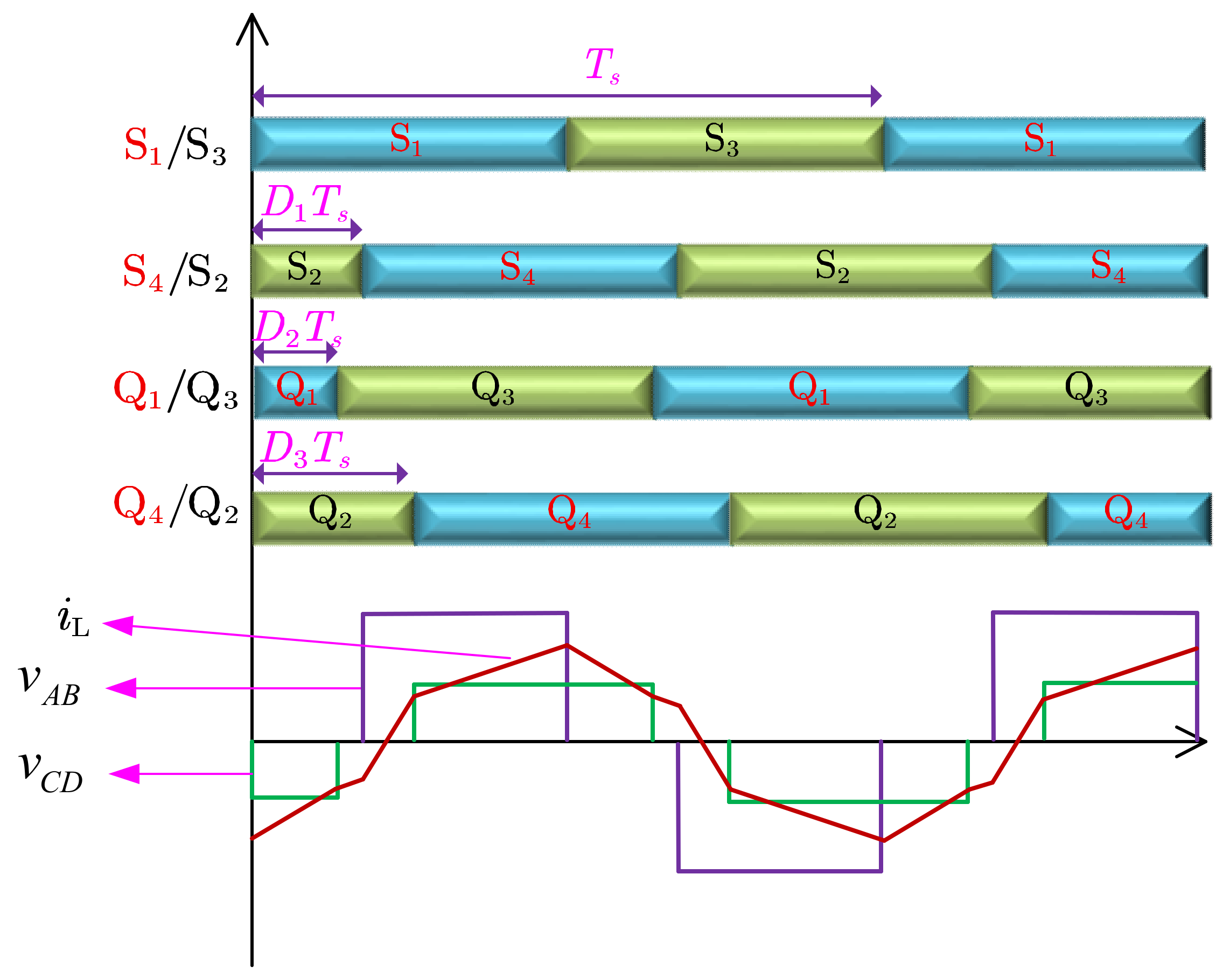
41]. As all modulation methods can be viewed as special cases of TPS, the TPS modulation waveform is presented in
Figure 3, without individual descriptions of other methods.
Assuming is defined as the phase-shift ratio, where represents the phase-shift time and denotes the half-period duration. represents the internal phase-shift ratio on the primary side of the DAB, represents the phase-shift ratio between the primary and secondary sides, also known as the external phase-shift ratio, and represents the internal phase-shift ratio on the secondary side. When and , it corresponds to the single-phase-shift modulation. When either or , it corresponds to the extended-phase-shift modulation. When , it corresponds to the dual-phase-shift (DPS) modulation.
2.2. Asymmetric Duty Modulation Strategy
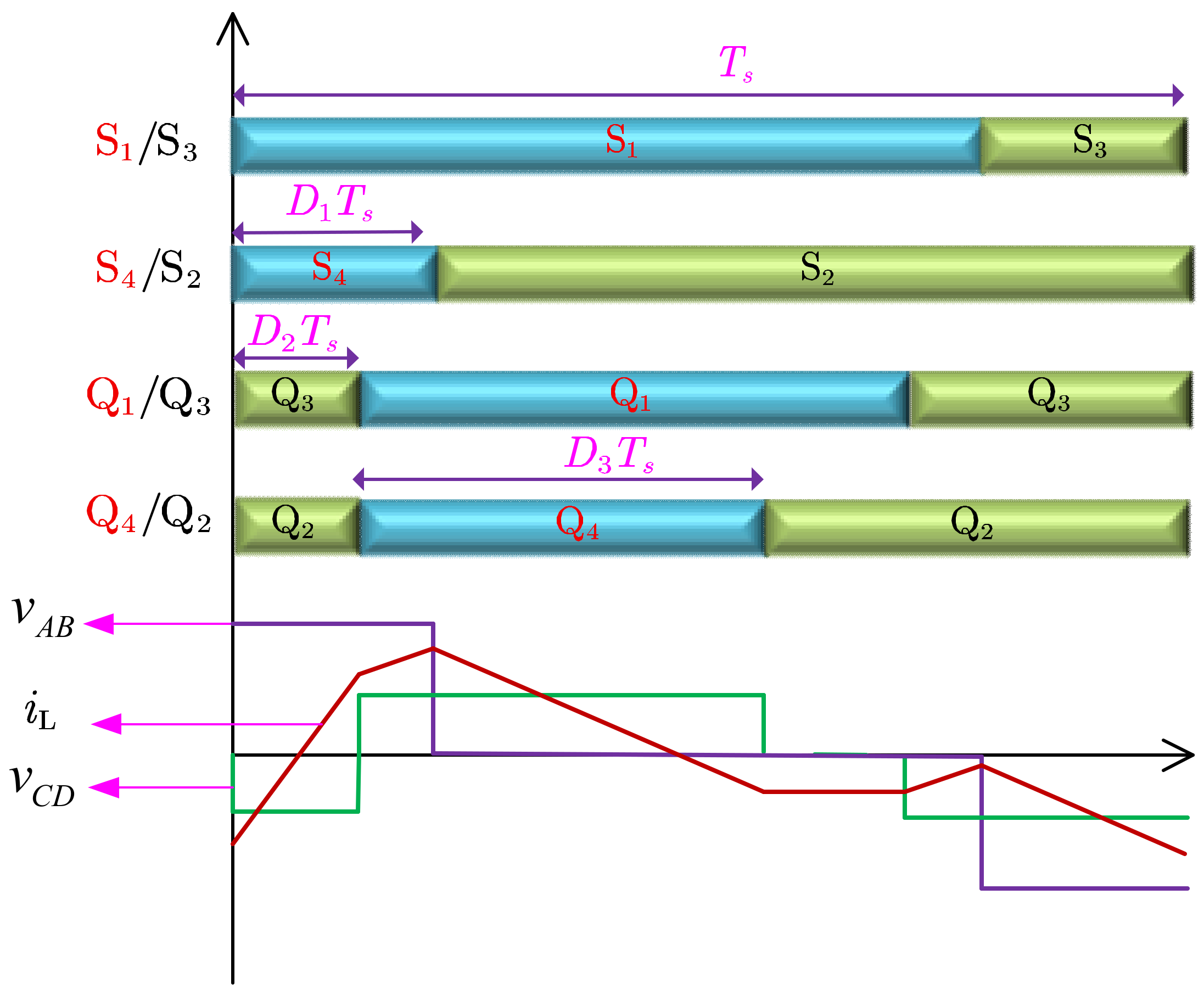
The asymmetric duty modulation (ADM) strategy is an extension of the phase-shift modulation strategy. From
Figure 3, it can be observed that all eight power switches in the DAB remain conducting for half a switching period, and in the phase-shift modulation strategy, the switches within the same bridge arm have the same conduction time. The asymmetric duty modulation strategy allows for different conduction times for switches within the same bridge arm, thereby adding three additional control degrees of freedom. The typical waveform of the ADM is shown in
Figure 4.
In the ADM strategy, the switches on one bridge arm are not triggered in a complementary fashion with a 50% duty cycle. Specifically, for the primary side, the conduction times of switches and are equal, while the conduction times of switches and are equal. The conduction times of and are less than half a period and are denoted as , whereas the conduction times of and are greater than half a period. Similarly, for the secondary side, the conduction times of switches and are equal, and the conduction times of switches and are equal. The conduction times of and are less than half a period and are denoted as D3, while the conduction times of and are greater than half a period. Additionally, there is a phase shift between the conduction times of and . It can be observed that when , ADM essentially becomes PSM. In other words, PSM is a special case of the ADM strategy. The contrast between ADM and PSM resides in the steady-state waveforms produced by PSM, which exhibit symmetry within half a period, resulting in high-frequency AC voltages on both the primary and secondary sides of the transformer containing two zero-voltage segments within one switching cycle. In contrast, the high-frequency AC voltage in ADM displays asymmetry within half a period, containing only one zero-voltage segment within each switching cycle.
The ADM strategy was initially proposed in [
42], but its application in efficiency optimization of the DAB was not studied. In [
43], ADM was only introduced on the primary side, and the ZVS conditions under four operating modes were analyzed. The authors of [
44] proposed a method utilizing the ADM to reduce the peak inductor current. The optimization objective in this scheme is chosen as the peak current, which can be considered as an indicator of the RMS current to some extent. Due to the simplicity of the peak current model and the absence of variable coupling, the computational complexity is greatly reduced. Under light load conditions, the asymmetric pulse width modulation exhibits a smaller RMS current compared with PSM, while under medium and heavy load conditions, the RMS current is larger than that of PSM. To address the problem of narrow soft-switching range and low efficiency of the PSM method over a wide voltage range and under light load conditions, the authors of [
45] proposed a unilateral asymmetric duty ratio modulation. The unilateral asymmetric modulation strategy combines the advantages of PSM in terms of Ohmic losses and ADM in terms of soft-switching range. ADM is employed on one side while PSM is used on the other side, achieving comprehensive performance optimization under light-load and voltage mismatch conditions.
2.3. Comparison of Modulation Strategy
Different modulation strategies need to be compared in terms of control difficulty and converter operating characteristics. It is desirable to achieve satisfactory operating characteristics with relatively simple controllers. As the degree of freedom in DAB control increases, the controller design becomes more complex, but the increased flexibility in control degrees allows for more satisfactory DAB operating characteristics. Therefore, the selection of an appropriate modulation method should consider the design conditions. PSM, as it can be classified under the TPS framework, exhibits the characteristic of adjusting phase shift without adjusting the conduction duty cycle of the switches, resulting in waveforms with half-cycle symmetry. PSM has a maximum of three control degrees of freedom, making the controller design relatively simple. However, due to the symmetric nature of the TPS framework, zero-voltage switching (ZVS) operation is lost when there is poor voltage match between the DC bus and the energy storage system, leading to increased switching losses. Furthermore, the inclusion of a substantial quantity of reactive power components raises the RMS of the inductor current, leading to increased conduction losses. Consequently, this decrease in conversion efficiency becomes particularly pronounced when operating under light-load conditions. ADM itself possesses three degrees of freedom, and when combined with phase-shift modulation, it can achieve up to six degrees of freedom. Due to its asymmetric control nature, the controller design becomes more complex. However, ADM can achieve lower RMS current compared with PSM under the same power transmission, wider soft-switching range under voltage mismatch conditions, and higher efficiency under light-load conditions. Moreover, ADM also faces inherent challenges such as complex current stress or RMS current mathematical modeling and variable coupling, making the analytical solution for the optimal solution difficult and online calculations challenging. Additionally, due to the presence of even harmonic components in voltage and current under the ADM scheme, the calculations and optimization results based on the fundamental component analysis model may be inaccurate.
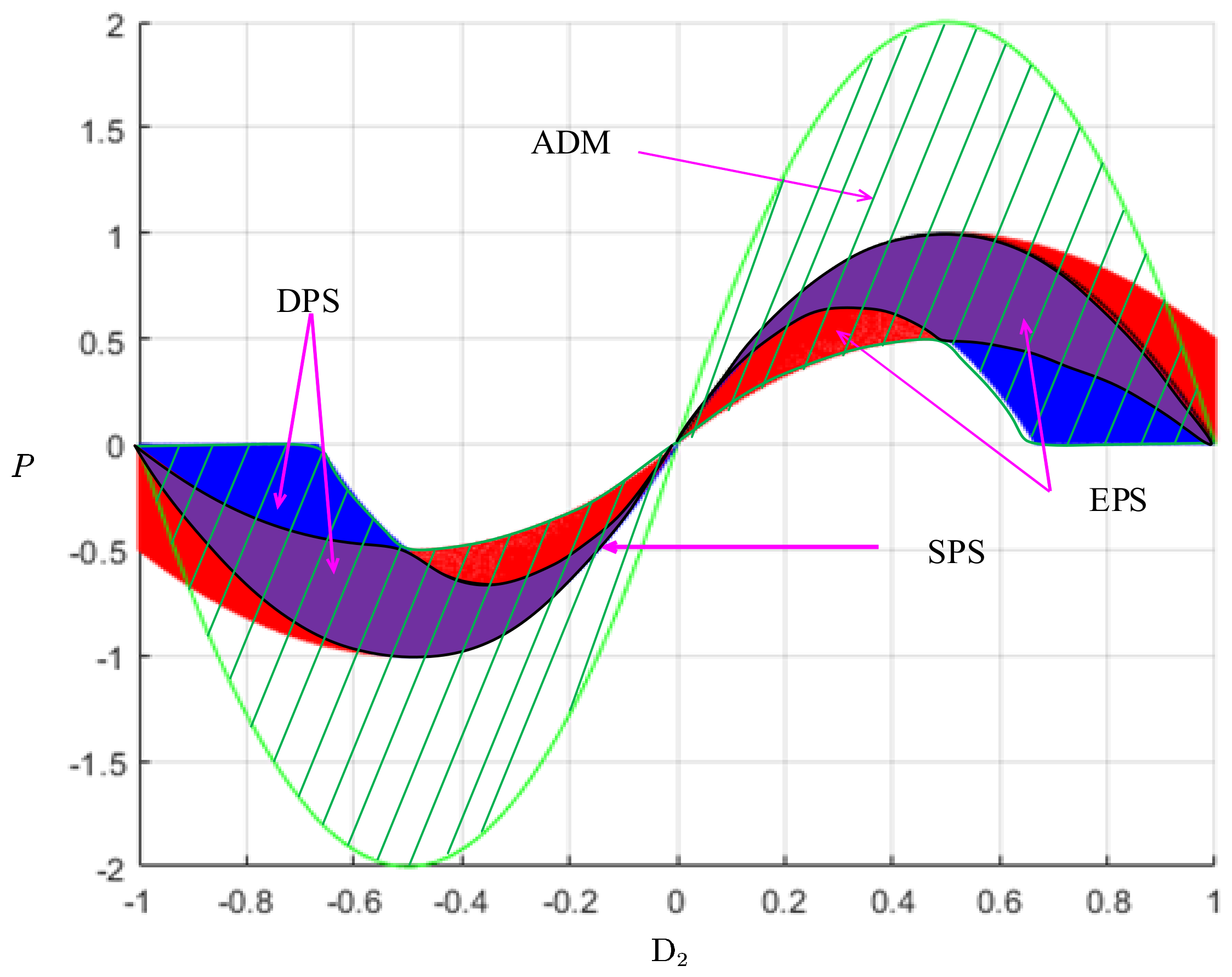
The simulation analysis of output power flexibility for different modulation methods is depicted in
Figure 5. The vertical axis represents the transmitted power, while the horizontal axis signifies the external phase-shift ratio value, denoted as
. For a given transmitted power, SPS modulation corresponds to two specific phase-shift ratio values,
. The blue region and the purple region, overlapping with both blue and red, represent the power characteristic range under DPS modulation. In comparison to SPS modulation, DPS modulation exhibits an infinite number of combinations of phase-shift ratio values, denoted as
and
, for the same transmitted power. This significantly augments the power regulation flexibility of the DAB, playing a crucial role in the coordinated optimization of various characteristics. The red and purple regions represent the power range under EPS modulation, which also boasts a high degree of flexibility. The green region signifies the power regulation range under the ADM modulation. It is evident that the ADM modulation not only enhances regulation flexibility but also extends the power range, rendering it an ideal modulation approach.
3. Modeling of DAB
The modeling plays a significant role in analyzing power electronic circuits. On one hand, the establishment of converter models enables a clear analysis of the interrelationships among various physical quantities. On the other hand, when applying classical control theory to analyze nonlinear systems like power electronic circuits, it is typically necessary to first develop a large-signal model and then linearize it to establish a small-signal model for further analysis. Currently, there are four main modeling methods for DAB converters. Among them, the reduced-order modeling method is widely applied in DAB-related research due to its simplicity and clear representation of the DAB converter’s operation process. The remaining three methods, namely, state-space averaging, generalized state-space averaging, and discrete-time modeling, have also found applications in the design of DAB controllers.
3.1. Reduced-Order Modeling
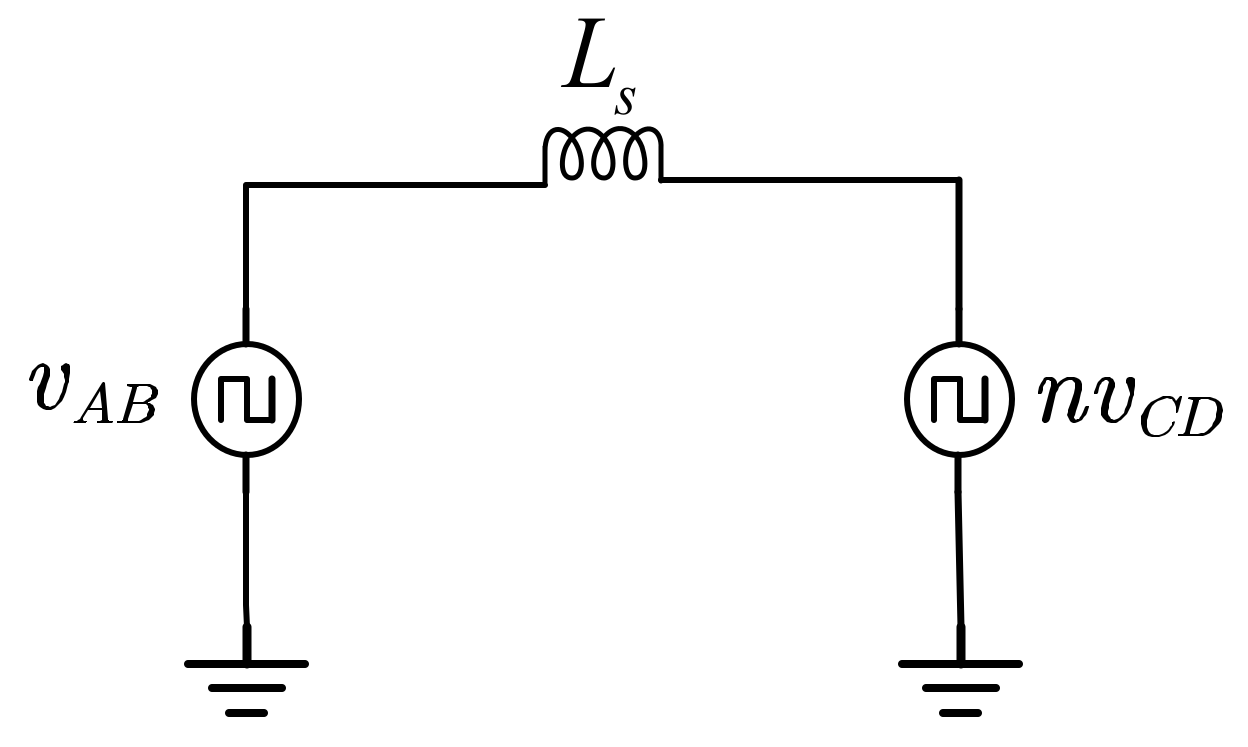
By neglecting the dynamic variations in transformer currents and considering the transformer as an ideal component, with the assumption of sufficiently large capacitors on the source and load sides, the DAB can be simplified to a first-order model, as illustrated in
Figure 6 [
46,
47,
48].
Subsequently, the basic operating modes of the DAB were analyzed, and the models for each operating mode were established in the time domain. Based on the boundary conditions at the switching instants, the overall average value model was constructed, and the small-signal model was developed to obtain the system transfer function. The transfer function of the DAB is a first-order model, which reflects the steady-state behavior of the DAB while ignoring its dynamic characteristics. The following is the reduced-order model of DAB using the SPS modulation method.
Introducing the switch state function:
When the power switches
and
are turned on,
; when the power switches
and
are turned on,
. When the power switches
and
are turned on,
, and when
and
are turned on,
. Due to the dependence of the inductor current polarity on the switching state of the power switches, the states are classified into six categories in the analysis. However, since some circuit state variables remain unchanged between certain stages, the calculation of the mathematical model for the steady-state power of the DAB converter can be divided into four stages. Then, a unified model for the inductor current can be established:
Based on Equation (3), the
current in each of the four operation modes can be obtained. By utilizing the DAB power definition equation within a single switching period, the DAB power transmission expression can be derived under SPS modulation:
The expressions for the average currents on each side can then be obtained as follows:
Building on the steady-state model described above, the following expressions are obtained by adding the small perturbation signals
,
,
, and
while ignoring higher-order terms:
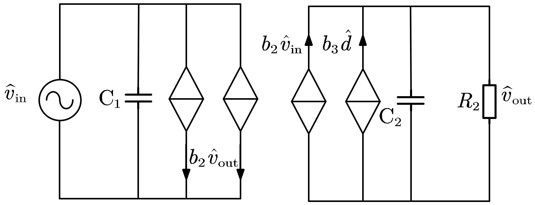
Based on Equation (6)
and
, the small signal model of DAB is obtained, and the equivalent circuit diagram is shown in
Figure 7.
Based on the equivalent circuit diagram, the transfer functions between variables can be obtained:
3.2. Generalized State-Space Averaging Model
The generalized state-space averaging method was proposed to address the limitations of the traditional state-space averaging method in describing the variations in AC quantities [
49]. By considering higher-order Fourier coefficients of the state variables, the generalized state-space method can closely approximate the actual waveforms, capturing significant ripple components and higher-frequency oscillations. In [
50], the generalized state-space averaging modeling approach was first applied to DC-DC converters. The traditional state-space averaging method neglects high-frequency fluctuations in power electronic circuits. In the case of the DAB converter, the inductor current exhibits significant variations. Applying the state-space averaging method requires a reduction in the model order, which compromises accuracy and fails to capture the dynamic response of the inductor current. Therefore, in [
51], the generalized state-space averaging modeling method was employed for the DAB converter. Based on the representation of waveforms using complex Fourier series, the periodic variable
can be expressed as a Fourier series, and the generalized averaging method is applied:
In the equation,
represents the fundamental angular frequency, and
is the sliding average coefficient obtained by moving a time window with a width of
along the time axis. Its mathematical definition is:
Two fundamental properties can be derived from Equations (8) and (9), as shown below:
This property signifies that the derivative of a function’s Fourier series coefficients can be expressed by first differentiating the function and then taking its Fourier series coefficients. As a result, the Fourier series coefficient equation corresponding to the state variable equation can be established.
Another property of the Fourier transform is its frequency domain convolution property, which is mainly used in power electronics converter applications to convert the Fourier series coefficients of the product of switch variables and state variables into the product of their respective Fourier series coefficients.
For systems with insignificant ripple, the fundamental and DC components of the Fourier series coefficients can accurately reflect the variations in the state variables. Therefore, it is sufficient to consider
,
. Since the Fourier coefficients for
and
are complex conjugates, the real and imaginary parts of the k = 1 coefficient can be used to represent the Fourier coefficients for
. By incorporating Equation (11), the Fourier coefficient equations for the system can be derived:
Finally, the Equation (12) is applied to the state equation of the DAB converter to establish its small-signal model.
3.3. Discrete-Time Modeling
The discrete-time modeling method is also capable of capturing the high-frequency dynamic behavior of DAB and has been widely employed in power electronics modeling [
52,
53,
54,
55]. As demonstrated by the generalized averaging model approach discussed earlier, it is based on continuous-time function models. In contrast, for discrete-time modeling, the discrete state equations are obtained by sampling the DAB at different time instances, resulting in changes to the coefficient matrix of the differential equations in the state equation. In the case of discrete modeling for DAB under SPS modulation, four different switching states are utilized for discrete sampling, and the previous switching state is used to represent the next switching state. Through iterative iterations, the final discrete state equations are obtained, and by applying the Z-transform, the transfer function of the discrete system can be derived.
The continuous model of DAB can be obtained through the modeling of the state variables:
The coefficients of the state variables, , , , , and , , , , under different switching states can be obtained from the switching function.
The solution to the continuous state equation is generally expressed as:
where
. Specifically for DAB, considering only one period of
, there are four switch states:
where
represents the phase shift angle,
,
,
,
.
Substituting Equation (16) into Equation (15) with DAB’s four states as discrete intervals yields provides the following:
By repeatedly iterating (17), a general discrete expression can be obtained:
3.4. General Modeling Based on Fourier Series
It can be seen from the previous three modeling methods that different modulation methods require the establishment of corresponding models. Advanced modulation methods offer a greater number of controllable variables. However, as the controllable variables of the high-frequency link increase, the system model changes with different time periods and operating states, making it quite complex to establish a model that can be uniformly described. References [
56,
57] provide a unified description of the DAB high-frequency link characteristics based on Fourier analysis and establish a unified model for DAB under different modulation methods.
The modulation techniques of SPS, DPS, and EPS can be seen as particular cases that fit into the wider framework of TPS modulation, and they can be represented in a unified form. The high-frequency link voltages exist in three different phase-shift variables: , , and . Here, and are the internal phase angles of the primary and secondary sides, respectively, while represents the external phase shift between the primary and secondary sides. SPS, DPS, and EPS can all be considered as special cases of this form, where is applied for SPS modulation, is applied for DPS modulation, and or is applied for EPS modulation.
The primary and secondary side high-frequency link voltages can be expressed in Fourier series as:
The equation for leakage inductance current can be derived by:
Based on Equations (19) and (21), we can obtain a unified transfer power function for the high-frequency link:
Equations (19), (21) and (23) provide the time-varying behaviors of voltage, current, and instantaneous power at each frequency component, which together form the high-frequency link voltage, current, and power. These results are consistent with the ones obtained from the reduced-order modeling analysis. Thus, the steady-state model can be used to derive the DAB small-signal model.
3.5. Comparison of Modeling Methods
In this section, a comparison of different modeling methods is conducted based on their application scenarios and modeling accuracy.
Regarding the application scenarios, the reduced-order modeling method is employed in three areas. Firstly, it is used to analyze the steady-state characteristics of the DAB under different modulation methods [
34,
58,
59]. The reduced-order modeling method effectively expresses the relationships between electrical quantities in the DAB circuit, enabling a detailed description of the operating states. Secondly, this method establishes mathematical models for optimization strategies with fewer variables [
45,
60,
61]. Lastly, it is employed in the design of control methods based on Proportional–Integral (PI) controllers [
62,
63,
64,
65,
66,
67]. By developing a reduced-order model that expresses the average values of output power, output current, output voltage, and phase shift angle, small-signal models can be derived to establish transfer functions, facilitating controller design. The generalized state-space averaging method finds applications in advanced control methods. In [
68,
69], this method is employed to establish an adaptive model under TPS modulation, followed by the design of an adaptive controller. The generalized state-space averaging model provides information about the dynamic response characteristics of the DAB. By formulating the generalized state-space equations of the system and performing linearization, transfer functions or state-space models can be obtained. The model is useful for analyzing system frequency response, stability, and control design. Discrete-time modeling is primarily applied in DAB model predictive control. In [
47,
70], the discrete-time model is used to construct predictive models for predicting the future behavior of the system. By utilizing a discrete-time model of the DAB, in combination with current measurements and control inputs at the current time, one-step or multi-step predictions of the DAB operating states can be made. The general modeling method based on the Fourier series is mainly employed to establish mathematical models for optimization strategies with multiple variables [
44,
71,
72].
Regarding modeling accuracy, reduced-order modeling is a technique to simplify complex system models. It achieves this by neglecting certain high-order dynamics or nonlinear characteristics of the system, reducing the model to a lower-order one. Although the DAB is simplified to a lower-order model, it does not compromise the accuracy of the model, as this is determined by the inherent characteristics of the DAB topology [
73]. In the case of the generalized state-space averaging method, while a full-order model theoretically should achieve higher accuracy, the accuracy may be compromised when significant harmonic distortions are present since the full-order model is based on the first harmonic only [
74]. Discrete-time modeling methods can provide higher modeling accuracy, particularly suitable for dynamic behavior analysis and control design of the system. The general modeling method based on the Fourier series is theoretically the most accurate and general modeling method. However, in practical systems, high-order effects are often neglected to trade off accuracy for practicality. The accuracy of the four modeling methods is further verified through simulation. The DAB simulation parameters are shown in
Table 1.
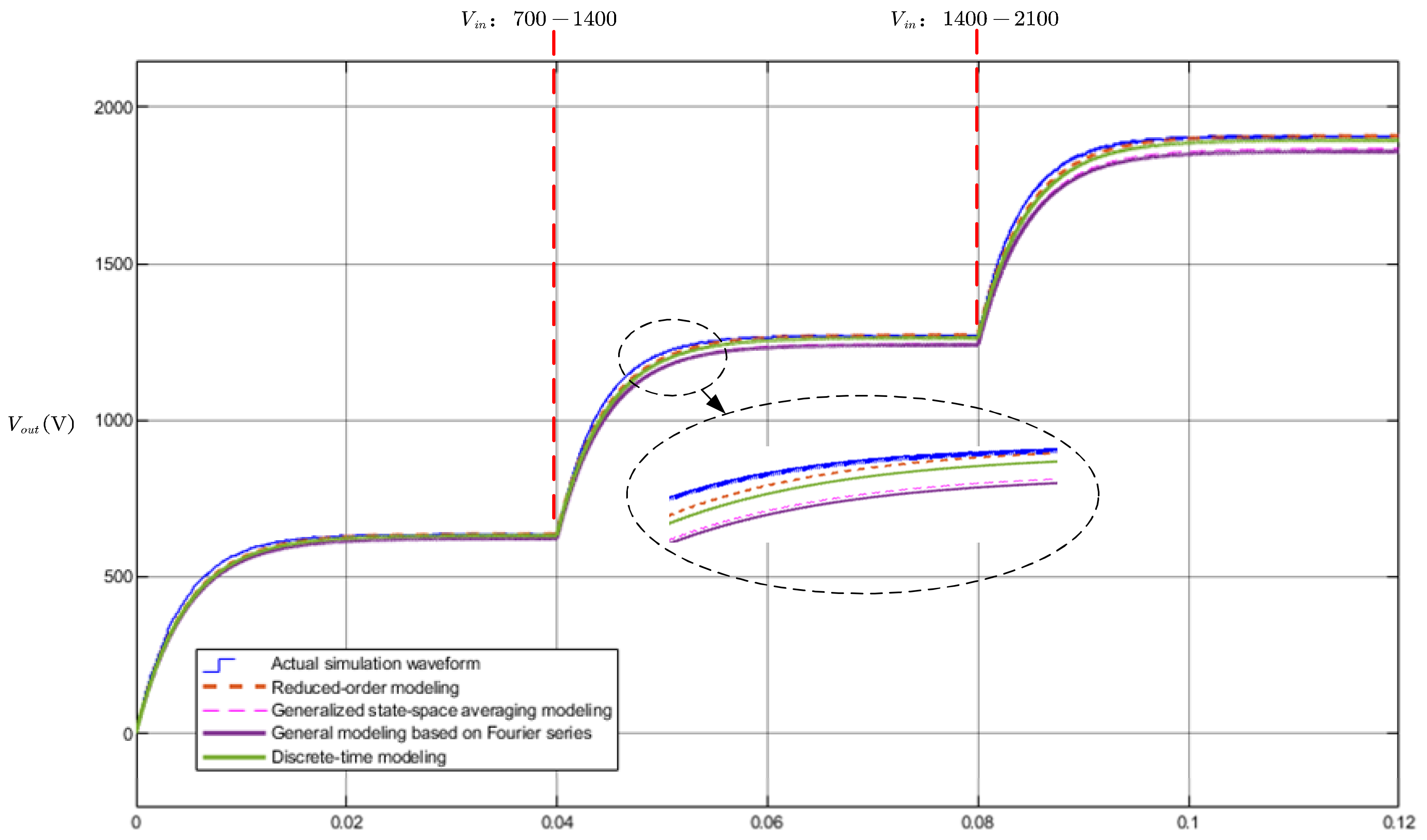
Figure 8 illustrates the comparative results between different modeling methods and the actual model. The accuracy of these methods in reflecting the output voltage
is evaluated by varying the input voltage
. At t = 0.04, the input voltage rises from 700 V to 1400 V, and at t = 0.08, it changes from 1400 V to 2100 V. From
Figure 8, it can be observed that the reduced-order modeling method exhibits the highest precision with no steady-state error compared with the actual model. The discrete-time modeling method incurs a relatively small steady-state error. On the other hand, both the generalized state-space averaging and Fourier series-based generalized modeling methods display lower accuracy, primarily due to the consideration of only the fundamental harmonic component. These simulation results are in alignment with theoretical analyses.
In summary, the choice of modeling method depends on the specific application scenario and the desired modeling accuracy. Reduced-order modeling techniques are suitable for analyzing steady-state characteristics, establishing optimization models with fewer variables, and designing control methods. The generalized state-space averaging method is employed in advanced control techniques, providing insight into dynamic response characteristics. Discrete-time modeling is utilized in DAB model predictive control, enabling predictions of future system behavior. The general modeling method based on the Fourier series is applied to establish mathematical models for optimization strategies with multiple variables. The accuracy of each modeling method varies, with reduced-order modeling sacrificing some accuracy for simplicity, while discrete-time modeling provides higher accuracy, and the general modeling method based on the Fourier series offers the most accuracy in theory but may neglect higher-order effects for practicality.
4. Optimization Algorithms
The high-efficiency operation of the DAB converter is a key technical challenge in power conversion and application. Optimization objectives such as minimizing inductor current stress, reducing losses, optimizing the circulating power, and expanding the soft-switching range are commonly pursued in order to improve transmission efficiency and related performance. Through the combination of different modulation methods and solving algorithms, a variety of optimal modulation strategies are proposed. The traditional methods for solving the optimization problem of the DAB converter are mainly based on the Karush–Kuhn–Tucker (KKT) conditions using the Lagrange multiplier approach, later referred to as the KKT approach. In recent years, numerous intelligent algorithms, such as swarm intelligence optimization and reinforcement learning algorithms, have been proposed successively to solve DAB performance optimization problems under different modulation methods. These solution algorithms have opened up new technical avenues for DAB converter efficiency optimization and have become promising research directions. In the following sections, the current research status of the KKT approach, swarm intelligence optimization, and reinforcement learning algorithms in solving DAB modulation optimization problems will be reviewed and analyzed.
4.1. KKT Approach
Initially, most optimization strategies for modulation in the DAB converter were primarily based on the Lagrange Multiplier Method (LMM) [
61,
75]. The KKT approach can be considered as an extension of the LMM. In the context of the optimization problem in DAB, the KKT algorithm constructs a Lagrangian function to convert the inequality constraints into equality constraints, thereby transforming the optimization problem into solving a set of nonlinear equations. By solving this set of nonlinear equations, the optimal solution and Lagrange multipliers can be obtained, enabling the derivation of the optimal control strategy for the system. The application of the KKT approach to the optimization modulation algorithm for the DAB can be described as follows:
where
, the objective function
represents different optimization objectives such as the current stress characteristic function, and circulating power characteristic function, among others. Here,
denotes the number of switching modes. The equality constraint is represented by
, while
represents the inequality constraints determined by operational constraints of effective switching modes. The number of inequality constraints is denoted by
. Mathematically, the local minimum point
satisfies the KKT conditions, which can be described as follows:
where
is the Lagrangian function, and
as well as
are defined as the KKT multiplier.
In Reference [
76], under the constraint of full-range soft-switching conditions, the KKT algorithm is employed to determine the phase-shift angles D1, D2, and D3 for the TPS modulation method, aiming to minimize the inductor current stress. Reference [
44] proposes a variable duty cycle modulation approach to minimize the peak-to-peak current of the inductor for the DAB converter in four different operating modes. The KKT algorithm is applied to solve this optimization problem. Furthermore, Reference [
60] presents an optimization scheme using EPS modulation to reduce the circulating power in DAB converters. The KKT method is employed to obtain the optimal solution.
The KKT method is proficient in handling convex optimization problems. However, it also possesses limitations. Specifically, when applied to DAB optimization, the KKT method requires separate optimization for different operating modes, thereby increasing the complexity of the solution process. For instance, in the case of optimizing the TPS modulation, which encompasses a total of 12 operating modes, the values need to be recalculated and compared for all 12 modes whenever circuit parameters change, resulting in significant computational time. DAB is frequently employed as an interface for new energy generation and energy storage systems, characterized by stochastic and fluctuating behaviors. This dynamic nature causes rapid variations in the voltages on both sides of the DAB, and the computational time required for optimization algorithms can significantly affect the effectiveness of DAB optimization and control. As a result, most optimizations are limited to offline calculations, followed by the use of look-up tables in microprocessors for optimized operation. Furthermore, the KKT method can only optimize a single objective and does not facilitate the simultaneous optimization of multiple objectives. Consequently, in recent years, researchers have applied advanced algorithms to optimize DAB modulation strategies, aiming to achieve the coordinated optimization of circulating power, soft-switching range, current stress, and other characteristics of the DAB system.
4.2. Genetic Algorithm
The inception of the genetic algorithm (GA) can be attributed to its initial proposition by J. H. Holland in the year 1969. Genetic algorithms are a type of evolutionary algorithm that use principles inspired by natural selection to search for solutions to optimization problems. To apply a GA to the modulation problem in DAB converters, the problem must first be formulated as an optimization problem with a set of objective functions and constraints. The objective functions could include minimizing current stress, maximizing efficiency, or minimizing circulating power, depending on the specific requirements of the application. Once the optimization problem is formulated, the GA can be used to find the phase shift ratio that meets the desired objectives. The GA iteratively evaluates the fitness of each potential solution in the population, selecting the best solutions for reproduction and applying crossover and mutation operations to create new solutions.
For the multi-objective optimization modulation problem of DAB, it can be uniformly described as:
The objective functions, , in the context of DAB modulation, can represent characteristics such as current stress, circulating power, and RMS current of the inductor. The equality constraint, , is commonly used in DAB modulation to ensure that the actual transmitted power matches the desired transmitted power. The inequality constraint, , represents the constraints under different switching models. represents the zero voltage switching (ZVS) constraint. Equation (27) plays a crucial role in constructing the fitness function of the genetic algorithm. It is used to evaluate and select the generated offspring, making it a critical step in the optimization process of modulation using genetic algorithms.
A multi-objective efficiency optimization scheme based on a genetic algorithm and TPS modulation is proposed in Reference [
77]. This optimization scheme encompasses three objectives: minimizing RMS current, reducing current stress, and achieving ZVS performance. By employing a genetic algorithm, the proposed approach effectively tackles the non-convex optimization problem encountered in the multi-objective modulation of the DAB system. Reference [
78] introduces a genetic algorithm-based droop control method aimed at reducing power losses in DAB converters and thereby enhancing transmission efficiency. Furthermore, Reference [
79] presents the application of a genetic algorithm for multi-objective optimization modulation of modular DC-DC converters.
The genetic algorithm excels in addressing multi-objective cooperative optimization problems and non-convex optimization problems that cannot be directly solved by using the KKT approach. However, its search capability is limited, and it imposes high demands on parameter settings. When there are variations in circuit parameters, corresponding adjustments to algorithm parameters are required. Furthermore, in the online computation of optimized modulation for DAB converters, real-time and dynamic considerations are necessary. The search process of genetic algorithms typically involves a substantial number of iterations and fitness evaluations, which may lead to high computational complexity and difficulty in meeting real-time requirements.
4.3. Particle Swarm Optimization Algorithm
The Particle Swarm Optimization (PSO) algorithm was initially proposed by J. Kennedy and R. Eberhart in 1995 [
80]. Both PSO and genetic algorithms are regarded as swarm intelligence search algorithms, with their core lying in the construction of the fitness function. For the optimization modulation problem of DAB, the fitness function can be constructed based on Equation (27), and the specific construction method is elaborated upon in Reference [
71]. Here, a concise overview of the fundamental concept of PSO is presented. In the PSO algorithm, each solution to be optimized can be conceptualized as a particle, and the motion state of a particle is represented by its position and velocity. The particle’s position denotes the parameter values of the solution to be optimized, i.e.,
, while its velocity, denoted as
, represents the search direction and step size of the particle in the solution space. The particle’s motion state is influenced by the historical best position of the particle itself and the swarm’s historical best position. Throughout the search process, particles continuously update their positions and velocities in order to discover more favorable solutions. The formulas for updating a particle’s position and velocity are as follows:
where,
represents the velocity of the
i-th particle in the
d-th dimension,
represents the position of the
-th particle in the
-th dimension,
represents the historical best position of the entire group,
is the inertia weight,
and
are the individual and social learning factors of the particle, and
and
are random numbers in the range of
. By continuously updating the positions and velocities of particles, PSO can search for optimal solutions in the solution space.
A modulation strategy for optimizing the reflux power based on the TPS modulation method and a unified model using the Fourier series was proposed in Reference [
71]. The PSO algorithm was utilized to solve for the phase-shift angle corresponding to the minimum circulating power. This method also increased the ZVS range in the DAB converter and reduced switching losses. Reference [
79] presented a multivariable optimization modulation strategy solved using the PSO algorithm. This optimization modulation strategy included phase-shift modulation with PWM, effectively reducing the root mean square current of the DAB converter. In Reference [
81], the PSO algorithm was employed to find the optimal phase-shift angle under the TPS modulation strategy to minimize the root mean square current across the entire operating range. However, this optimization scheme did not consider the ZVS performance of the DAB converter, resulting in significant switching losses. The PSO algorithm can be combined with other algorithms to overcome the problem of falling into local optima. Reference [
82] proposed an EPS modulation strategy based on a combination of GA and PSO algorithms to optimize the circulating power of the DAB converter. Furthermore, Reference [
83] utilized both the PSO algorithm and the LMM method to optimize the transmission efficiency of the DAB converter. The PSO algorithm was applied for local optimization, while the LMM method was used for global optimization.
Compared with GA, PSO exhibits faster convergence speed and lower parameter dependence. However, it is prone to becoming trapped in local optima and requires significant computational resources, particularly in high-dimensional and complex problems, which necessitates longer computation time and higher computational precision. The existing literature addresses this issue by employing offline calculations followed by table look-up methods for implementing optimization control in DAB systems.
4.4. Q-Learning Reinforcement Learning Algorithm
The Q-learning algorithm, as a classic method in reinforcement learning, is an approach that utilizes temporal differences to solve reinforcement learning control problems [
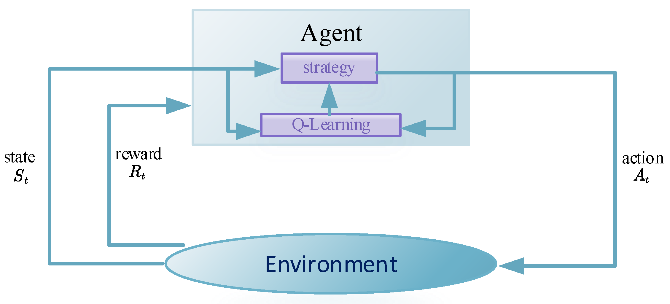
84]. Its principles can be illustrated as shown in the diagram below.
Figure 9 illustrates the basic framework of the Q-learning reinforcement learning algorithm, which is a trial-and-error approach aimed at gradually improving the decision-making capabilities of the agent. During each training episode, the agent, based on the current state
, selects an action
. Subsequently, it receives a corresponding reward and transitions to the next state
. The objective of the agent is to discover the optimal policy in each discrete state to maximize the expected discounted cumulative reward. Through continuous interactions between the agent and the environment, an optimized policy corresponding to the maximum cumulative reward can be obtained. Q-learning employs the e-greedy method and the Bellman optimality equation to select new actions. Compared with other reinforcement learning algorithms, Q-learning features a simple Q-function that can be used online as the agent interacts with the environment. In the context of DAB optimization modulation, the Q-learning algorithm primarily aims to optimize the phase shifts
,
, and
corresponding to various performance metrics. It maintains a Q-value table to record the learned experiences and retrieves the optimal phase shift ratios based on the indices of the Q-value table.
Reference [
84] proposes an efficiency optimization modulation strategy based on a Q-learning algorithm and TPS. This method enhances the transmission efficiency of the DAB by optimizing the power loss rate under ZVS conditions. However, after the completion of Q-learning algorithm training, the corresponding optimization results need to be stored in a discrete lookup table, which makes continuous control inconvenient. To address this issue, Reference [
85] introduces an RL+ANN-based TPS modulation strategy. Firstly, the Q-learning algorithm is employed to solve for the optimization strategy corresponding to the minimum current stress in the DAB, and the optimization results are stored in the Q-table. Subsequently, the ANN algorithm is applied to fit this Q-table. Based on this, the trained ANN agent functions as a fast proxy predictor, providing continuous optimization modulation strategies for the DAB across the entire operating range. However, this RL+ANN approach involves two training processes, which increases the computational complexity and requires more training time. Due to the limitations of traditional optimization-based modulation strategies, which rely on mathematical models of the DAB, they may not provide optimal performance under complex operating conditions. The Q-learning reinforcement learning algorithm can learn modulation strategies through trial-and-error and automatic optimization, specifically tailored to the operating environment, thereby achieving optimal performance.
4.5. Comparison and Application Suggestions of Different Advanced Algorithms
In this section, a comparison of the aforementioned advanced algorithms is conducted, and the following metrics are proposed: A. Algorithm application complexity, B. Optimization speed, C. Environmental adaptability, D. Multi-objective optimization capability, and E. Ability to achieve online continuous optimization. Subsequently, application recommendations are provided for different modulation methods.
Table 2 compares various advanced algorithms and some combination algorithms based on the aforementioned metrics.
From
Table 2, it can be observed that the KKT method is applicable to simple modulation techniques such as DPS and EPS, which have relatively straightforward circuit operating modes and enable the establishment of KKT optimization models. However, it may not be suitable for multi-objective optimization problems. The GA algorithm exhibits moderate performance across various modulation techniques and working environments; therefore, it can be employed for diverse applications in DAB. The PSO algorithm demonstrates excellent environmental adaptability, enabling it to adjust to changes in circuit parameters without frequent parameter tuning, unlike the GA algorithm. However, due to its tendency to converge to local optima, it is beneficial to combine PSO with other algorithms to address premature convergence issues. Promising approaches include the hybrid GA+PSO and PSO+KKT algorithms. Additionally, the Q-learning algorithm, based on reinforcement learning, exhibits robust environmental adaptivity and, when combined with ANN, can achieve online continuous optimization, providing it with a competitive edge.
5. Dynamic Control Method of DAB
In practical operation, the dynamic performance of a converter is also critical. When the operating conditions of the converter change, a fast dynamic response through the controller is required to bring the converter back to a stable state. A review and comparison of different control methods, including Feedback Control, Linearization Control, Feedforward Plus Feedback Control on Output Voltage, Disturbance-Observer-Based Control (DOBC), Feedforward Current Control (FFCC), and Model Predictive Current Control (MPC) is presented in Reference [
75]. Reference [
87] applied the generalized super-twisting algorithm to DAB control in aircraft battery systems. This algorithm ensures the robustness of control actions in the presence of current and voltage disturbances. The voltage tracking capability and load disturbance suppression performance were used as indicators for the various control methods. However, all the control methods were based on SPS modulation, and the combination of advanced modulation and control methods was not summarized. As discussed above, SPS modulation alone may not achieve efficient power transmission. Therefore, the combination of optimization modulation strategy and control methods is of great importance and is reviewed in this paper.
5.1. Generic Voltage Feedback Control for DAB
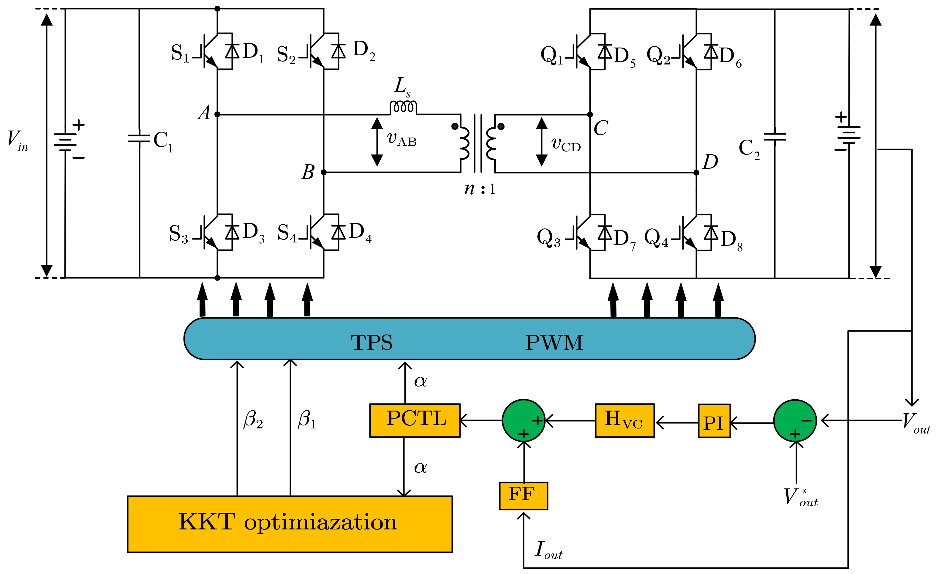
Reference [
88] proposes a control method called Generic Voltage Feedback Control (GVFC) that is applicable to different modulation strategies. The control structure under TPS modulation is shown in
Figure 10, which has three control degrees of freedom and can be used for corresponding control of any modulation method. The proposed control scheme includes a single voltage control loop and a PCTL block, where PCTL stands for Peak Current Tracking and Limiting. The function of PCTL is to avoid magnetic core saturation mainly by limiting the peak current by stopping the phase angle shift outward. Initially, the optimal internal phase angle is determined based on specific performance criteria. Subsequently, the feedback voltage is compared with the reference voltage using a comparator, and the resulting error is transmitted to the voltage controller. The voltage controller output, along with the feedforward controller, is then used to set the external phase angle. Then, the peak current is limited through the PCTL block, achieving balanced control without current sensors.
5.2. Model Predictive Control for DAB
Utilizing model predictive control (MPC) with DAB converters primarily revolves around employing a mathematical model of the converter for forecasting the system’s future dynamics and fine-tuning the control inputs to attain the desired performance objectives. In MPC, a finite-time horizon is defined over which the future behavior of the system is predicted, and a cost function is formulated to minimize the error between the predicted and desired outputs, as well as to satisfy any constraints on the control inputs and outputs. Once the model is established, a cost function is formulated that quantifies the performance objectives, such as minimizing the output voltage ripple, achieving a fast transient response, and maximizing efficiency. The cost function also takes into account any constraints on the control inputs and outputs, such as the maximum and minimum values of the switch duty ratio and the output voltage. Using the cost function and the model, an optimization problem is formulated and solved at each sampling instant to determine the optimal control inputs over the finite-time horizon [
89,
90]. The optimization problem can be solved using various techniques, such as quadratic programming or nonlinear programming.
The advantages of MPC applied to DAB converters include the ability to handle nonlinear dynamics and constraints, fast transient response, and the ability to predict and correct disturbances in real time. However, MPC requires significant computational resources and can suffer from numerical issues such as constraint violation or instability if the cost function or model is not well formulated [
91].
MPC has been incorporated to tackle the optimization control challenges encountered in DAB converters, as discussed in References [
70,
92,
93,
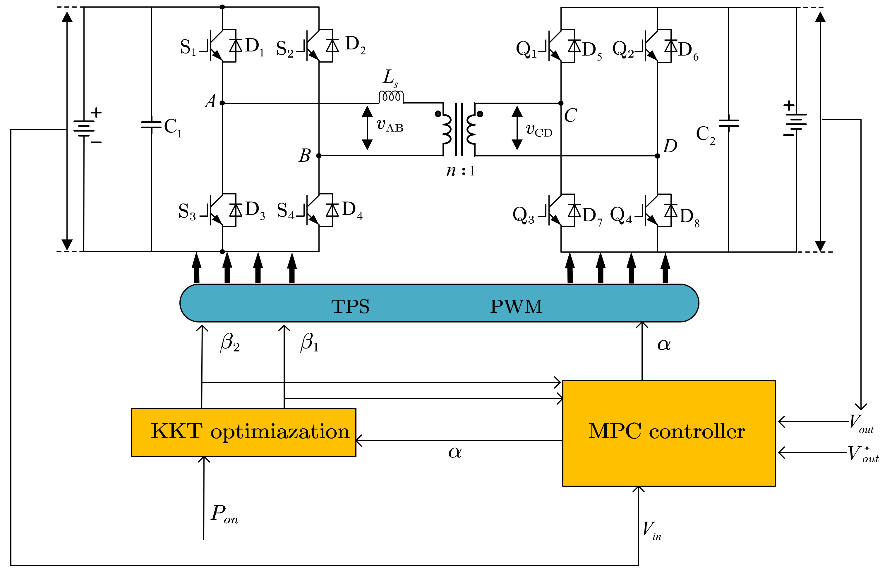
94]. When it comes to achieving rapid dynamic responses, MPC emerges as a highly promising alternative to traditional power converter control techniques. Additionally, the TPS method stands out as a particularly effective modulation strategy for DAB converters. This approach mitigates circulating current, reduces current-related stress, minimizes EMI noise, and extends the zero-voltage switching (ZVS) range, as visually represented in
Figure 11. Hence, in the existing literature, there has been the introduction of a TPS-based MPC approach as outlined in Reference [
95]. This method incorporates a current stress optimization scheme based on TPS modulation to elevate dynamic performance while adhering to the minimal current stress constraint, ensuring the maintenance of the desired output voltage level. A predictive model has been meticulously devised to accurately forecast the dynamic behavior of the output voltage in response to variations in input voltage and load disturbances. Notably, the model development is rooted in TPS modulation, facilitating the computation of the internal phase shift of the H-bridge through the current stress optimization TPS scheme. Results from both simulations and experimental tests provide compelling evidence for the merits of this proposed control algorithm, characterized by rapid dynamic response, absence of output voltage overshoot, consistent switching frequency, low computational complexity, and robust stability.
The input of the MPC controller is the sampled voltage of DAB at time
,
, and the reference voltage
. Using
as input, the future output voltage
at each future sampling time within the prediction horizon
is predicted, where
. The specific calculation formula is as follows:
As shown in Equation (30),
also depends on the future control input signal
. To accurately and quickly track the desired output voltage, the control input signal is calculated by minimizing a cost function:
Subject to constraints:
The control objective is to compute the sequence of future control signals , , …, which makes the output voltage closest to the reference .
5.3. Model Reference Adaptive Control for DAB
Adaptive control theory is a powerful tool for controlling power electronic converters, which are used in a wide variety of applications ranging from renewable energy systems to electric vehicles [
86]. The goal of adaptive control theory is to design control algorithms that can adapt to changes in the converter’s operating conditions, such as changes in the load or input voltage. One of the key concepts in adaptive control theory is the use of adaptive algorithms to adjust the controller’s parameters in response to changes in the system’s behavior. These algorithms are typically based on a mathematical model of the converter, which describes the relationship between the input and output voltages, currents, and other key variables. The adaptive algorithm uses this model to estimate the converter’s parameters, such as the resistance and inductance of the load, and then uses this information to adjust the controller’s parameters to achieve the desired performance. There are many different types of adaptive algorithms that can be used in power electronic converters, including model reference adaptive control (MRAC), self-tuning regulators (STR), and adaptive sliding mode control (ASMC) [
86,
96,
97]. Each of these algorithms has its own strengths and weaknesses, and the choice of algorithm depends on the specific requirements of the application.
The advantages of adaptive control applied to DC-DC converters include improved performance in the presence of uncertainties, robustness to variations in the system parameters, and the ability to adapt to changes in the load and input voltage. However, adaptive control can be complex to implement, and the convergence of the adaptive algorithm may depend on the design of the adaptive law and the choice of the adaptation parameters.
References [
68,
97] proposed a control strategy for DAB converters based on the traditional MRAC with SPS modulation strategy. However, high-frequency oscillations are inevitable when choosing large adaptive gains to accelerate asymptotic tracking, as traditional MRAC only guarantees the asymptotic stability of the system without considering its dynamic performance. In pursuit of enhancing the dynamic performance of the DAB converter, Reference [
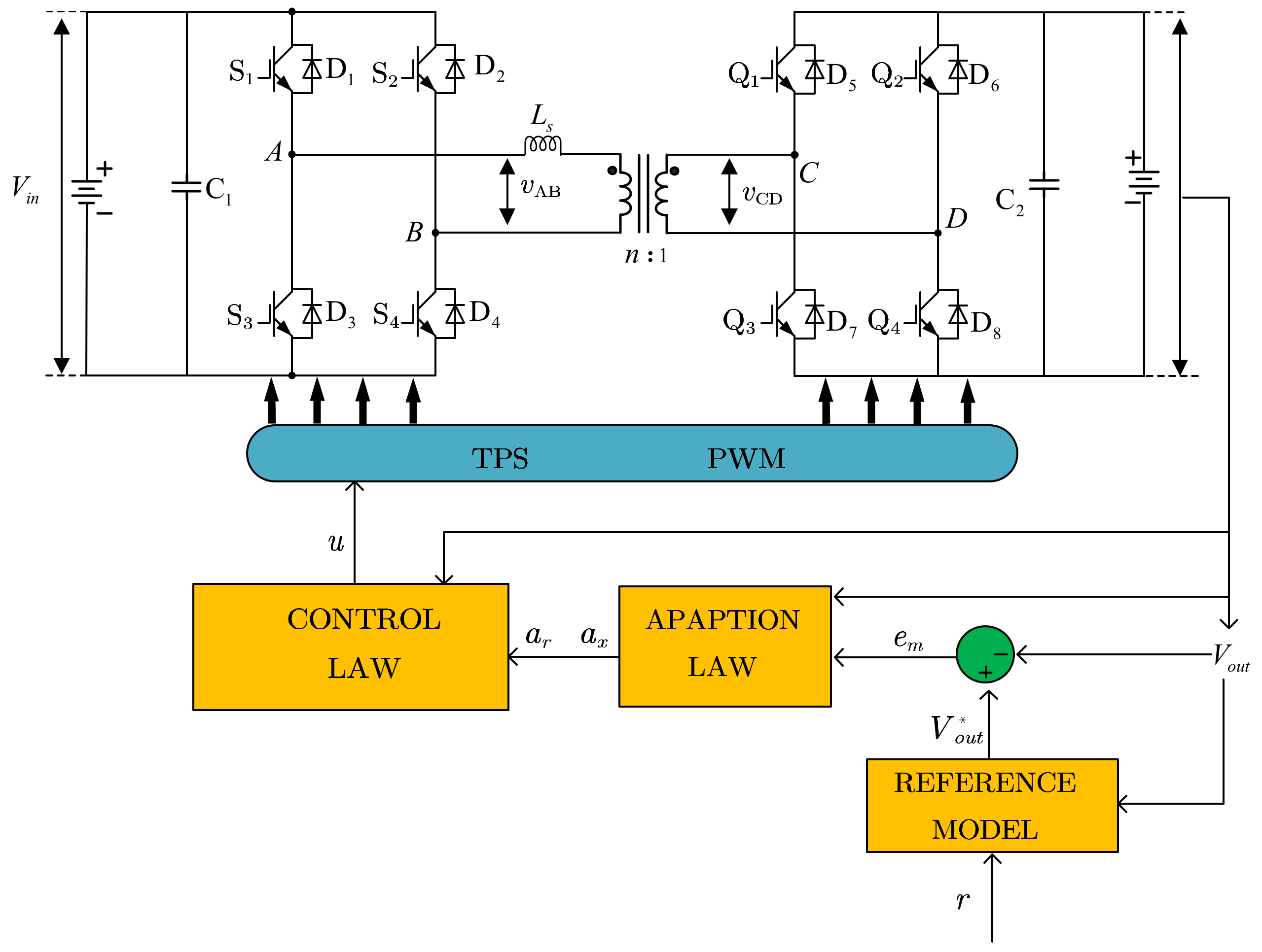
69] introduces an upgraded model reference adaptive control (MRAC) strategy founded on TPS modulation. This strategy enhances the system’s tracking capability and bolsters its dynamic response by introducing tracking errors into the reference model within the MRAC framework. Moreover, to comprehensively assess the influence of multidimensional modulation schemes on the MRAC model, a generalized averaging model (GAM) is established using the TPS modulation scheme as its basis, building upon the foundation of the uniform-phase-shift (UPS) modulation scheme. Ultimately, the efficacy of this proposed approach is confirmed through simulation experiments. The control method is shown in
Figure 12.
The reference model for DAB converters is formally established as follows:
where
,
, and
are considered positive. Then, the control law is obtained in the form of state feedback in Equation (34).
The adaptive rule governing the defined parameters is as follows:
where
and
is considered positive.
The error system of IMRAC is:
The Lyapunov energy function is defined as:
It can be demonstrated through a straightforward derivation that the Lyapunov energy function exhibits negative definiteness.
5.4. Active Disturbance Rejection Control for DAB
The main idea of Active Disturbance Rejection Control (ADRC) is to define an extended state variable, which includes both internal and external disturbances, and then use an extended state observer (ESO) to observe the total disturbance of the system and compensate for it in the controller. The input and output of the system are simplified to be transformed only by a pure integrator and can then be controlled by a PD controller [
98,
99].
The biggest advantage of ADRC is that it does not require an exact mathematical model of the controlled system, which gives it an engineering practicality that other intelligent control methods may lack. For the most practical engineering systems, it is difficult to establish an accurate mathematical model, and the system parameters may change with operating conditions, requiring the controller to have good robustness. The ADRC has received widespread attention in recent years because of its good robustness, low requirement for system models, and better dynamic performance compared with PI control. However, the ADRC method may require high computational resources for real-time implementation, and the design of the nonlinear state observer and the controller can be challenging.
References [
100,
101] applied the ADRC method to DAB dynamic control, and [
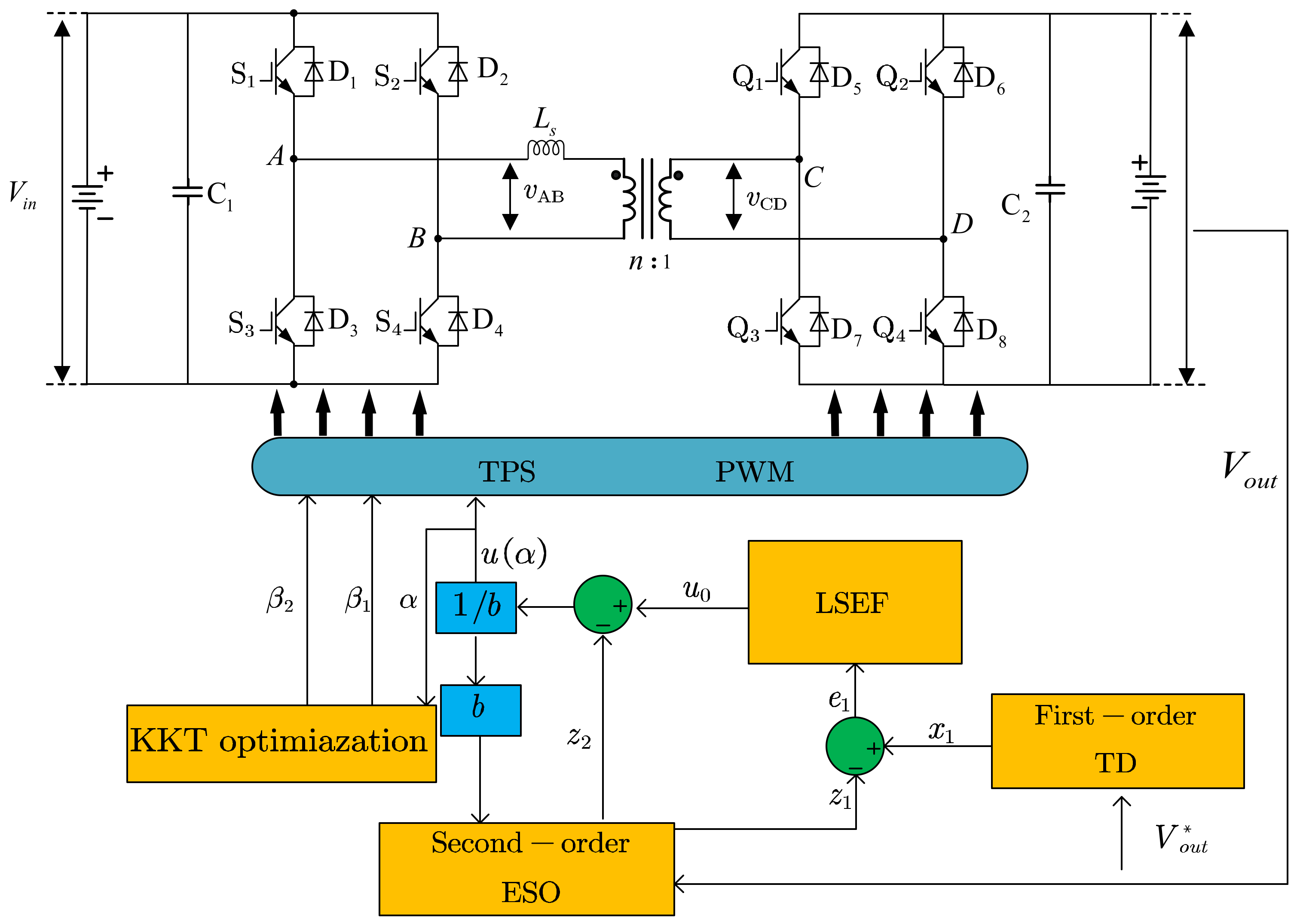
102] proposed an artificial neural network-based ADRC to regulate constant output voltage quickly and accurately under different operating conditions. Reference [
103] used a particle swarm optimization algorithm to tune the parameters of the ADRC. Currently, the design of ADRC for DAB is based on the reduced-order modeling method to establish a first-order equivalent model of the DAB, and then design a second-order ESO. The specific control method is shown in
Figure 13.
To design a first-order active disturbance rejection controller (ADRC), a first-order model of the system is established. Based on the reduced small-signal model of the DAB converter in
Section 3.1, the time-domain expression of the DAB converter can be derived.
The expression in Equation (40) in a general form is as follows:
The control objective is to maintain a stable output voltage, with the control variable being the phase-shift ratio
. The output
represents the output voltage of the converter, while the controller output
represents the phase-shift ratio
. The variable
represents disturbances within and outside the system, while
is an internal parameter of the DAB converter that is unknown, as well as
. The input control gain
is partially known, with the known part denoted as
, where
. Therefore, the equation can be written as:
Equation (42) considers the uncertainties in the internal parameters of the system as well as the external disturbances. Although the inductance parameter ls is included in b0, the effect of inductance can be neglected due to the compensating action of the total disturbance.
By selecting the state variables
, the state vector
includes both the system state variables and the total disturbance. Let
, then the system state equation can be obtained as follows:
For a first-order system, it is not necessary to observe the differential signals of the system state variables. Therefore, the first-order linear error state feedback law can be expressed as:
where the term
represents the output of LSEF and
represents the gain of the proportional controller.
Traditional PI controllers can eliminate system errors through integration, but they may also reduce system stability. The first-order LADRC can use second-order LESO to compensate for generalized disturbances in real time, effectively avoiding the negative impacts caused by integration. By estimating the total disturbance of the system using expanded state variables and compensating for the input end of the system, the control system can achieve better performance.
5.5. Comparison of Different Dynamic Control Methods
GVFC is a popular control method based on the Proportional–Integral (PI) control strategy. It offers a straightforward and easily implementable approach, delivering satisfactory steady-state performance under stable operating conditions. However, its effectiveness is limited when confronted with nonlinearities and uncertainties, leading to inadequate dynamic response, especially in scenarios characterized by rapidly changing operating conditions. Consequently, it is not suitable for applications demanding precise performance under varying operating conditions.
MPC exhibits favorable tracking performance and disturbance rejection capabilities for DAB in various operating modes. Since DAB converters can establish accurate mathematical models, MPC can effectively handle nonlinearities and uncertainties. However, MPC’s computational complexity and resource requirements are significant, necessitating powerful hardware support. Additionally, if the operating environment of the DAB converter system undergoes changes, it may lead to model variations that undermine the effectiveness of model predictive control.
In comparison to the aforementioned methods, MRAC overcomes its limitations by adapting to system uncertainties, variations, and nonlinearities without relying on precise system models. It can deliver good tracking and disturbance rejection capabilities under dynamically changing operating conditions. However, its implementation may be complex, requiring extensive system identification and parameter estimation processes.
ADRC exhibits resilience against disturbances and uncertainties. It effectively handles nonlinearities and time-varying dynamics without relying on precise system models, ensuring satisfactory tracking performance and disturbance rejection. However, the design of its core component, the ESO, is challenging, as poor design choices can hinder effective tracking of state variables and subsequently impact control performance.
In conclusion, while the generalized voltage feedback control is a simple and widely used strategy with good steady-state performance under stable operating conditions, it is limited in handling nonlinearities and uncertainties, making it unsuitable for applications with stringent performance requirements or varying operating conditions. MPC provides good tracking and disturbance rejection capabilities for DAB in different operating modes, but its implementation complexity and reliance on accurate system models may pose challenges. MRAC and ADRC offer solutions to these limitations, adapting to uncertainties, variations, and nonlinearities without requiring precise system models. However, they may involve complex implementation procedures and design considerations.
6. Conclusions
This passage presents a comprehensive review of various aspects concerning the research on DAB, encompassing modulation strategies, optimization algorithms, modeling methods, and advanced control techniques. The findings of DAB research are summarized as follows:
Two categories of modulation strategies are comprehensively introduced: PSM strategy and ADM strategy. The PSM strategy encompasses SPS, DPS, EPS, and TPS modulation methods, albeit essentially summarized by the TPS modulation method. The ADM strategy further extends the PSM strategy by introducing control over the conduction time of the same bridge arm switches. Continuing with the analysis, a comparative evaluation of various modulation methods’ complexities and flexibilities was conducted, alongside a simulation-based comparison of the power characteristics of these methods. Recently, scholars have proposed ADM strategies, which offer greater flexibility compared with traditional PSM techniques. ADM modulation has emerged as one of the recent focal points in DAB research.
The commonly employed modeling methods for DAB were reviewed, including reduced-order modeling, generalized state-space averaging modeling, discrete-time modeling, and Fourier series-based universal modeling. Each modeling method is applicable to different scenarios and with varying levels of precision. Reduced-order modeling is widely adopted due to its simplicity and broad applicability. Generalized state-space averaging modeling offers higher modeling accuracy while simplifying circuit state analysis by reducing the required variables and equations. However, its modeling accuracy is compromised by neglect of higher-order harmonics in practical applications, and its complex theoretical foundation lacks the clear physical concepts found in reduced-order modeling. Discrete-time modeling is primarily used to incorporate high-frequency dynamics, particularly in advanced control methods. Fourier series-based universal modeling presents a comprehensive approach to establishing DAB operation models under various modulations, streamlining the analysis process at the expense of increased computational complexity. The diverse optimization algorithms are subsequently presented, including the KKT approach, GA, PSO, and Q-learning algorithm. The KKT approach is suitable for simple modulation techniques but not well-suited for multi-objective optimization. The GA exhibits moderate performance across different modulation techniques. The PSO algorithm demonstrates excellent environmental adaptability but may suffer from premature convergence. Combining PSO with other algorithms such as GA or KKT can address this issue. The Q-learning algorithm, when combined with artificial neural networks, exhibits robust environmental adaptivity and capability to achieve online continuous optimization, making it a promising approach.
The advanced dynamic control methods for DAB are reviewed: GVFC, MPC, MRAC, and ADRC. When GVFC is straightforward, it has limitations in handling non-linearity and uncertainties. MPC offers good performance but requires powerful hardware and accurate DAB models. MRAC and Active ADRC adapt to uncertainties without relying on DAB models, albeit posing challenges in implementation and design due to their complexity.
With the introduction of advanced modulation strategies, the modeling and control methods of DAB face new challenges. Despite some existing literature that combines advanced control methods with advanced optimization modulation methods, such studies remain relatively scarce, and some control methods have yet to incorporate advanced modulation strategies. Moreover, most articles simplify DAB to a first-order model for controller design, which compromises the controller’s performance under significant disturbances. Furthermore, the advanced control methods are predominantly investigated under the framework of phase-shift modulation strategies, lacking research inegration with asymmetric PWM strategies, which represents a notable research gap.


