Article

Economic Analysis of Li-Ion Battery–Supercapacitor Hybrid Energy Storage System Considering Multitype Frequency Response Benefits in Power Systems

1
Power China Huadong Engineering Corporation Limited, Hangzhou 310000, China
2
College of Electrical Engineering, Zhejiang University, Hangzhou 310027, China
*
Author to whom correspondence should be addressed.
Energies 2023, 16(18), 6621; https://doi.org/10.3390/en16186621
Submission received: 15 August 2023 / Revised: 8 September 2023 / Accepted: 12 September 2023 / Published: 14 September 2023
(This article belongs to the Section F1: Electrical Power System)

Abstract

:
With the promotion of carbon peaking and carbon neutrality goals and the construction of renewable-dominated electric power systems, renewable energy will become the main power source of power systems in China. Therefore, ensuring frequency stability and system security will emerge as pivotal challenges in the future development process. Created by combining a Li-ion battery and a supercapacitor, a hybrid energy storage system (HESS), which possesses robust power regulation capabilities and rapid response capabilities, holds promise for supporting the frequency stability of power systems. In this context, the assessment of the economic viability of HESSs providing multitype frequency response services becomes a critical factor in their deployment and promotion. In this paper, an economic analysis approach for a Li-ion battery–supercapacitor HESS towards a multitype frequency response is presented. First, a multitype frequency response-oriented operational mode for the HESS is designed, outlining the roles and functions of the Li-ion battery and the supercapacitor in delivering distinct services. Moreover, building upon the analysis of the power trajectory of Li-ion batteries, a lifetime model for the HESS is proposed based on the rain-flow counting method. Furthermore, considering the competitive landscape for the HESS in the frequency regulation ancillary service market, a full lifecycle economic assessment model is proposed. Finally, case studies on actual power system frequency data and PJM market data are performed to verify the effectiveness of the proposed method, and the simulation results confirm that the HESS exhibits robust performance and a competitive advantage in providing multitype frequency response services. Additionally, it demonstrates commendable economic benefits, establishing its potential as a valuable contributor to frequency response services.

Graphical Abstract

1. Introduction

With China clearly proposing the goal of “striving to achieve carbon peak before 2030 and carbon neutrality before 2060,” the energy sector, which has the highest proportion of carbon emissions, will undergo a fundamental reform with a high proportion of renewable energy sources replacing traditional fossil fuels [1,2]. Meanwhile, with the large-scale integration of power electronic devices into the power system and the deployment of high-capacity cross-regional direct current transmission technology, a high proportion of electrification through power electronics has also become a significant characteristic of the advanced power system [3]. In this context, the intermittency, randomness, and volatility of high-proportion renewable energy generation have posed significant challenges to the real-time balance of power supply and demand. Because synchronous generators are gradually being replaced, the pressure for frequency regulation has increased, leading to a reduction in the rotational inertia of the power system and an increasingly prominent issue of system frequency stability [4]. As the installed capacity of renewable energy generation continues to increase, existing frequency regulation methods may encounter bottlenecks, and the capacity for flexibility is gradually depleted. Therefore, there is an urgent need for further development and exploration of flexible regulatory resources, which can adjust the active power and promote the frequency restoration of power systems [5].
Energy storage, as an emerging power technology, not only enables the decoupling of electricity generation and utilization in time and space but also possesses strong power output and regulation capabilities [6,7]. With the maturation of energy storage technology and its business models, the manufacturing cost of energy storage has been significantly reduced, and the profits obtained from energy storage have increased [8]. Energy storage systems (ESSs), represented by electrochemical energy storage technology, have been widely deployed and applied on a large scale in the power system, providing a vast amount of flexible capacity and frequency support capabilities [9]. Currently, the Li-ion battery ESS is the most widely used and has the highest installed capacity among advanced energy storage technologies, and its functionality and effects in the field of frequency support have also garnered extensive attention and research [10,11].
Linear and understandable rules of frequency stability are proposed for unit commitment problems where the influence of the battery ESS is deeply considered [12]. In [13], using the isolated power system of Israel as an example, the frequency regulation effect of a 30 MW battery ESS is quantified, suggesting that battery ESSs can provide significant dynamic operational benefits for power companies. In [14], a pre-hour optimal bidding strategy is proposed for shared battery ESSs targeting energy and power ancillary service markets, enabling shared energy storage in order to simultaneously provide primary and secondary frequency regulation (SFR) services. In [15], which focuses on primary frequency regulation (PFR), the impact of different state-of-charge (SOC) management strategies on the lifetime of a Li-ion battery ESS is analyzed. However, although Li-ion battery energy storage boasts high energy density, adaptability to various scenarios, and a fast construction speed, it still faces challenges such as a relatively short cycle life and an inability to respond instantaneously. As a result, the capability of Li-ion battery ESSs to provide an inertial response for the power system is relatively weak, and their lifetime also affects the economic viability of energy storage investments [10].
Supercapacitors represent another type of power-oriented energy storage technology, characterized by long cycle life, extremely fast response speed, and high charge–discharge efficiency. In [16], a supercapacitor is introduced to provide the transient power required by electromechanical actuators on-board aircraft. In interconnected PV-based AC microgrid clusters, the supercapacitor can be adopted to improve the dynamic inertia response [17]. In [18], an inertia emulator formed with supercapacitors is proposed to improve inertia in a low-inertia grid considering the influence of high-proportion renewable energy generation. However, supercapacitors have a low energy density and cannot support prolonged charge–discharge periods. Due to the complementary characteristics of supercapacitors and Li-ion batteries, the two can be combined into a hybrid energy storage system (HESS) to compensate for the drawbacks of standalone ESSs [19]. In [20], the applications of HESSs in microgrids are reviewed comprehensively, in cases where HESSs have been adopted to improve power quality, provide ancillary services, and contribute in terms of frequency. The combined battery ESS and supercapacitor can grip average and transient power changes to stabilize the power system [21]. A HESS consisting of a battery and a supercapacitor is proposed in [22] to achieve the power management of virtual synchronous generators, and the proposed HESS can exhibit a similar frequency dynamic response to those of synchronous generators. In [23], a Li-ion battery–supercapacitor HESS is used to provide an inertial response and PFR services, with the supercapacitor component enhancing the system’s inertia. In [24], the concept of frequency-coordinated virtual impedance is proposed for autonomous control of DC microgrids. This control strategy enables effective power frequency allocation between Li-ion batteries and supercapacitors, achieving seamless transitions. In [25], power imbalances caused by renewable energy generation are categorized into small, medium, and large power fluctuations, compensated for and smoothed by Li-ion battery energy storage, supercapacitors, and conventional generators, respectively, which achieve high-precision, fast-response SFR. At present, the feasibility of a HESS providing services like inertial response, PFR, and SFR has already been verified. However, there is limited research on the economic assessment of HESSs participating in diverse frequency response services. It is important to note that the economic evaluation of HESSs needs to be considered within specific broader contexts. Taking China as an example, with the gradual development of and improvements in the electricity market, the impact of market-driven frequency response services on HESSs needs to be carefully considered [26].
This paper focuses on the economic analysis of a Li-ion battery–supercapacitor HESS for multitype frequency response services, aiming to provide reference information for energy storage investment and capacity configuration decisions. The main contributions of this paper are as follows:
(1)
An operational mode for a HESS tailored to multitype frequency response is developed, and the operational paradigm of the HESS for different frequency response services is determined.
(2)
A lifetime model for the HESS considering multitype frequency response is designed based on the rain-flow counting method, which introduces a frequency regulation mileage-energy storage power mapping scheme based on the Monte Carlo simulation.
(3)
A frequency regulation ancillary service market-clearing model that accounts for the participation of the HESS is proposed, and a comprehensive lifecycle economic evaluation model for the HESS is presented.

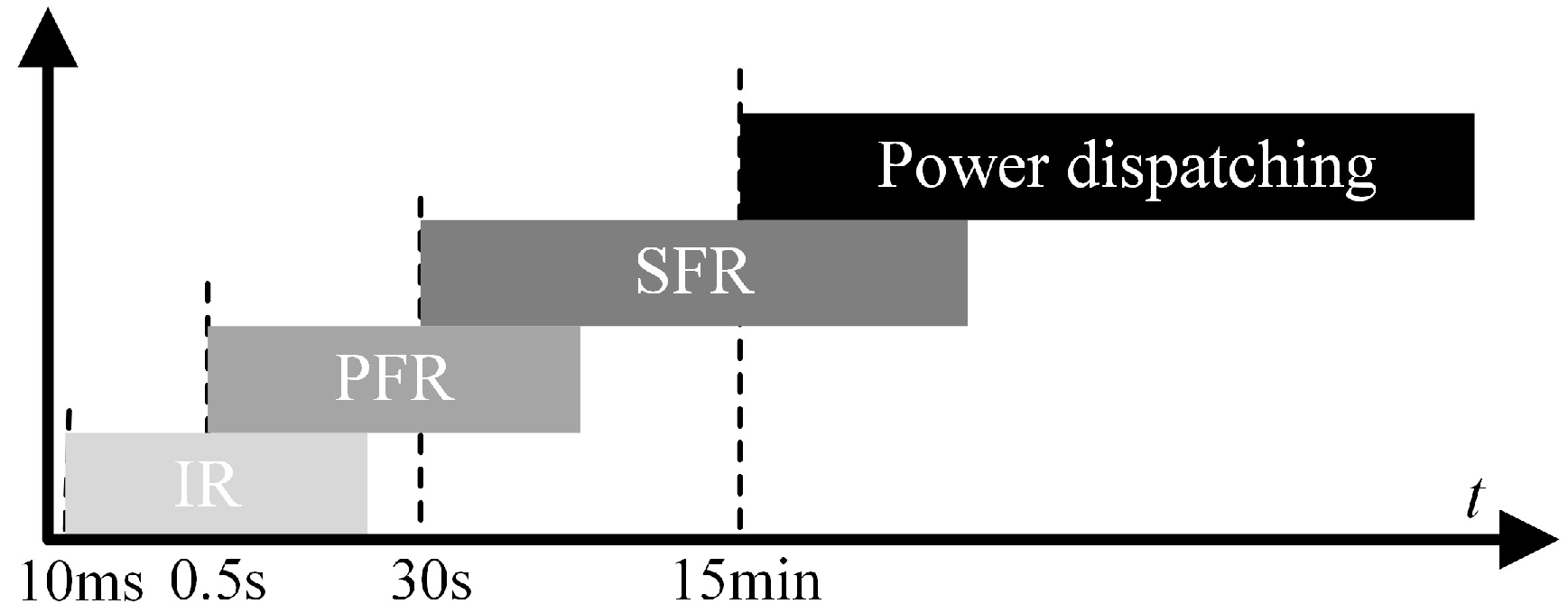
2. HESS and Its Frequency Response Mode

2.1. Li-ion Battery–Supercapacitor HESS

Li-ion batteries are common energy storage components that are widely utilized in power systems. However, during their practical operation, Li-ion battery ESSs exhibit a delay in responding to disturbances within the power system, requiring a certain response time (although the delay is typically just a few hundred milliseconds). As the amount of renewable energy generation continues to rise, the rotational inertia of power systems gradually decreases. Therefore, there is a growing need for novel types of power equipment to serve as new sources of rotational inertia, resulting in higher requirements for the inertia support capabilities of ESSs in the future. Furthermore, while the cycle life of Li-ion batteries has significantly improved in recent years, further extension of the lifetime of Li-ion battery ESSs remains a key factor in enhancing investment benefits.
To simultaneously meet the performance requirements of providing multitype frequency response capabilities, combining Li-ion batteries with supercapacitors to create a HESS becomes a reasonable choice. In the HESS, Li-ion batteries are used as energy reservoirs due to their high energy density, while supercapacitors, with their high power density and rapid charge–discharge characteristics, serve as power reservoirs. By integrating these two components, it becomes possible to leverage the high-energy-density advantages of Li-ion batteries to ensure sufficient discharge durations for SFR. Simultaneously, the characteristics of supercapacitors are utilized to actively manage short-term, high-power signals, meeting the demands for inertial response while effectively protecting Li-ion batteries and significantly extending their lifetime.

2.2. Operational Mode of HESS for Multitype Frequency Response

As shown in Figure 1, following a disturbance in the power system, its active frequency dynamic process goes through inertia response and frequency regulation stages, bringing the power system back to equilibrium. During this process, the HESS can provide corresponding frequency support services to the power system at different stages through control strategies.

2.2.1. Inertia Response Mode of HESS

Considering the power system’s high requirements for inertia response speed, the task of inertia response is undertaken by the supercapacitors. Although supercapacitors provide physical energy storage, they lack the same physical inertia as synchronous generators. In this scenario, virtual synchronous machine technology can be employed to impart inertia attributes to the supercapacitors.
The principle of a virtual synchronous machine involves introducing the synchronous machine’s rotor motion and electromagnetic transient equations into the inverter control loop, giving it the external characteristics of synchronous machine operation and simulating the synchronous machine’s voltage source characteristics [22,27]. Supercapacitors based on virtual synchronous machine technology exhibit the same external characteristics as synchronous machines. Their inverter output voltage is the controlled variable, and the output power is the manipulated variable, allowing for disturbance power distribution similar to that of synchronous generators. When a power disturbance occurs, the output power of the inverter experiences abrupt changes, resulting in an imbalance between the input and output power of the unit. The inertia energy storage unit immediately absorbs or releases energy in response to the input–output power deviation, supporting the output power to maintain the power balance within the system. Its inertia response characteristics are similar to those of synchronous machines, enabling instantaneous provision of inertia support power during moments of unbalanced power without delay. Supercapacitors controlled by a virtual synchronous machine equivalent effectively increase the system’s inertia level, slowing down the rate of frequency change during disturbances.
Since only supercapacitors are involved in the inertia response, the inertia response power at this point is equivalent to the power of the supercapacitors.

2.2.2. PFR Mode of HESS

When the frequency of the power system exceeds the regulation deadband, Li-ion batteries adjust their active power output through a rapid frequency response to reduce frequency deviations. In general, Li-ion batteries can participate in PFR using either virtual inertia control or virtual droop control. The former can quickly support the system frequency, while the latter can effectively reduce frequency variation. Compared with supercapacitors using virtual synchronous machine technology, not only do Li-ion batteries involved in PFR have a longer response time, but virtual inertia control also introduces a certain delay (around 100 ms). This is because virtual inertia control requires measuring the system frequency, filtering it, and feeding it back to the active power control loop of the inverter to change the active power reference value.
For thermal power generation units, inertia response involves supplementing or absorbing unbalanced power in the system through inertia-supported power from energy storage components like rotors. On the other hand, PFR entails increasing or decreasing power from the prime mover to compensate for the unbalanced power caused by disturbances. However, for ESSs, inertia response, PFR, and subsequent SFR all involve energy storage or release. Therefore, after providing instant inertia support power, supercapacitors’ subsequent power output and variations can be considered as PFR. In this case, the PFR power of the HESS is the sum of the powers of the supercapacitors and Li-ion batteries. It is worth noting that the duration of PFR typically does not exceed 30 s. To ensure consistency between the availability of PFR in the HESS and the declared parameters, supercapacitors should be configured based on a standard duration of no less than 30 s.

2.2.3. SFR Mode of HESS

During the process of SFR, the HESS needs to track the commands issued by the power dispatch agency and adjust the power generation and consumption in real time at a certain rate to meet the requirements of power system frequency and interconnection power control. Compared with the inertia response, SFR has lower requirements for response time but has certain duration requirements. Considering the relatively high cost of increasing the capacity of supercapacitors, SFR is primarily carried out by Li-ion batteries. In this case, the SFR power of the HESS is the power of the Li-ion batteries.
It is worth mentioning that the cycle life of supercapacitors far exceeds that of Li-ion batteries. Therefore, supercapacitors can track the peak portion of the frequency regulation signal during the SFR process, reducing the number of charge–discharge cycles of Li-ion batteries and extending their lifetime.

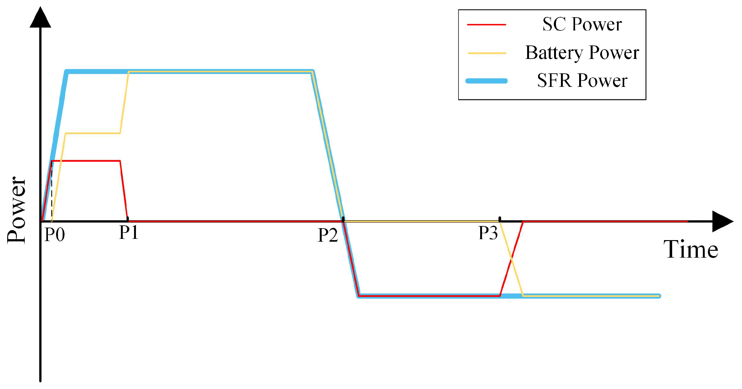
3. HESS Lifetime Model Considering Multitype Frequency Response

In the process of providing multitype frequency response services, the HESS undergoes charging and discharging cycles of both Li-ion batteries and supercapacitors, leading to a reduction in the lifetime of the HESS. Constructing a lifetime model for the HESS that considers multitype frequency response is essential for providing crucial lifetime information for economic analysis.
As the cycle life of supercapacitors is influenced by factors such as temperature, discharge rate, and current waveform, with no definite conclusion on the extent of these influences [28], and since their cycle life is as high as 500,000 to 1,000,000 cycles [29], significantly exceeding that of Li-ion batteries, this paper assumes that the lifetime of supercapacitors is notably longer than that of Li-ion batteries. Therefore, the lifetime of the HESS is determined by the lifetime of the Li-ion batteries.

3.1. Li-ion Battery Power Trajectory for Multitype Frequency Response

The lifetime of a Li-ion battery is closely related to its operational mode, with a shorter cycle life associated with deeper discharge depths. Therefore, by designing a power model for Li-ion batteries tailored to multitype frequency response, the operational modes of Li-ion batteries during primary and SFR processes can be described, laying the foundation for constructing the lifetime model.
When a Li-ion battery participates in PFR using virtual droop control, its active power increment can be expressed as follows:
Δ P LB = K PFR ( f PS f DZ )
where Δ P LB denotes the active power increment of the Li-ion battery participating in PFR. f PS and f DZ respectively denote the real-time frequency of the power system and the deadband frequency of PFR. K PFR denotes the droop coefficient, where a larger value indicates that, under the same frequency deviation, the Li-ion battery output is larger. Based on Equation (1), the HESS continuously measures the frequency value of the power system. When the measured frequency exceeds the deadband value, the Li-ion battery changes its output to reduce the system frequency deviation. In this scenario, based on the historical frequency data of the power system, the power trajectory of the Li-ion battery for PFR can be characterized within that power system environment, thereby obtaining the state of lifetime degradation for the Li-ion battery.
Unlike PFR, the HESS participates in SFR by tracking the frequency regulation commands issued by the power dispatch authority. In this context, as illustrated in Figure 2, the sum of the absolute values of upward and downward adjustments of output power based on frequency regulation commands within a certain time interval is referred to as the frequency regulation mileage. The frequency regulation mileage is a key indicator for compensating SFR services. A larger frequency regulation mileage indicates a greater contribution of frequency regulation resources to the power system’s SFR. With the maturation of the frequency regulation ancillary service market, the average frequency regulation mileage is often disclosed as public data to all market users. Hence, the power trajectory of the HESS participating in SFR can be characterized based on historical data on frequency regulation mileage. Considering that the frequency regulation mileage reflects a comprehensive profile of power changes over a specific period, it needs to be mapped to corresponding power trajectories. Assuming that the power adjustments are uniformly distributed within the frequency regulation capacity range, the Monte Carlo simulation can be used to generate corresponding power trajectory changes. Simultaneously, the sum of the absolute values of changes in power trajectories must be equal to the frequency regulation mileage for that time period.
It is worth noting that, in order to enhance the lifetime of the Li-ion battery, the supercapacitor is prioritized for charging or discharging when it has regulation capabilities, as depicted in Figure 3. From point P0 to point P1, the supercapacitor has capacity and space for upward regulation, so it discharges at maximum power. At this point, the power of the Li-ion battery is the frequency regulation command power minus the supercapacitor power. It is worth noting that the supercapacitor first increases the power after receiving the signals of the frequency regulation command power. Once the frequency regulation command power is larger than the rated power of the supercapacitor, the Li-ion battery also increases the power to meet the demand of the command power. From point P1 to point P2, due to insufficient stored energy, the supercapacitor cannot continue to discharge, so the power is reduced to zero, and the Li-ion battery increases power to compensate for the decrease in supercapacitor power. From point P2 to point P3, the supercapacitor has capacity and space for downward regulation, so it charges at maximum power, while the power of the Li-ion battery is zero. When the supercapacitor no longer has a charging capacity, the Li-ion battery enters the charging state and provides downward regulation power.

3.2. HESS Lifetime Model Based on Rain-Flow Counting Method

The rain-flow counting method, also known as the “tower top method,” is widely used in engineering, especially in fatigue life calculations [30]. Therefore, by utilizing the rain-flow counting method to calculate the depth of discharge for the battery, and then establishing the corresponding relationship between battery discharge depth and cycle life, the equivalent cycle life of the battery can be determined. It should be noted that a complete cycle consists of a discharge half-cycle and a charge half-cycle, as illustrated in Figure 4. In Figure 4, there are two complete cycles (B-C-B’ and E-F-E’) and two half-cycles (A-B-B’-D and D-E-E’-F).
The cycle life of a Li-ion battery is influenced by various factors, such as temperature, peak current, and the number of charge–discharge cycles. For simplification, only the effects of the number of charge–discharge cycles and discharge depth on the battery cycle life are considered.
The discharge depth of the h-th cycle period of the Li-ion battery is defined as D h D . Therefore, the equivalent cycle life is given by
N h ECL = N CL ( 1 ) N CL ( D h D )
where N h ECL denotes the equivalent cycle life of the Li-ion battery for the h-th cycle period. N CL ( 1 ) and N CL ( D h D ) respectively denote the cycle life of the Li-ion battery with discharge depths of 1 and D h D .
In this case, the equivalent cycle life N ECL of the Li-ion battery over an operational period is given by
N ECL = h = 1 H L N h ECL
where H L denotes the total number of cycle periods. When N ECL = N CL ( 1 ) , the Li-ion battery’s lifetime is considered to be exhausted, and the battery pack needs replacement. The year corresponding to the H L -th cycle period is the operational year of the HESS.

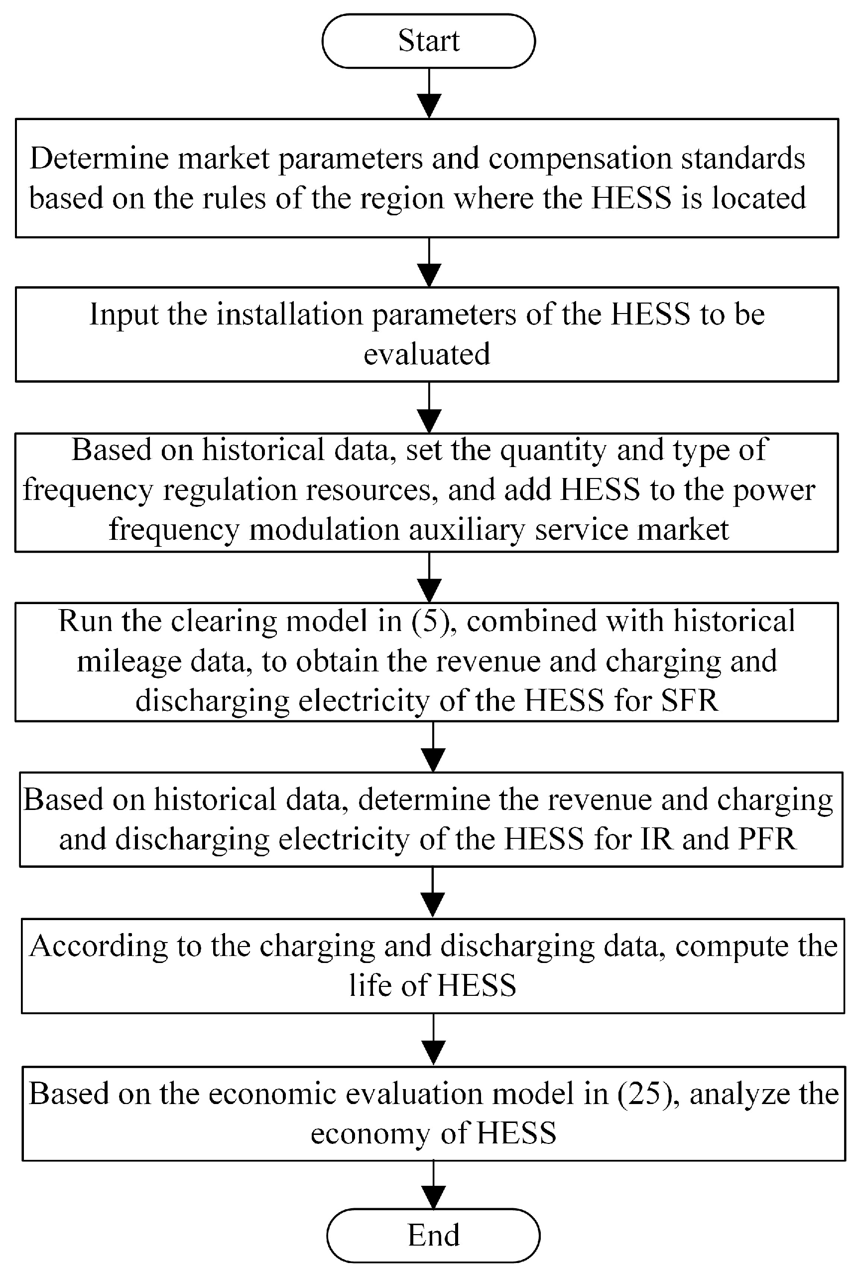
4. Economic Assessment Model for HESSs Considering Frequency Regulation Market Mechanism

In many countries, such as China, compensation and payment for frequency response-related ancillary services such as inertia response, PFR, and SFR have been stipulated. At present, a market-oriented mechanism for SFR services has been preliminarily established in China, with pilot programs for frequency regulation ancillary service markets being conducted in regions such as Shanxi, Fujian, and Chongqing. This aims to optimize and improve the allocation of resources for SFR. As for inertia response and PFR, a planned compensation approach is still predominantly employed in China. Under this approach, resources providing the respective services are compensated based on their service effectiveness. In this context, for HESSs capable of offering multitype frequency response services, their overall lifecycle economic viability should fully consider the market-driven revenue and nonmarket compensation resulting from different frequency regulation response services [31].
Firstly, based on the typical market mechanism for SFR services, a frequency regulation market-clearing model is constructed to simulate the operational status of HESSs in typical SFR scenarios. Subsequently, building upon the foundation of SFR services, the potential reuse of functionalities in inertia response and PFR by HESSs is considered. This results in the development of a profit model tailored for multitype frequency response services with HESSs. Lastly, the overall lifecycle costs associated with providing multitype frequency response services with HESSs are taken into account. The designed lifecycle economic assessment model integrates the HESS’s lifetime model to achieve a comprehensive cost–benefit analysis of the HESS.

4.1. Frequency Regulation Ancillary Service Market-Clearing Model Considering HESSs

4.1.1. Objective Function

In the rules governing frequency regulation ancillary services, the power dispatch agency aims to minimize the frequency regulation cost when clearing frequency regulation resources. It seeks to procure frequency regulation resources with good regulation performance and low pricing, thereby minimizing the overall frequency regulation cost of the entire power system while meeting the market’s frequency regulation demand. Consequently, the frequency regulation ancillary service market-clearing model adopts the minimization of frequency regulation costs as its objective function, which can be expressed as
min E FR = t = 1 T i = 1 I δ i , t P i , t R ( C i , t π t C η i + M i , t π t M )
where E FR denotes the frequency regulation cost of the power system. δ i , t is a binary variable, denoting the operating state of frequency regulation resource i in time period t . P i , t R denotes the actual performance metric of frequency regulation resource i in time period t . C i , t denotes the awarded capacity of frequency regulation resource i in SFR in time period t . η i denotes the capacity efficiency of the frequency regulation resource i . M i , t denotes the frequency regulation mileage of the frequency regulation resource i in time period t . π t C and π t M denote the capacity price and mileage price of the time period t , respectively, both of which are unified market-clearing prices. T denotes the number of dispatching periods, and I denotes the number of frequency regulation resources.
From Equation (4), it can be observed that the frequency regulation cost of the power system refers to the frequency compensation obtained by the frequency regulation resources providing the services. This cost is primarily influenced by the performance metrics, awarded capacity, and frequency regulation mileage of the frequency regulation resources.
The performance metrics of frequency regulation resources quantitatively measure the differences in key frequency regulation performance aspects such as regulation accuracy, response time, and adjustment speed among different resources. On one hand, this allows the power system to procure high-quality frequency regulation resources at a relatively low price. On the other hand, it enables well-performing resources to be utilized more fully and benefit more, thus optimizing the allocation of frequency regulation resources. Therefore, the performance metrics of frequency regulation resources can be expressed as follows:
P i , t R = λ AA K i , t AA + λ RT K i , t RT + λ RS K i , t RS
where K i , t AA , K i , t RT , and K i , t RS denote the regulation accuracy score, response time score, and adjustment speed score of frequency regulation resource i in time period t , respectively. λ AA , λ RT , and λ RS are the corresponding weight coefficients. Among these, the regulation accuracy score K i , t AA is used to assess the disparity between the actual frequency regulation power and the frequency regulation signal, which can be expressed as follows:
K i , t AA = 1 1 J i , t j = 1 J i , t max { | O i , t , j R i , t , j | } R ¯ i
where R i , t , j denotes the j-th frequency regulation signal received by frequency regulation resource i in time period t , and O i , t , j signifies the power of the response of the frequency regulation resource to that signal. J i , t denotes the total number of frequency regulation signals received by the frequency regulation resource i in time period t . R ¯ i stands for the average absolute value of frequency regulation signals received by the frequency regulation resource in that time period. When K i , t AA is equal to 1, it indicates that the response power of the frequency regulation resource i is consistent with the frequency regulation signal. When K i , t AA is equal to 0, it signifies that the frequency regulation resource i is unresponsive to the frequency regulation signal.
Response time refers to the time taken by the frequency regulation resource to reliably cross the adjustment deadband in the same direction as the adjustment after the power dispatch agency issues a frequency regulation signal. Response time is typically measured by the time the frequency regulation resource spends within the adjustment deadband, which can be expressed as
K i , t RT = 1 J i , t j = 1 J i , t ( 1 T i , t , j 0 T i , t , j 1 ) ,     J i , t 1
where T i , t , j 0 and T i , t , j 1 respectively denote the deadband time of the adjustment process of frequency regulation resource i after receiving the j-th frequency regulation signal in time period t and the total duration from the reception to the completion of the j-th frequency regulation signal. The shorter the duration within the adjustment deadband, the better the response time performance, and the response time score K i , t RT will be closer to 1.
Adjustment speed refers to the rate at which the frequency regulation resource responds to the frequency regulation signal. It is measured by the ratio of the actual adjustment speed of each frequency regulation resource to the market-standard adjustment speed, which can be expressed as
K i , t RS = 1 J j = 1 J v i , t , j v B / max i I v i Ave v B
v B = i I σ i v i Ave
v i Ave = t = 1 T S j = 1 J i , t v i , t , j t = 1 T S J i , t
v i , t , j = | P i , t , j S P i , t , j E | T i , t , j S T i , t , j E
where v i , t , j denotes the actual adjustment speed of frequency regulation resource i in time period t when responding to the j-th frequency regulation signal. P i , t , j S and P i , t , j E respectively denote the actual power of the frequency regulation resource i at the onset and conclusion of the frequency regulation signal action, while T i , t , j S and T i , t , j E denote the start and end times of the response to the frequency regulation signal. v i Ave denotes the average adjustment speed of frequency regulation resource i within a certain period, and T S is the total number of time periods in the statistical cycle. σ i denotes the proportion of the installed capacity of frequency regulation resource i in the market.
Based on Equations (5)–(11), the frequency regulation resource performance metric P i , t R in time period t can be obtained based on the actual response performance of the frequency regulation resource i , serving as the basis for frequency regulation service settlement. On the other hand, by analyzing historical data on the frequency regulation resource over a certain period, the historical comprehensive frequency regulation resource performance metric P i RH , which is used for ranking resource quotations in the day-ahead market, can be obtained. In this case, P i , t R in Equation (4) is replaced by the estimated value P i RH during the clearing process. Similarly, the M i , t in Equation (4), which is an unknown variable during the clearing process, can be estimated using the historical frequency regulation mileage M i H of the frequency regulation resource.
In the clearing process of frequency regulation resources, both capacity bidding and mileage bidding need to take into account the past performance of resources in frequency regulation processes. Based on this, the original bids are adjusted, and the sum of the adjusted capacity bid and mileage bid is used as the basis for ranking resource dispatch and can be expressed as
π i R = π i AM + π i AC
π i AM = π i M / P i RH
π i AC = π i C / P i RH
where π i R denotes the comprehensive price of frequency regulation resource i . π i AM and π i AC denote the adjusted mileage bid and capacity bid, respectively. π i M and π i C denote the original mileage bid and capacity bid, respectively.
In summary, the objective function can be rewritten as
min E FR = t = 1 T i I δ i , t P i RH ( C i , t π t C η i + M i H π t M )
where δ i , t and C i , t are the decision variables of the frequency regulation ancillary service market-clearing model.

4.1.2. Constraint Conditions

The constraint conditions primarily include system frequency regulation capacity requirement and mileage requirement constraints, unit capacity, power and ramp rate constraints, SOC constraints of energy storage, and resource frequency regulation state constraints, namely
i I f i , t C i , t C t R
C i , t C i , t D
P i Gmin C i , t + P i , t G P i Gmax
μ i , t , j U + μ i , t , j D 1
θ i Min θ i , t Soc θ i Max , i I ESS
C i , t + P i , t G P i , t 1 G + C i , t 1 Δ P i
P i , t G P i , t 1 G C i , t C i , t 1 Δ P i
where C t R denotes the frequency regulation capacity requirement of the power system in time period t . f i , t denotes the utility factor of the frequency regulation resource i in time period t . C i , t D denotes the available frequency regulation capacity declared by the frequency regulation resource i in time period t . P i , t G denotes the power of the frequency regulation resource i in time period t in the electric energy market. P i Gmin and P i Gmax respectively denote the lower and upper limits of the power of the frequency regulation resource i . Both μ i , t , j U and μ i , t , j D are binary variables between 0 and 1, denoting whether the frequency regulation resource i is in an upward regulation state or a downward regulation state when responding to the j-th frequency regulation signal in time period t . θ i , t Soc denotes the SOC of the frequency regulation resource i in time period t . θ i Min and θ i Max respectively denote the upper and lower limits of the SOC of the frequency regulation resource i . I ESS denotes the set of energy storage-type frequency regulation resources. Δ P i denotes the ramping power of the frequency regulation resource i . It is worth mentioning that, compared with traditional frequency regulation resources such as thermal power units, the HESS has a faster adjustment speed, making it a type of fast frequency regulation resource. This work introduces the utility factor to measure the value of fast frequency regulation resources, which is the ratio of the required capacity of traditional frequency regulation resources to the capacity of fast frequency regulation resources when meeting the same frequency regulation requirements, and can be expressed as
f i , t = P i RH P ˜ RH
P ˜ RH = i I TU P i RH C i , t i I TU C i , t , i I TU
where P ˜ RH denotes the weighted average of performance metrics of all thermal power units in the power system. I TU denotes the set of thermal power units providing frequency regulation services.
In the multitype frequency response mode, the HESS autonomously engages in inertia response and PFR, thereby receiving economic compensation. By participating in the frequency regulation ancillary service market, it provides SFR services upon winning bids, thus gaining SFR benefits.

4.2. HESS Full Lifecycle Economic Assessment Model

In the full lifecycle economic assessment model of HESS proposed in this paper, various benefits such as inertia response benefits, PFR benefits, and SFR benefits are included, along with cost elements such as the initial investment cost, operational cost, and electricity loss cost of the HESS, which can be expressed as
R T = y = 0 Y ESS R y IR + R y PFR + R y SFR C y OM C y EL ( 1 + r ) y C Ini
where R T denotes the total lifecycle revenue of the HESS. R y IR , R y PFR , and R y SFR respectively denote the inertia response benefits, PFR benefits, and SFR benefits of the HESS in the y-th year. C y OM and C y EL denote the operational cost and electricity loss cost of the HESS in the y-th year. C Ini denotes the initial investment cost of the HESS. r denotes the discount rate.

4.2.1. Inertia Response Benefits

Currently, for inertia response services, compensation is typically based on their availability. Therefore, the inertia response benefits can be expressed as
R y IR = P SC × T y R × π IR
where T y R denotes the grid-connected operating time of the HESS in the y-th year. π IR denotes the compensation price for inertia response services.

4.2.2. PFR Benefits

Under the current PFR rules, compensation is only provided for the portion of PFR actions that are qualified and where the actual action integral quantity exceeds 70% of the theoretical action integral quantity. Therefore, the PFR benefits can be expressed as
R y PFR = p = 1 P y Δ Q y , p R Δ Q y , p T × 70 % × π PFR
where Δ Q y , p R and Δ Q y , p T respectively denote the actual action integral quantity and theoretical action integral quantity of the HESS for the p-th PFR in the y-th year. P y denotes the number of PFR actions in the y-th year. π PFR denotes the compensation price for PFR services.

4.2.3. SFR Benefits

As described in Section 4.1 regarding the clearing model, the SFR benefits of the HESS consist of capacity benefits and mileage benefits, which can be expressed as
R y SFR = t = 1 T y D δ t P t R ( C t π t C η + M t π t M )
where T y D denotes the total number of dispatching time periods in the y-th year. The awarded capacity and frequency regulation mileage are determined by the clearing and dispatching results for the corresponding time periods.

4.2.4. Initial Investment Cost

The initial investment cost consists of two parts, i.e., Li-ion battery energy storage components and supercapacitor components, which can be expressed as
C Ini = Q LB π LB + Q SC π SC + π PCS ( P LB + P SC )
where P LB and Q LB respectively denote the installed power and capacity of the Li-ion battery energy storage components. P SC and Q SC respectively denote the installed power and capacity of the supercapacitor components. π LB , π SC , and π PCS respectively denote the prices of Li-ion batteries, supercapacitors, and power converters.

4.2.5. Operational Cost

Operational cost refers to the expenses incurred by the owner for operating, maintaining, and managing the HESS each year. It can be considered to be proportional to the capacity of the HESS, which can be expressed as
C y OM = Q LB π LOM + Q SC π SOM
where π LOM and π SOM respectively denote the operational prices corresponding to the installed capacity of the Li-ion battery and the supercapacitor. It is worth noting that fixed costs such as human resources in the operational cost are factored into π LOM and π SOM .

4.2.6. Electricity Loss Cost
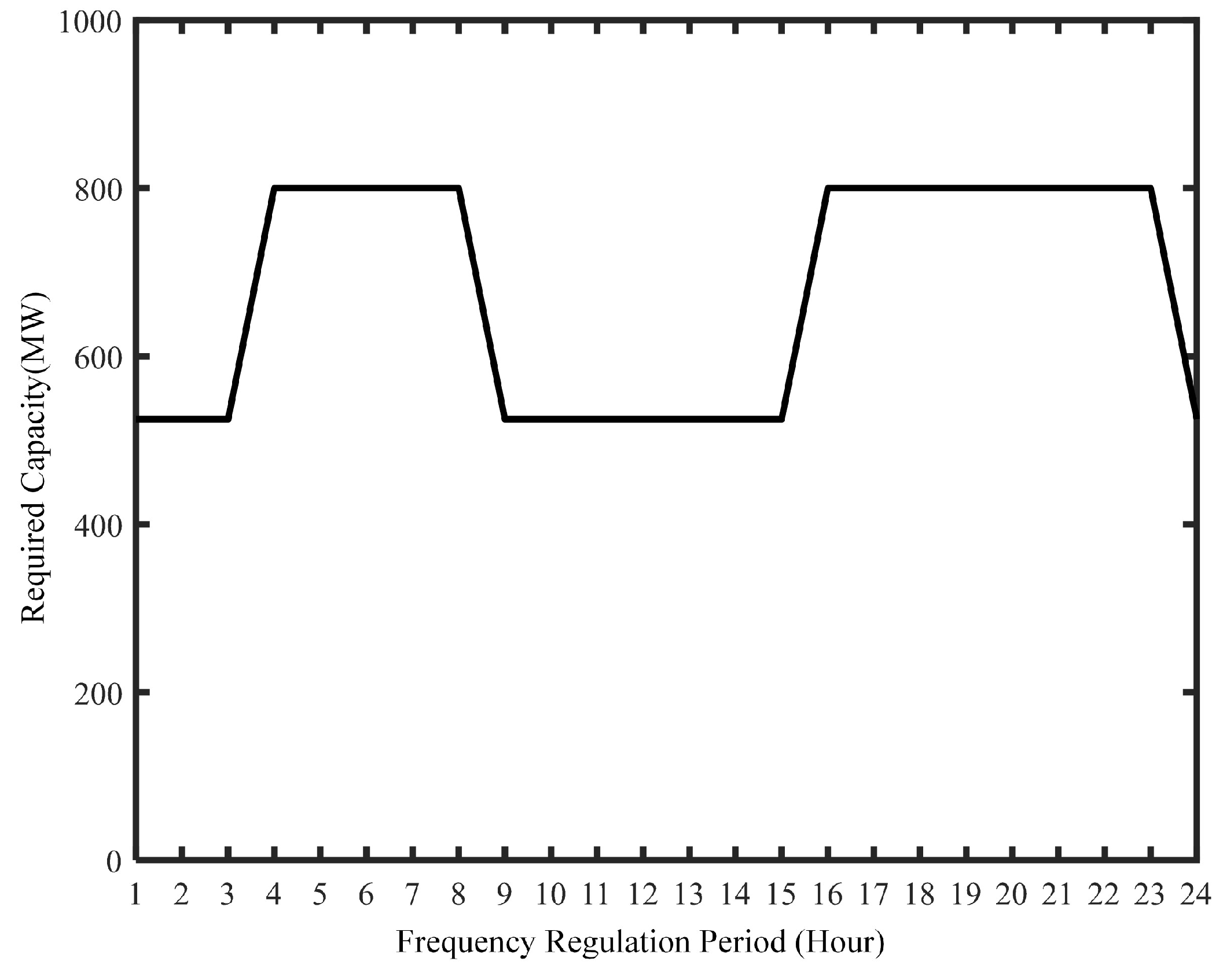
The multifrequency response services provided by the HESS essentially involve charging and discharging processes, which result in electricity losses. Thus, there is a need to pay for the consumed electricity, which can be expressed as
C y EL = E y Loss × π E
E y Loss = E y LBC E y LBD + E y SCC E y SCD
where E y Loss denotes the electricity loss of the HESS in the y-th year. π E denotes the electricity price. E y LBC and E y LBD respectively denote the charging and discharging electricity of the Li-ion battery in the y-th year. E y SCC and E y SCD respectively denote the charging and discharging electricity of the supercapacitor in the y-th year.
The full lifecycle economic assessment process of the HESS for multitype frequency response is illustrated in Figure 5. In this paper, the frequency regulation ancillary service market-clearing model is modeled using the Yalmip optimization solver tool on the MATLAB platform and utilizes the large-scale mathematical programming optimizer Gurobi for solving [32].

5. Case Study

In order to systematically analyze the economics of a HESS providing multitype frequency response services, this section involves conducting case studies from three perspectives: frequency regulation ancillary service market clearing, cost–benefit analysis of the HESS, and sensitivity analysis of key factors. The basic parameters of the HESS are presented in Table 1. For the PFR benefits of the HESS, the Nordic Grid Swedish Power-Grid Frequency Data [33] are utilized, with a dataset consisting of Nordic grid frequency values for the year 2020 and a time resolution of 20 ms. Based on this typical power system frequency variation, the power trajectory of the HESS for PFR is characterized, and subsequently, benefits and lifetime losses are calculated. The deadband frequency for PFR is set at 0.033 Hz.
For the benefits of the HESS participating in SFR, historical data from the PJM market in the United States are employed for validation. The case data include the frequency regulation capacity requirements, clearing prices for frequency regulation resources, and average frequency regulation mileage for each time period. In the PJM market, frequency regulation resources are cleared every hour, and there are two types of capacity requirements in different time periods, namely 525 MW and 800 MW, as detailed in Figure 6. Additionally, λ AA , λ RT , and λ RS are set at 0.4, 0.4, and 0.2, respectively.
Furthermore, in order to simulate the competitive state of the HESS in the frequency regulation ancillary service market, an additional nine frequency regulation resource entities are introduced to participate in the market. Together with the HESS, they undergo simulated clearing for various time periods. The frequency regulation capacities and performance metrics of these frequency regulation resources are presented in Table 2.

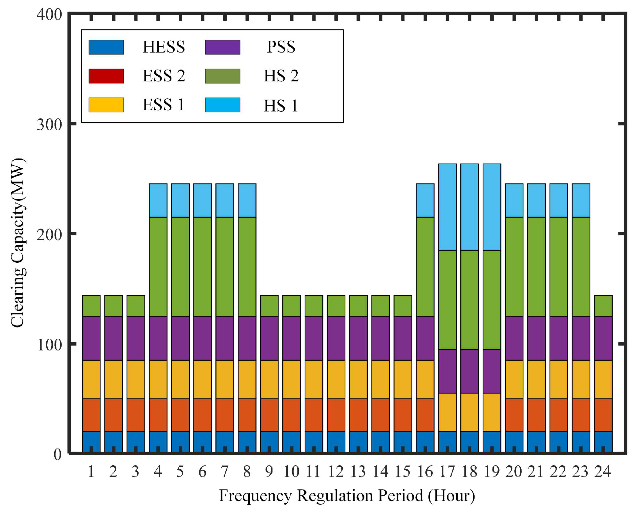
5.1. Frequency Regulation Ancillary Service Market-Clearing Results

To comprehensively reflect the impact of each frequency regulation resource’s physical performance on the clearing results, this study assumes that all resources have the same initial bids. The initial mileage bid is set at 2 CNY/MW, and the initial capacity bid is set at 0.33 CNY/MW. To prevent poor-performing thermal power units from excessively inflating the clearing mileage prices, a cap of 5 CNY/MW is placed on mileage prices. Based on these parameters, the adjusted frequency regulation resource bids after performance metric correction are presented in Table 3. From Table 3, it can be observed that due to the lower performance metrics of thermal power units, the adjusted capacity and mileage prices are the highest among the various types of frequency regulation resources. In particular, the mileage price even exceeds the upper limit and is constrained to 5 CNY/MW. On the other hand, when different types of resources have equal bids and well-matched performance metrics, their comprehensive prices are lower. For example, the HESS has the highest performance metric of 0.994, resulting in the lowest comprehensive price of 2.3441 CNY/MW, making it a priority for clearing (provided SOC constraints are satisfied).
Next, the utility factors for each frequency regulation resource are calculated, converting actual physical capacity into utility capacity, which serves as the basis for capacity clearing. The converted utility capacities are presented in Table 4. As shown in Table 4, high-quality frequency regulation resources, including hydropower units, pumped storage systems, and ESSs, all have utility factors significantly exceeding 1. This indicates that they can provide effects far superior to those of thermal power units during actual frequency regulation processes. The utility factor of the HESS is 4.327, suggesting that the actual 20 MW capacity of the HESS can meet a frequency regulation capacity demand of 86.534 MW.
Finally, based on the frequency regulation ancillary service market-clearing model as shown in Equation (15), combined with the demand and utility capacities for each time period, the clearing results are illustrated in Figure 7. From the figure, it can be observed that the frequency regulation resources in the market are cleared in the order of HESS, ESS 2, ESS 1, PS, HU 2, and HU 1. When the demand capacity is 525 MW, HU 2 is the marginal unit. When the demand capacity is 800 MW, HU 1 becomes the marginal unit. It is worth noting that ESS 2 not only participates in the frequency regulation ancillary service market but also engages in the electricity energy market. During the three time periods from 17:00 to 19:00, the stored energy of ESS 2 fails to satisfy the SOC constraint, resulting in a lower comprehensive price during these periods, but it cannot be cleared.
Importantly, due to the superior frequency regulation performance of the HESS, it can still clear the market even if it offers higher capacity and mileage bids. When the demand capacity is 525 MW and HU 2 is the marginal clearing unit, as long as the HESS’s capacity bid is below 0.52 CNY/MW and its mileage bid is below 3.15 CNY/MW, it will still clear the market. This raises the clearing price in the market, allowing the clearing unit to gain higher revenue (though increasing the overall frequency regulation cost for the market as a whole). In summary, high-quality frequency regulation resources like the HESS have an advantage in market clearing and can further enhance revenue by adjusting bidding strategies. The frequency regulation ancillary service market should also use market parameters such as utility factors more sensibly to obtain better frequency regulation resources while reducing the overall frequency regulation cost.

5.2. Economic Analysis of HESS

Based on statistical data from actual energy storage projects in China [34], the prices of the HESS, maintenance costs, and electricity prices were obtained, as shown in Table 5. Based on Equations (29)–(32), the cost of the HESS can be determined.
In terms of benefits, firstly, the compensation price for inertia response services is set at 5 CNY/MWh. Assuming the HESS operates throughout the year and supercapacitors consistently provide inertia response services, the inertia response benefits are calculated for a year of service. Then, using the Nordic Grid Swedish Power-Grid Frequency Data, K PFR is set at 500 MW/Hz. Typical grid frequency curves and the HESS’s PFR power curves are shown in Figure 8. From the figure, it is evident that the HESS outputs the corresponding power when grid frequency regulation extends beyond the deadband. With the compensation price for PFR services set at 75,000 CNY/MWh, the PFR benefits of the HESS are calculated.
Finally, as mentioned in Section 5.2, the capacity bid and mileage bid for the HESS are set at 0.33 CNY/MW and 2 CNY/MW, respectively. Based on the clearing results, the awarded capacity for the HESS can be determined. Based on the empirical data from the PJM market, the frequency regulation mileage for three typical days is shown in Figure 9. The figure illustrates that in most time periods, the frequency regulation mileage exceeds 20, with an average of 32, implying that each MW of the frequency regulation resources can provide 32 MW of frequency regulation mileage in each time period. By utilizing the 2022 full-year frequency regulation mileage data from the PJM market, the SFR benefits of the HESS are calculated.
Based on the power trajectory of the Li-ion battery providing PFR and SFR services, the HESS’s lifetime is determined. As the PFR service involves fewer cycles with shorter durations, and is subjected to rain-flow counting, only 3 charge–discharge cycles are conducted per year. Consequently, SFR predominantly contributes to lifetime losses. A typical SFR power trajectory is shown in Figure 10. During SFR, supercapacitors initially output power during the HESS’s positive–negative transition, thereby reducing the wear on Li-ion batteries. Finally, by combining the PJM market frequency regulation mileage data with the power trajectory of SFR service, the lifetime of the HESS is calculated to be 8.4 years.
In conclusion, the full lifecycle economic benefit of the HESS amounts to CNY 36.55 million.

5.3. Analysis of Key Factors Affecting the Economic Viability of the HESS

Assuming the absence of supercapacitors, certain effects would be observed. On one hand, the ESS would no longer provide inertia response services, and on the other hand, the PFR power would decrease. Furthermore, in the absence of supercapacitors, the Li-ion battery would bear the entire burden of SFR, thus exacerbating the level of lifetime degradation. According to calculations, under the same SFR service provision, the lifetime of a standalone Li-ion battery energy storage system would be 7.5 years. Ultimately, the full lifecycle economic benefit under the condition of no supercapacitors amounts to CNY 34.07 million.
As observed in Section 5.2, due to its superior physical characteristics, the HESS can still clear the market even with higher bids. Assuming a capacity bid of 0.52 CNY/MW and a mileage bid of 3.15 CNY/MW, the full lifecycle economic benefit of the HESS would be CNY 82.06 million.

6. Conclusions

This paper proposes an economic analysis method considering the benefits of multitype frequency response for a Li-ion battery–supercapacitor HESS. Subsequently, the effectiveness of the proposed method is validated using actual power system frequency data and PJM market data, leading to the following conclusions:
(1)
Due to the HESS’s strong performance in terms of regulation accuracy, response time, and regulation speed, it exhibits robust competitiveness in the frequency regulation ancillary service market when priced competitively with other frequency regulation resources. This positions the HESS to actively participate in frequency response services.
(2)
By providing multitype frequency response services including inertia response, PFR, and SFR, the HESS can diversify its revenue streams and achieve higher returns. The inclusion of supercapacitors not only enhances the HESS’s performance but also effectively mitigates the lifetime degradation of Li-ion batteries, thereby improving overall economic viability.
In future research, the proposed economic analysis method can be extended to explore capacity configuration strategies for HESSs.

Author Contributions

Conceptualization, C.X., W.Q. and Z.L.; methodology, C.X., W.Q. and L.S.; software, C.X., T.Z., J.L. (Jun Li) and Z.L.; validation, L.S., G.C. and H.Y.; formal analysis, C.X., J.L. (Jiaqi Lu) and H.Y.; investigation, W.Q., T.Z. and G.C.; resources, L.S. and Z.L.; data curation, W.Q., J.L. (Jiaqi Lu) and H.Y.; writing—original draft preparation, C.X.; writing—review and editing, T.Z., G.C. and Z.L.; visualization, C.X., J.L. (Jun Li) and H.Y; supervision, G.C. and Z.L.; project administration, G.C., T.Z. and Z.L; funding acquisition, L.S., G.C. and H.Y. All authors have read and agreed to the published version of the manuscript.

Funding

This research was funded by Power China Huadong Engineering Corporation Limited.

Data Availability Statement

Not applicable.

Acknowledgments

We appreciate the support from Power China Huadong Engineering Corporation Limited for this work.

Conflicts of Interest

The authors declare no conflict of interest.

References

  1. Liu, S.; Lin, Z.; Jiang, Y.; Zhang, T. Market, Policy, and Technology Requirements for Power Systems Under ‘30–60′ Decarbonization Goal of China. Energy Sustain. Dev. 2022, 70, 339–341. [Google Scholar] [CrossRef]
  2. Liu, B.; Zhu, B.; Guan, Z.; Mao, C.; Wang, D. Energy Router Interconnection System: A solution for New Distribution Network Architecture Toward Future Carbon Neutrality. Energy Convers. Econ. 2022, 3, 181–200. [Google Scholar] [CrossRef]
  3. Kouveliotis-Lysikatos, I.; Hatziargyriou, N.; Liu, Y.; Wu, F. Towards an Internet-like Power Grid. J. Mod. Power Syst. Clean Energy 2022, 10, 1–11. [Google Scholar] [CrossRef]
  4. Liu, S.; Lin, Z.; Zhao, Y.; Liu, Y.; Ding, Y.; Zhang, B.; Yang, L.; Wang, Q.; White, S.E. Robust System Separation Strategy Considering Online Wide-Area Coherency Identification and Uncertainties of Renewable Energy Sources. IEEE Trans. Power Syst. 2020, 35, 3574–3587. [Google Scholar] [CrossRef]
  5. Chen, Y.; Lao, K.W.; Qi, D.; Hui, H.; Yang, S.; Yan, Y.; Zheng, Y. Distributed Self-triggered Control for Frequency Restoration and Active Power Sharing in Islanded Microgrids. IEEE Trans. Ind. Electron. 2023, 19, 10635–10646. [Google Scholar] [CrossRef]
  6. Peña, A.A.; Romero-Quete, D.; Cortes, C.A. Sizing and Siting of Battery Energy Storage Systems: A Colombian Case. J. Mod. Power Syst. Clean Energy 2022, 10, 700–709. [Google Scholar] [CrossRef]
  7. Hossain, E.; Faruque, H.M.R.; Sunny, M.S.H.; Mohammad, N.; Nawar, N. A Comprehensive Review on Energy Storage Systems: Types, Comparison, Current Scenario, Applications, Barriers, and Potential Solutions, Policies, and Future Prospects. Energies 2020, 13, 3651. [Google Scholar] [CrossRef]
  8. Chen, C.; Li, Y.; Qiu, W.; Liu, C.; Zhang, Q.; Li, Z.; Lin, Z.; Yang, L. Cooperative-game-based Day-Ahead Scheduling of Local Integrated Energy Systems with Shared Energy Storage. IEEE Trans. Sustain. Energy 2022, 13, 1994–2011. [Google Scholar] [CrossRef]
  9. Qiu, W.; Zhou, S.; Yang, Y.; Lv, X.; Lv, T.; Chen, Y.; Huang, Y.; Zhang, K.; Yu, H.; Wang, Y.; et al. Application Prospect, Development Status and Key Technologies of Shared Energy Storage Toward Renewable Energy Accommodation Scenario in The Context of China. Energies 2023, 16, 731. [Google Scholar] [CrossRef]
  10. Akram, U.; Nadarajah, M.; Shah, R.; Milano, F. A Review on Rapid Responsive Energy Storage Technologies for Frequency Regulation in Modern Power Systems. Renew. Sust. Energ. Rev. 2020, 120, 109626. [Google Scholar] [CrossRef]
  11. Cavallo, A.; Canciello, G.; Russo, A. Supervised Energy Management in Advanced Aircraft Applications. In Proceedings of the 2018 European Control Conference (ECC), Limassol, Cyprus, 12–15 June 2018; Volume 1, pp. 2769–2774. [Google Scholar]
  12. Zhang, J.; Chen, Z.; Zhang, N.; Zhang, X. Frequency-Constrained Unit Commitments with Linear Rules Extracted from Simulation Results Considering Regulations from Battery Storage. J. Mod. Power Syst. Clean Energy 2023, 11, 1041–1052. [Google Scholar] [CrossRef]
  13. Kottick, D.; Blau, M.; Edelstein, D. Battery Energy Storage for Frequency Regulation in An Island Power System. IEEE Trans. Energy Convers. 1993, 8, 455–459. [Google Scholar] [CrossRef]
  14. Ma, Y.; Hu, Z.; Song, Y. Hour-ahead Optimization Strategy for Shared Energy Storage of Renewable Energy Power Stations to Provide Frequency Regulation Service. IEEE Trans. Sustain. Energy 2022, 13, 2331–2342. [Google Scholar] [CrossRef]
  15. Stroe, D.I.; Knap, V.; Swierczynski, M.; Stroe, A.I.; Teodorescu, R. Operation of A Grid-Connected Lithium-Ion Battery Energy Storage System for Primary Frequency Regulation: A Battery Lifetime Perspective. IEEE Trans. Ind. Appl. 2016, 53, 430–438. [Google Scholar] [CrossRef]
  16. Russo, A.; Cavallo, A. Supercapacitor Stability and Control for More Electric Aircraft Application. In Proceedings of the 2020 European Control Conference (ECC), Saint Petersburg, Russia, 12–15 May 2020; Volume 1, pp. 1909–1914. [Google Scholar]
  17. Yang, L.; Hu, Z.; Xie, S.; Kong, S.; Lin, W. Adjustable Virtual Inertia Control of Supercapacitors in PV-based AC Microgrid Cluster. Electr. Power Syst. Res. 2019, 173, 71–85. [Google Scholar] [CrossRef]
  18. Sarojini, R.K.; Palanisamy, K.; De Tuglie, E. A Fuzzy Logic-Based Emulated Inertia Control to A Supercapacitor System to Improve Inertia in a Low Inertia Grid with Renewables. Energies 2022, 15, 1333. [Google Scholar] [CrossRef]
  19. Iqbal, M.Z.; Aziz, U. Supercapattery: Merging of Battery-Supercapacitor Electrodes for Hybrid Energy Storage Devices. J. Energy Storage 2022, 46, 103823. [Google Scholar] [CrossRef]
  20. Hajiaghasi, S.; Salemnia, A.; Hamzeh, M. Hybrid Energy Storage System for Microgrids Applications: A Review. J. Energy Storage 2019, 21, 543–570. [Google Scholar] [CrossRef]
  21. Bharatee, A.; Ray, P.K.; Ghosh, A. A Power Management Scheme for Grid-connected PV Integrated with Hybrid Energy Storage System. J. Mod. Power Syst. Clean Energy 2022, 10, 954–963. [Google Scholar] [CrossRef]
  22. Fang, J.; Tang, Y.; Li, H.; Li, X. A Battery/ultracapacitor Hybrid Energy Storage System for Implementing the Power Management of Virtual Synchronous Generators. IEEE Trans. Power Electron. 2017, 33, 2820–2824. [Google Scholar] [CrossRef]
  23. Zhou, X.; Dong, C.; Fang, J.; Tang, Y. Enhancement of load Frequency Control by Using a Hybrid Energy Storage System. In Proceedings of the 2017 Asian Conference on Energy, Power and Transportation Electrification (ACEPT), Singapore, 24–26 October 2017; Volume 1, pp. 1–6. [Google Scholar]
  24. Gu, Y.; Li, W.; He, X. Frequency-coordinating Virtual Impedance for Autonomous Power Management of DC Microgrid. IEEE Trans. Power Electron. 2014, 30, 2328–2337. [Google Scholar] [CrossRef]
  25. Chirkin, V.G.; Lezhnev, L.Y.; Petrichenko, D.A.; Papkin, I.A. A Battery-supercapacitor Hybrid Energy Storage System Design and Power Management. Int. J. Pure Appl. Math. 2018, 119, 2621–2625. [Google Scholar]
  26. Yang, J.; Dong, Z.Y.; Wen, F.; Chen, Q.; Liang, B. Spot Electricity Market Design for a Power System Characterized by High Penetration of Renewable Energy Generation. Energy Convers. Econ. 2021, 2, 67–78. [Google Scholar] [CrossRef]
  27. Liu, S.; You, S.; Lin, Z.; Zeng, C.; Li, H.; Wang, W.; Hu, X.; Liu, Y. Data-Driven Event Identification in The US Power Systems Based on 2D-OLPP And Rusboosted Trees. IEEE Trans. Power Syst. 2021, 37, 94–105. [Google Scholar] [CrossRef]
  28. Tarimo, D.J.; Mirghni, A.A.; Oyedotun, K.O.; Rutavi, G.; Kitenge, V.N.; Manyala, N. Recycling of Biomass Wastes from Amarula Husk by A Modified Facile Economical Water Salt Method for High Energy Density Ultracapacitor Application. J. Energy Storage 2022, 53, 105166. [Google Scholar] [CrossRef]
  29. Babu, T.S.; Vasudevan, K.R.; Ramachandaramurthy, V.K.; Sani, S.B.; Chemud, S.; Lajim, R.M. A Comprehensive Review of Hybrid Energy Storage Systems: Converter Topologies, Control Strategies and Future Prospects. IEEE Access 2020, 8, 148702–148721. [Google Scholar] [CrossRef]
  30. Cheng, T.; Lu, D.D.C.; Siwakoti, Y.P. Circuit-Based Rainflow Counting Algorithm in Application of Power Device Lifetime Estimation. Energies 2022, 15, 5159. [Google Scholar] [CrossRef]
  31. Zhang, C.; Liu, L.; Cheng, H.; Liu, D.; Zhang, J.; Li, G. Frequency-constrained Co-planning of Generation and Energy Storage with High-penetration Renewable Energy. J. Mod. Power Syst. Clean Energy 2021, 9, 760–775. [Google Scholar] [CrossRef]
  32. Vardhan, B.S.; Khedkar, M.; Srivastava, I. Effective Energy Management and Cost Effective Day Ahead Scheduling for Distribution System with Dynamic Market Participants. Sustain. Energy Grids Netw. 2022, 31, 100706. [Google Scholar] [CrossRef]
  33. Gorjão, L.R.; Schäfer, B.; Witthaut, D.; Beck, C. Spatio-temporal Complexity of Power-Grid Frequency Fluctuations. N. J. Phys. 2021, 23, 073016. [Google Scholar] [CrossRef]
  34. Liu, Y.; Zheng, R.; Chen, S.; Yuan, J. The Economy of Wind-integrated-energy-storage Projects in China’s Upcoming Power Market: A Real Options Approach. Resour. Policy 2019, 63, 101434. [Google Scholar] [CrossRef]
Figure 1. Typical timing diagram of frequency response in power systems.
Energies 16 06621 g001
Figure 2. The diagram of SFR in the frequency regulation ancillary service market.
Energies 16 06621 g002
Figure 3. Collaborative control strategy for Li-ion battery and supercapacitor in SFR.
Energies 16 06621 g003
Figure 4. The diagram of rain-flow counting method.
Energies 16 06621 g004
Figure 5. The flowchart of the full lifecycle economic assessment process of the HESS.
Energies 16 06621 g005
Figure 6. The demand for SFR capacity in the PJM market.
Energies 16 06621 g006
Figure 8. Typical grid frequency curves and the HESS’s PFR power curve.
Energies 16 06621 g008
Figure 9. The frequency regulation mileage of the PJM market for three typical days.
Energies 16 06621 g009
Figure 10. A typical SFR power trajectory.
Energies 16 06621 g010
Figure 7. The results of frequency regulation ancillary service market-clearing model.
Energies 16 06621 g007
Table 1. The basic parameters of the HESS.
ComponentAttributeValue
Li-ion batteryInstalled capacity20 MW/20 MWh
Cycle efficiency85%
Lifecycles 6000
SupercapacitorInstalled capacity5 MW/0.0834 MWh
Cycle efficiency90%
Lifecycles1,000,000
Table 2. Basic parameters of the frequency regulation resources in the frequency regulation ancillary service market.
Resource TypeTagSFR Capacity (MW)Regulation Accuracy ScoreResponse Time ScoreAdjustment Speed ScorePerformance Metrics
Thermal power unitTU 11200.250.290.100.236
TU 21500.210.390.100.260
TU 31000.190.360.150.250
TU 41600.150.260.100.184
Hydropower unitHU 11000.610.820.180.608
HU 2900.670.790.230.630
Pumped storagePS400.780.550.550.642
Energy storage systemESS 1351.001.000.840.968
ESS 2301.001.000.880.976
HESSHESS201.001.000.970.994
Table 3. The adjusted frequency regulation resource bids after performance metric correction.
ResourceAdjusted Capacity Price (CNY/MW)Adjusted Mileage Price (CNY/MW)Comprehensive Price (CNY/MW)
TU 11.39856.398
TU 21.26956.269
TU 31.32056.320
TU 41.79356.793
HU 10.5433.28953.8325
HU 20.5243.17463.6986
PS0.5143.11533.6293
ESS 10.3412.06612.4071
ESS 20.3382.04922.3872
HESS0.3322.01212.3441
Table 4. Converted utility capacities of the regulation resources.
ResourceUtility FactorsSFR Capacity (MW)Utility Capacity (MW)
TU 11.027120123.272
TU 21.132150169.760
TU 31.088100108.821
TU 40.801160128.147
HU 12.647100264.652
HU 22.74290246.805
PS2.79540111.781
ESS 14.21435147.474
ESS 24.24830127.451
HESS4.3272086.534
Table 5. Cost parameters of the HESS.
AttributeValue
Li-ion battery price1.1 million CNY/MWh
Supercapacitor price70 million CNY/MWh
Converter price0.75 million CNY/MW
Discount rate5%
Electricity price400 CNY/MWh
Maintenance costs0.5 million CNY/a
Disclaimer/Publisher’s Note: The statements, opinions and data contained in all publications are solely those of the individual author(s) and contributor(s) and not of MDPI and/or the editor(s). MDPI and/or the editor(s) disclaim responsibility for any injury to people or property resulting from any ideas, methods, instructions or products referred to in the content.

