
Multifunctional Control Technique for Grid-Tied Hybrid Distributed Generation System Taking into Account Power Quality Issues


 ,
,  ,
, 

Abstract
:1. Introduction
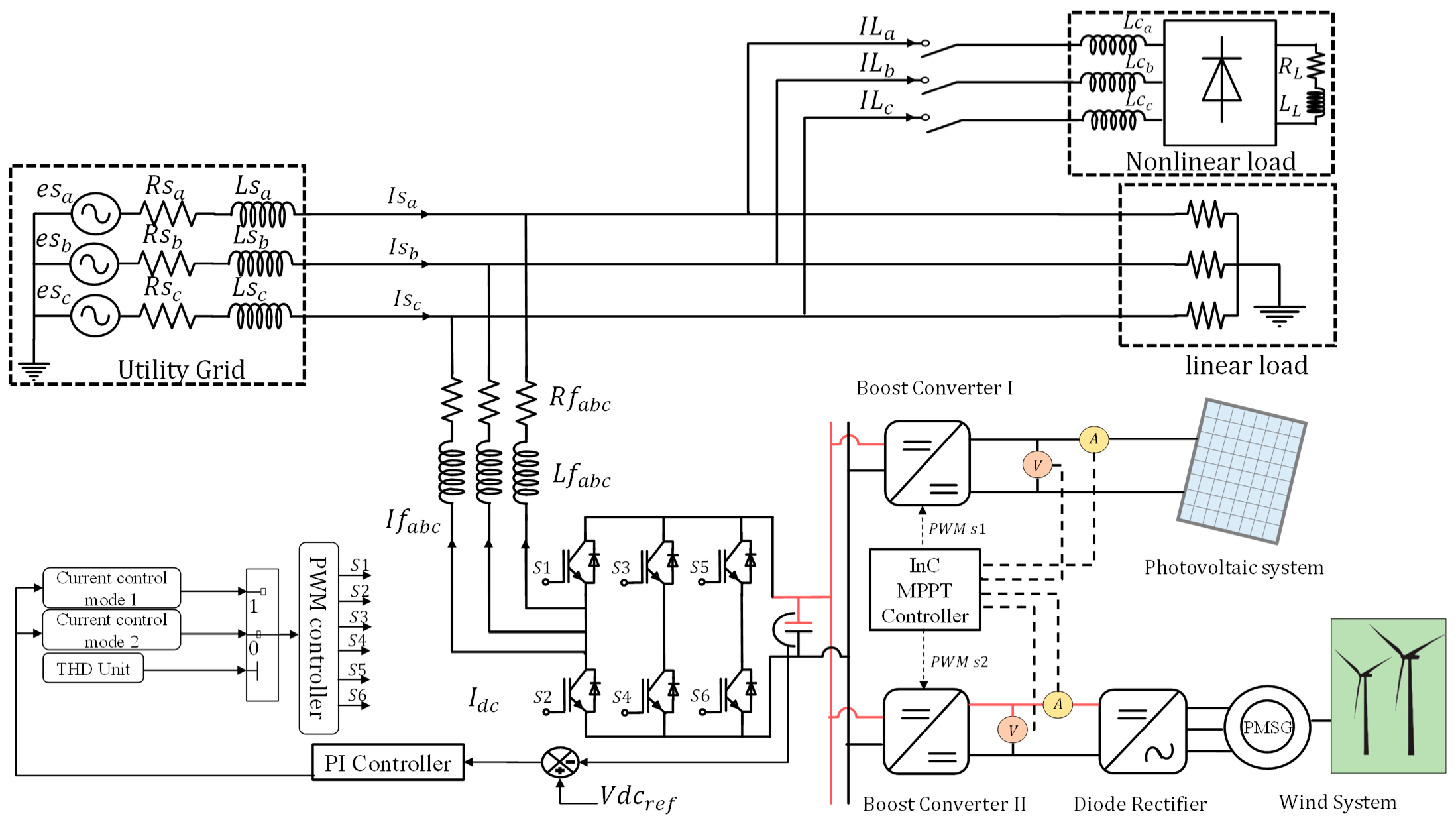
2. System Description
2.1. The Stand-Alone System Modeling
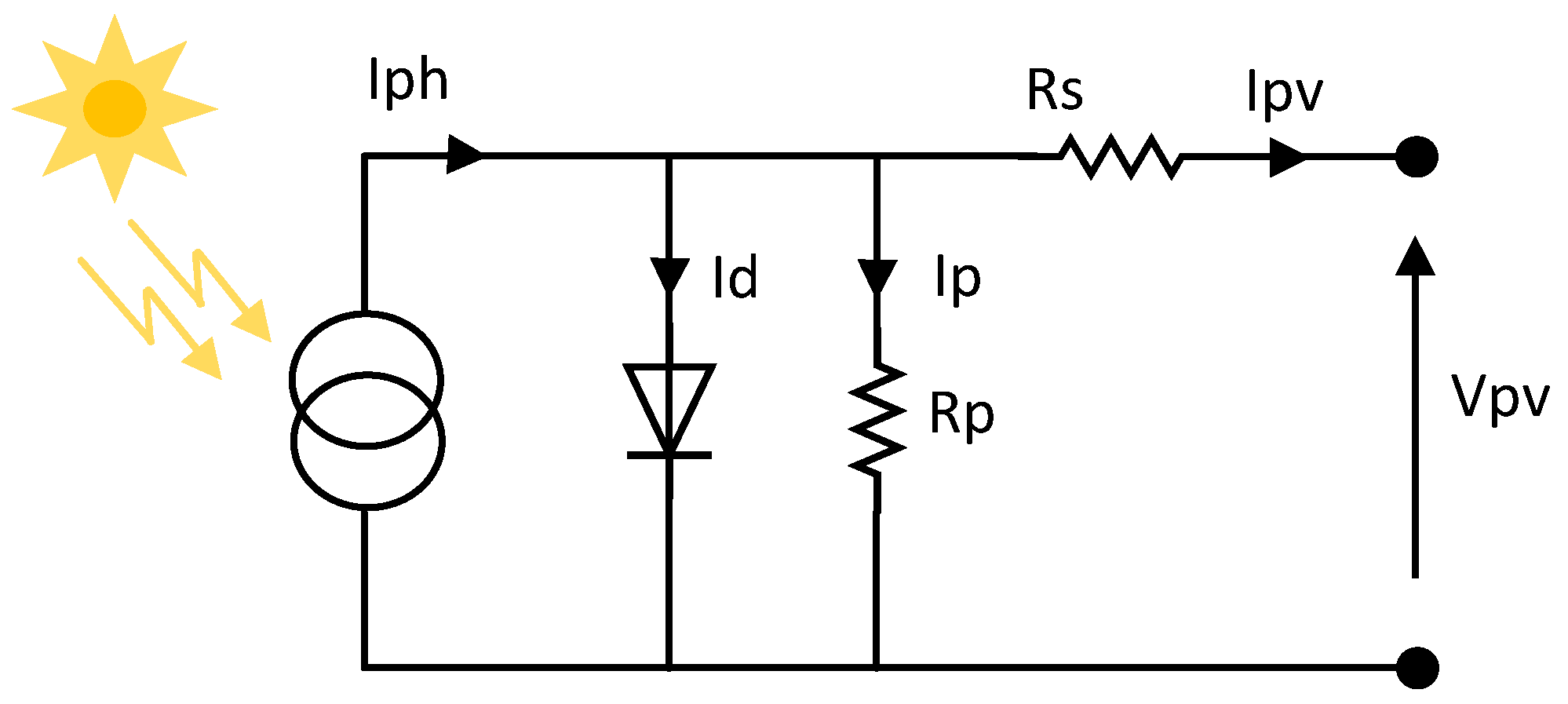
2.1.1. PV System Modeling
2.1.2. Wind Energy Conversion System Modeling
- -
- The self-excitation of the PMSG;
- -
- The output voltage of the boost converter can be adjusted to fit the requirements of the inverter;
- -
- The control simplicity;
- -
- The reduced cost.
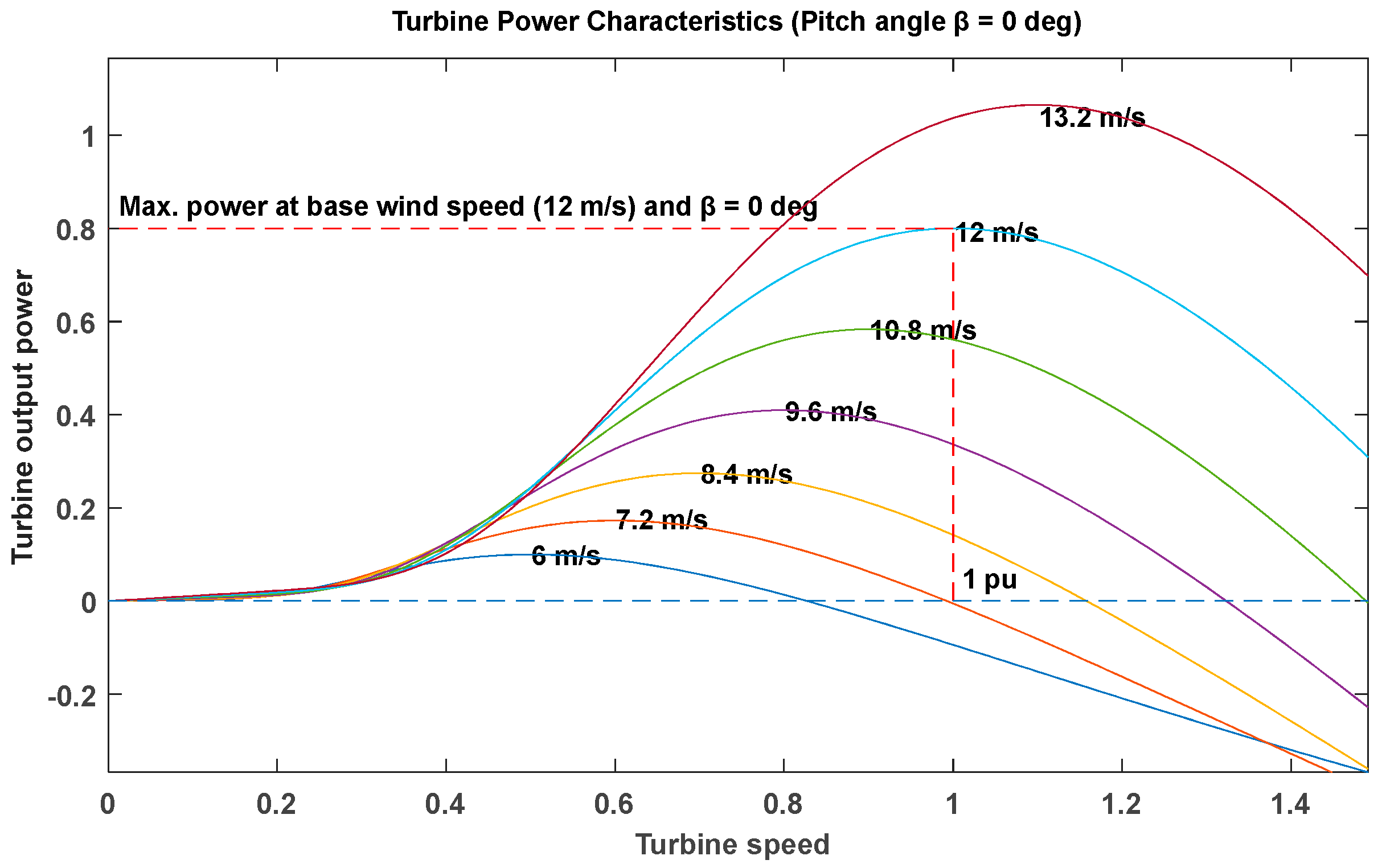
Wind Turbine Modeling
PMSG Modeling
3. The Proposed Control Scheme
3.1. Operatinh Mode 1: Power Injection Operating Mode
3.1.1. The d-q Reference Current Identification
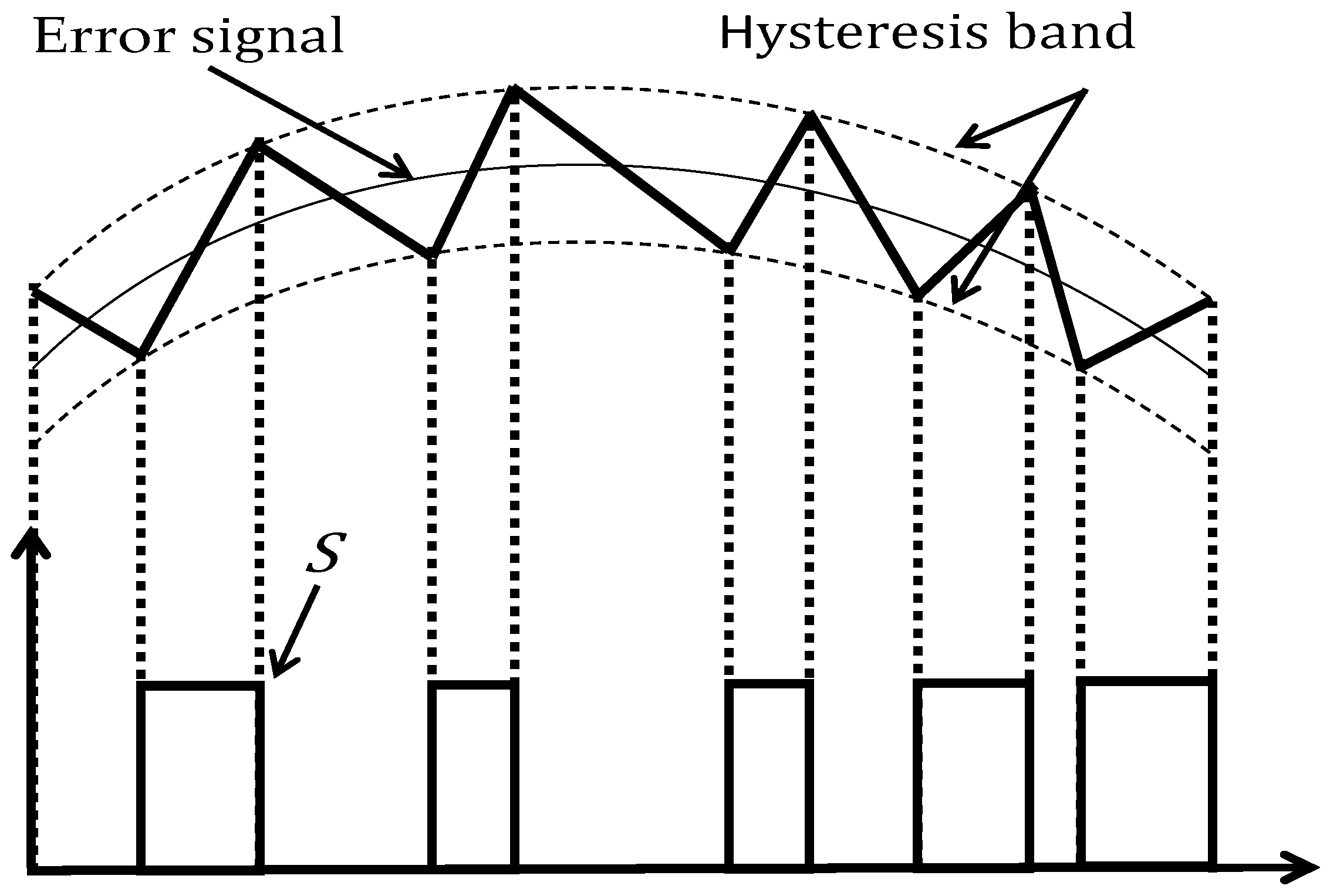
3.1.2. Hysteresis Current Control
3.1.3. Backstepping Current Control
3.2. Operating Mode 2: Power Quality Improvement Operating Mode
3.2.1. Reference Current Identification
3.2.2. Hysteresis Current Control
3.2.3. Backstepping Controller
4. Simulation Results
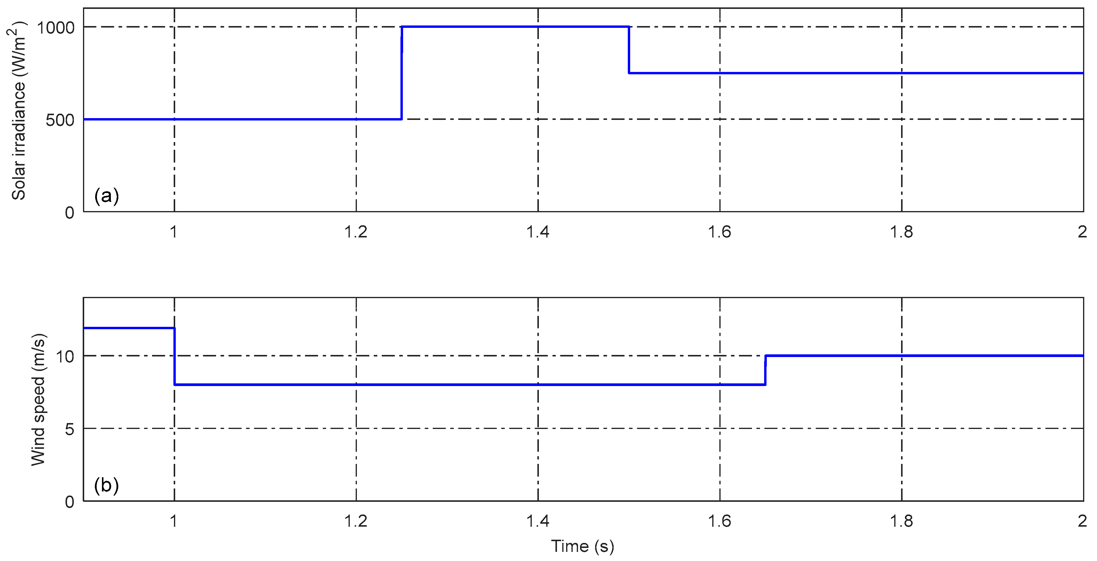
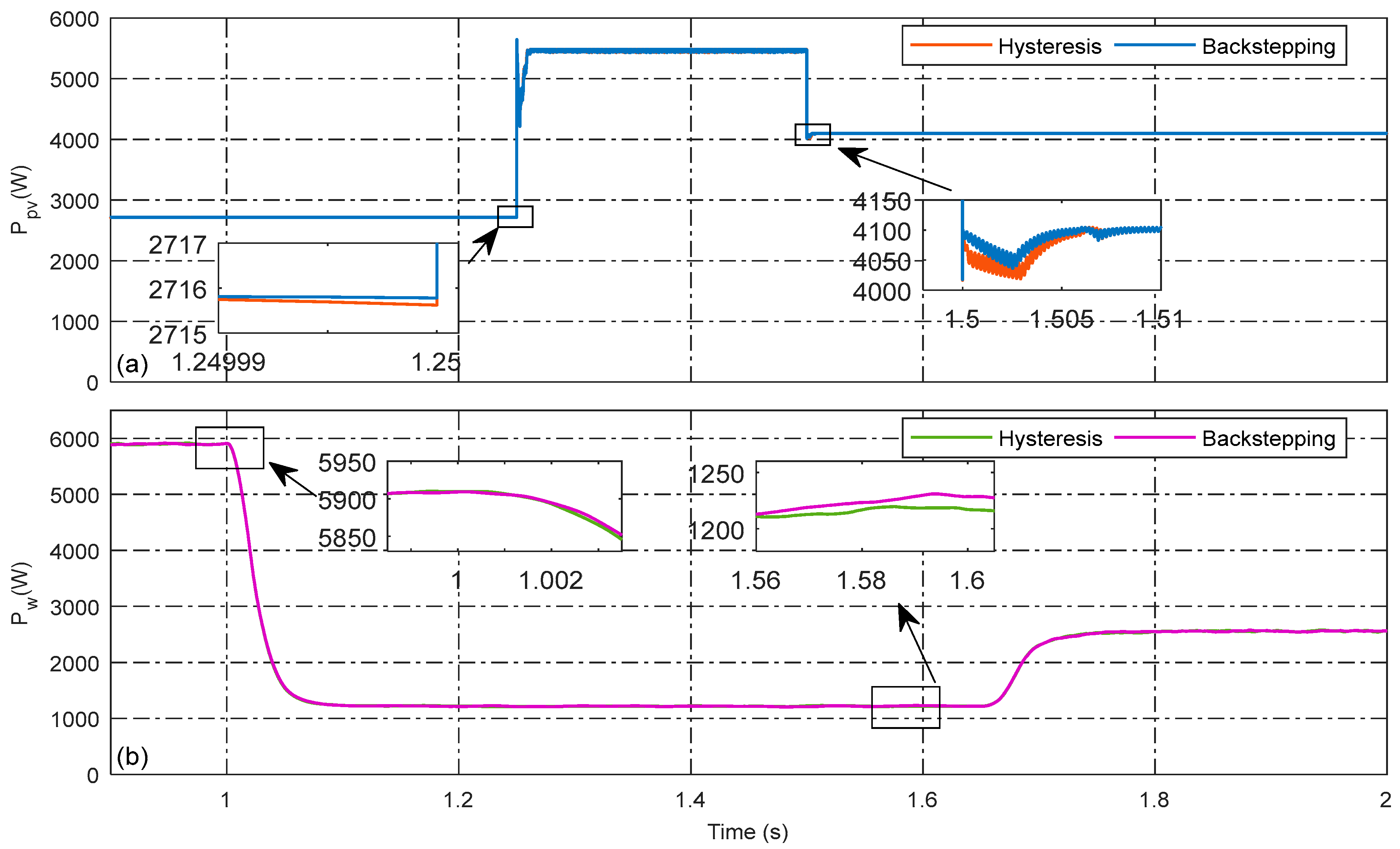
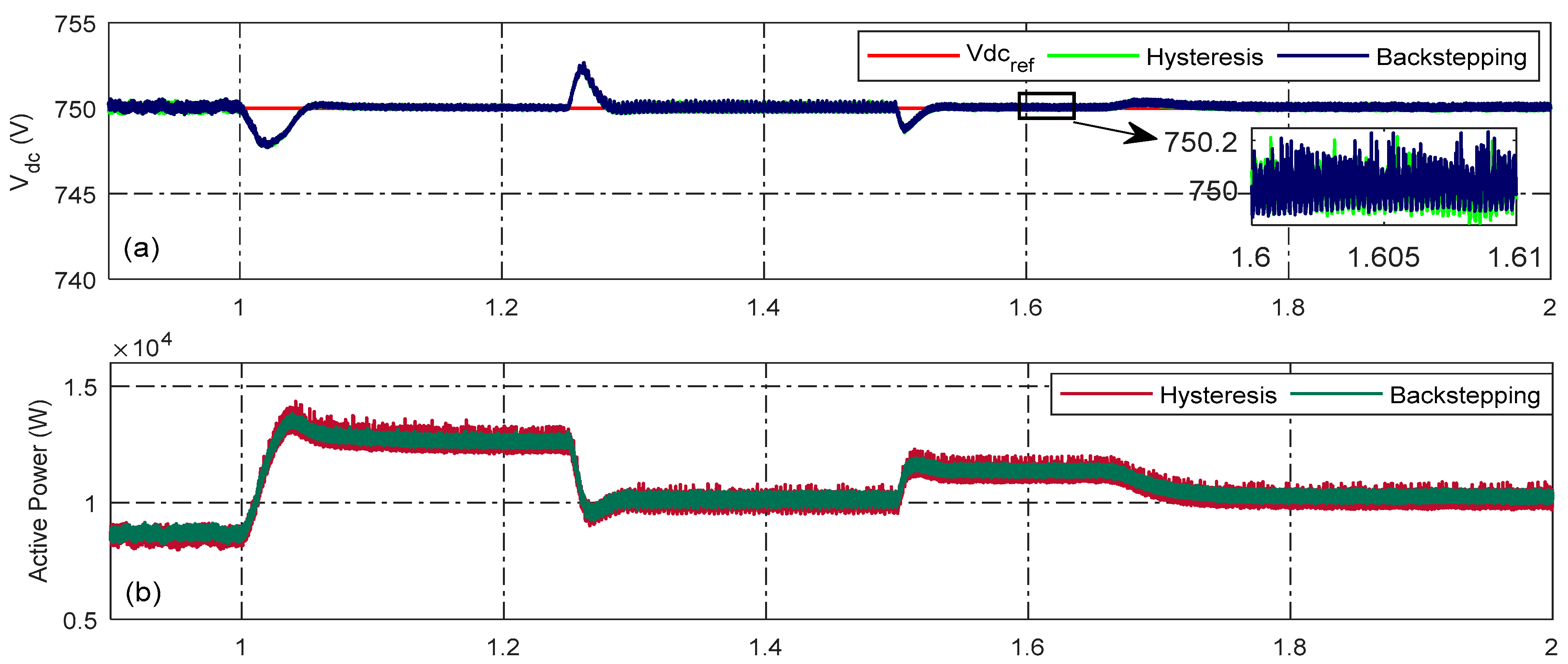
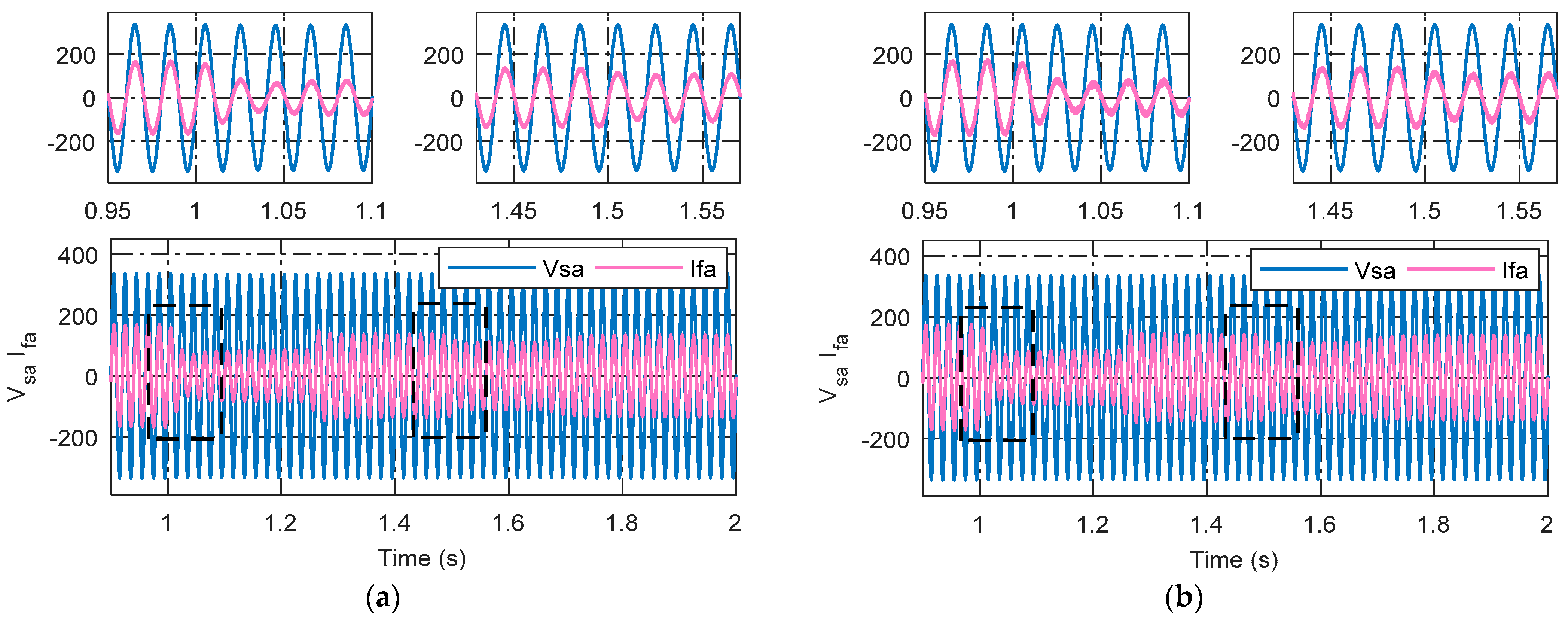
4.1. Operating Mode 1: Power Injection Mode
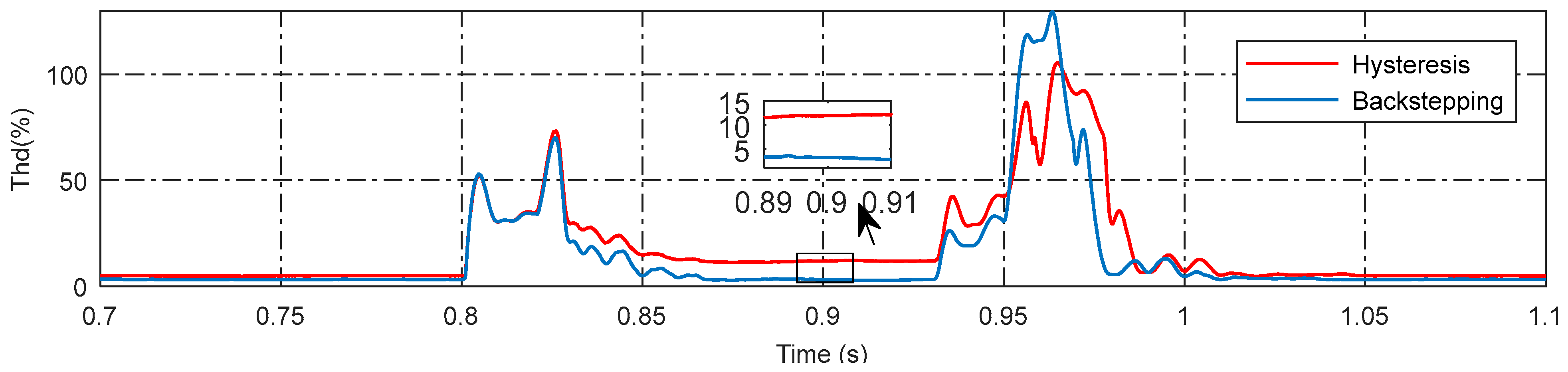
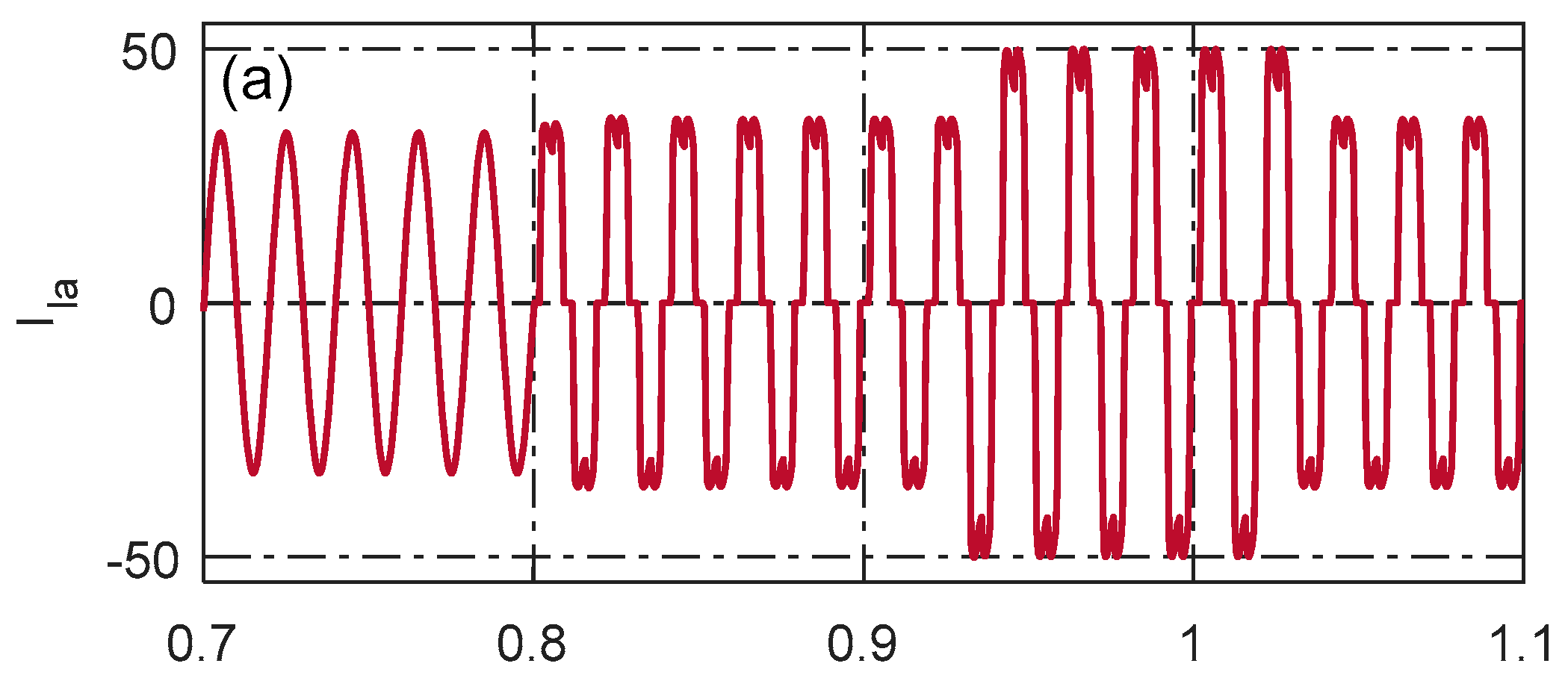
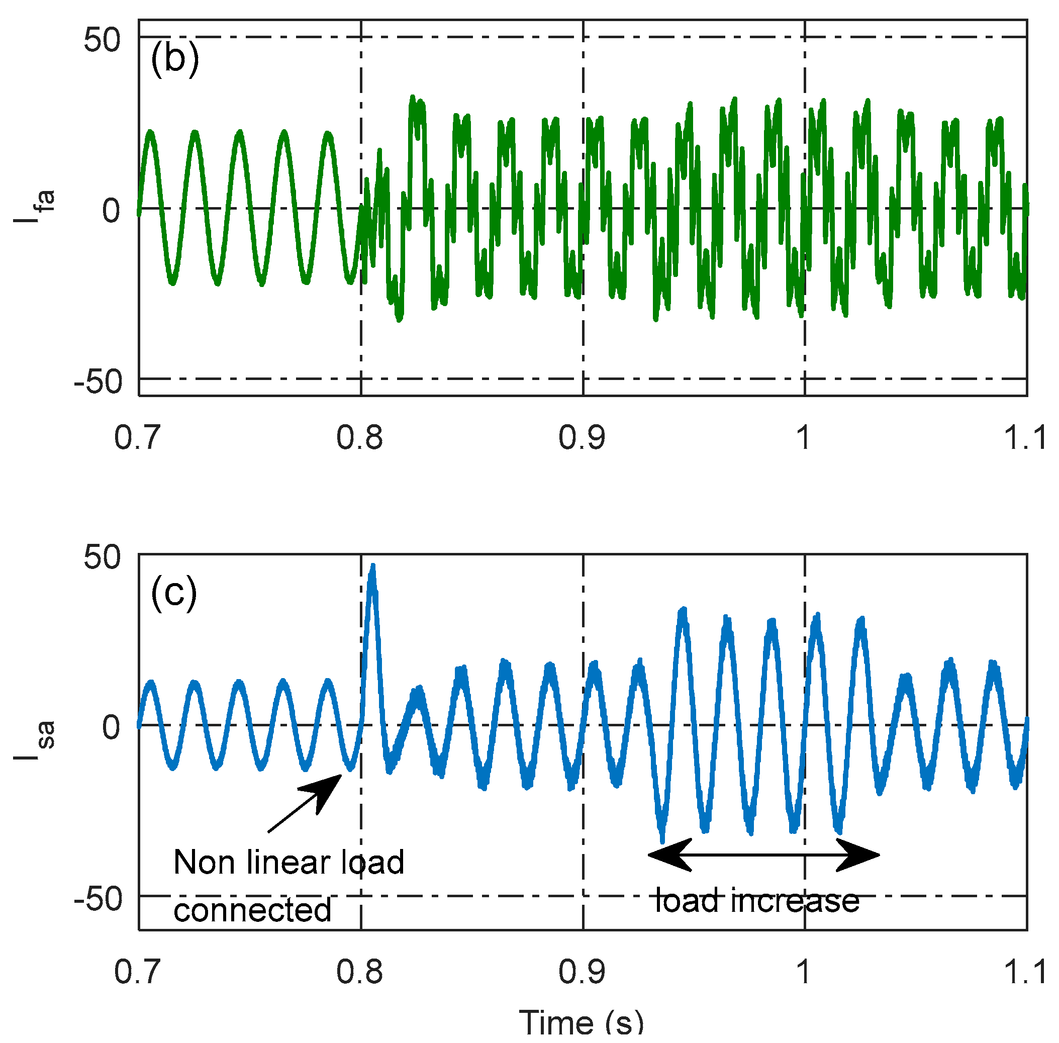
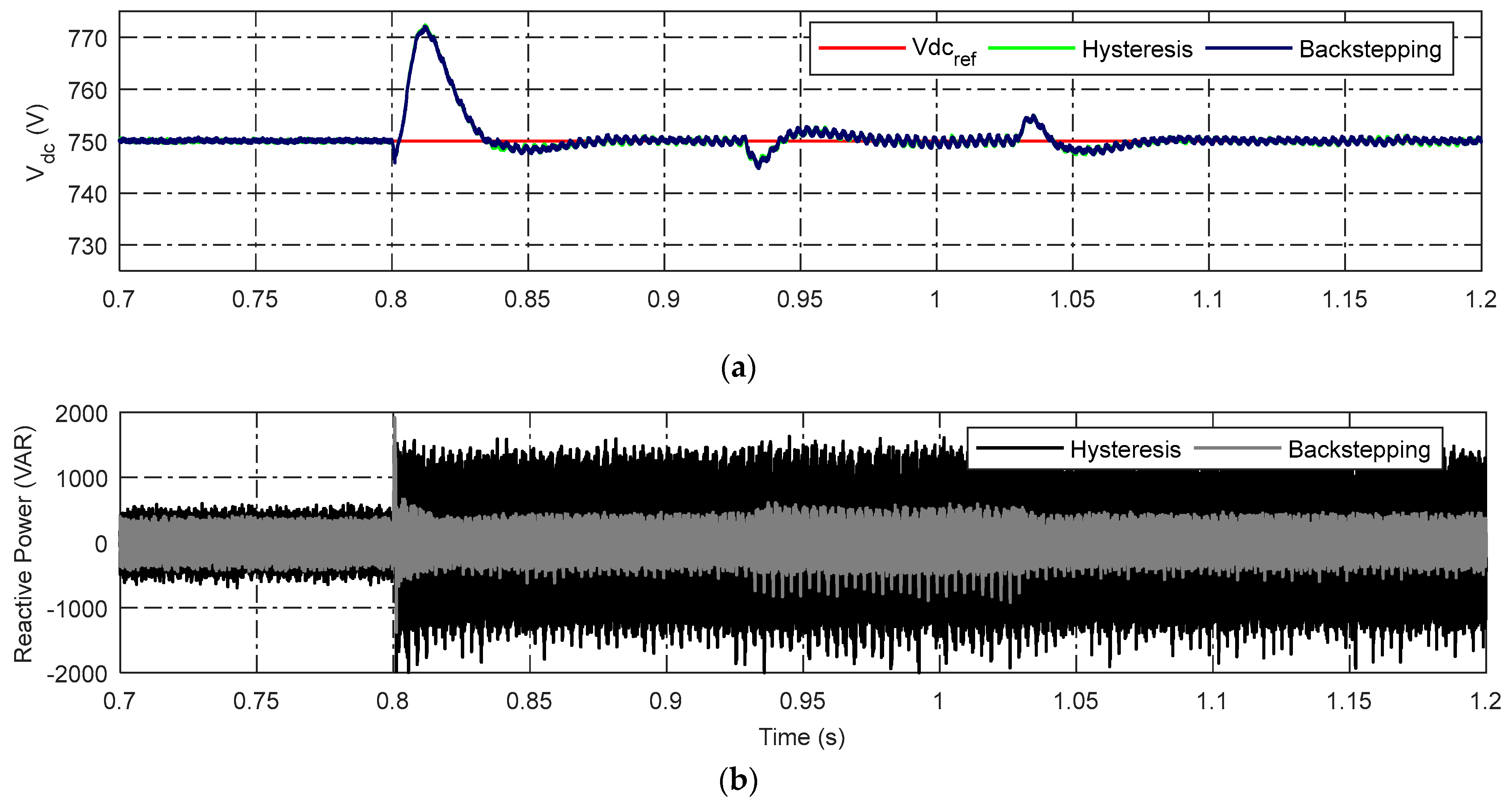
4.2. Operating Mode 2: Power Quality Improvement Mode
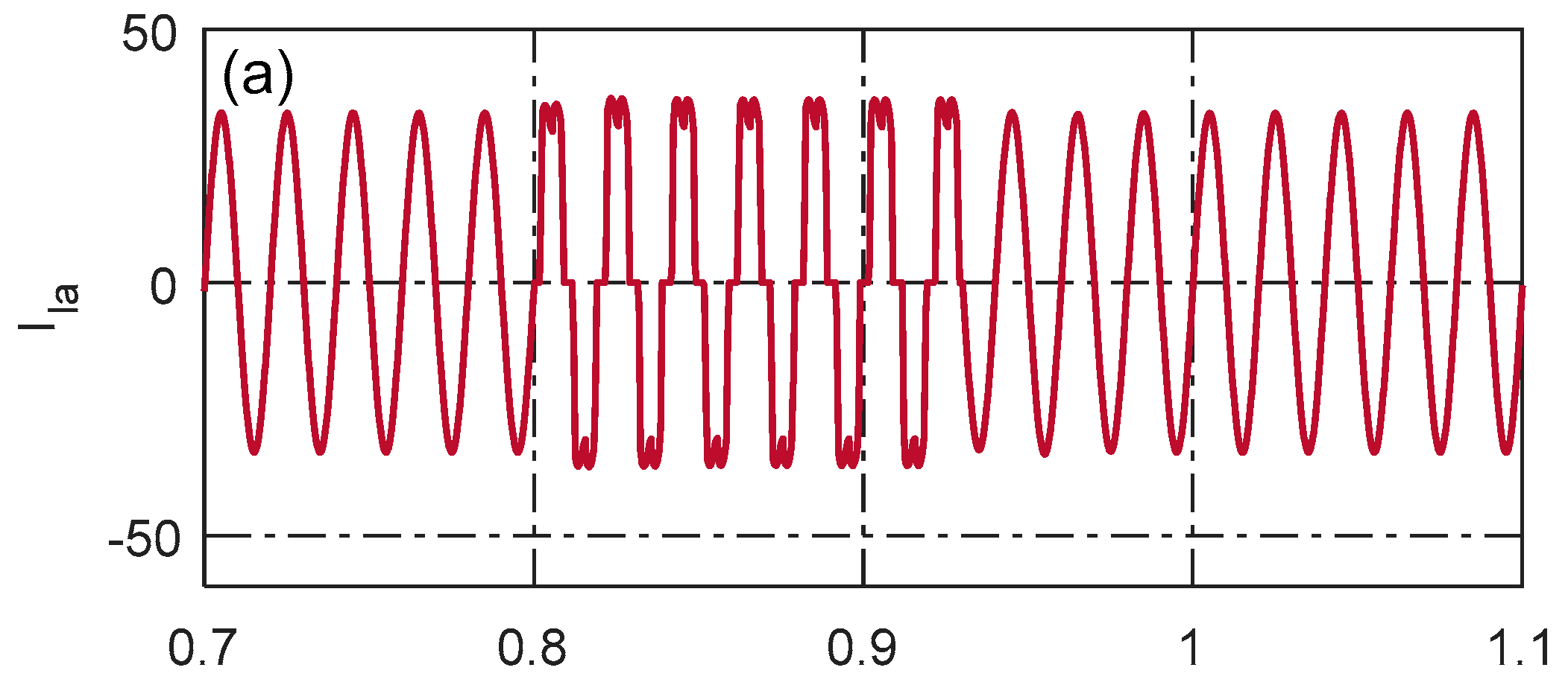
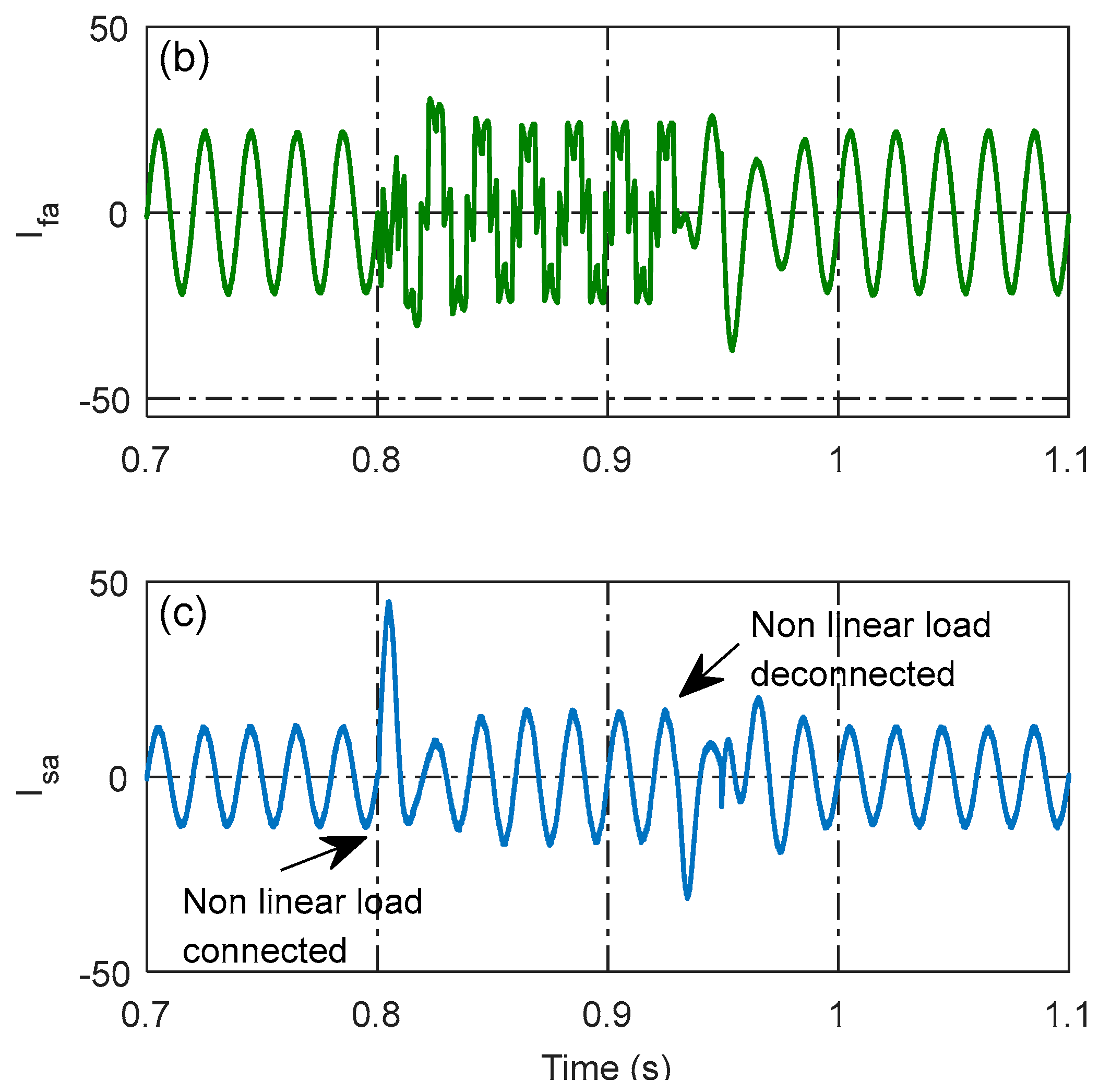
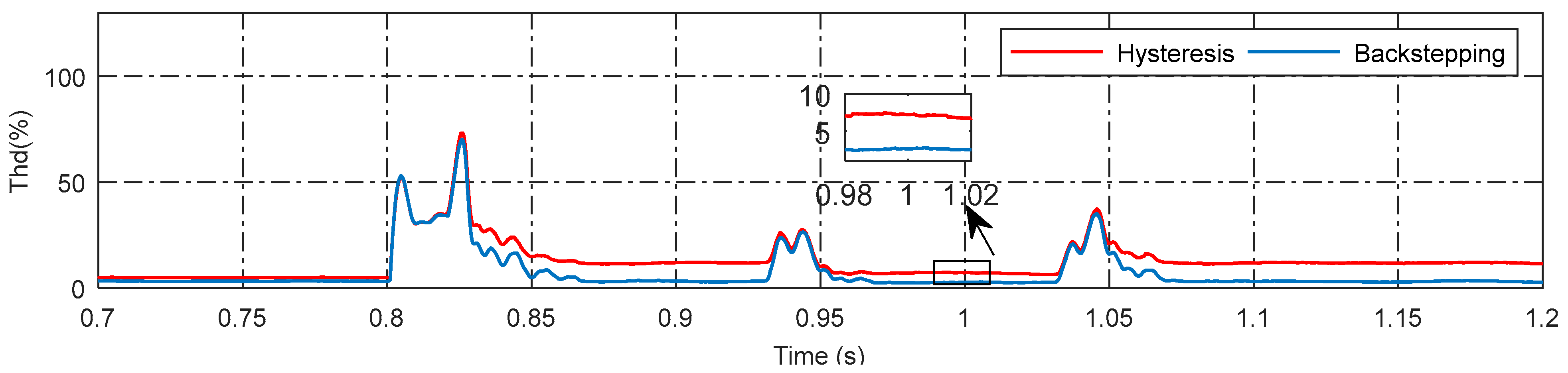
4.3. Dynamic Load Conditions
5. Conclusions
- -
- Enhancing the reliability and efficiency of the power supply by taking advantage of renewable energy sources;
- -
- Mitigating the harmonic current, which eventually decreases the source current’s ripples and enhances the overall performance of the grid;
- -
- Providing a smooth, dynamic transition between two modes, which guarantees a consistent input current waveform throughout both modes of operation.
Author Contributions
Funding
Data Availability Statement
Acknowledgments
Conflicts of Interest
References
- Cai, T.; Dong, M.; Chen, K.; Gong, T. Methods of participating power spot market bidding and settlement for renewable energy systems. Energy Rep. 2022, 8, 7764–7772. [Google Scholar] [CrossRef]
- Gajewski, P.; Pieńkowski, K. Control of the Hybrid Renewable Energy System with Wind Turbine, Photovoltaic Panels and Battery Energy Storage. Energies 2021, 14, 1595. [Google Scholar] [CrossRef]
- Khosravi, N.; Abdolmohammadi, H.R.; Bagheri, S.; Miveh, M.R. A novel control approach for harmonic compensation using switched power filter compensators in micro-grids. IET Renew. Power Gener. 2021, 15, 3989–4005. [Google Scholar] [CrossRef]
- Rekioua, D. Hybrid Renewable Energy Systems: Optimization and Power Management Control; Springer Nature: Berlin, Germany, 2019. [Google Scholar]
- Cao, B.; Dong, W.; Lv, Z.; Gu, Y.; Singh, S.; Kumar, P. Hybrid Microgrid Many-Objective Sizing Optimization with Fuzzy Decision. IEEE Trans. Fuzzy Syst. 2020, 28, 2702–2710. [Google Scholar] [CrossRef]
- Taghieh, A.; Mohammadzadeh, A.; Zhang, C.; Kausar, N.; Castillo, O. A type-3 fuzzy control for current sharing and voltage balancing in microgrids. Appl. Soft Comput. 2022, 129, 109636. [Google Scholar] [CrossRef]
- Rao, S.N.; Kumar, D.V.A.; Babu, C.S. Grid Connected Distributed Generation System with High Voltage Gain Cascaded DC-DC Converter Fed Asymmetric Multilevel Inverter Topology. Int. J. Electr. Comput. Eng. 2018, 8, 4047–4059. [Google Scholar] [CrossRef]
- Lin, X.; Wen, Y.; Yu, R.; Yu, J.; Wen, H. Improved Weak Grids Synchronization Unit for Passivity Enhancement of Grid-Connected Inverter. IEEE J. Emerg. Sel. Top. Power Electron. 2022, 10, 7084–7097. [Google Scholar] [CrossRef]
- Lin, X.; Liu, Y.; Yu, J.; Yu, R.; Zhang, J.; Wen, H. Stability analysis of Three-phase Grid-Connected inverter under the weak grids with asymmetrical grid impedance by LTP theory in time domain. Int. J. Electr. Power Energy Syst. 2022, 142, 108244. [Google Scholar] [CrossRef]
- Tareen, W.U.K.; Mekhielf, S. Three-phase transformerless shunt active power filter with reduced switch count for harmonic compensation in grid-connected applications. IEEE Trans. Power Electron. 2017, 33, 4868–4881. [Google Scholar] [CrossRef]
- Reddy, C.R.; Goud, B.S.; Aymen, F.; Rao, G.S.; Bortoni, E.C. Power quality improvement in HRES grid connected system with FOPID based atom search optimization technique. Energies 2021, 14, 5812. [Google Scholar] [CrossRef]
- Liao, K.; Pang, B.; Yang, J.; He, Z. Compensation Strategy of Wideband Voltage Harmonics for Doubly-Fed Induction Generator. IEEE Trans. Energy Convers. 2023, 38, 674–684. [Google Scholar] [CrossRef]
- Teta, A. Investigation on Active Power Filter Based on Z-Source Inverter Topology. Ph.D. Thesis, Université de Djelfa-Ziane Achour, Djelfa, Algeria, 2021. [Google Scholar]
- Liao, K.; Lu, D.; Wang, M.; Yang, J. A Low-Pass Virtual Filter for Output Power Smoothing of Wind Energy Conversion Systems. IEEE Trans. Ind. Electron. 2022, 69, 12874–12885. [Google Scholar] [CrossRef]
- Rivas, D.; Morán, L.; Dixon, J.W.; Espinoza, J.R. Improving passive filter compensation performance with active techniques. IEEE Trans. Ind. Electron. 2003, 50, 161–170. [Google Scholar] [CrossRef]
- Lee, T.-L.; Wang, Y.-C.; Li, J.-C.; Guerrero, J.M. Hybrid active filter with variable conductance for harmonic resonance suppression in industrial power systems. IEEE Trans. Ind. Electron. 2014, 62, 746–756. [Google Scholar] [CrossRef]
- Saidi, S.; Abbassi, R.; Chebbi, S. Quality improvement of shunt active power filter with direct instantaneous power estimator based on Virtual Flux. Int. J. Control. Autom. Syst. 2016, 14, 1309–1321. [Google Scholar] [CrossRef]
- Pandove, G.; Singh, M. Robust repetitive control design for a three-phase four wire shunt active power filter. IEEE Trans. Ind. Informatics 2018, 15, 2810–2818. [Google Scholar] [CrossRef]
- Cao, W.; Liu, K.; Wu, M.; Xu, S.; Zhao, J. An improved current control strategy based on particle swarm optimization and steady-state error correction for SAPF. IEEE Trans. Ind. Appl. 2019, 55, 4268–4274. [Google Scholar] [CrossRef]
- Zhai, H.; Zhuo, F.; Zhu, C.; Yi, H.; Wang, Z.; Tao, R.; Wei, T. An optimal compensation method of shunt active power filters for system-wide voltage quality improvement. IEEE Trans. Ind. Electron. 2019, 67, 1270–1281. [Google Scholar] [CrossRef]
- Teta, A.; Kouzou, A.; Rezaoui, M.M. Modeling and performance analysis of shunt active filter connected with photovoltaic system based on Z-source inverter. COMPEL-Int. J. Comput. Math. Electr. Electron. Eng. 2019, 38, 2001–2019. [Google Scholar] [CrossRef]
- Zeng, Z.; Yang, H.; Zhao, R.; Cheng, C. Topologies and control strategies of multi-functional grid-connected inverters for power quality enhancement: A comprehensive review. Renew. Sustain. Energy Rev. 2013, 24, 223–270. [Google Scholar] [CrossRef]
- Tareen, W.U.; Mekhilef, S.; Seyedmahmoudian, M.; Horan, B. Active power filter (APF) for mitigation of power quality issues in grid integration of wind and photovoltaic energy conversion system. Renew. Sustain. Energy Rev. 2017, 70, 635–655. [Google Scholar] [CrossRef]
- Ravinder, K.; Bansal, H.O. Investigations on shunt active power filter in a PV-wind-FC based hybrid renewable energy system to improve power quality using hardware-in-the-loop testing platform. Electr. Power Syst. Res. 2019, 177, 105957. [Google Scholar] [CrossRef]
- Mantilla, M.A.; Petit, J.F.; Ordoñez, G. Control of multi-functional grid-connected PV systems with load compensation under distorted and unbalanced grid voltages. Electr. Power Syst. Res. 2021, 192, 106918. [Google Scholar] [CrossRef]
- Safa, A.; Berkouk, E.M.; Messlem, Y.; Gouichiche, A. A robust control algorithm for a multifunctional grid tied inverter to enhance the power quality of a microgrid under unbalanced conditions. Int. J. Electr. Power Energy Syst. 2018, 100, 253–264. [Google Scholar] [CrossRef]
- Elnozahy, A.; Yousef, A.M.; Abo-Elyousr, F.K.; Mohamed, M.; Abdelwahab, S.A.M. Performance improvement of hybrid renewable energy sources connected to the grid using artificial neural network and sliding mode control. J. Power Electron. 2021, 21, 1166–1179. [Google Scholar] [CrossRef]
- Deng, W.; Zhang, Y.; Tang, Y.; Li, Q.; Yi, Y. A neural network-based adaptive power-sharing strategy for hybrid frame inverters in a microgrid. Front. Energy Res. 2023, 10, 1082948. [Google Scholar] [CrossRef]
- Bellia, H.; Youcef, R.; Fatima, M. A detailed modeling of photovoltaic module using MATLAB. NRIAG J. Astron. Geophys. 2014, 3, 53–61. [Google Scholar] [CrossRef]
- Marmouh, S.; Boutoubat, M.; Mokrani, L. Performance and power quality improvement based on DC-bus voltage regulation of a stand-alone hybrid energy system. Electr. Power Syst. Res. 2018, 163, 73–84. [Google Scholar] [CrossRef]
- Wu, B.; Lang, Y.; Zargari, N.; Kouro, S. Power Conversion and Control of Wind Energy Systems; John Wiley & Sons: Hoboken, NJ, USA, 2011. [Google Scholar]
- Ma, Y.; Zhu, D.; Zhang, Z.; Zou, X.; Hu, J.; Kang, Y. Modeling and Transient Stability Analysis for Type-3 Wind Turbines Using Singular Perturbation and Lyapunov Methods. IEEE Trans. Ind. Electron. 2023, 70, 8075–8086. [Google Scholar] [CrossRef]
- Cui, J.; Liu, S.; Liu, J.; Liu, X. A comparative study of MPC and economic MPC of wind energy conversion systems. Energies 2018, 11, 3127. [Google Scholar] [CrossRef]
- Amir, M.; Srivastava, S.K. Analysis of mppt based grid connected hybrid renewable energy system with battery backup. In Proceedings of the 2018 International Conference on Computing, Power and Communication Technologies (GUCON), Greater Noida, India, 28–29 September 2018; IEEE: Piscataway, NJ, USA, 2018; pp. 903–907. [Google Scholar]
- Narayana, M.; Putrus, G.; Jovanovic, M.; Leung, P.; McDonald, S. Generic maximum power point tracking controller for small-scale wind turbines. Renew. Energy 2012, 44, 72–79. [Google Scholar] [CrossRef]
- Dali, A.; Abdelmalek, S.; Bakdi, A.; Bettayeb, M. A new robust control scheme: Application for MPP tracking of a PMSG-based variable-speed wind turbine. Renew. Energy 2021, 172, 1021–1034. [Google Scholar] [CrossRef]
- Abd Rahim, N.; Selvaraj, J. Hysteresis current control and sensorless MPPT for grid-connected photovoltaic systems. In 2007 IEEE International Symposium on Industrial Electronics; IEEE: Piscataway, NJ, USA, 2007; pp. 572–577. [Google Scholar]
- Al-Shetwi, A.Q.; Hannan, M.A.; Jern, K.P.; Alkahtani, A.A.; PGAbas, A.E. Power quality assessment of grid-connected PV system in compliance with the recent integration requirements. Electronics 2020, 9, 366. [Google Scholar] [CrossRef]
- Varaprasad, O.V.S.R.; Kumar, D.B.; Sarma, D.V.S.S.S. Three level hysteresis current controlled vsi for power injection and conditioning in grid connected solar pv systems. In Proceedings of the 2014 IEEE International Conference on Power Electronics, Drives and Energy Systems (PEDES), Mumbai, India, 16–19 December 2014; IEEE: Piscataway, NJ, USA, 2014; pp. 1–5. [Google Scholar]
- Wai, R.-J.; Yang, Y. Design of backstepping direct power control for three-phase PWM rectifier. IEEE Trans. Ind. Appl. 2019, 55, 3160–3173. [Google Scholar] [CrossRef]
- Youness, E.M.; Aziz, D.; Abdelaziz, E.G.; Jamal, B.; Najib, E.O.; Othmane, Z.; Khalid, M.; Bossoufi, B. Implementation and validation of backstepping control for PMSG wind turbine using DSPACE controller board. Energy Rep. 2019, 5, 807–821. [Google Scholar] [CrossRef]
- El Mourabit, Y.; Derouich, A.; El Ghzizal, A.; El Ouanjli, N.; Zamzoum, O. Nonlinear backstepping control for PMSG wind turbine used on the real wind profile of the Dakhla-Morocco city. Int. Trans. Electr. Energy Syst. 2020, 30, e12297. [Google Scholar] [CrossRef]
- Hoon, Y.; Mohd Radzi, M.A.; Hassan, M.K.; Mailah, N.F. DC-link capacitor voltage regulation for three-phase three-level inverter-based shunt active power filter with inverted error deviation control. Energies 2016, 9, 533. [Google Scholar] [CrossRef]
- Barik, P.K.; Shankar, G.; Sahoo, P.K. Power quality assessment of microgrid using fuzzy controller aided modified SRF based designed SAPF. Int. Trans. Electr. Energy Syst. 2020, 30, e12289. [Google Scholar] [CrossRef]
- Ali, T.; Mohamed Mounir, R.; Abdellah, K. Comparative Study of Different Control Strategies for Three-Phase Shunt Active Power Filter. In Proceedings of the 2018 IEEMA Engineer Infinite Conference (eTechNxT), New Delhi, India, 13–14 March 2018. [Google Scholar]


| Parameters | Value | |
|---|---|---|
| Grid voltage (Vs) | 400 V | |
| System frequency (f) | 50 Hz | |
| Supply inductance | 20 µH | |
| Supply resistance | 0.3 Ω | |
| DC link capacitor | 5000 µF | |
| Wind system | Maximum wind power | 6 kW |
| PMSG stator phase resistance (Rs) | 0.425 Ω | |
| PMSG armature inductance Ld = Lq | 8.4 × 10⁻³ H; | |
| Leakage flux | 0.433 Wb | |
| No. of poles | 5 | |
| PV system | Maximum PV power | 5.5 kW |
| No. of series cells Ns | 9 | |
| No. of parallel cells Np | 2 |
| MPPT Efficiency | ||
|---|---|---|
| PV system | 99.45% | |
| Wind system | 98.03% | |
| Mode 01: Power injection | ||
| Backstepping | Hysteresis | |
| THD of source current | 1.44% | 2.45% |
| Active power oscillations | low | high |
| Mode 02: Power improvement | ||
| Backstepping | Hysteresis | |
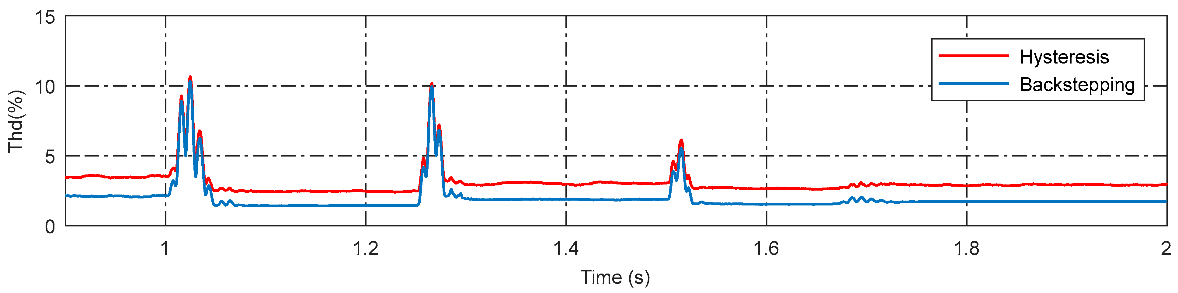
| THD of Nonlinear load | 3.22% | 12% |
| THD of Dynamic load | 2.62% | 7.24% |
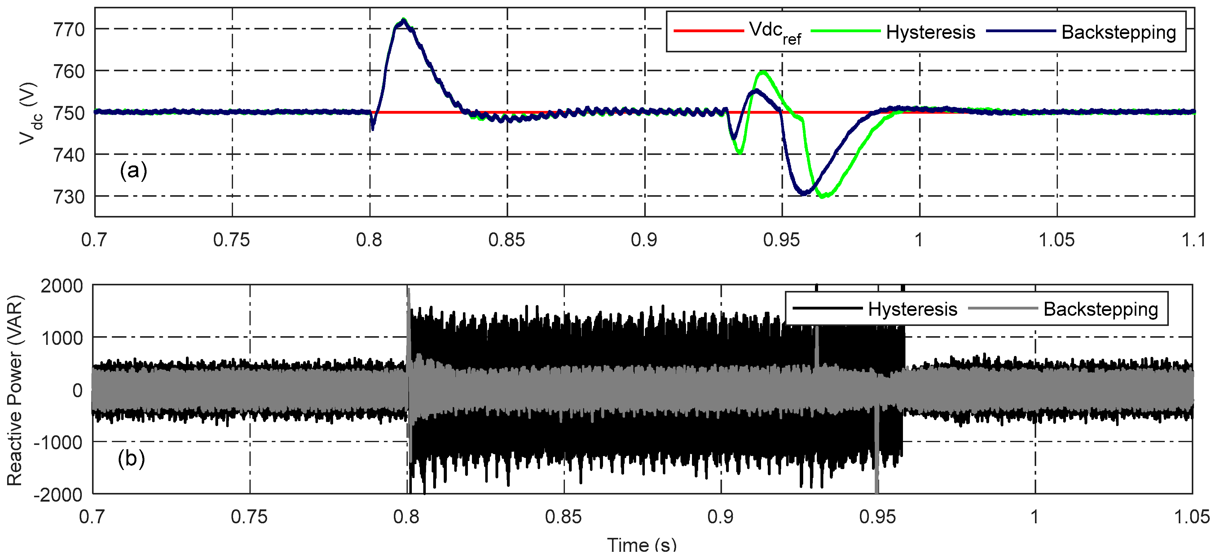
| Reactive power compensation | 97.14% | 84.28% |
Disclaimer/Publisher’s Note: The statements, opinions and data contained in all publications are solely those of the individual author(s) and contributor(s) and not of MDPI and/or the editor(s). MDPI and/or the editor(s) disclaim responsibility for any injury to people or property resulting from any ideas, methods, instructions or products referred to in the content. |
© 2023 by the authors. Licensee MDPI, Basel, Switzerland. This article is an open access article distributed under the terms and conditions of the Creative Commons Attribution (CC BY) license (https://creativecommons.org/licenses/by/4.0/).
Share and Cite
Boulanouar, S.A.; Kaddouri, A.M.; Kouzou, A.; Benaissa, A.; Teta, A.; Hafaifa, A.; Kennel, R.; Abdelrahem, M. Multifunctional Control Technique for Grid-Tied Hybrid Distributed Generation System Taking into Account Power Quality Issues. Energies 2023, 16, 6565. https://doi.org/10.3390/en16186565
Boulanouar SA, Kaddouri AM, Kouzou A, Benaissa A, Teta A, Hafaifa A, Kennel R, Abdelrahem M. Multifunctional Control Technique for Grid-Tied Hybrid Distributed Generation System Taking into Account Power Quality Issues. Energies. 2023; 16(18):6565. https://doi.org/10.3390/en16186565
Chicago/Turabian StyleBoulanouar, Sohaib Abdeslam, Ameur Miloud Kaddouri, Abdellah Kouzou, Amar Benaissa, Ali Teta, Ahmed Hafaifa, Ralph Kennel, and Mohamed Abdelrahem. 2023. "Multifunctional Control Technique for Grid-Tied Hybrid Distributed Generation System Taking into Account Power Quality Issues" Energies 16, no. 18: 6565. https://doi.org/10.3390/en16186565
APA StyleBoulanouar, S. A., Kaddouri, A. M., Kouzou, A., Benaissa, A., Teta, A., Hafaifa, A., Kennel, R., & Abdelrahem, M. (2023). Multifunctional Control Technique for Grid-Tied Hybrid Distributed Generation System Taking into Account Power Quality Issues. Energies, 16(18), 6565. https://doi.org/10.3390/en16186565