

Pressure Monitoring in Medium-Voltage Vacuum Interrupters


Abstract
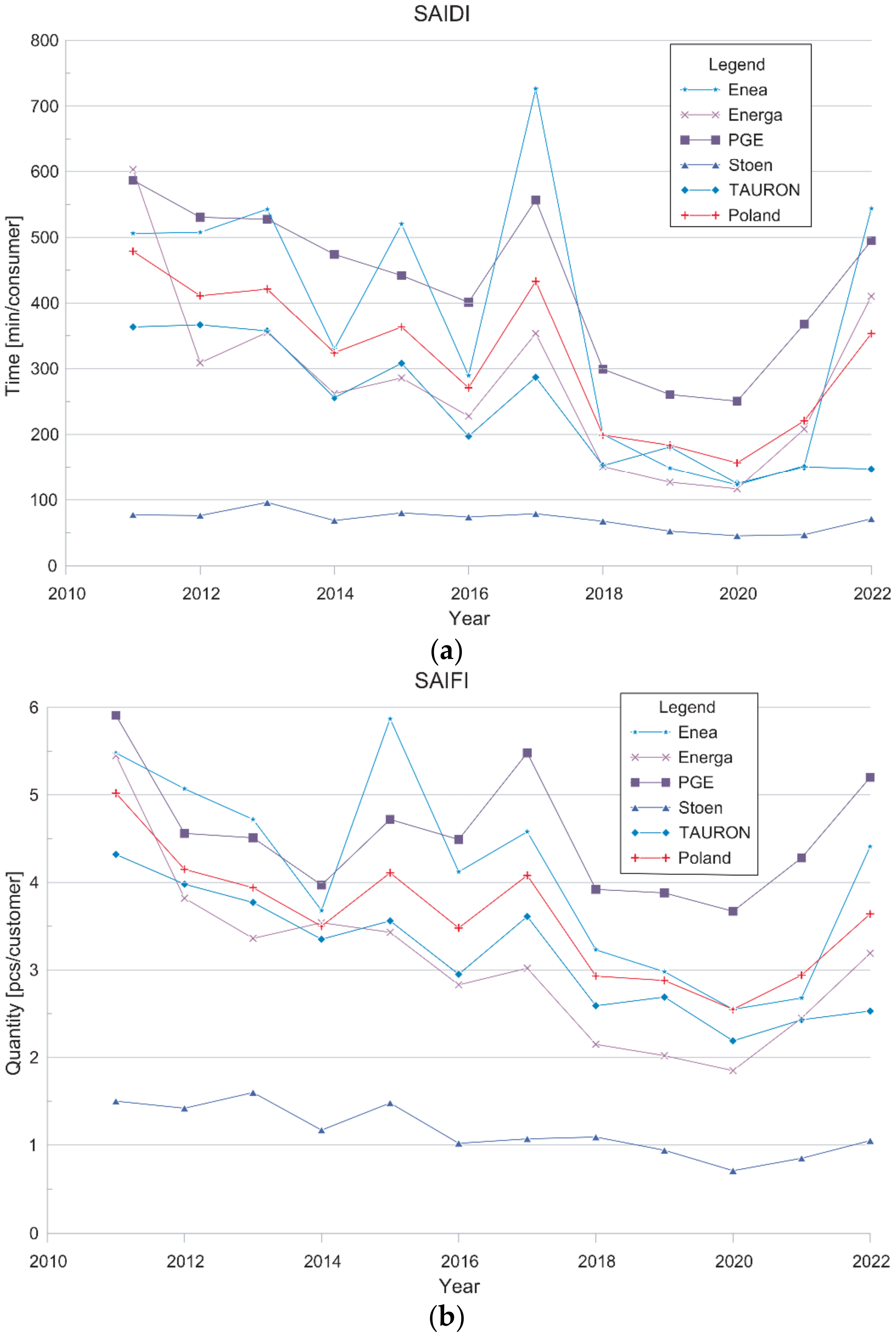
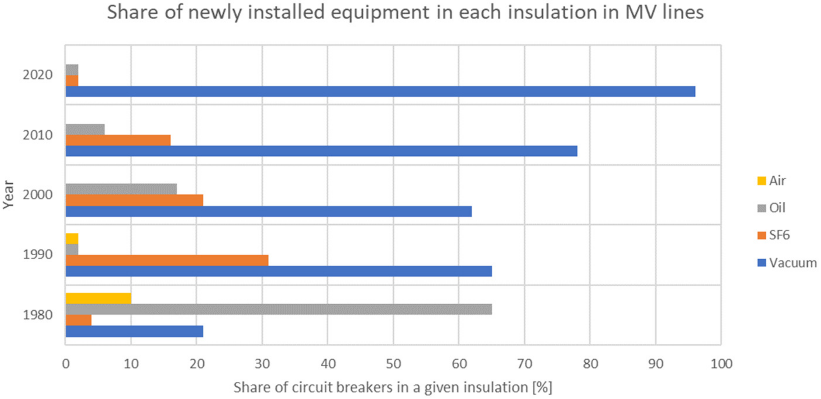
:1. Introduction
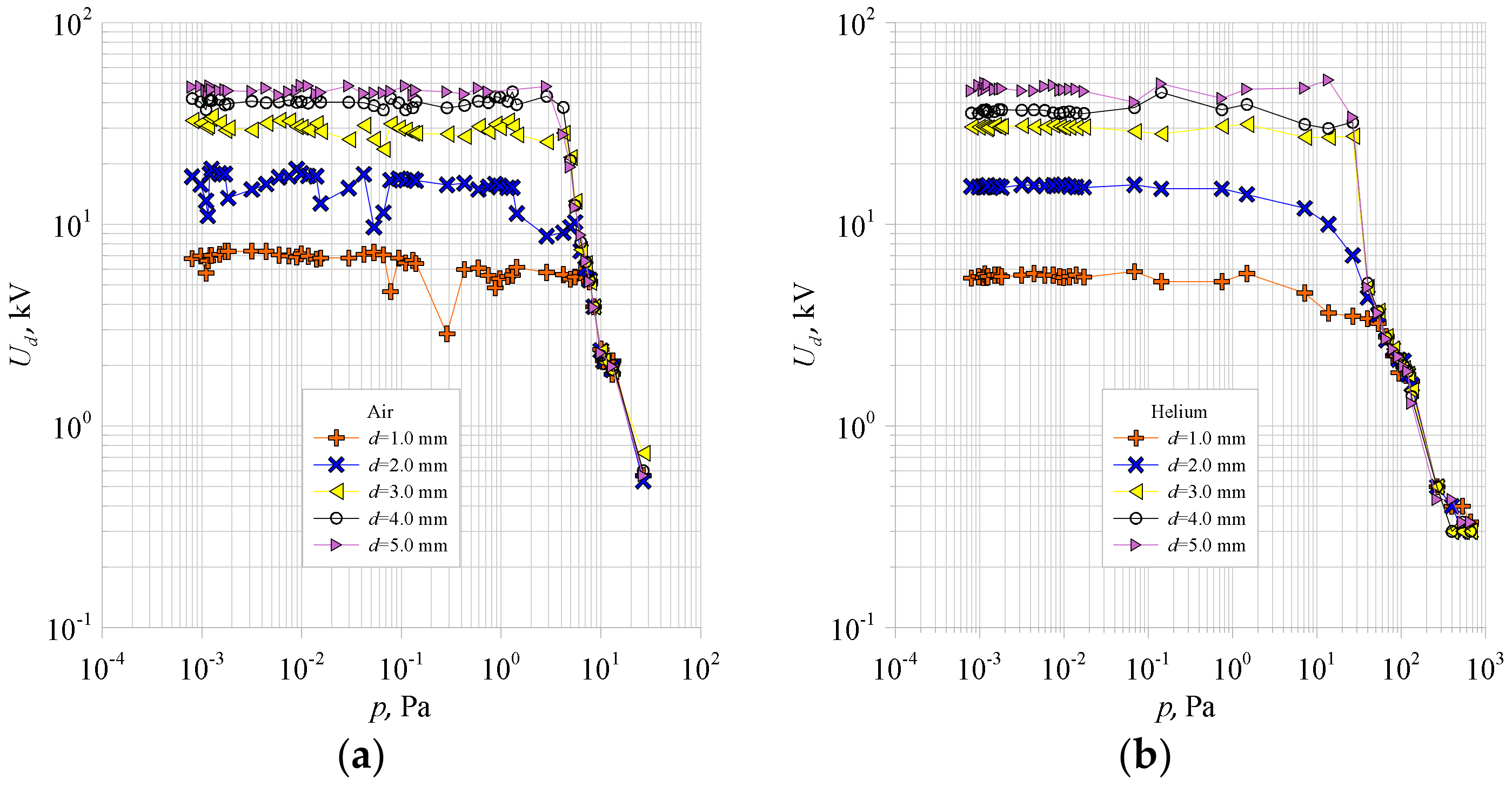
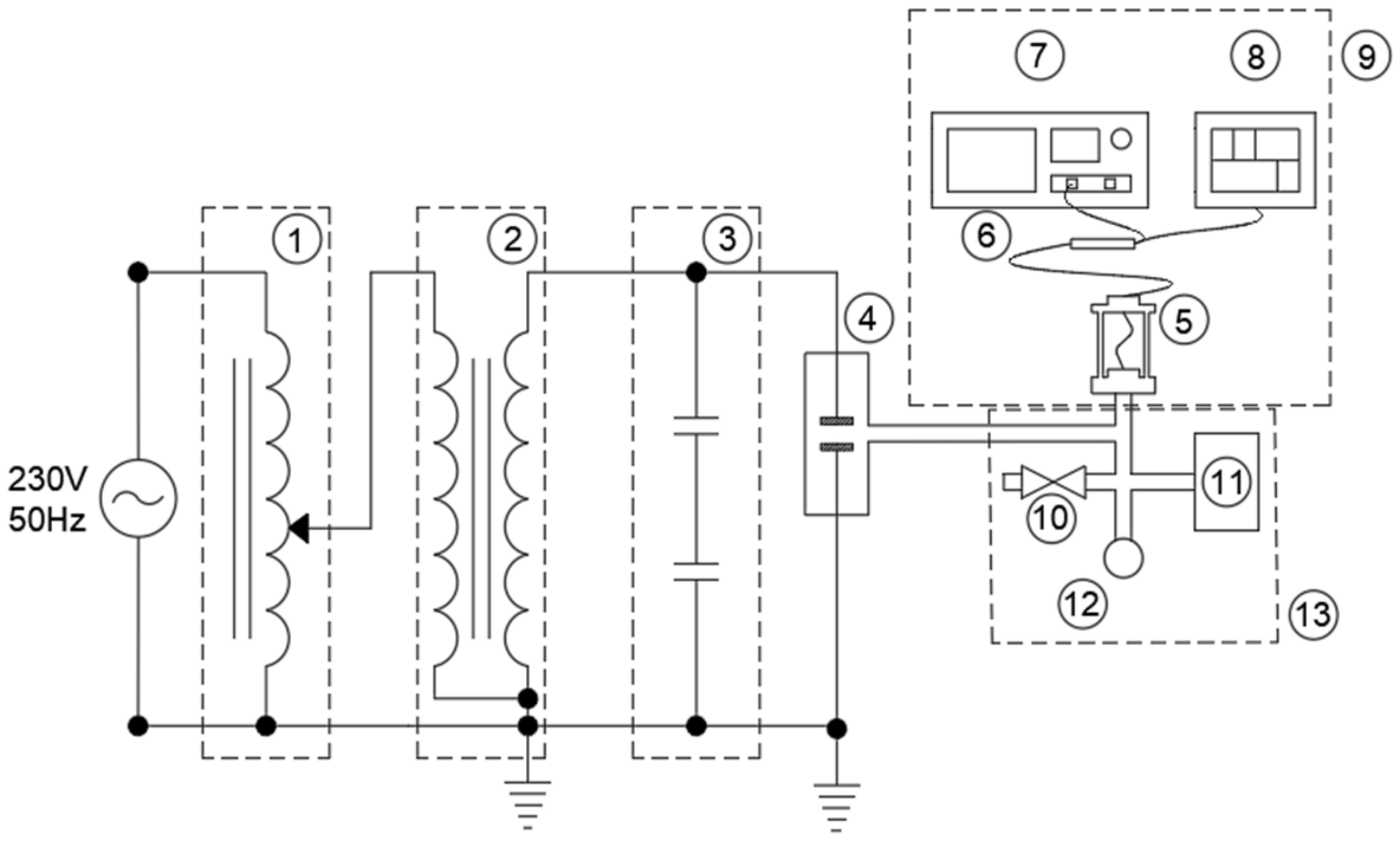
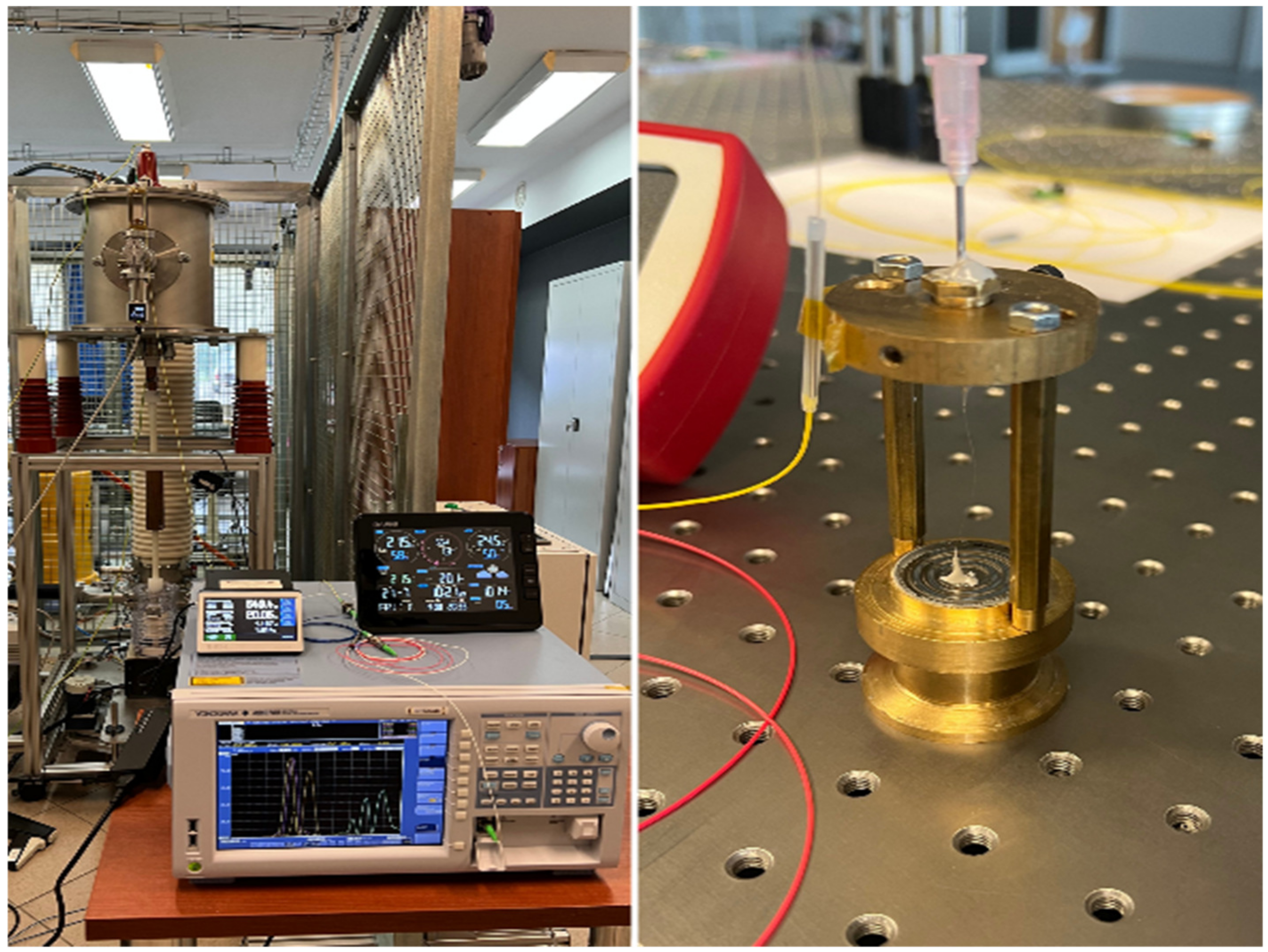
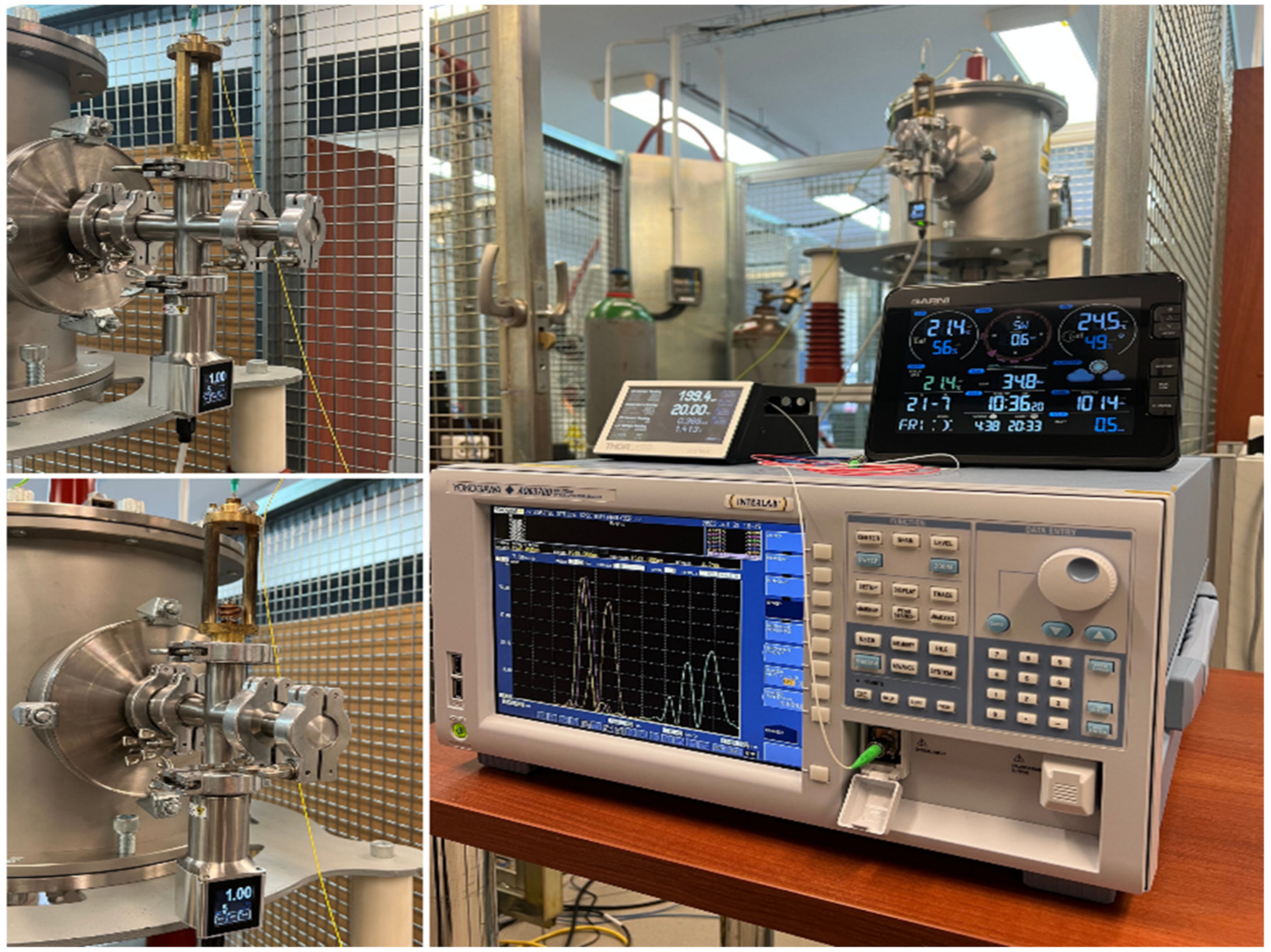
2. Research Stands, Materials, and Methods
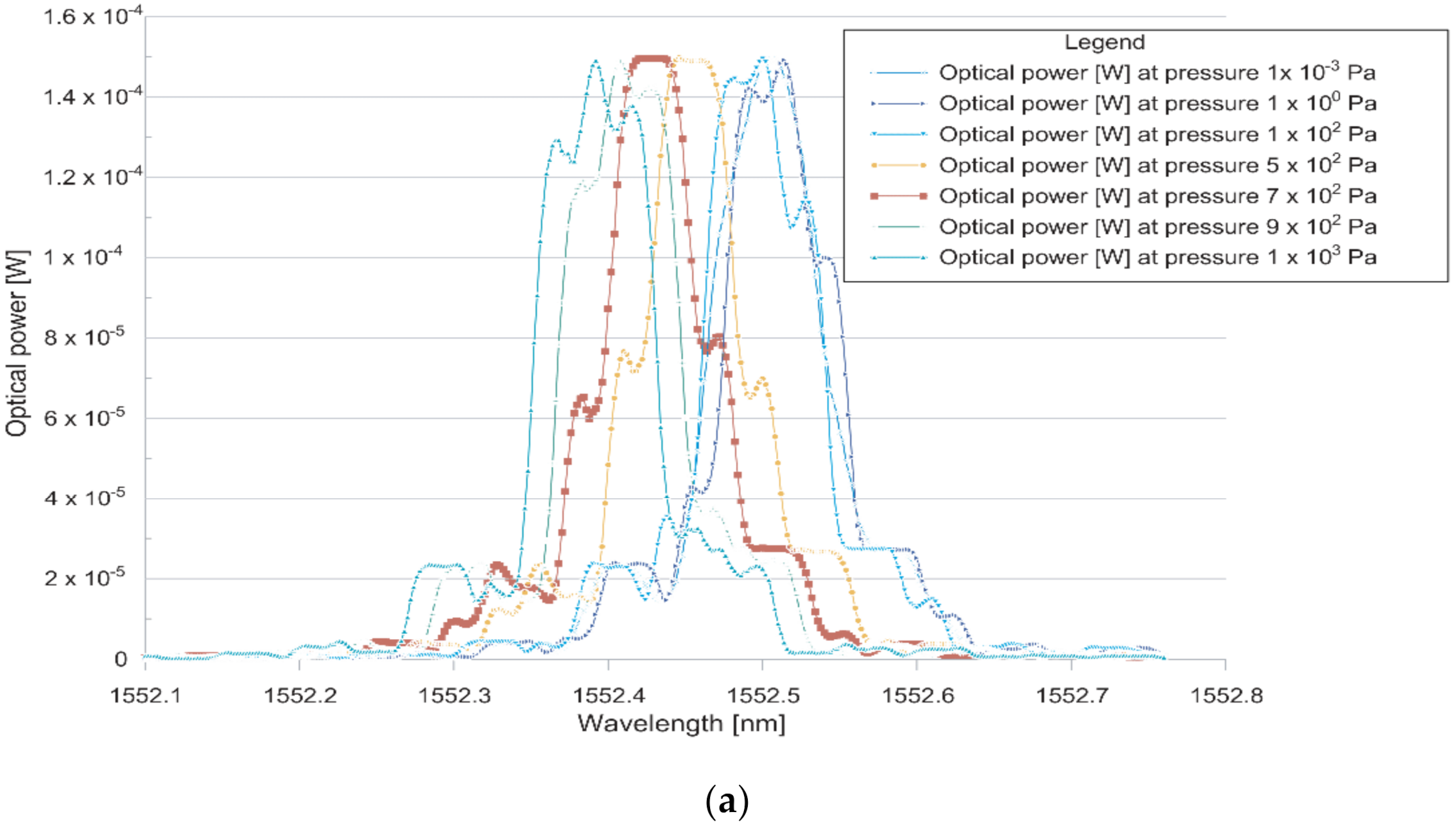
3. Test of the Measuring Head with a Spring Membrane
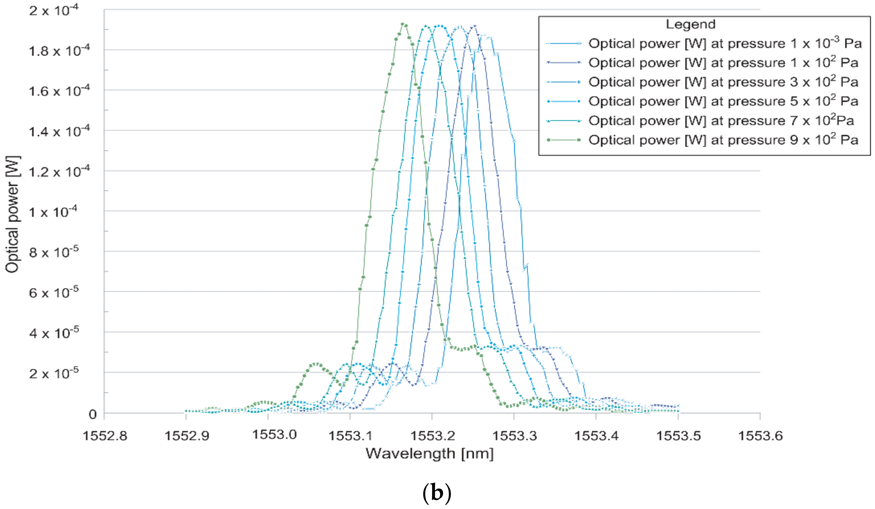
4. Testing of the Measuring Head with Elastic Bellows
5. Summary
Author Contributions
Funding
Data Availability Statement
Acknowledgments
Conflicts of Interest
References
- Polish Power Transmission and Distribution Association (PTPiREE)—Report 2022. 2023. Available online: http://www.ptpiree.pl/raporty/2023/ptpiree_raport_2023.pdf (accessed on 10 July 2023).
- Peter, G.; Stonier, A.A.; Gupta, P.; Gavilanes, D.; Vergara, M.M.; Lung sin, J. Smart Fault Monitoring and Normalizing of a Power Distribution System Using IoT. Energies 2022, 15, 8206. [Google Scholar] [CrossRef]
- Gupta, P.; Chhabra, J. IoT based Smart Home design using power and security management. In Proceedings of the 2016 International Conference on Innovation and Challenges in Cyber Security (ICICCS-INBUSH), Greater Noida, India, 3–5 February 2016; pp. 6–10. [Google Scholar] [CrossRef]
- Slade, P.G. The Vacuum Interrupter, 2nd ed.; CRC Press: Boca Raton, FL, USA, 2020. [Google Scholar] [CrossRef]
- European Parliament and of the Council. Regulation of the European Parliament and of the Council on Fluorinated Greenhouse Gases. 2022. Available online: https://eur-lex.europa.eu/legal-content/EN/TXT/HTML/?uri=CELEX:52022PC0150 (accessed on 14 July 2023).
- Węgierek, P.; Lech, M.; Kostyła, D.; Kozak, C. Study on the Effect of Helium on the Dielectric Strength of Medium-Voltage Vacuum Interrupters. Energies 2021, 14, 3742. [Google Scholar] [CrossRef]
- Chmielak, W. Review of methods of diagnostics of the vacuum in vacuum circuit breakers. Prz. Elektrotech. 2014, 2, 213–216. [Google Scholar] [CrossRef]
- Liang, M.-F.; Fang, X.-Q.; Wu, G.; Xue, G.-Z.; Li, H.-W. A Fiber Bragg Grating Pressure Sensor with Temperature Compensation Based on Diaphragm-Antilever Structure. Optik 2017, 145, 503–512, ISSN 0030-4026. [Google Scholar] [CrossRef]
- Mihailov, S.J. Fiber Bragg Grating Sensors for Harsh Environments. Sensors 2012, 12, 1898–1918. [Google Scholar] [CrossRef]
- Yang, L.; Li, C.; Luo, C. Thermal Strain Detection for Concrete Structure Cold Shrinkage under Stress Constraint with FBG. Sensors 2022, 22, 9660. [Google Scholar] [CrossRef]
- Lao, J.; Wang, C.; Tang, Y.; Zheng, P.; Wan, L.; Chan, C.C.; Ruan, S. Liquid Pressure Sensor Based on Fiber Bragg Grating with an Adjustable Structure. Sensors 2022, 22, 9188. [Google Scholar] [CrossRef]
- Węgierek, P.; Kostyła, D.; Lech, M. Directions of Development of Diagnostic Methods of Vacuum Medium-Voltage Switchgear. Energies 2023, 16, 2087. [Google Scholar] [CrossRef]
- Leal-Junior, A.G.; Díaz, C.A.R.; Frizera, A.; Marques, C.; Ribeiro, M.R.N.; Pontes, M.J. Simultaneous measurement of pressure and temperature with a single FBG embedded in a polymer diaphragm. Opt. Laser Technol. 2019, 112, 77–84. [Google Scholar] [CrossRef]
- Leal-Junior, A.; Campos, V.; Frizera, A.; Marques, C. Low-cost and high-resolution pressure sensors using highly stretchable polymer optical fibers. Mater. Lett. 2020, 271, 127810. [Google Scholar] [CrossRef]
- Leal-Junior, A.; Frizera, A.; Marques, C. A fiber Bragg gratings pair embedded in a polyurethane diaphragm: Towards a temperature-insensitive pressure sensor. Opt. Laser Technol. 2020, 131, 106440. [Google Scholar] [CrossRef]
- Ishikawa, R.; Lee, H.; Lacraz, A.; Theodosiou, A.; Kalli, K.; Mizuno, Y.; Nakamura, K. Pressure Dependence of Fiber Bragg Grating Inscribed in Perfluorinated Polymer Fiber. IEEE Photonics Technol. Lett. 2017, 29, 2167–2170. [Google Scholar] [CrossRef]
- Zhang, Q.; Wang, Y.; Sun, Y.; Gao, L.; Zhang, Z.; Zhang, W.; Zhao, P.; Yue, Y. Using Custom Fiber Bragg Grating-Based Sensors to Monitor Artificial Landslides. Sensors 2016, 16, 1417. [Google Scholar] [CrossRef] [PubMed]
- Luo, Y.-T.; Wang, H.-B.; Ma, G.-M.; Song, H.-T.; Li, C.; Jiang, J. Research on High Sensitive D-Shaped FBG Hydrogen Sensors in Power Transformer Oil. Sensors 2016, 16, 1641. [Google Scholar] [CrossRef] [PubMed]
- He, X.; Ma, C.; Wang, X.; Wang, Z.; Yuan, L. Pressure vector sensor based on an orthogonal optical path Sagnac interferometer. Opt. Express 2020, 28, 7969. [Google Scholar] [CrossRef]
- Paixão, T.; Araújo, F.; Antunes, P. Highly sensitive fiber optic temperature and strain sensor based on an intrinsic Fabry–Perot interferometer fabricated by a femtosecond laser. Opt. Lett. 2019, 44, 4833. [Google Scholar] [CrossRef]
- Qi, Y.; Zhang, J.; Feng, Q.; Zhang, X.; Liu, Y.; Han, Y. A Novel High Sensitivity Refractive Index Sensor Based on Multi-Core Micro/Nano Fiber. Photonic Sens. 2019, 9, 197–204. [Google Scholar] [CrossRef]
- Lin, H.; Liu, F.; Guo, H.; Zhou, A.; Dai, Y. Ultra-highly sensitive gas pressure sensor based on dual side-hole fiber interferometers with Vernier effect. Opt. Express 2018, 26, 28763. [Google Scholar] [CrossRef]
- Ma, C.; Peng, D.; Bai, X.; Liu, S.; Luo, L. A Review of Optical Fiber Sensing Technology Based on Thin Film and Fabry–Perot Cavity. Coatings 2023, 13, 1277. [Google Scholar] [CrossRef]
- Li, J.; Fang, L.; Sun, B.; Li, X.; Kang, S.H. Review—Recent Progress in Flexible and Stretchable Piezoresistive Sensors and Their Applications. J. Electrochem. Soc. 2020, 167, 037561. [Google Scholar] [CrossRef]
- Wang, W.; Li, F. Large-range liquid level sensor based on an optical fiber extrinsic Fabry–Perot interferometer. Opt. Lasers Eng. 2014, 52, 201–205. [Google Scholar] [CrossRef]
- Pan, R.; Yang, W.; Li, L.; Yang, Y.; Yu, X.; Fan, J.; Yu, S.; Xiong, Y.; Zhang, L. High-sensitive fiber-optic pressure sensor based on Fabry-Perot interferometer filled with ultraviolet glue film and Vernier effect. Opt. Fiber Technol. 2021, 67, 102710. [Google Scholar] [CrossRef]
- Guo, X.; Ye, W.; Jiang, C.; Sun, S. High sensitivity gas pressure sensor based on two parallel-connected Fabry–Perot interferometers and Vernier effect. Meas. Sci. Technol. 2021, 32, 125124. [Google Scholar] [CrossRef]
- Chen, P.; Dai, Y.; Zhang, D.; Wen, X.; Yang, M. Cascaded-Cavity Fabry-Perot Interferometric Gas Pressure Sensor based on Vernier Effect. Sensors 2018, 18, 3677. [Google Scholar] [CrossRef]
- Wang, J.; Li, L.; Liu, S.; Wu, D.; Wang, W.; Song, M.; Wang, G.; Huang, M. Investigation of Composite Structure with Dual Fabry–Perot Cavities for Temperature and Pressure Sensing. Photonics 2021, 8, 138. [Google Scholar] [CrossRef]
- Liao, C.; Liu, S.; Xu, L.; Wang, C.; Wang, Y.; Li, Z.; Wang, Q.; Wang, D.N. Sub-micron silica diaphragm-based fiber-tip Fabry–Perot interferometer for pressure measurement. Opt. Lett. 2014, 39, 2827. [Google Scholar] [CrossRef]
- Hou, M.; Zhu, F.; Wang, Y.; Liao, C.; Liu, S.; Lu, P. Antiresonant reflecting guidance mechanism in hollow-core fiber for gas pressure sensing. Opt. Express 2016, 24, 27890. [Google Scholar] [CrossRef]
- Tang, J.; Yin, G.; Liao, C.; Liu, S.; Li, Z.; Zhong, X.; Wang, Q.; Zhao, J.; Yang, K.; Wang, Y. High-Sensitivity Gas Pressure Sensor Based on Fabry–Pérot Interferometer with a Side-Opened Channel in Hollow-Core Photonic Bandgap Fiber. IEEE Photonics J. 2015, 7, 1–7. [Google Scholar] [CrossRef]
- Song, X.; Hou, L.; Wei, X.; Su, H.; Li, C.; Li, Y.; Ran, L. High Sensitivity Fiber Gas Pressure Sensor with Two Separated Fabry–Pérot Interferometers Based on the Vernier Effect. Photonics 2022, 9, 31. [Google Scholar] [CrossRef]
- Liu, T.; Zhang, W.; Wang, S.; Jiang, J.; Liu, K.; Wang, X.; Zhang, J. Temperature Insensitive and Integrated Differential Pressure Sensor for Liquid Level Sensing Based on an Optical Fiber Fabry–Perot Interferometer. IEEE Photonics J. 2018, 10, 1–8. [Google Scholar] [CrossRef]
- Klimek, J.; Kisała, P.; Cięszczyk, S. Badanie Wpływu Parametrów Procesu Wytwarzania Periodycznych Struktur Światłowodowych na ich Charakterystyki Widmowe. Kraków. 2021. Available online: https://www.eaiib.agh.edu.pl/wp-content/uploads/2021/06/autoreferat-Klimek-Jacek.pdf (accessed on 23 July 2023).
- Xu, M.G.; Reekie, L.; Chow, Y.T.; Dakin, J.P. Optical in-fiber grating high pressure sensor. Electron. Lett. 1993, 29, 398–399. [Google Scholar] [CrossRef]
- Huang, J.; Zhou, Z.; Zhang, D.; Wei, Q. A Fiber Bragg Grating Pressure Sensor and Its Application to Pipeline Leakage Detection. Adv. Mech. Eng. 2013, 5, 590451. [Google Scholar] [CrossRef]
- Huang, J.; Zhou, Z.; Wen, X.; Zhang, D. A diaphragm-type fiber Bragg grating pressure sensor with temperature compensation. Measurement 2013, 46, 1041–1046. [Google Scholar] [CrossRef]
- Węgierek, P.; Lech, M.; Kozak, C.; Pastuszak, J. Methodology for testing the electric strength of vacuum chambers designed for modern medium voltage switchgear. Metrol. Meas. Syst. 2020, 27, 687–700. [Google Scholar] [CrossRef]
- Lech, M.; Węgierek, P. Breakdown Initiation and Electrical Strength of a Vacuum Insulating System in the Environment of Selected Noble Gases at AC Voltage. Energies 2022, 15, 1154. [Google Scholar] [CrossRef]
- Węgierek, P.; Lech, M. Test stand for testing and diagnostics of medium voltage vacuum interrupters. Prz. Elektrotech. 2021, 97, 176–179. [Google Scholar] [CrossRef]
- Lech, M.; Węgierek, P.; Kostyła, D. Laboratory studies of the electrical strength of vacuum obtained on the basis of air, neon and helium. Prz. Elektrotech. 2022, 1, 117–120. [Google Scholar] [CrossRef]


| No | Pressure [Pa] | Membrane Deflection [mm] | |
|---|---|---|---|
| Stainless Steel | INCOTEL 718 | ||
| 1 | 6.89 | 2.0 × 10⁻⁵ | 9.0 × 10⁻⁵ |
| 2 | 68.95 | 5.0 × 10⁻⁵ | 1.0 × 10⁻⁴ |
| 3 | 689.48 | 3.0 × 10⁻⁴ | 3.0 × 10⁻⁴ |
| 4 | 2757.92 | 1.3 × 10⁻³ | 1.2 × 10⁻³ |
| 5 | 4826.36 | 2.3 × 10⁻³ | 2.2 × 10⁻³ |
| 6 | 6894.80 | 3.3 × 10⁻³ | 3.1 × 10⁻³ |
| 7 | 34474.00 | 1.56 × 10⁻² | 1.38 × 10⁻² |
| No | Material | Outer Diameter | Inside Diameter | Effective Area | Number of Coils | Length of the Coil Area | Coefficient of Elasticity | Maximum Deflection | Maximum Working Pressure | Wall Thickness |
|---|---|---|---|---|---|---|---|---|---|---|
| mm | mm | cm3 | - | mm | N/m | mm | MPa | mm | ||
| 1 | Bronze and Brass | 22.00 | 15.00 | 2.69 | 9.00 | 15.00 | 8.30 | 4.50 | 0.10 | 0.13 |
| 2 | 12.00 | 8.00 | 0.80 | 19.00 | 29.50 | - | 9.16 | 1.80 | 0.11 | |
| 3 | 10.00 | 6.00 | 0.50 | 28.00 | 31.00 | 3.00 | 8.00 | 2.00 | 0.10 | |
| 4 | 12.00 | 8.00 | 0.80 | 18.00 | 22.20 | - | 6.00 | 1.80 | 0.11 | |
| 5 | 16.00 | 10.50 | 1.61 | 6.00 | 8.40 | 9.00 | 3.00 | 0.65 | 0.10 | |
| 6 | Stainless steel | 7.00 | 4.65 | 0.27 | 12.00 | 12.30 | 55.00 | 1.90 | 18.00 | 0.10 |
| 7 | 38.10 | 25.00 | 7.93 | 13.00 | 41.17 | 1.90 | 13.70 | 0.35 | 0.13 | |
| 8 | 13.20 | 9.40 | 1.01 | 13.00 | 14.20 | 19.00 | 3.90 | 3.00 | 0.10 | |
| 9 | Monel400 | 50.80 | 34.67 | 14.34 | 14.00 | 47.60 | 5.00 | 9.00 | 0.20 | 0.18 |
| No | Type of Head | Measuring Range [Pa] | Operational Use | Determination of Pressure Values | Repeatability |
|---|---|---|---|---|---|
| 1 | Head with stainless steel membrane | 5 × 10²–1 × 10⁵ | Yes | Yes | 95.88% |
| 2 | Head with INCOTEL 718 membrane | 1 × 10²–1 × 10⁵ | Yes | Yes | 96.80% |
| 3 | Head with compression bellows | 1 × 10²–1 × 10⁵ | Yes | Yes | 98.56% |
| 4 | Head with extension bellows | 2 × 101–1 × 10⁵ | Yes | Yes | 98.77% |
Disclaimer/Publisher’s Note: The statements, opinions and data contained in all publications are solely those of the individual author(s) and contributor(s) and not of MDPI and/or the editor(s). MDPI and/or the editor(s) disclaim responsibility for any injury to people or property resulting from any ideas, methods, instructions or products referred to in the content. |
© 2023 by the authors. Licensee MDPI, Basel, Switzerland. This article is an open access article distributed under the terms and conditions of the Creative Commons Attribution (CC BY) license (https://creativecommons.org/licenses/by/4.0/).
Share and Cite
Węgierek, P.; Kostyła, D.; Lech, M.; Kozak, C.; Zielonka, A. Pressure Monitoring in Medium-Voltage Vacuum Interrupters. Energies 2023, 16, 6562. https://doi.org/10.3390/en16186562
Węgierek P, Kostyła D, Lech M, Kozak C, Zielonka A. Pressure Monitoring in Medium-Voltage Vacuum Interrupters. Energies. 2023; 16(18):6562. https://doi.org/10.3390/en16186562
Chicago/Turabian StyleWęgierek, Paweł, Damian Kostyła, Michał Lech, Czesław Kozak, and Alicja Zielonka. 2023. "Pressure Monitoring in Medium-Voltage Vacuum Interrupters" Energies 16, no. 18: 6562. https://doi.org/10.3390/en16186562
APA StyleWęgierek, P., Kostyła, D., Lech, M., Kozak, C., & Zielonka, A. (2023). Pressure Monitoring in Medium-Voltage Vacuum Interrupters. Energies, 16(18), 6562. https://doi.org/10.3390/en16186562