Article

Proposal for Repairable Silicon Solar Panels: Proof of Concept

1
Faculty of Engineering, Ain-Shams University, Cairo 11535, Egypt
2
Electronics and Electrical Communication Department, Ain-Shams University, Cairo 11535, Egypt
3
Engineering Physics and Mathematics Department, Ain-Shams University, Cairo 11535, Egypt
4
Electrical Engineering Department, Future University in Egypt, Cairo 11835, Egypt
*
Author to whom correspondence should be addressed.
Energies 2023, 16(18), 6492; https://doi.org/10.3390/en16186492
Submission received: 17 May 2023 / Revised: 11 July 2023 / Accepted: 4 August 2023 / Published: 8 September 2023
(This article belongs to the Section A2: Solar Energy and Photovoltaic Systems)

Abstract

:
The long-term performance of traditional solar panels can be affected by various climate conditions, resulting in issues such as decreased power output, interconnector failure, and cell fracture. Unfortunately, traditional modules are not repairable, and often the entire unit must be replaced, even if the failure is due only to a single component. In this work, conventional encapsulation methods are investigated, and a novel solar panel design approach is introduced. This innovative approach enables easy and direct access to individual components, thereby enabling the convenient carrying out of repairs, upgrades, and modifications. The proposed module configuration is composed of a double-layer structure. The initial layer functions as a protective glass cover while the second layer is made up of solar cells that are attached to a printed circuit board (PCB) that can endure high temperatures. These two layers are combined within an aluminum frame that can be opened for accessibility. To test the effectiveness of this new encapsulation technique, an experimental study was conducted. It was revealed through this experimental study that the dark and illuminated current–voltage characteristics are not affected when applying the new encapsulation technique. Furthermore, a theoretical thermal analysis was conducted in order to compare the performance of the proposed module with that of a conventional module. According to the thermal analysis, the proposed encapsulation method should result in slightly higher thermal stress on the solar cells compared with conventional encapsulation. Nonetheless, the proposed methodology offers advantages in terms of reliability and reparability. Thus, implementing the presented design can help conserve natural resources and reduce production costs.

1. Introduction

Solar energy is a highly beneficial renewable energy source due to its widespread availability, its reliability, its efficiency, and the lack of pollution it produces [1]. In accordance with the global effort to increase the use of clean energy resources, the utilization and market potential of photovoltaic (PV) energy has grown significantly in recent years [2]. A typical PV system consists of three main parts: the solar array, storage batteries, and inverter. The solar array, which is made up of interconnected solar panels or modules, is designed to meet the power requirements of the load [3]. The encapsulation process is crucial in providing mechanical rigidity and environmental protection to the solar cell matrix [4]. However, it is important to note that once encapsulation is complete, the solar cells and connections become a monolithic structure, rendering modifications to the cells or connections impossible.
Notably, there are three generations of solar panels: monocrystalline or multi-crystalline silicon, thin film, and concentrator PVs. The most popular commercial solar panel material is currently crystalline silicon; it is used to make monocrystalline and polycrystalline panels, which offer greater conversion efficiencies than thin film panels [5]. A typical solar panel consists of several key parts, including a frame made of an aluminum alloy (Al), tempered glass, a junction box, EVA (ethylene/vinyl acetate copolymer), and a backboard [5].
The solar module may be affected by several common issues, such as cell cracking, reductions in output power, EVA discoloration, delamination of the EVA from the solar cells, and interconnection breakage leading to open circuit defects [6]. Unfortunately, once a solar module is damaged, it cannot be repaired, even if the problem originated from a simple and inexpensive component. To address this issue, there is a need to develop a new module structure that enables the easy the repair and maintenance of individual components, as well as the potential for module expansion [7].
In this work, we propose a novel case module that can overcome these shortcomings by enabling the repair or upgrade of the solar panel. The new module design comprises two layers: the first layer is a protective glass layer, and the second layer consists of solar cells adhered to a printed circuit board capable of withstanding high temperatures. The two layers are separated by an air gap, achieved by using rubber at the edges of the module, and are assembled within an aluminum frame that can be easily opened. Due to the significant impact of temperature on PV system efficiency and output power [8], it is essential to perform a thermal analysis of any new module design and compare it with a traditional module. In the proposed approach, the aim is to minimize the air gap between the two layers to prevent excessive cell temperatures [9].
The structure of the paper is as follows. First, a description of the conventional encapsulating technique will be given. The reasons behind the failures of traditional panels are explained in Section 2. Section 3 presents the proposal for a new repairable module encapsulated without a lamination process. An investigation of the thermal behavior of the new module structure and a comparison between it and a traditional structure are presented in Section 4. Finally, an assessment of the benefits and drawbacks of the new module structure is given.

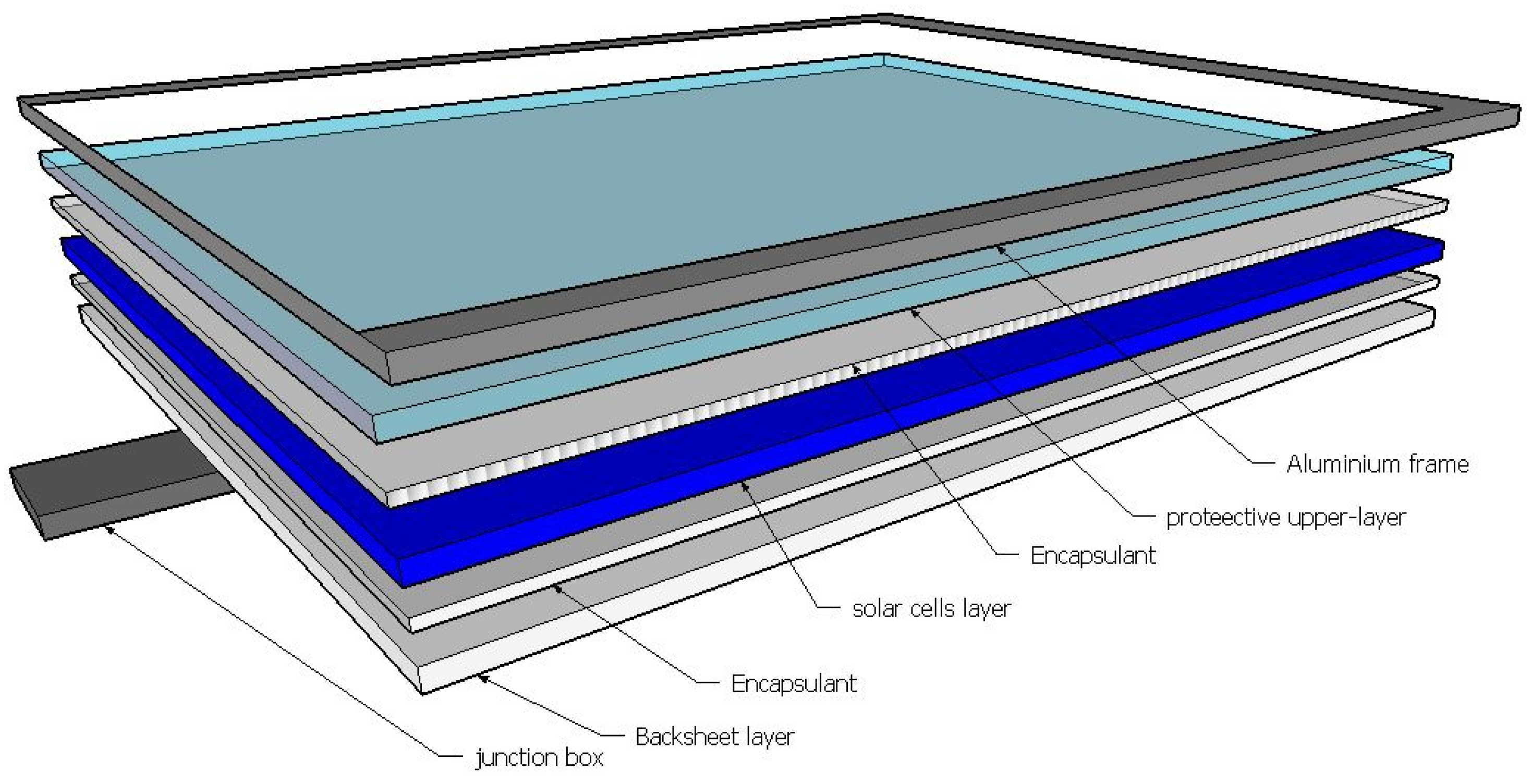
2. Traditional Solar Panels Construction

Encapsulation plays a crucial role in protecting solar cells from external environmental factors and maintaining their structural integrity over the long term. The encapsulation process typically involves the use of a polymer material, such as EVA, which is applied between the front and backboard layers to create a hermetic seal. The EVA layer also serves to reduce the effects of any external mechanical stresses on the solar cell while providing electrical insulation and maintaining the integrity of the solar cell against moisture ingress. Encapsulation is an essential step in the manufacture of silicon solar cells as it helps to prevent the physical damage and electrical failure that can result from prolonged exposure to the elements, and thus ultimately extend the lifetime and performance of the solar cell. A standard panel consists of a frame made of aluminum (Al) alloy, tempered glass, solar cells, EVA, a backsheet, and junction box, as is shown in Figure 1. Following the lamination process, all the components of the solar panel merge into a monolithic structure, making it difficult to make alterations or repair any individual element within the panel.
The incorporation of diverse materials, structures, solar cells, and cell interconnects in the design of present-day solar cell modules has given rise to a multitude of factors that contribute to module failure during initial electrical or environmental testing and field applications. These failures include cracked solar cells, dielectric breakdown, corrosion, fractured metal interconnects, discoloration, and delamination of the EVA encapsulant. The causes of these failures may be mechanical fatigue, long-term exposure to wind, and/or thermally incompatible packaging materials [10].

3. Implementation of the Proposed Repairable Solar Module

This section introduces the novel module structure, which is designed to address common issues affecting traditional solar panel modules, such as the difficulty of replacing damaged solar cells or repairing interconnection failures. The module is made up of three key components: a protective front cover made of glass, solar cells adhered to a printed circuit board substrate, and an openable aluminum frame. The protective front cover is made of glass, which is a common material used in solar panel construction due to its durability, transparency, and ability to protect the solar cells from environmental factors. The solar cells are adhered to a printed circuit board substrate using silver conductive epoxy (model no. 8331D from MG chemical company) in a specific conductive zone. The silver conductive epoxy cures at room temperature, forms strong, permanent electrical connections, provides excellent adhesion to many substrates, and can be stored at room temperature. A stable and secure base is thus provided for the solar cells. The openable aluminum frame is a key feature of the novel module structure as it enables easy access to the solar cells and interconnections within the module. This feature makes it possible to replace any cracked or faulty solar cells, and to repair any interconnection failures. The air gap of 0.7 mm is considered sufficient to create separation between the front cover plate and the solar cells. This gap serves as a thermal barrier, which helps to reduce the temperature of the solar cells and boost their efficiency. The selection of materials and their properties have been carefully considered to ensure the durability and reliability of the module. According to this design, the novel module structure offers a solution to the common issues associated with traditional solar panel modules by enabling the replacement of damaged components and the repair of interconnection failures. This feature extends the lifetime and performance of the solar panel, making it a more sustainable and cost-effective option for generating clean energy. The materials and their properties are listed in Table 1. The primary focus was choosing suitable materials that would meet the technical criteria while also being readily available in the local market.

3.1. Module Preparation

Before fabricating a complete solar module, the following process was repeated to create two modules, one using the traditional encapsulation method and the other using the proposed module structure without lamination. First, sixteen 52 mm × 19 mm mini polycrystalline solar cells (0.5 V/400 mA) were arranged on a 20 × 30 cm2 PCB substrate in a specific pattern and connected in series. Unlike the traditional encapsulation module, no EVA lamination process was used in the construction of the proposed module. In order to fabricate the proposed structure, several procedures were carried out, and these are listed below. Additionally, a visual representation of the processes can be found in Figure 2.
  • Cell sorting: after testing and classifying the cells based on their analogous electrical properties, a copper strip is bonded to the front surface (negative part) of each cell.
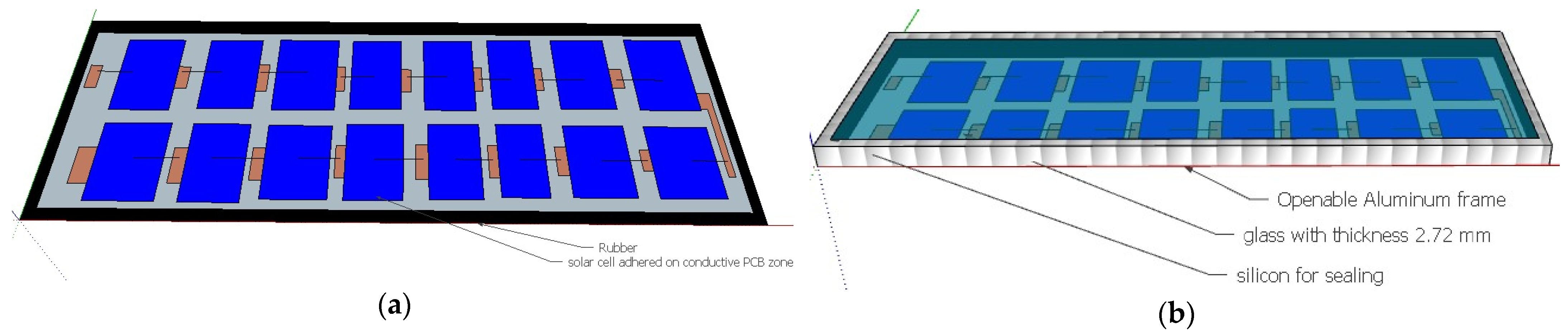
  • Substrate preparation: The preparation of the substrate for the proposed module structure comprises two primary steps. The initial step involves substrate cleaning, which eliminates any impurities or debris that might impact the current flow performance. The second step is to divide the PCB into equal conductive zones; each conductive zone is electrically separated from the other zones and is specified to one solar cell, to which it is adhered using conductive silver epoxy, as is shown in Figure 3a. This step is crucial to guarantee the proper series connection of the solar cells and eliminate any short-circuiting risk.
  • Cell adherence to the substrate: Following substrate preparation, the subsequent step involves firmly adhering the solar cells to the PCB substrate. Both the cell and substrate surfaces undergo thorough cleaning to eliminate any oils or contaminants. Subsequently, 1 gm of silver conductive epoxy is extruded onto the back of each cell. Within a 5 min timeframe, the cells are meticulously positioned over the designated conductive zones on the substrate. The epoxy is then left to cure for one hour, ensuring secure attachment. This process is iterated for each cell in each zone until all the cells are successfully affixed to the substrate.
  • Soldering cell front: the tabbing wire on the opposite side of each cell within a specific zone is soldered to the conductive part of the neighboring zone, effectively connecting the cells in series.
  • Visual examination: the circuit is visually checked to ensure that the circuit has been connected correctly.
  • Assembly: the assembly involves stacking a set of materials consisting of an aluminum frame, rubber sheets, glass, the substrate with the solar cells, and epoxy.
  • Encapsulation: To complete the assembly of the module, the surface edges are cleaned, and the output leads are attached. Strips of rubber are then adhered to the substrate edges using epoxy and left for one hour to cure. Finally, the two plates (glass and printed board) are placed within the openable aluminum frame.
  • Final assembly: the final step is to seal all the edges of the module and the gaps between the glass and aluminum frame with silicon resin to ensure that the panel is protected from humidity, as is depicted in Figure 3b.
  • Final inspection: After the fabrication process, the module is visually inspected to check for any defects or damage that might have occurred during the process. This examination is crucial as it ensures the quality of the module and verifies that it is well sealed and that it will protect the solar panel from short circuits.
  • Repairability check: if any fault occurs in the module, one can easily remove the silicon resin and open the aluminum frame to deal with the fault.

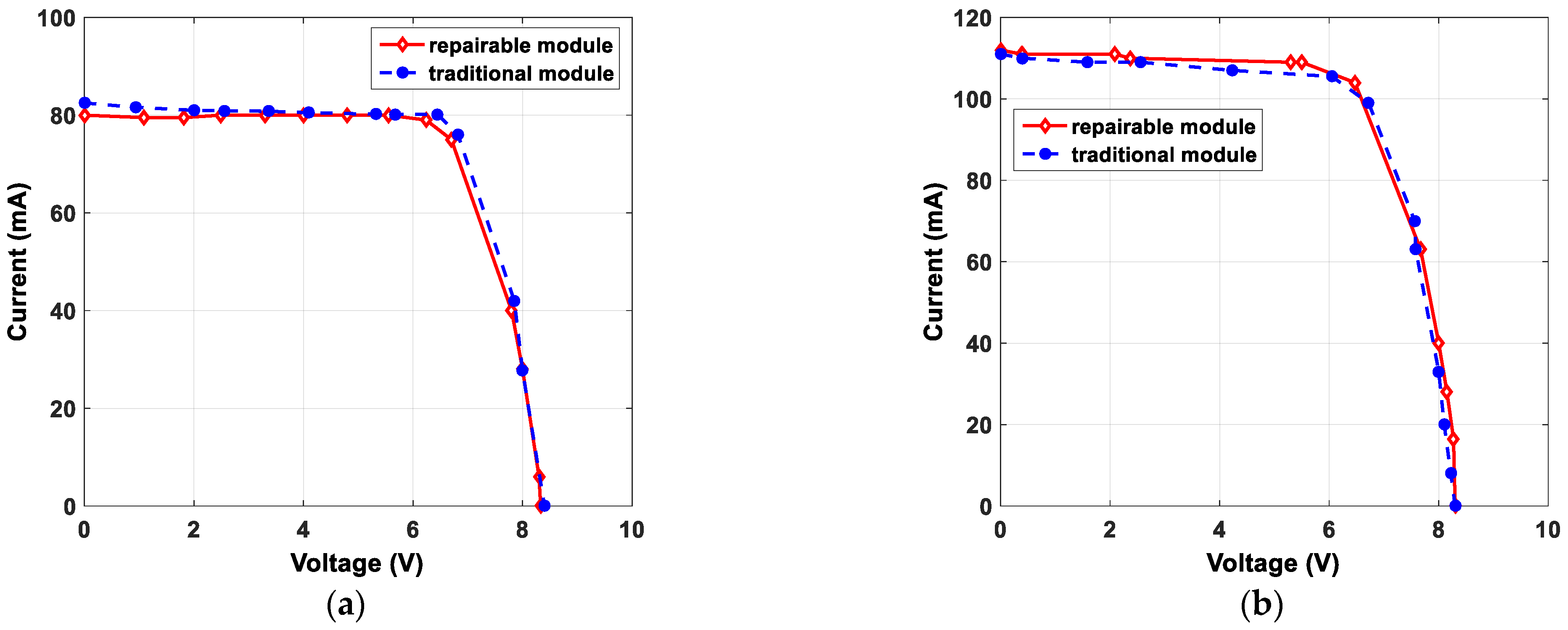
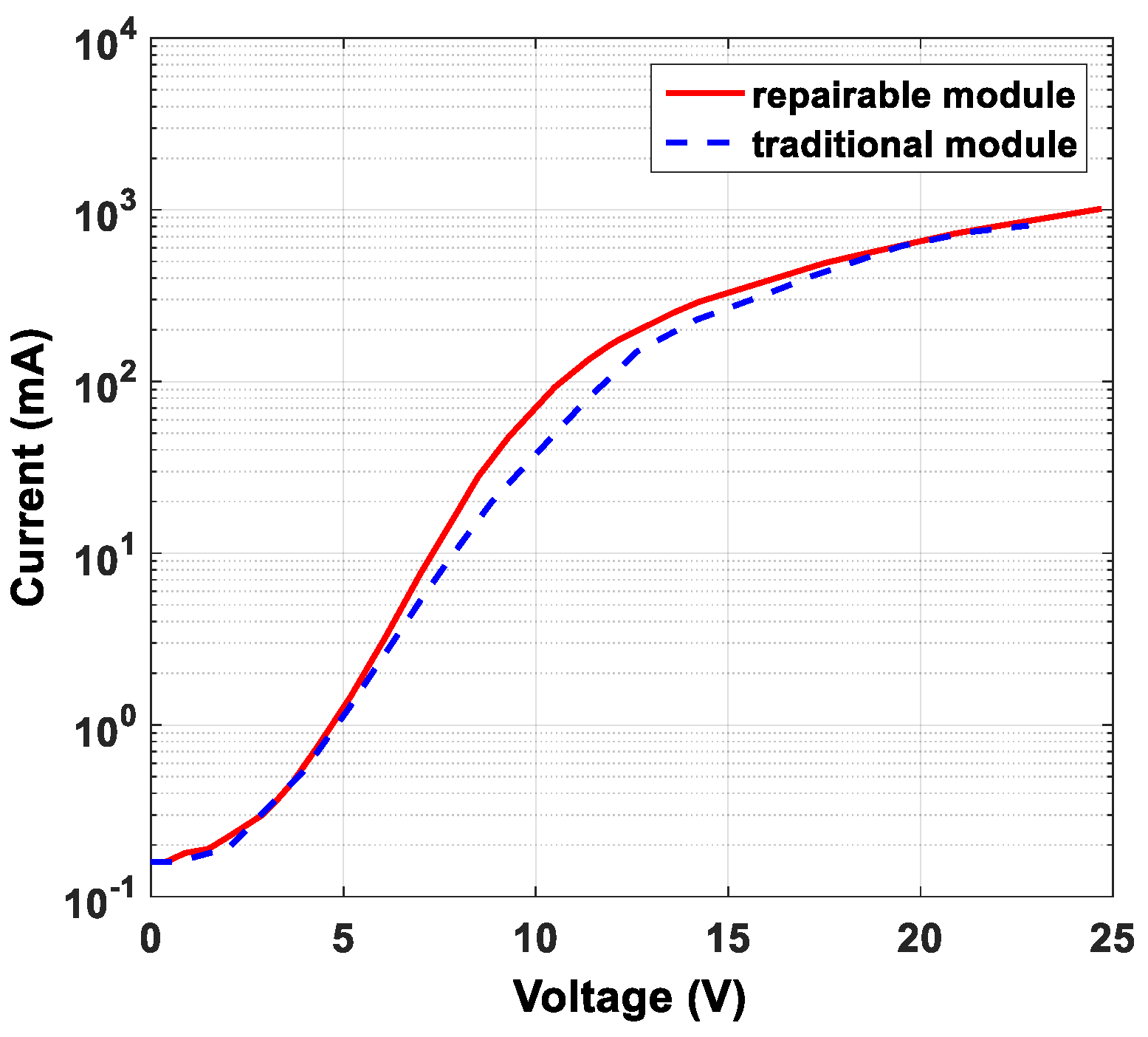
3.2. Electrical Performance Test

During the following tests, both the traditional and proposed modules were utilized. Each module consisted of sixteen mini polycrystalline silicon solar cells. These cells had dimensions of 52 mm × 19 mm and were placed on a PCB substrate measuring 20 cm × 30 cm. Both modules were subjected to the same test conditions to ensure a fair comparison of their performance. The illuminated current-voltage (I-V) measurements were carried out using a specific configuration. The setup included a variable DC power supply, a 1000 W tungsten halogen lamp, and a fixed load. During the measurement process, the variable DC power supply was used to provide the necessary voltage for the solar cells. The 1000 W tungsten halogen lamp, positioned at a specific distance from the modules, served as the light source. The fixed load was connected to the solar cells to measure the resulting current. The results of I-V characteristics under the illumination conditions are presented in Figure 4, where two distinct illuminated powers are specified. In addition, the dark characteristics are illustrated in Figure 5. The figures indicate a striking similarity in the electrical characteristics of both modules under the same illumination conditions. Additionally, when examining the dark curves, slight differences can be observed in the ideality factors (extracted from the slopes of the curves) and the saturation currents (extracted from the intercept of the best fit line). The novel structure exhibited a slightly higher ideality factor and a slightly lower saturation current than the conventional module.

4. Numerical Thermal Analysis

To ensure the maximum power output from a solar cell array, it is important to examine and understand the module’s thermal behavior [11,12] as this maximum power depends strongly on the operating temperature. Thus, the two modules—the proposed module illustrated in Figure 6 and the traditional module that had undergone a lamination process—were evaluated, and their thermal performances were compared.
In the following analysis, the following assumptions were made:
  • Thermal models are established in one dimension (1D).
  • Negligible thermal capacitances are assumed.
  • The PV cell temperature is assumed to be uniform as it has a higher thermal conductivity value than the other layers.
  • The sky temperature Ts is supposed to be equal to the air temperature (Ts = Ta) [13,14].
  • The temperature of the ground (on the back of the PV module) is assumed to be the same as the air temperature (Tg = Ta).
  • The transmission ( τ ), reflection ( ρ ), and absorption ( α ) coefficients for the repairable and traditional modules (independent of temperature) are shown in Table 2.
  • There is almost no internal reflection within the layers of the PV module.
  • The emissivity of the glass remains constant, regardless of temperature and wavelength, and its value is 0.91 [12].
  • The top surface of the PV module is exposed solely to the sky, while the underside is exposed solely to the ground.

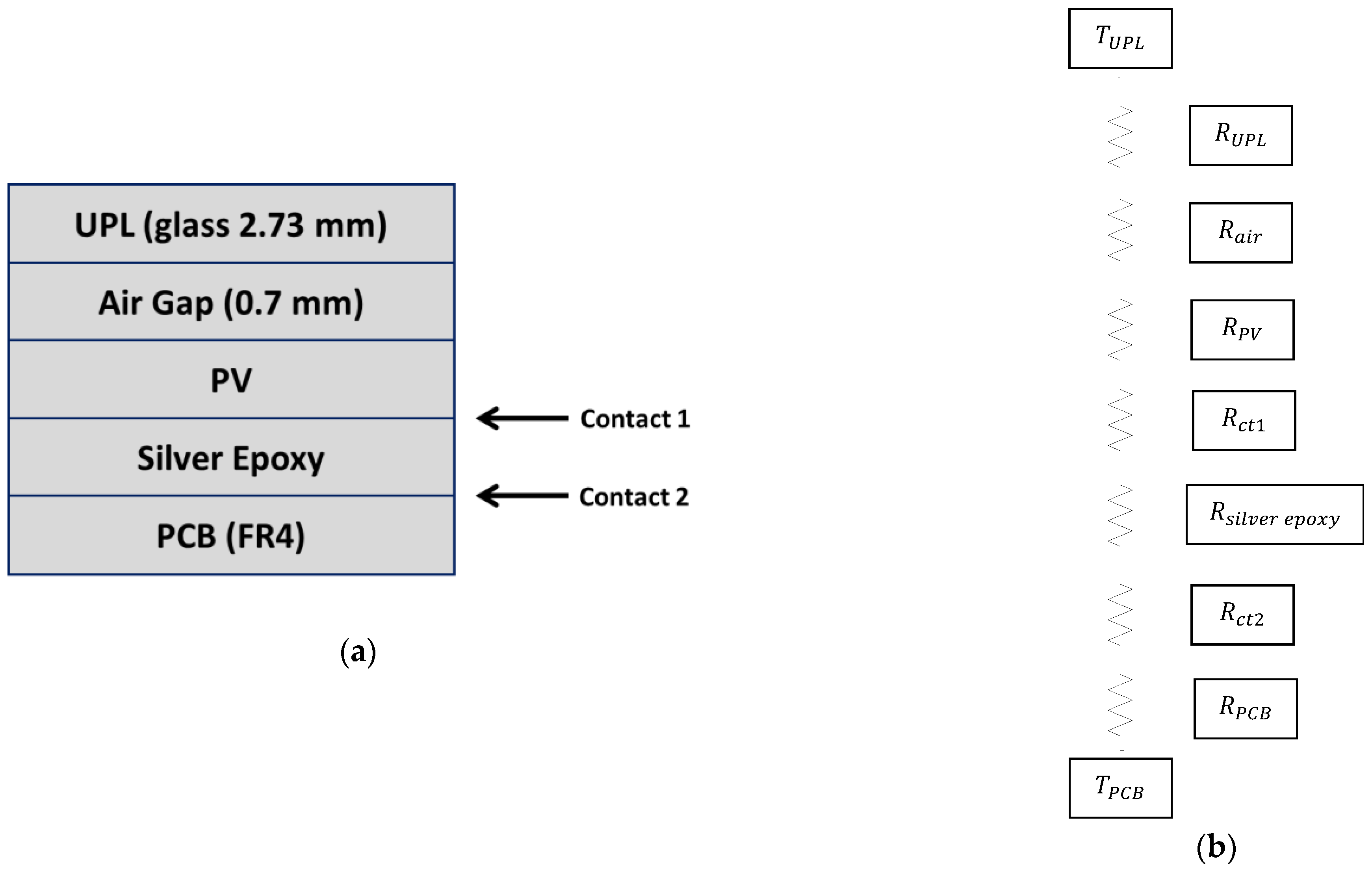
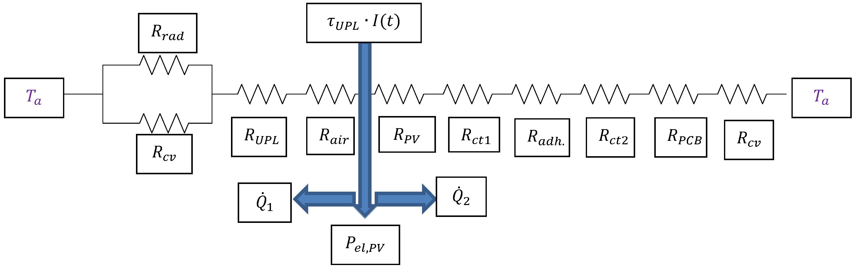
4.1. Repairable PV Module

The schematic presented in Figure 6 shows the structure of the novel module, which consists of two layers with a 0.7 mm air gap between them intended to minimize the thermal stress on the solar cells. Additionally, the module is well-sealed. Further information on the layers and their corresponding thermal resistances can be found in Figure 7 and Figure 8.
The solar PV panel combines multiple PV cells that are coupled electrically in series and thermally in parallel. The packing coefficient of the PV panel ( β p v ) is specified as follows [12]:
β p v = A p v A p a n e l = N c e l l · A c e l l A p a n e l
where A p a n e l is the total surface area of the PV panel that is exposed to incident solar radiation, A p v is the actual area occupied by the PV cells, A c e l l is the surface area of a single cell, and N c e l l is the number of PV cells on the panel.
The equivalent electric network takes into account the transfer of heat through the layers of the PV panel and the energy exchange with the surrounding atmosphere. The upper protective layer (UPL) reflects a portion of the incident solar energy and absorbs another portion, but mainly transmits it to the layers beneath. Equivalent operations appear in the PV layer, which reflects a portion of the incident energy back to the UPL and transmits another small fraction via the PCB back layer to the ambient environment. The absorbed energy is then transferred into electrical energy. In the case of the UPL, the energy balance can be expressed as follows:
E ˙ α , U P L + Q ˙ 1 = Q ˙ C V + Q ˙ r a d
α U P L I ( t ) A p a n e l + T P V T U P L R a i r + R U P L = T U P L T a R C V + T U P L T s k y R r a d
In the case of the PV layer, the energy balance is given by the following equation:
E ˙ τ , U P L = E ˙ α , p v = E ˙ e l , p v + Q ˙ 1 + Q ˙ 2
τ U P L I ( t ) A p a n e l = P e l , p v + T P V T U P L R a i r + R U P L + T P V T a R P V + R c t 1 + R a d h . + R c t 2 + R P C B + R c v
where α U P L is the absorptivity and τ U P L is the transmissivity of the UPL. I t is the incident solar radiation intensity, as shown in Figure 7. Further, the convective resistance at the upper and lower sides is given by the following equation:
R c v = 1 h c v · A p a n e l
Typically, the convective heat transfer coefficient takes into consideration the wind speed (0 < u w < 7 m/s) [15]:
h c v = 2.8 + 3 × u w
The radiation thermal resistance can be formulated as follows:
R r a d = 1 h r a d · A p a n e l
h r a d = ε U P L σ T U P L 2 + T a 2 T U P L + T a
where ε U P L denotes UPL emissivity and σ is the Stefan–Boltzmann constant. For each layer, the thermal resistance is as follows:
R t = L K A
where L is the plane thickness and A is the plane area. The electrical energy generated from the PV module is given by the following equation [16,17]:
E ˙ e l , P V = P ˙ e l , p v = η p v τ U P L I t A P V
P ˙ e l , p v = η p v τ U P L I t β P V · A p a n e l
η p v = η 0 1 β 0 T P V T 0
The subscript “0” represents standard test conditions (STC), which are identified as an incident solar energy of G r e f = I t = 1000 W/m2, a reference temperature ( T r e f ) of 25 °C, and an air mass (AM) of 1.5. From all the above equations, with ignoring the conductive thermal resistance, one obtains the following:
T p v = 0.8024 T U P L + 0.49179 T a + 0.012792 I ( t ) 1.29425 1.466 10 5 I ( t )
0.8024 T U P L + 0.49179 T a + 0.012792 I t 1.29425 1.466 10 5 I t T U P L = 5.9 10 4 I t + 0.70235 T U P L T a + 1.5196 × 10 9 T U P L 4 T a 4

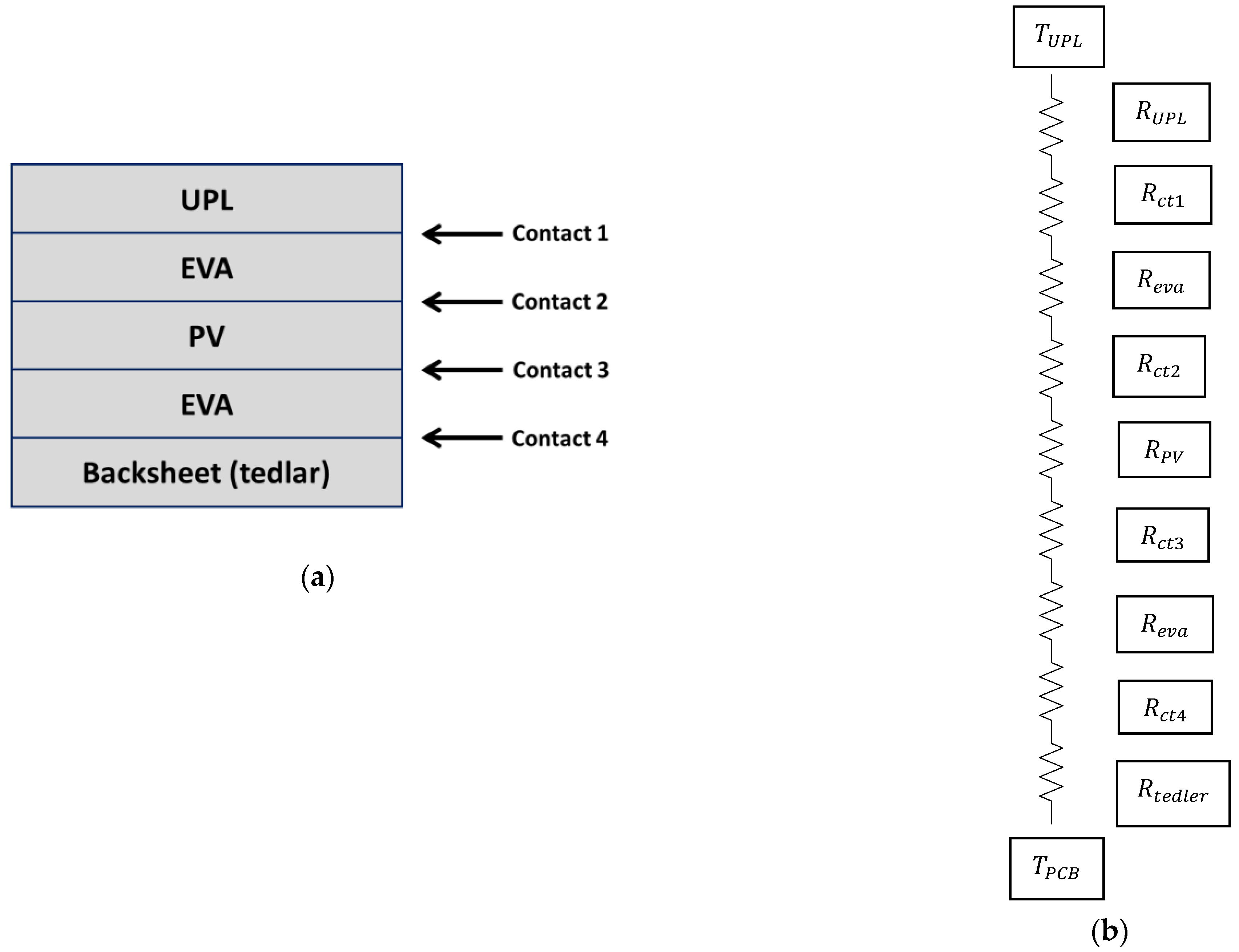
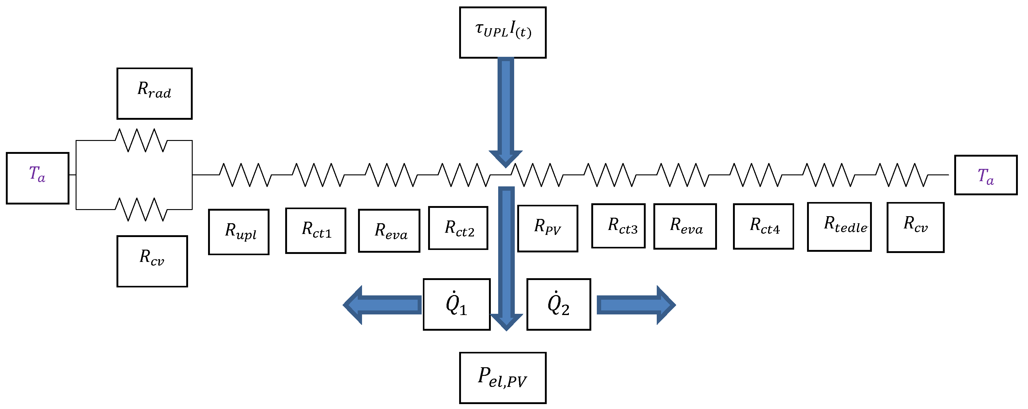
4.2. Traditional PV Module

As has been mentioned above, the typical design of a solar module consists of a front cover, solar cells, a backboard, and EVA, all of which is contained within an aluminum frame. After the lamination process, all the module elements become a monolithic structure. The layers and associated thermal resistances of the traditional module can be represented as in Figure 9 and Figure 10.
In this case, concerning UPL, the energy balance is given as follows:
E ˙ α , U P L + Q ˙ 1 = Q ˙ C V + Q ˙ r a d
α U P L I ( t ) A p a n e l + T P V T U P L R c t 2 + R e v a + R c t 1 + R U P L = T U P L T a R C V + T U P L T s k y R r a d
Regarding the PV layer, the energy balance can be written as follows:
E ˙ τ , U P L = E ˙ α , p v = E ˙ e l , p v + Q ˙ 1 + Q ˙ 2
τ U P L I ( t ) A p a n e l = P e l , p v + T P V T U P L R c t 2 + R e v a + R c t 1 + R U P L + T P V T a R P V + R c t 3 + R e v a + R c t 4 + R t e d l e r + R c v
Using the above equations and the optical parameters from Table 2 for the traditional module, one obtains the following:
T p v = 0.7359 T U P L + 0.04424 T a + 1.0559 10 3 I ( t ) 0.78019 1.21 10 6 I ( t )
0.7359 T U P L + 0.04424 T a + 1.0559 10 3 I ( t ) 0.78019 1.21 10 6 I ( t ) T U P L = 5.3 10 5 I t + 0.06319 T U P L T a + 1.367 10 10 T U P L 4 T a 4

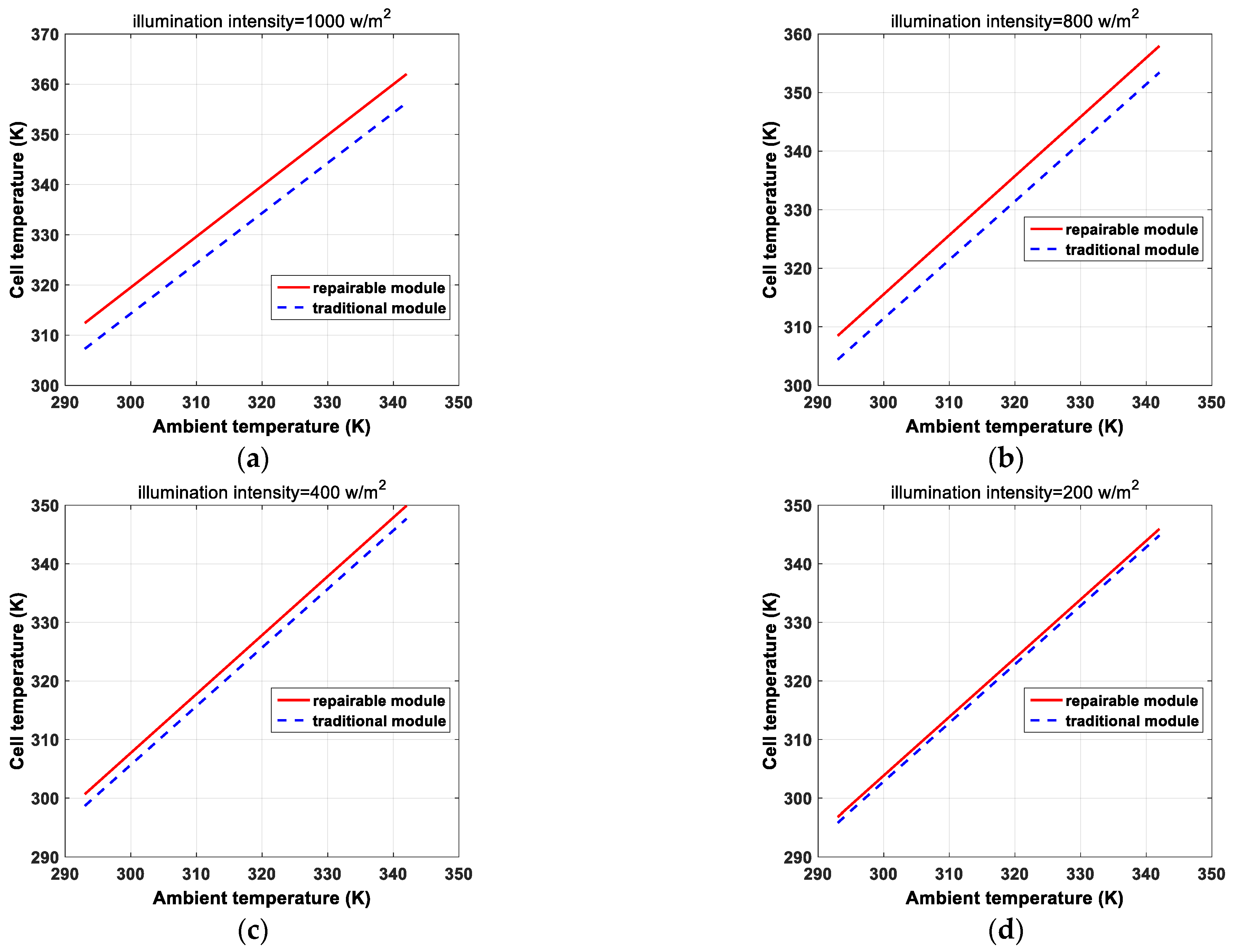
4.3. Numerical Results

Here, the presented numerical models are utilized to evaluate the thermal responses of the two PV panels (the proposed module and the traditional panel) at distinct levels of intensity ranging from 200 to 1000 W/m2. The ambient temperature was varied between 20 to 69 °C, and solar cell efficiency was η 0 = 22 % under standard test conditions (STC). As is shown in Figure 11, a small difference between the cell temperature of the proposed module and that of the conventional module was observed. As the intensity decreased, the difference became less significant. In general, for any intensity level, there will be a small difference in the output power. This may be a defect in the proposed module, which has a slightly lower electrical capability than the traditional module. However, it can be repaired and modified, which will result in consumer confidence in solar panels and help spread the use of solar energy.

5. Conclusions

In this paper, a novel design for a repairable solar panel that incorporates modular components and accessibility to allow for the repair or replacement of defective parts has been introduced. This design enables the retrofitting or upgrading of the installed panels, making it a more sustainable and cost-effective option for generating clean energy. The key feature of this design is its modularity, which enables the easy replacement of faulty or damaged components. The design also incorporates accessibility, which enables easy access to the components within the panel. This feature makes it possible to repair or replace non-defective parts, as well as to retrofit the panel with newer, more efficient components. The experimental electrical analysis showed that both the traditional and the proposed modules have almost the same I–V characteristics. This indicates that the proposed design is as efficient as the traditional solar panel, while also offering the additional benefits of modularity and accessibility. Additionally, from the thermal analysis of the two modules, it was observed that the temperature of the cells ( T P V ) in the proposed module was higher than that in the conventional module, ranging from 1 K to 5.7 K depending on the illumination intensity and ambient temperature. Therefore, the output power of the proposed module is expected to be slightly less than that of the traditional module. The proposed module, in contrast to the traditional module, is designed to be a reliable and repairable solar module, any part of which is accessible.
Overall, the proposed repairable solar panel design offers a solution to the common issues associated with traditional solar panels by enabling the repair or replacement of defective parts, as well as the retrofitting or upgrading of installed panels. This feature extends the lifetime and performance of the solar panel, making it a more sustainable and cost-effective option for generating clean energy. In our future endeavors, we plan to expand our research by conducting extensive experimental work that specifically focuses on outdoor measurements and practical thermal analyses. This will allow us to gather valuable data and insights related to the performance and behavior of the proposed module under real-world outdoor conditions.

Author Contributions

Conceptualization, A.H.Z.; methodology, E.E.-F.; software, E.E.-F.; validation, E.E.-F.; formal analysis, E.E.-F.; investigation, E.E.-F., M.A.A., A.E.-S., A.H.Z., M.A., A.S. (Ahmed Shaker) and A.S. (Ahmed Saeed); resources, E.E.-F., A.H.Z. and M.A.; writing—original draft preparation, E.E.-F., A.S. (Ahmed Shaker) and A.S. (Ahmed Saeed); writing—review and editing, A.S. (Ahmed Shaker) and A.S. (Ahmed Saeed); visualization, A.S. (Ahmed Shaker), A.S. (Ahmed Saeed) and E.E.-F.; supervision, M.A., M.A.A. and A.E.-S.; project administration, A.H.Z. and M.A. All authors have read and agreed to the published version of the manuscript.

Funding

This research received no external funding.

Conflicts of Interest

The authors declare no conflict of interest.

References

  1. Kumar, V.; Pandey, A.S.; Sinha, S.K. Grid integration and power quality issues of wind and solar energy system: A review. In Proceedings of the 2016 International Conference on Emerging Trends in Electrical Electronics & Sustainable Energy Systems (ICETEESES), Sultanpur, India, 11–12 March 2016; pp. 71–80. [Google Scholar]
  2. Irena, I.P. End-of-Life Management: Solar Photovoltaic Panels; National Renewable Energy Lab. (NREL): Golden, CO, USA, 2016. [Google Scholar]
  3. Parida, B.; Iniyan, S.; Goic, R. A review of solar photovoltaic technologies. Renew. Sustain. Energy Rev. 2011, 15, 1625–1636. [Google Scholar] [CrossRef]
  4. Spinelli, P.; Lenzmann, F.; Weeber, A.; Polman, A. Effect of EVA encapsulation on antireflection properties of Mie nanoscatterers for c-Si solar cells. IEEE J. Photovolt. 2015, 5, 559–564. [Google Scholar] [CrossRef]
  5. Xu, Y.; Li, J.; Tan, Q.; Peters, A.L.; Yang, C. Global status of recycling waste solar panels: A review. Waste Manag. 2018, 75, 450–458. [Google Scholar] [CrossRef] [PubMed]
  6. Zekry, A.; Shaker, A.; Salem, M. Solar cells and arrays: Principles, analysis, and design. In Advances in Renewable Energies and Power Technologies; Elsevier: Amsterdam, The Netherlands, 2018; pp. 3–56. [Google Scholar]
  7. El-Shazly, A.A.; Zekry, A.; El-Koosy, M.A.; Farid, M.S. Three flat plates terrestrial (3FPT) module fabrication and testing. Renew. Energy 2001, 23, 509–523. [Google Scholar] [CrossRef]
  8. Tsuno, Y.; Hishikawa, Y.; Kurokawa, K. Translation equations for temperature and irradiance of the IV curves of various PV cells and modules. In Proceedings of the 2006 IEEE 4th World Conference on Photovoltaic Energy Conference, Waikoloa, HI, USA, 7–12 May 2006; Volume 2, pp. 2246–2249. [Google Scholar]
  9. Pantic, L.S.; Pavlović, T.M.; Milosavljević, D.D.; Radonjic, I.S.; Radovic, M.K.; Sazhko, G. The assessment of different models to predict solar module temperature, output power and efficiency for Nis, Serbia. Energy 2016, 109, 38–48. [Google Scholar] [CrossRef]
  10. Chowdhury, M.S.; Rahman, K.S.; Chowdhury, T.; Nuthammachot, N.; Techato, K.; Akhtaruzzaman, M.; Tiong, S.K.; Sopian, K.; Amin, N. An overview of solar photovoltaic panels’ end-of-life material recycling. Energy Strategy Rev. 2020, 27, 100431. [Google Scholar] [CrossRef]
  11. Mirmira, S.R.; Marotta, E.E.; Fletcher, L.S. Thermal contact conductance of adhesives for microelectronic systems. J. Thermophys. Heat Transf. 1997, 11, 141–145. [Google Scholar] [CrossRef]
  12. Hammami, M.; Torretti, S.; Grimaccia, F.; Grandi, G. Thermal and performance analysis of a photovoltaic module with an integrated energy storage system. Appl. Sci. 2017, 7, 1107. [Google Scholar] [CrossRef]
  13. Kalogirou, S.A.; Karellas, S.; Braimakis, K.; Stanciu, C.; Badescu, V. Exergy analysis of solar thermal collectors and processes. Prog. Energy Combust. Sci. 2016, 56, 106–137. [Google Scholar] [CrossRef]
  14. Sarhaddi, F.; Farahat, S.; Ajam, H.; Behzadmehr, A. Exergetic performance evaluation of a solar photovoltaic (PV) array. Aust. J. Basic Appl. Sci. 2010, 4, 502–519. [Google Scholar]
  15. Watmuff, J.H.; Charters, W.W.S.; Proctor, D. Solar and wind induced external coefficients-solar collectors. Coop. Mediterr. Pour L’energie Sol. 1977, 56. [Google Scholar]
  16. Evans, D.L. Simplified method for predicting photovoltaic array output. Sol. Energy 1981, 27, 555–560. [Google Scholar] [CrossRef]
  17. Skoplaki, E.; Palyvos, J.A. On the temperature dependence of photovoltaic module electrical performance: A review of efficiency/power correlations. Sol. Energy 2009, 83, 614–624. [Google Scholar] [CrossRef]
  18. Lupu, A.G.; Hristoforou, E.; Tcaciuc, G.D.; Popescu, A. Theoretical Model for Photovoltaic Panel Thermal Analysis. Bull. Polytech. Inst. Iași. Mach. Constr. Sect. 2022, 68, 79–88. [Google Scholar] [CrossRef]
Figure 1. Traditional solar panel.
Energies 16 06492 g001
Figure 2. Fabrication processes of the proposed repairable solar module.
Energies 16 06492 g002
Figure 3. Schematic representations showing (a) solar cells adhered to a PCB and (b) repairable solar module after sealing.
Energies 16 06492 g003
Figure 4. Results of I-V tests under illumination for both the conventional and proposed modules: (a) first illumination condition; (b) second illumination condition.
Energies 16 06492 g004
Figure 5. Dark I-V characteristics of the traditional and modified modules.
Energies 16 06492 g005
Figure 6. Openable solar module with low iron content and glass cover.
Energies 16 06492 g006
Figure 7. Thermal resistances of the layers of the modified PV structure (not to scale): (a) the proposed panel layers; (b) the thermal resistances associated with each layer.
Energies 16 06492 g007
Figure 8. Thermal resistances and energy fluxes of the proposed PV panel.
Energies 16 06492 g008
Figure 9. Thermal resistances of a PV panel layer configuration [18] (not to scale): (a) typical module layers; (b) thermal resistances associated with each layer.
Energies 16 06492 g009
Figure 10. Thermal resistances and energy fluxes of a traditional PV panel [18].
Energies 16 06492 g010
Figure 11. Cell temperature T p v of traditional and proposed panels versus ambient temperature T a at: (a) I ( t ) = 1000   W / m 2 ; (b) I ( t ) = 800   W / m 2 ; (c) I ( t ) = 400   W / m 2 ; (d) I ( t ) = 200   W / m 2 .
Energies 16 06492 g011
Table 1. Materials used in the proposed module structure.
No.Module PartsCandidate Materials
1Head coverGlass (2.73 mm)
2SubstratePrinted board (FR4)
3Adhesives and sealantSilver conductive epoxy
Epoxy
Tin
Silicon
4Other partsSoldering wires
Aluminum
Rubber
Table 2. Main thermal parameters of the modified and traditional PV module layers.
Layer MaterialS
(mm)
K (W/m.K) ρ τ α
Modified PV
Module
Glass2.731.80.10.880.02
Air0.70.0250.10.880.02
Silicon0.4150--1
Silver epoxy0.21.5---
PCB (FR4)1.50.25---
Traditional PV ModuleGlass2.731.80.10.880.02
EVA0.40.35-0.970.03
Silicon0.4150--1
Backsheet0.30.3--1
Disclaimer/Publisher’s Note: The statements, opinions and data contained in all publications are solely those of the individual author(s) and contributor(s) and not of MDPI and/or the editor(s). MDPI and/or the editor(s) disclaim responsibility for any injury to people or property resulting from any ideas, methods, instructions or products referred to in the content.

