1. Introduction
In a high percentage of new energy-islanded microgrids, the low inertia will lead to more frequent frequency and voltage fluctuations, and the increasing penetration of wind and photovoltaic power systems will make it increasingly difficult to regulate frequency and voltage as the proportion of conventional synchronous generators decreases. Therefore, improving the ability to regulate frequency and voltage under fault conditions is essential to ensure islanded microgrid systems’ safe and stable operation. To solve the problem of poor frequency and voltage regulation during transients due to the lack of inertia in traditional control methods, a virtual synchronous generator (VSG) based control method is proposed to simulate the voltage and frequency regulation characteristics of a traditional synchronous generator by introducing the rotor equations of motion and the frequency and voltage regulation mechanism of a synchronous generator. Increasing the inertia and damping of the system provides voltage and frequency support for the microgrid and improves the stability of the microgrid [
1,
2,
3]. In terms of modeling and characterization of the VSG itself, ref. [
4] investigated the influence of key VSG parameters such as virtual inertia, damping factor, sag coefficient, among others, on the stability of the system; obtained the corresponding mathematical calculation method of the unstable region; and discussed the influence of the key parameters on the instability constraints, but relying on the parameter control and regulation of the VSG itself only makes it more difficult to realize the flexible compensation and absorption of power, and it needs to be combined with the energy storage system to play a more comprehensive role. Reference [
5] considered the effect of the VSG system order on stability and proposed a new fractional-order model predictive controller (FOMPC) to mitigate output power oscillations and achieve optimal frequency and voltage regulation for islanded microgrids, which provides better power compensation and further improves the suppression of frequency and voltage fluctuations compared to the existing MPC-VSG controller performance, but it does not consider issues such as synchronization and transient overcurrent of the VSG itself during faults, which may not play a good role in the transient process. Currently, as the penetration of new energy distributed generation (DG) units in the power system is rapidly increasing, there have been many scholars who have proposed a number of different VSG control methods for microgrids based on inverter control. Reference [
6] introduced the concept of VSG as a way of controlling inverter-based DGs, which supports grid operation during transient periods; it is achieved through the presence of energy storage elements and the use of swing equations to drive the inverter that connects the DG unit to the grid, thus providing external inertia to the grid. Reference [
7] introduced the concept of using virtual synchronous generation as a frequency stabilization method. The effectiveness of the proposed method to stabilize the load frequency was investigated through various test scenarios. Based on the above studies, how to comprehensively utilize the VSG control method in low-inertia islanded microgrids to realize the dynamic and cooperative stabilization control of the microgrid system frequency, voltage, and the VSG itself is the focus of current research.
Currently, as an energy storage system (ESS) can improve additional power support for microgrids and effectively suppress power fluctuations generated by new energy sources, it is often combined with VSG control to achieve a more excellent control effect [
8,
9,
10]. Reference [
11] proposed a coordinated FM control strategy for wind power storage systems based on virtual synchronous machine technology, which gives full play to the short-time power support of wind turbines while reducing the capacity demand of the storage system to achieve stable FM, but there was no specific analysis of the system voltage stability, which makes it easy to become unstable in the case of voltage dips and faults. Reference [
12] proposed a VSG-based voltage fluctuation suppression strategy to achieve stable voltage control at the parallel network through VSG control on the inverter side and reduce the magnitude of voltage fluctuations. However, most of the current VSG controls are only able to control one of the targets for frequency or voltage and are unable to unify the active and reactive power command values for cooperative allocation, so frequency and voltage cannot be optimally controlled at the same time. In addition, when the system frequency or voltage changes are too large or too fast, the traditional VSG control method, although capable of realizing frequency adjustment and inertia support in accordance with a given reference value, cannot dynamically track the frequency change and is not effectively combined and utilized with the energy storage system, so it cannot provide fast reactive power support for the voltage change and therefore does not have the capability of low-voltage ride-through (LVRT).
To address these issues, separate targeted improvements to the VSG’s frequency and voltage control methods during faults are required. For the transient stabilization of frequency, a real-time optimization method similar to conventional optimal control is required to generate a real-time optimal control function to optimize the control effect of the system. Model predictive control (MPC) is able to adjust the control input by predicting the control effect to achieve faster and more stable tracking of the control target [
13,
14,
15]. Due to its advantages of fast response, high accuracy, and better handling of multiple constraints, it has also been widely used in the control of new energy inverters in recent years [
16,
17]. In reference [
18], multiple ESSs in a microgrid were coordinated for charging and discharging control by an MPC method. Reference [
19] proposed to improve transient power sharing among DGs in a microgrid using MPC-VSG control. In reference [
20], an ESS-based model predictive control method was proposed in order to improve the angular stability of off-grid microgrids. By establishing a prediction model for the angular difference, angular frequency difference, and ESS output power and designing a cost function to minimize the angular difference and angular frequency difference as well as the variation of the reference power as a control variable, it is possible to optimize the reference active and reactive power, which is then transmitted to the ESS, improving the angular stability of the SGs and the multivessel VSG system. However, the proportion of the SGs is decreasing year by year in the high-percentage new energy microgrids, and it is necessary to more emphatically consider the cooperation between new energy generation systems and VSGs as a way to realize power stability control. From the above study, it can be seen that the MPC controller can determine the current power reference value based on the prediction of the required output power for the next sampling cycle, and its addition to the active control loop will effectively improve the dynamic stability of the system frequency; for the transient stability control of the voltage, reference [
21] proposed various control strategies such as power smoothing, tracking target control and frequency regulation to allow microgrids with renewable distributed power sources, but does not consider the rational distribution of active and reactive power. However, no improvement was made to the system reactive power support capacity during faults, and the problem of reasonable distribution of active and reactive power was not considered. Reference [
22] reduced the fluctuation of grid-connected network voltage during faults by enhancing the reactive power support of PV grid-connected inverters during grid voltage dips, but for isolated microgrids, the inverter control of reactive power alone could not provide sufficient and fast power support and needs to be improved.
At the same time, the conventional virtual synchronous generator is prone to transient overcurrent and steady-state overcurrent during faults, leading to off-grid or damage to the power electronics, which cannot support its control strategy and may lead to new energy off-grid in severe cases. Thus, reference [
23] added a virtual resistance to the conventional VSG and designed the value of the virtual resistance based on the steady-state current but did not consider the transient inrush current. Reference [
24] tendered the quantitative design of virtual impedance to achieve suppression of overcurrent at low penetration and output of certain reactive currents, but it froze the VSG power loop so that VSG stability, synchronization, and fault dynamic performance were compromised. Reference [
25] proposed an all-pass filter (APF) to precisely lock in the frequency and phase information when a fault occurs in the grid and added damping torque and voltage deviation feedback control to limit the short-circuit current, but it was unable to provide a given reactive current to the grid based on the voltage dip magnitude, among other problems. Reference [
26] proposed a low-voltage ride-through control technique for VSGs that retained the power loop to ensure continuous grid-connected operation of the VSG and provide some reactive support to the grid during short-circuit faults on the basis of limiting the fault current, but it did not take into account the impact of the change in the rotor equation of motion on the synchronization of the VSG during transients, which can easily cause it to go off-grid. It is clear that the VSG control strategy proposed by most scholars is unable to ensure the synchronization and stability of the VSG itself while providing fast and dynamic frequency and voltage stability control of the system and thus needs to be improved.
In summary, this paper proposes a strategy to improve the transient stability of islanded new energy microgrids based on energy storage–virtual synchronizer control, which provides inertia and power support for the microgrid and improves the dynamic stability of frequency and voltage while ensuring the synchronous and stable operation of VSG, in response to the problems of small inertia, low frequency and voltage transient stability, and weak fault ride-through capability of the VSG itself. The main contributions are as follows:
- (1)
In the active control loop of the ESS-VSG, the active power reference value of the VSG is dynamically corrected and updated using the model predictive control method to achieve dynamic frequency tracking control, which can improve the transient stability of the frequency;
- (2)
In the reactive power control loop of the ESS-VSG, dynamic reactive power support can be carried out according to the degree of voltage change by adjusting the size of the reactive power command and introducing PI links in the reactive power loop to speed up the response of reactive power. This can improve the voltage transient stability and ensure that the system has the ability of LVRT;
- (3)
We use VSG-integrated current-limiting technology to suppress inverter transient currents and maintain the synchronization, power angle stability, and dynamic characteristics of the VSG itself so that the control strategy for frequency and voltage can maintain normal operation during transients.
This article is organized as follows.
Section 2 demonstrates the structure of the islanded microgrid system and also discusses some basic concepts of ESS-VSG control.
Section 3 presents the derivation of the proposed MPC-VSG-ESS frequency dynamic stability control method and analyzes the design of the cost function with output constraints and system stability, while the proposed improved reactive power control loop-ESS-VSG control method is presented. In
Section 4, the method for maintaining the stability of the VSG itself during transients is presented. In
Section 5, the effectiveness of the proposed control method is verified by simulated experimental results.
Section 6 concludes the paper and outlines future research directions.
2. New Energy Island Microgrid Architecture and Control Method
At present, due to the small inertia in the high-percentage new energy generation system, it is easy to cause large fluctuations in voltage and frequency during faults. Although the traditional double-loop control strategy of the inverter can achieve transient frequency and voltage control, it requires the use of phase-locked loops to obtain the phase of the microgrid voltage and frequency, and this method requires high transient stability of the microgrid, which is not conducive to operation in weak grids. To solve this problem, this section uses VSG control at the energy storage inverter to enhance the inertia, damping and frequency, and voltage regulation support of the system during grid dips to improve the transient stability of the system.
2.1. System Architecture
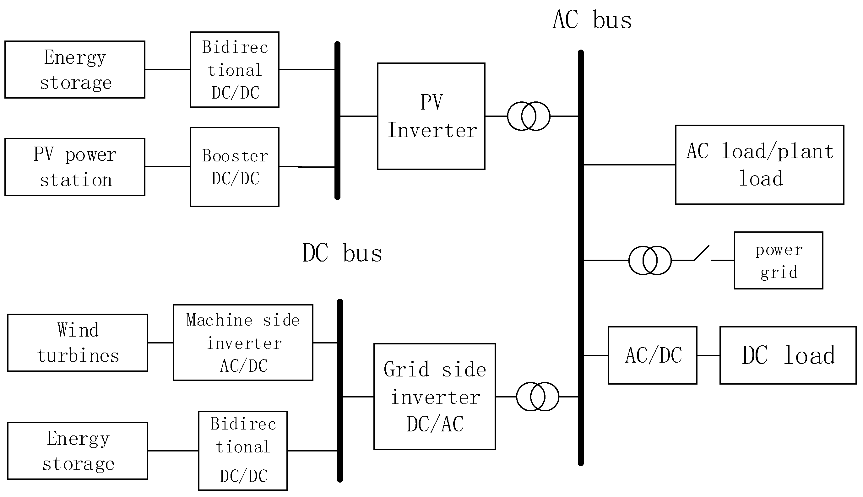
The structure of an islanded microgrid system is shown in
Figure 1. The frequency of the conventional grid is mainly regulated by diesel synchronous generators through inertial forces and automatic voltage regulators. However, the current high proportion new energy microgrid system in the diesel synchronous generator accounts for a relatively low frequency and voltage, mainly relying on the new energy power inverter control and energy storage system for regulation, respectively. Based on the power electronics new energy generation systems that cannot provide sufficient inertia support, the dynamic response of the system frequency and voltage should be further reduced.
The output power of the SG can be obtained as follows [
13]:
where
and
are the active and reactive power output by the SG, respectively;
and
are the voltages at SG and PCC, respectively;
is the line inductance;
is the power angle.
The variation of active and reactive power in SG can be derived by converting Equation (1) into a small signal model:
where
is the power angle at steady state;
is the voltage at PCC at steady state; The change in power angle
is an indirect representation of the system frequency
;
relates to the changes in active power,
, and the changes in voltage,
.
Frequency and voltage fluctuations can also be exacerbated by load changes in the microgrid. As the load increases or decreases, the output power of the generation unit cannot change abruptly. Changes in supply and demand based on both sides will take time to reach a new power balance point, and the quality of the output power will deteriorate during the transition process, making it even more impossible to regulate frequency and voltage effectively during transients, which could lead to new energy sources going off-grid or to widespread blackouts in severe cases.
2.2. ESS-VSG Control Method
Today, an ESS is installed to increase the inertia of the microgrid. By detecting the frequency at the PCC, the ESS can provide the required active and reactive power support in the event of a frequency drop. In addition, if the PCC frequency rises, the ESS absorbs additional power to maintain the system’s power balance, which mitigates frequency–voltage fluctuations.
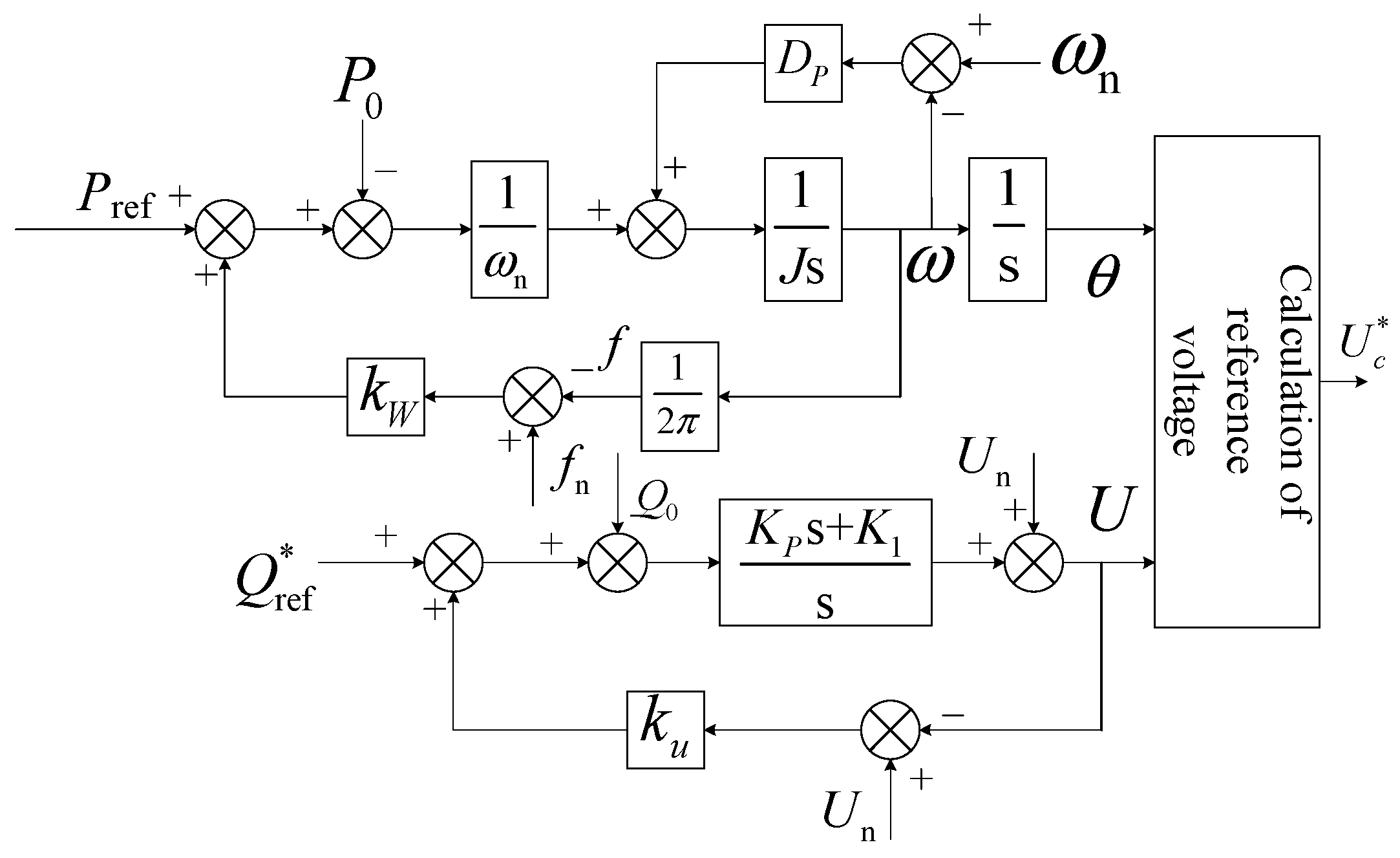
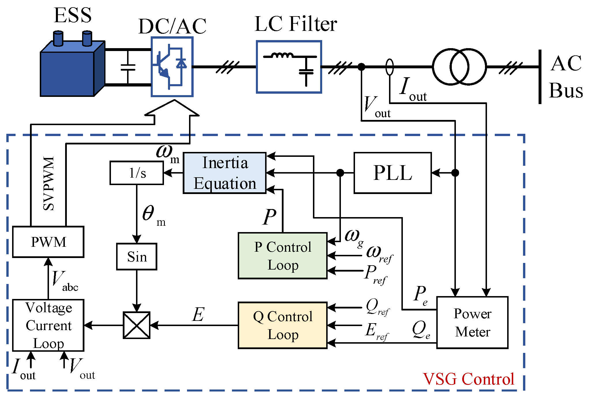
ESS-VSG control provides power support through the energy storage system and achieves inertia support through VSG control. The control method is shown in
Figure 2, where the P and Q control loops are sagged [
13]. The active control loop P is used to achieve primary frequency control, and the inertia equations in the VSG are used as secondary frequency control. As reactive power mainly affects the voltage at the PCC, the reactive control loop Q is used for output voltage control.
The mathematical model of the
P and
Q control loops can be expressed as given [
27]:
where
and
are the sag coefficients for frequency and reactive power, respectively;
and
are reference values for active and reactive power, respectively;
and
are reference values for the voltage at the PCC terminal and the angular velocity of the VSG, respectively;
and
are the measured frequency and reactive power, respectively.
The equation of inertia in VSG is shown below:
where
and
are the rotational inertia and damping coefficient, respectively;
and
are the mechanical and electromagnetic powers, respectively;
and
are the mechanical and rated angular frequencies, respectively.
The power balance of the system can be ensured through frequency and voltage sag control, but the power changes cannot be tracked and adjusted in real time by simulating only the rotor equations of motion in Equation (4), and in the case of substantial load changes or faults, the frequency and voltage fluctuations may be very large and may even push the microgrid into an unstable state. Therefore, the active and reactive power control loops in the conventional energy storage VSG control strategy need to be improved.
3. Dynamic Frequency and Voltage Stabilization Control on ESS-VSG
The power command values in the conventional ESS-VSG control method do not track frequency and voltage changes; this does not allow for good dynamic regulation during power fluctuations and cannot be adjusted to changes in system frequency and voltage, respectively [
28]. Therefore, improvements are made to the active and reactive control loops in this section, respectively.
3.1. MPC-ESS-VSG Control Method
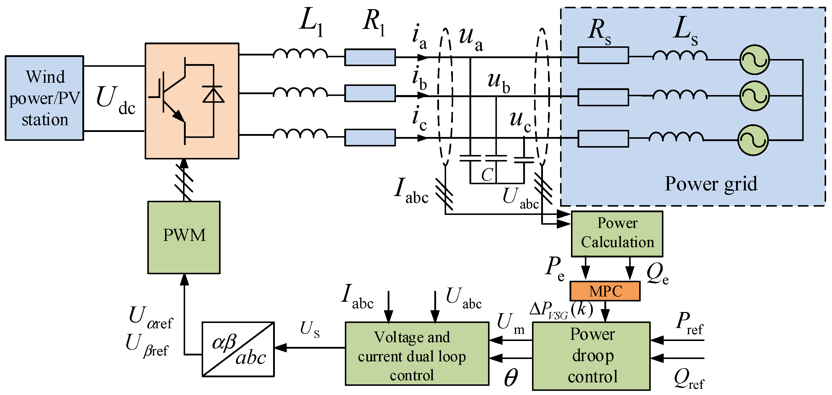
In order to achieve more effective dynamic regulation of transient frequencies, this section proposes a MPC control strategy for energy storage VSG. As shown in
Figure 3, dynamic power tracking is achieved by detecting changes in frequency, and predictive control of active power output changes based on the system model, which enhances the frequency transient regulation capability of the VSG.
3.1.1. Building Predictive Model
Model predictive control first requires a mathematical model of the system under study. According to Equation (4), the inertia equation of the VSG can be rewritten as a state space equation, as shown in the following equation:
where
;
is the controlled input variable to the VSG; output power
can be considered as a measurable disturbance.
After transforming Equation (5) into a discrete incremental model, the discrete equation of state is as follows:
where
where
is the sampling time.
The change in frequency, mechanical power, and electromagnetic power can be expressed:
To improve the prediction accuracy and ensure accurate tracking of power, a three-step prediction is chosen as the prediction range. The frequency prediction equation can be expressed as given [
14]:
where
where:
,
, and
are the matrices formed by Equation (15) under the sampling time;
is the state prediction matrix;
is the prediction error covariance matrix;
is the control error agreement difference matrix;
I is the unit matrix [
13].
3.1.2. Design of Cost Function
The cost function takes into account the frequency deviation
and the variation of the rated power of the VSG
so that the weighted sum of squares is minimized, as shown in the following equation:
where
and
are the weighting factors for frequency and power changes, respectively;
and
are the angular velocity error and the active power error at moment
k, respectively.
Fluctuations in frequency should be limited so that the MPC optimization problem with constraints can be described as follows:
The cost function in Equation (12) should satisfy the following frequency constraint:
The matrix form of Equation (12) is as given below:
where
and
are the weighting factor matrices for the angular frequency and active power errors, respectively;
is the control output reference sequence at
k + 1.
Usually, the analytical solution to the optimization problem in Equation (12) cannot be obtained due to the presence of constraints. However, when using the numerical solution approach, the MPC optimization problem with constraints is also a quadratic programming problem, and therefore, the optimization problem can be transformed into a quadratic programming (QP) problem. At this point, Equation (14) can be converted to , where is the independent variable of the optimization problem.
Next, we bring Equation (9) into Equation (14) and define the following:
Then, the cost function in Equation (14) transforms:
where
The constraint in Equation (13) is then converted to the form of
:
Combining this with Equation (9), the final frequency constraint can be expressed:
Based on the above process, the MPC optimization considering the frequency constraint is transformed into a QP problem and can be expressed:
where
Since in Equation (17) , the QP problem has an explicit analytical solution for any weighted matrix: .
According to the working principle of model predictive control, an initial control sequence will be applied to the system. At the next sampling cycle, the constrained optimization problem is updated, and the solution in Equation (21) is re-solved. After obtaining the optimal solution
, the first of these sequences
is re-entered into the system as a control variable to obtain the change in the VSG active power reference as given:
Finally, the power reference value of the VSG can be continuously corrected by calculating the change in the optimal active power reference value, enabling frequency to achieve a better dynamic response.
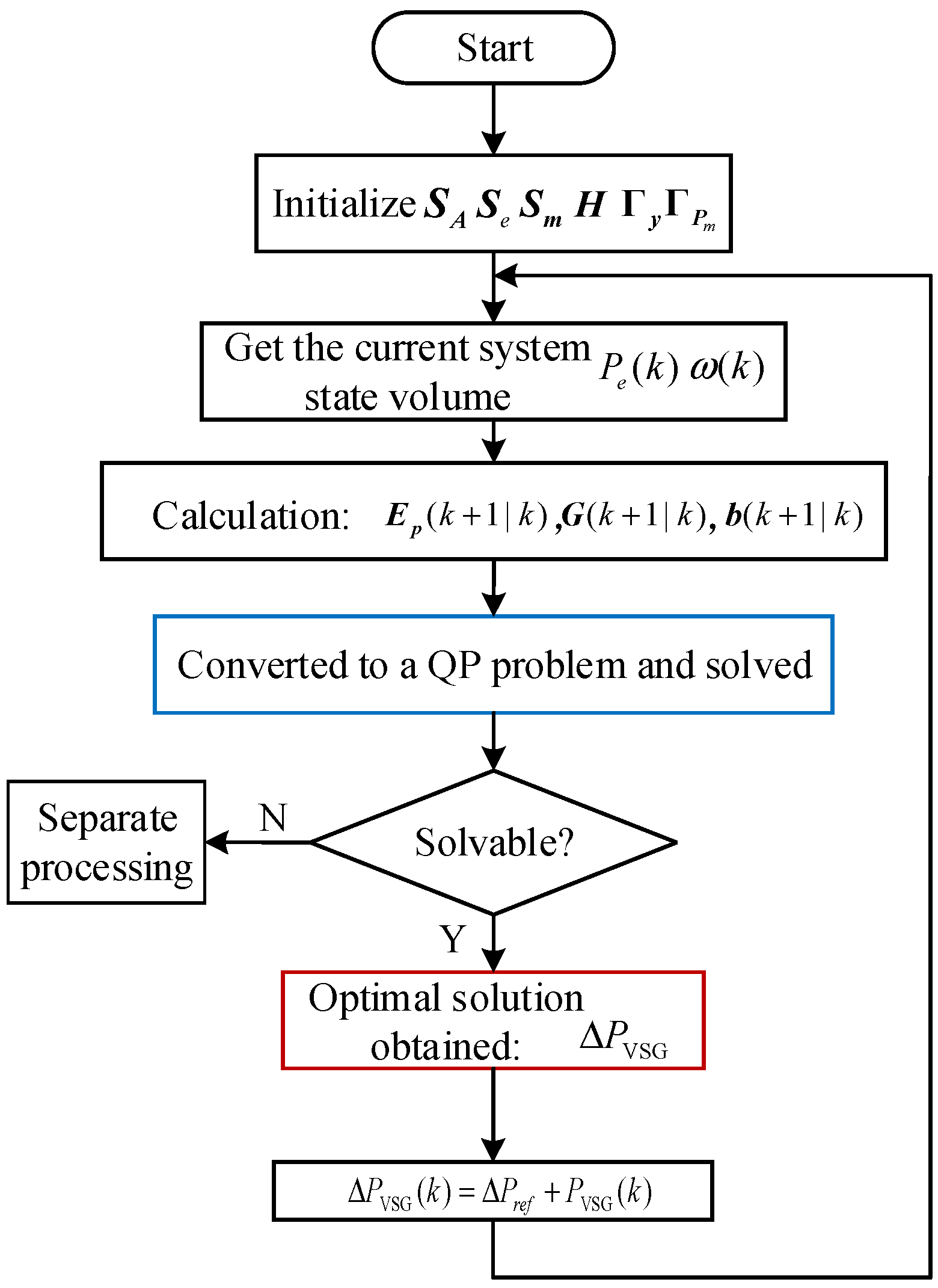
The MPC-ESS-VSG control flow is shown in
Figure 4. The proposed method can calculate the incremental power demand based on the current state by solving an optimized cost function with frequency variation range constraints, and this reduces the frequency shift during transients. Once a disturbance has occurred in the microgrid, the method allows the output power reference of the VSG to be changed taking into account the rate of change of frequency and minimization of frequency errors, which is superior to conventional VSG control methods.
3.2. Improved Reactive Power Control Loop–ESS-VSG Control Method
This section proposes an improved reactive power control loop–ESS-VSG control method so that the ESS-VSG control has the ability to dynamically support reactive power and is able to inject reactive currents of the appropriate size within a defined period of time; it has low voltage ride-through capability to ensure the transient and stable operation of new energy microgrid system.
Take wind turbines as an example: China’s latest national standard GB/T 19963.1-2021 “Wind farm access to the power system technical regulations” applies when a three-phase short-circuit fault occurs in the power grid; then, the wind farm should have dynamic reactive power support when the voltage at the grid point is lower than 80% of the nominal voltage. When the voltage at the grid is less than 80% of the nominal voltage, the wind farm should have dynamic reactive power support capability power. And the dynamic reactive current increment of the wind farm should respond to the voltage change of the grid connection point. The dynamic reactive current increment of the wind farm should respond to the voltage change of the grid point and satisfy the Formula (24):
We now specify that the dynamic reactive current proportionality factor Kt should take a range of values not less than 1.5 and preferably not greater than 3; in this paper, we set Kt to 2.
Next, we transform the above equation:
where
igq is the required output reactive current size in the event of a voltage dip/rise;
igq (
t−) is the magnitude of the output reactive current before the voltage dip/rise.
It follows that the reactive power command should be regulated in proportion to the corresponding voltage dips/rises, as shown in Equation (26):
where
is the output reactive power command value required during transient time;
ufd is the d-axis component of the fault point voltage.
As can be seen from Equation (26), by adjusting the size of the reactive power command so that it rises/dips, it can indirectly inject/absorb reactive currents to meet the requirements for injecting reactive currents when the voltage dips/rises. However, as the conventional virtual synchronous generator reactive power loop only contains an integration link, the power loop response is slow and cannot output a specified size of reactive current in a short period of time. Therefore, this section introduces PI links in the reactive power loop to speed up the response of reactive power. The improved reactive power control loop is shown in
Figure 5.
Herein, J is the virtual rotational inertia; is the frequency modulation factor; is the frequency sag factor; is the output voltage rating; is the pressure regulation factor; and are the reactive power loop scaling and integration factors, respectively; is the reference value for the voltage at the VSG output machine; and are the actual output instantaneous active power and reactive power averages; Pref is the active power command value at fault.
The size of
Pref can be determined by determining the size of the active current
, and the active current is calculated from the magnitude of the reactive current; the formula is shown as follows:
At the same time, when the grid voltage is unbalanced, fluctuations in the instantaneous active and reactive power are reflected in the reference voltage amplitude and phase angle through the active and reactive control loops, resulting in a three-phase imbalance in the output current. In this case, the active power command value of the VSG needs to be reset in order to enhance the transient power angle stability of the VSG and to avoid potential distortion in the VSG during a three-phase unbalanced fault. The average instantaneous power is substituted into the power control loop to obtain a constant reference voltage amplitude U, a phase angle θ, and a reference value for the positive sequence voltage ; the positive sequence output current control is achieved by feeding it into the positive sequence voltage and current control loop. To achieve a balanced three-phase output current, the negative sequence current command value is set to 0, and the negative sequence current can be suppressed by feeding it into the negative sequence current control loop to achieve a three-phase balanced output current.
In the control loop of the VSG, the reactive power command value is reset to provide support for the grid voltage, and the active power command value is reset for current division control to achieve three-phase balancing of the output current, enhancing the ability of VSG to support the grid voltage and fault ride-through capability and achieving dynamic stability control of the transient voltage.
4. VSG Self-Stability Control Method
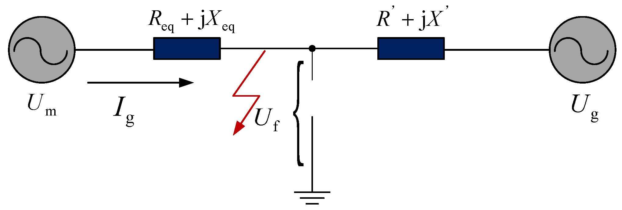
When a short-circuit fault occurs in the microgrid, the equivalent model of the virtual synchronous generator is as shown in
Figure 6.
The fault point voltage is related to the network characteristics, equipment characteristics, and the extent of the fault and can be expressed as below:
where
Uf(0
−) and
Uf(0
+) are the voltage at the fault point before and during the fault, respectively; Δ
Uf is the amount of voltage change at the fault point (both magnitude and phase change).
In the event of a microgrid fault, the amplitude and phase of the internal potential
Um of the VSG can be approximately assumed to be essentially constant:
When a short-circuit fault occurs in the microgrid, the voltage and current dynamics of the virtual synchronizer satisfy the basic circuit equation:
where
Ig is the virtual synchronous generator output current;
Uf is the fault point voltage.
The voltage and current loop in the virtual synchronous generator is equipped with a quasi-PR controller, and the steady-state current is able to track the reference value quickly. As the virtual synchronous control strategy power loop simulates the rotational inertia of the synchronous generator, and the reactive power control loop is an integral link with a slow response, the virtual internal potential
Um changes in accordance with the original power command random electrical time constants, and the process of change is relatively slow. The output current command value, therefore, has a long transition process. Therefore, the decay characteristics of the instantaneous fault current can be neglected, and the fault current of the VSG can be expressed as given:
As can be seen from Equation (31), the fault current is proportional to the amount of change in the voltage vector at the fault point and inversely proportional to the equivalent impedance from the VSG to the fault point. Normally, the equivalent impedance from the virtual synchronous generator potential to the fault point is small, less than 0.1 pu. When a symmetrical fault occurs in the grid (voltage drop of 0.5 pu), the fault current will reach five times the rated current size if no fault current-limiting measures are taken.
A grid-configured converter with a VSG at its core can be equated to a voltage source. In the event of an unbalanced drop in grid voltage, the VSG as a generator model loses synchronization; the VSG is unable to adjust the output voltage within a short period of time due to inertia, resulting in an instantaneous increase in output current. As power electronics are less resistant to overvoltage and overcurrent than conventional synchronous generators, failure to take any current-limiting measures may cause the virtual synchronous generator to trip and damage the power module. This shows that the traditional virtual synchronous control strategy is unable to maintain normal operation during transients, which affects the implementation of the control strategy and needs to be improved.
4.1. Fault Current Suppression
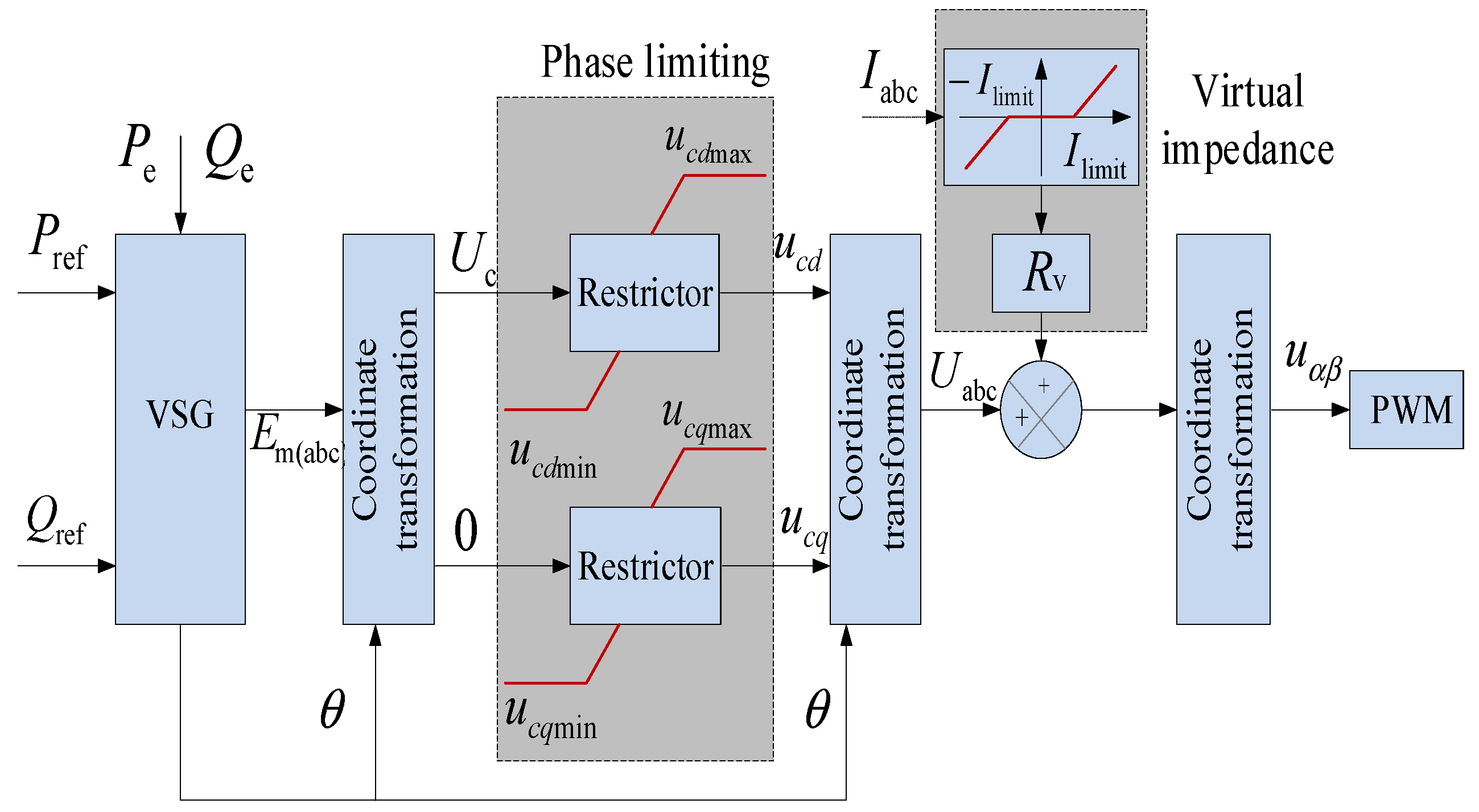
From Equation (30), it is known that increasing the equivalent impedance from the VSG to the fault point or reducing the fault point voltage vector difference can limit the fault current at the VSG. Combining the above two current-limiting measures, this section proposes a comprehensive current-limiting method using a combination of virtual impedance and phase volume limiting.
The virtual impedance corresponds to an increase in the equivalent impedance from the VSG to the fault point, which will provide a phase limit and virtual impedance for limiting the transient inrush current of the VSG; phase current limiting corresponds to reducing the voltage difference between the potential in the VSG and the fault point, limiting the steady-state fault current in the VSG. The VSG-integrated fault current-limiting method is shown in
Figure 7.
Virtual impedance can increase the equivalent output impedance of a virtual synchronous generator, changing the output impedance characteristics. Taking into account the virtual impedance, during a fault in the grid, ignoring the transient component decay characteristics of the VSG, the fault current of the VSG can be expressed as follows:
where
Rv + j
Xv is the additional virtual impedance.
Assuming a three-phase short-circuit fault at the end of the VSG, the equivalent impedance of the potential within the VSG to the point of fault can be approximated as the filtering impedance of the VSG, which is relatively small, usually less than 0.1 pu. The fault current expression for VSG changes from Equation (32) to Equation (33).
The instantaneous value of the fault current can be expressed as given:
Considering the most severe fault in the microgrid (voltage dip of 0 at PCC), the virtual synchronous generator output transient current should always be within the tolerance range of less than 1.3 pu; then, the change in the fault current due to grid fault should be less than 0.3 pu, and the corresponding virtual impedance mode should be greater than 3 pu. The voltage drop across the virtual impedance for the normal VSG operating current will affect the dynamic performance of VSG. In order not to affect the dynamic characteristics of the VSG during normal operation of the grid, this paper uses segmented virtual impedance, and during normal operation of the VSG, no virtual impedance is put in, and when the fault current exceeds a set threshold, the virtual impedance is put in to suppress the overcurrent, and the overcurrent threshold is set to 1.35 pu.
Phase current limiting is mainly used to limit the fault current by limiting the voltage vector difference between the virtual internal potential of the VSG and the fault point, thus minimizing the current oscillations caused by frequent virtual impedance throwing during grid faults. In practice, the voltage difference between the potential within the VSG and the fault point cannot be directly measured to limit this voltage difference directly. In this section, a rotating coordinate system is selected as the reference coordinate system, and the VSG virtual internal potential and output current are projected simultaneously under the VSG rotating coordinate system. The voltage difference between the internal potential and the converter terminal voltage (Ut) is limited according to the maximum (continuous) current vector (Imax), which indirectly limits the voltage difference between the internal potential and the fault point.
The projection of the VSG output current into the rotating reference coordinate system must satisfy the constraints as shown in Equation (35):
where
Idmax and I
qmax are the maximum continuous operating currents in the dq0 axis in the rotating coordinate system, respectively.
The potential
Um within VSG satisfies the constraint in Equation (36):
As the output current has been limited in this section, no overcurrent will occur due to active current. Therefore, the upper section can maintain a certain degree of active power output in the case of a large reactive current igq setting in order to prevent large fluctuations in frequency due to the absence of active power and to ensure maximum injection of reactive current while achieving stable regulation of frequency.
4.2. Stable Control of the Rotor Equation of Motion for VSG
The equation of motion of the VSG rotor is shown in Equation (4). Conventional VSG implement these equations by introducing two integral links in the control loop, but introducing two integral links in a single loop control can cause the control system to oscillate when the grid voltage dips. This section considers the introduction of a damping torque to stabilize rotor motion, slow down rotor angle changes, and maintain synchronization in the event of a VSG fault.
Assuming that the losses of the VSG are negligible, and the input power of the prime mover is equal to the output power of the VSG, the torque of the VSG
Te at this point is as follows:
where
is the output voltage; Equation (37) shows that the torque will fluctuate significantly as the grid voltage drops. For this reason, the quasi-differential link of the VSG torque is introduced as a damping torque to keep the rotor’s motion process stable.
As differential control responds very strongly to abrupt signals, when using a differential link in the feedback channel, the reference input is not involved in the differential process so that a smoother controller output is obtained when the reference input changes abruptly. The transfer function of the differential link can be expressed:
The damping torque provided by the damping winding is shown in Equation (39):
where
is the gain of the quasi-derivative link;
is the time constant of the quasi-derivative link.
With the introduction of this link, the damping winding will suppress the periodic oscillations of the active power when the active power is given a sudden change and cause it to disappear after several oscillation cycles, quickly reaching the new active power given value.
5. Example Simulation
To verify the effectiveness of the control strategy proposed in this paper, a simulation model of the system structure shown in
Figure 1 was built based on MATLAB/SIMULINK. The parameters of the system are shown in
Table 1.
5.1. Frequency and Voltage Transient Stability Verification
In order to verify the effectiveness of this paper’s strategy in controlling the frequency and voltage dynamics of the microgrid system when the load changes, a short-circuit fault was set on the load side at t = 8 s and recovered at t = 16 s.
In order to highlight the superiority of the frequency control strategy in this paper, conventional sag control and conventional energy storage VSG control [
29] were compared with the control in this paper, respectively, and the frequency stabilization control effect is shown in
Figure 8,
Figure 9 and
Figure 10.
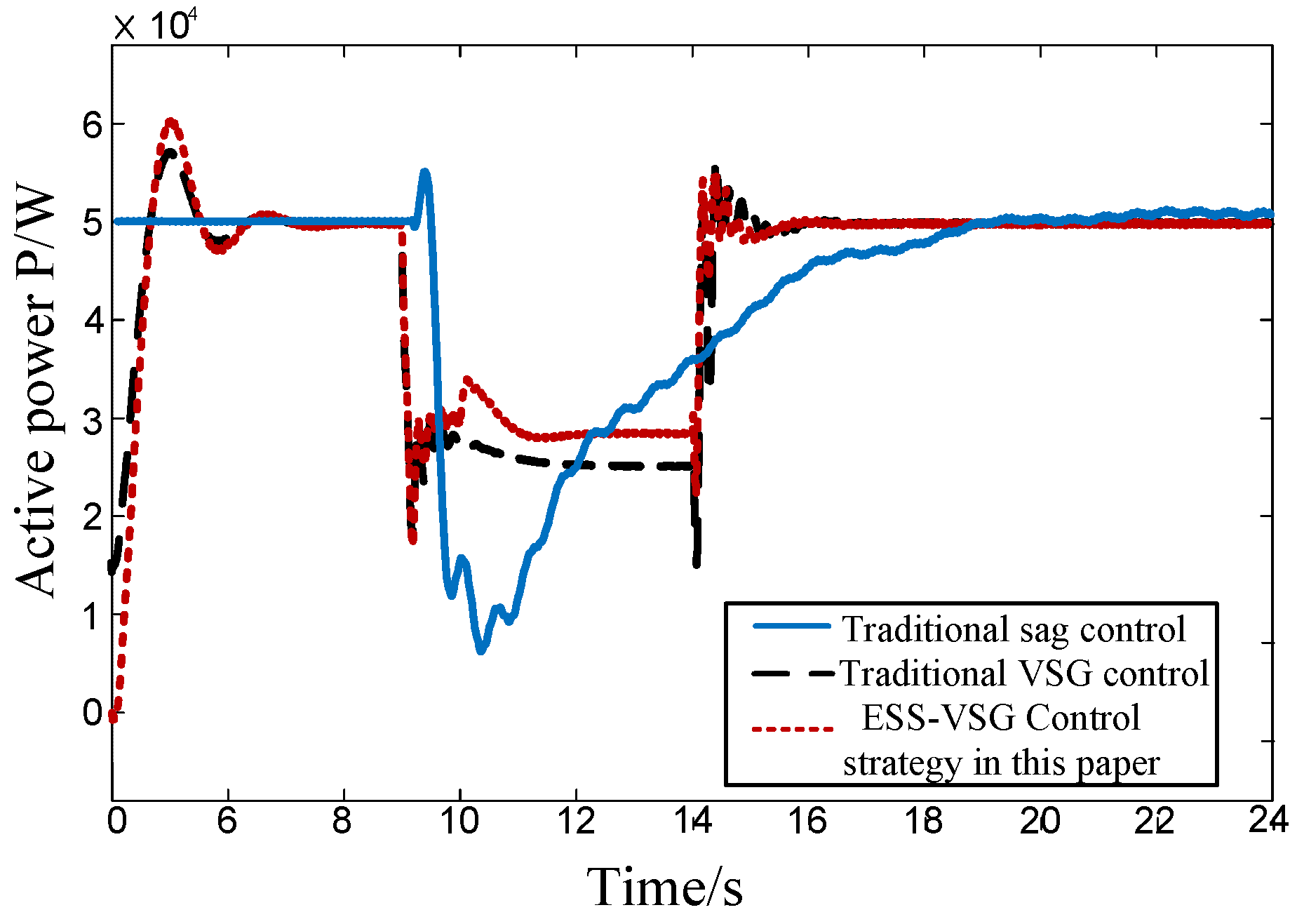
Figure 8,
Figure 9 and
Figure 10 show the VSG output active power variation, the system frequency, and the rate of frequency change during transients.
As can be seen from
Figure 8, the active power output from the conventional VSG and sag control cannot reach the commanded value, the power angle gradually diverges, and the active power drops by a large amount, up to 45 kW, which can affect the system frequency. Compared to the other two control methods, the MPC-VSG control maintains the active power’s dip within 20 kW by resetting the power reference value of the VSG.
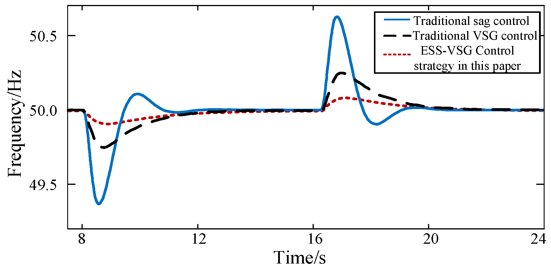
As can be seen from
Figure 9, with conventional sag control, conventional storage VSG control, and MPC-VSG control, the frequency fluctuations at the PCC are approximately 0.67, 0.24, and 0.18 Hz, respectively. The frequency variation is reduced by approximately 72% and 25%, which significantly improves the power quality and enhances the frequency stability of the system.
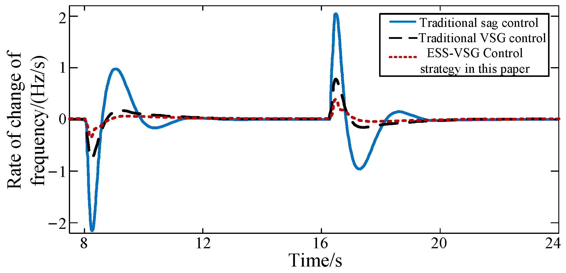
As the frequency changes, the rate of change of frequency is also of interest, as shown in
Figure 10. Under conventional sag control, the maximum frequency change rate is approximately 2.26 Hz/s, and the maximum frequency change rate of the conventional VSG method is approximately 0.75 Hz/s, neither of which meets the criterion of a frequency change rate ≤ 0.6 Hz/s. The maximum frequency variation rate of the proposed method is about 0.55 Hz/s, which is about 75% and 26% lower than the other methods, respectively, and meets the requirements of the standard.
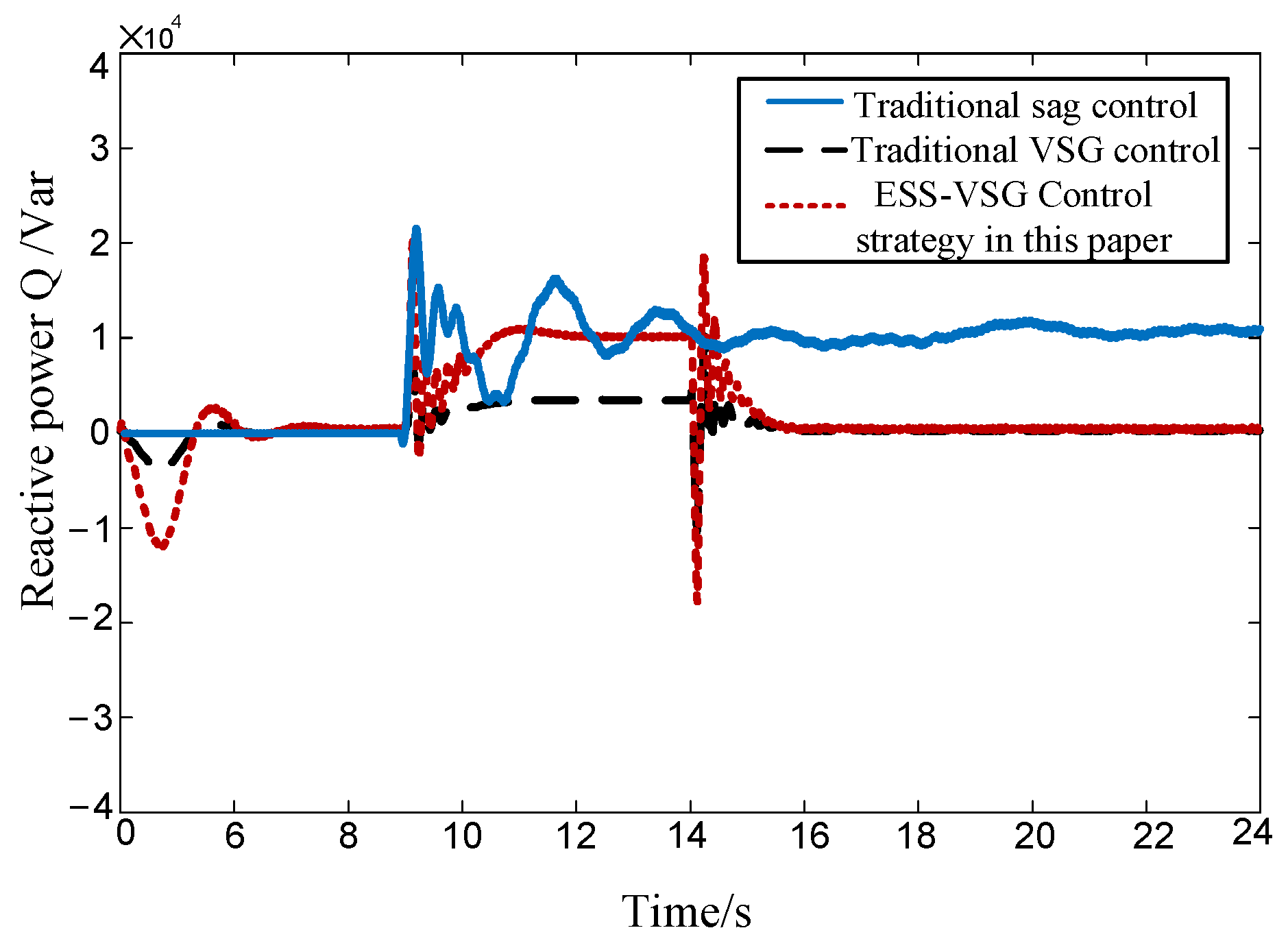
As can be seen from
Figure 11, the traditional sag control has a low reactive power compensation capability, cannot achieve low voltage ride-through, and has a slow active power recovery response after fault clearance. The traditional VSG control can effectively reduce the magnitude of voltage fluctuations and bring them back to rated values quickly and provides 2 kVar of reactive power support to the network side during a fault, but its slow power loop response results in a long overall power adjustment time, and the active power output from the VSG cannot reach the commanded value
.
Compared to the other two control methods, the control strategy proposed in this paper enables the reactive power and active power to be set according to the reactive current requirement, providing a given 10 kVar reactive power support to the network side, and the output current transient and steady-state values are not overcurrent, ensuring continuous grid-connected operation of the virtual synchronous generator while ensuring the three-phase balance of the output current. Due to the inclusion of the PI link, the reactive current response time is less than 20 ms and is quickly stabilized within 0.05 s. The active power dip is controlled by resetting the power reference value of VSG to within 20 kW, which enhances the ability of VSG to support the grid voltage and low-voltage ride-through.
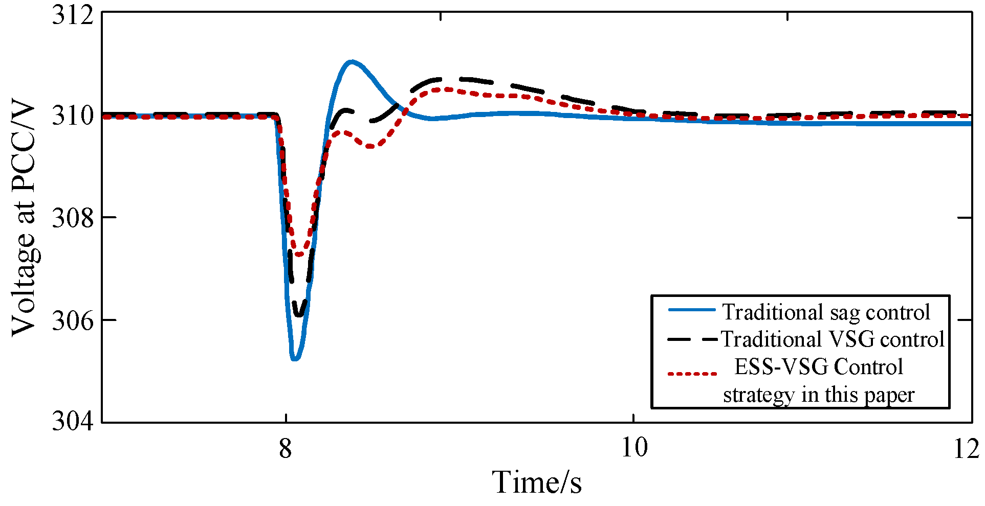
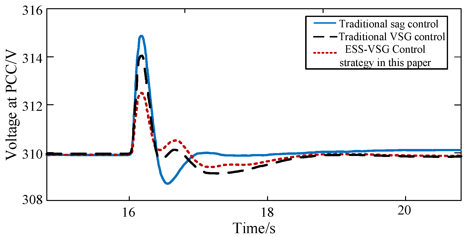
The PCC voltages in
Figure 12 and
Figure 13 show that under conventional sag control, the voltage fluctuation is about 5.4 V at fault and 4.3 V at recovery; when conventional VSG control is used, the voltage fluctuation is about 4 V when the load is connected and 4 V when the load is disconnected and about 2.8 V and 2.6 V, respectively, when the improved voltage control loop–ESS-VSG control is used. It can be seen that compared to the unimproved VSG control, the improved strategy can reduce the voltage variation by 30% and 35%, respectively, and the AC bus voltage can be recovered within 1 s. In other words, the system can be quickly restored to stability under load fluctuations.
5.2. Transient Stability Analysis Based on MPC-VSG System
In order to verify the synchronous and stable operation capability of the VSG during transients, this section uses three methods to verify the conventional VSG control, virtual impedance VSG control, and the comprehensive current-limiting VSG control, respectively, and provides a comparative analysis of the VSG command tracking effect as well as the transient current suppression effect.
First, we set the PCC to have a voltage dip fault at 0.5 s and set the inverter to withstand a steady-state current of 25 A (1.1 pu) and a maximum inrush current of 30 A (1.3 pu), with a minimum reactive current of 15 A to be injected when the grid dips by 0.5 pu, according to the national standard. [
30].
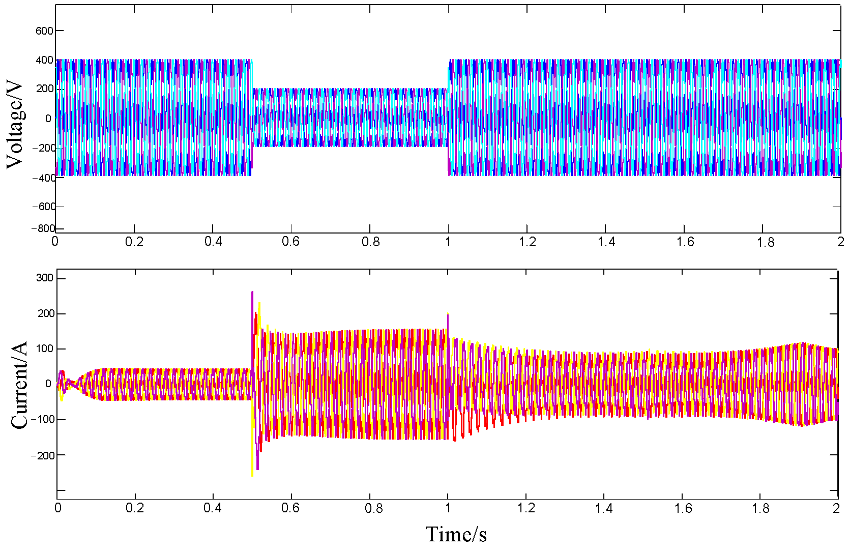
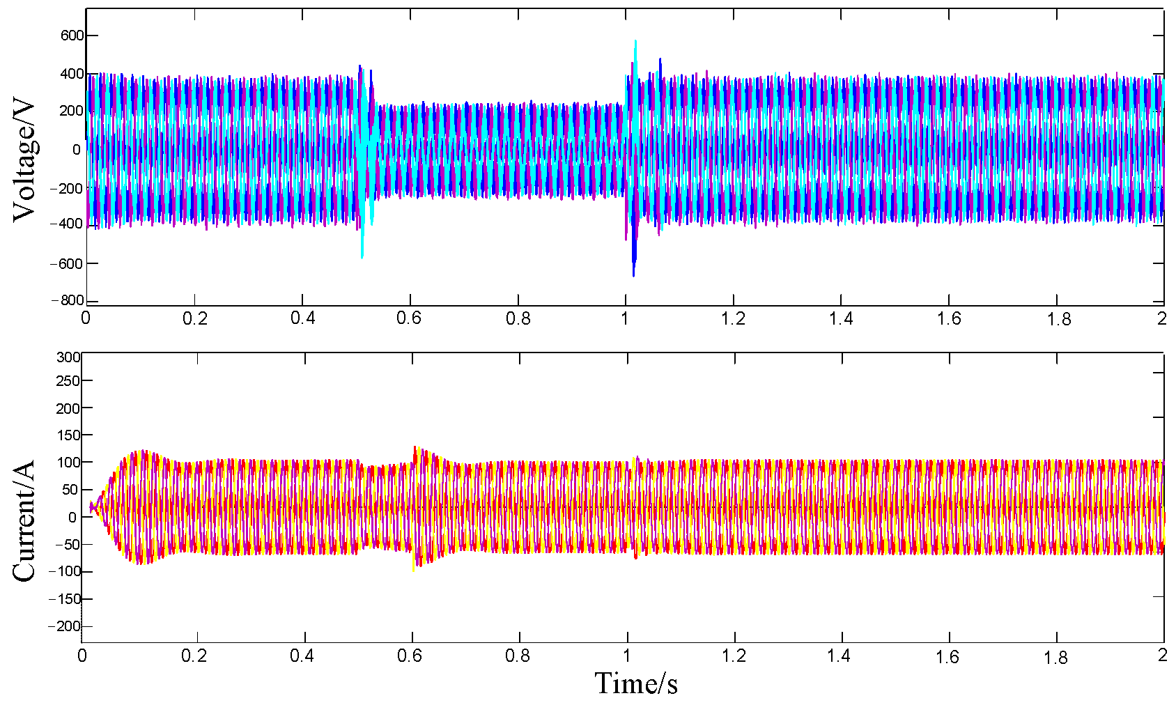
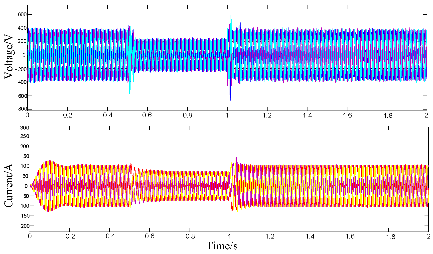
Figure 14,
Figure 15 and
Figure 16 show the output voltage and current waveforms of the grid-connected inverter under traditional VSG control, VSG control, with virtual impedance and improved VSG control during symmetrical faults. The output current of the VSG reached 150 A, which is far above the rated capacity and cannot suppress the overcurrent, and here, is a problem of current oscillation out of step after a fault occurs, causing serious damage to the network side and the own-power electronics of VSG, which cannot meet the LVRT requirements. The VSG control with virtual impedance limits the fault current by setting the virtual impedance to R
v = 7.4 Ω and L
v = −1.8 mH. As can be seen in
Figure 16, the fault current is almost stable at around 100 A, and the system remains relatively stable, but the transient inrush current is not suppressed at the time of the fault, resulting in a current limit of 40 A being exceeded. This still has an impact on the synchronization of the VSG and the stability of the system.
In contrast, this paper uses a comprehensive current-limiting method for VSG control, setting a virtual resistance current (RMS) fixed at 8.1 A (1.35 times the rated current) and a phase current-limiting current (RMS) fixed at 7.8 A (1.3 times the rated current) while maintaining the same virtual impedance settings, effectively limiting the fault current and keeping the output current amplitude within 100 A and without problems such as oscillation and misalignment. Thus, the three-phase balance of the output current is ensured.
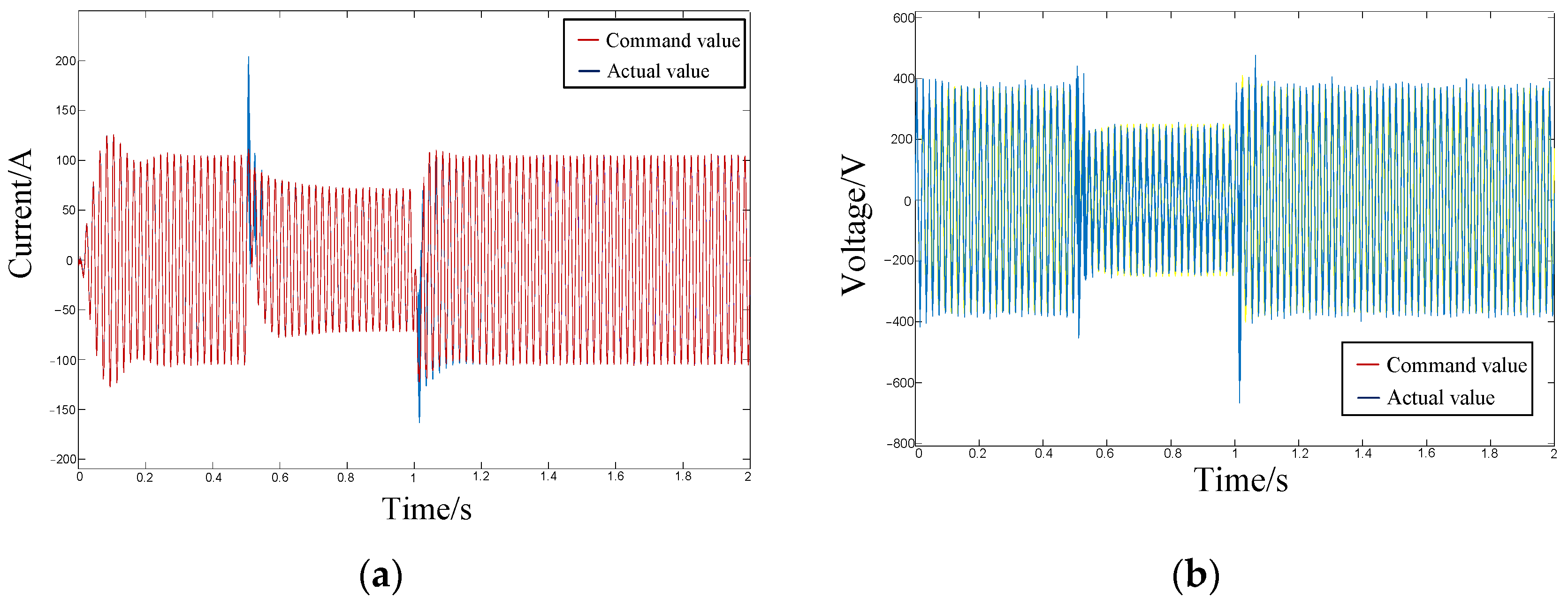
Figure 17 shows the network-side voltage and current command tracking characteristics under VSG control of the improved virtual synchronizer under symmetrical faults. The VSG accurately tracks the voltage and current reference command values in real time during this period, with the reference and actual quantities remaining in line, thus maintaining the excellent dynamic support characteristics of the VSG.


