Article

Determining and Verifying the Operating Parameters of Suppression Nozzles for Belt Conveyor Drives

by
Dominik Bałaga
1,*,
Marek Kalita
1,
Michał Siegmund
1,
Krzysztof Nieśpiałowski
1,
Sławomir Bartoszek
2,
Piotr Bortnowski
3,
Maksymilian Ozdoba
3,
Andrzej Walentek
4 and
Bożena Gajdzik
5
1
Division of Machines and Equipment, KOMAG Institute of Mining Technology, Pszczyńska 37 Street, 44-101 Gliwice, Poland
2
Division of Mechatronic Systems, KOMAG Institute of Mining Technology, Pszczyńska 37 Street, 44-101 Gliwice, Poland
3
Department of Mining, Faculty of Geoengineering, Mining and Geology, Wrocław University of Science and Technology, Na Grobli 15 Street, 50-421 Wrocław, Poland
4
Department of Extraction Technologies, Rockburst and Risk Assessment, Central Mining Institute, Plac Gwarków 1, 40-166 Katowice, Poland
5
Department of Industrial Informatics, Silesian University of Technology, Krasińskiego 8 Street, 40-019 Katowice, Poland
*
Author to whom correspondence should be addressed.
Energies 2023, 16(16), 6077; https://doi.org/10.3390/en16166077
Submission received: 28 July 2023 / Revised: 14 August 2023 / Accepted: 17 August 2023 / Published: 20 August 2023
(This article belongs to the Special Issue Energy Security and Just Transition)

Abstract

:
Drives in belt conveyors are critical components of the conveyor system, susceptible to various factors that can cause disruptions and energy losses. In underground mining conditions, the risk of drive fires is particularly hazardous. Therefore, it is necessary to develop highly effective fire suppression systems. However, there are no guidelines for designing such systems. This study presents a methodology for selecting and verifying the fire suppression systems for belt conveyor drives. The proposed AMIGA system for extinguishing fires on underground coal mine conveyor belts, incorporating spraying and water mist installations, is supported by a theoretical calculation methodology. This enables determining the number of required nozzles and flow rate for complete fire suppression. The development of a methodology for the selection and verification of the sprinkler system components utilized guidelines provided in the standard VdS 2109:2002-03 and the PN-EN 12845+A2 standard from 2010, while a novel approach is proposed for water mist parameters that has not been previously applied anywhere else, and is based on assessing the fire’s intensity and the persistent disruption of the energy balance of the combusted coal. The theoretical calculations for potential fire power facilitate the determination of the appropriate water flow rate for the spraying system to protect the upper belt drive. For the proposed AMIGA system, the potential fire power was calculated to be 10.33 MJ / min . Based on this, the water flow rate for the spraying installation to protect the upper drive belt of the conveyor was established to be a minimum 37.5 dm 3 / min , and 21.4 dm 3 / min for the mist installation used to protect the space below the conveyor drive. In order to verify the developed methodology for parameter selection, on-site tests were conducted to verify the results. Tests were conducted on an AMIGA prototype suppression system integrated into a conveyor drive. The results demonstrate that the developed system is effective in extinguishing fires on the belt using the spraying installation, as well as under the conveyor belt drive using the water mist installation, within the entire supply pressure range ( 0.4 MPa to 1.6 MPa ).

1. Introduction

Belt conveyors are one of the most crucial ways of transporting bulk materials in the mining industry [1]. Despite having the best energy efficiency among all transportation devices [2,3], the electrical energy consumption associated with transportation accounts for over 20% of the total energy consumption in the mining sector [4]. This phenomenon can be attributed to the fundamental role played by the electric motor, which serves as the cornerstone of every conveyor drive system [5]. As the drive system itself represents a critical component within the overall structure, it requires the implementation of a specialized and highly efficient monitoring system [6]. Only by adopting such an approach can uninterrupted production be ensured, and damages to the drives and power supply networks can be eliminated. To meet the demands of the market, the energy and mining sectors are progressively introducing new technical solutions [7], with a significant emphasis on ensuring adequate safety and stability within mining facilities [8,9].
Fire poses one of the primary hazards to conveyor belts, encompassing not only the drives but also the entire structures [10,11]. The probability of conveyor fires is heightened by the expansive nature of conveyor systems [12], complex routing, and demanding working conditions arising from substantial mechanical loads and aggressive work environments [13]. The electric drives of conveyors undergo continuous exposure to substantial forces and torques, resulting in mechanical overloads [14], vibrations [15], material wear [16], and, notably, overheating [17]. Another notable threat arises from the possibility of damaging the power supply network or encountering temporary disruptions in the quality of the supplied electrical energy [18]. The existence of moisture, dust, extreme temperatures, and exposure to chemical substances presents additional challenges associated with potential corrosion and water condensation. These factors pose a hazard to the sealing elements and bearing systems of the drive units, thereby increasing the risk of fire that may arise from their malfunction or failure [19]. A conveyor fire can arise not only due to the failure of drive unit components but also as a result of problems in other subsystems. Excessive friction in idler bearings [20], the contact between the belt and idlers, or the interaction between the belt and the side structure of the conveyor route can be particularly dangerous [21]. While regular maintenance and continuous monitoring of operations serve as the most effective and common preventive measures, it is. However, these measures cannot fully eliminate the risk [22,23].
Working in underground coal mines presents challenging conditions, including limited ventilation [24], high concentrations of explosive coal dust [25], and hazardous gases [26]. In such circumstances, fires can spread rapidly and hinder firefighting efforts. Additionally, the dynamics of a fire in the confined space of an underground mine further complicate the situation [27]. As a result, stringent requirements are imposed on the effectiveness of fire suppression systems. All components of conveyor drives operating in explosion-prone and fire-prone areas of underground coal mines are subject to rigorous ATEX regulations [28]. Despite this, there is a need for fire protection systems on conveyor belts, which are legally regulated through laws and regulations specific to each country [29,30,31,32]. The provisions outlined in these documents concerning conveyor belts operating in underground coal mine workings specify the design and location of each element of the fire suppression system. This includes the precise placement of temperature detection sensors and the arrangement of the suppression system. However, due to references to outdated fire suppression systems indicating specific placement conditions for sensors or extinguishing type (water-based), they impede the implementation of newer and more effective solutions, such as water mist systems, which are increasingly being used in other industrial sectors [33,34,35]. Additionally, despite numerous guidelines, these regulations do not provide any specific standards and power supply parameters that should be adopted for their development.
In underground mines, water-based fire suppression systems are commonly used, which can include spraying installations [36], water mist systems [37], or water spraying devices. The choice of an appropriate fire suppression system in mines depends on various factors such as the type of combustible materials, environmental conditions, local regulations, and safety standards, and the specific characteristics of the workplace [38]. In each case, proper analysis and risk assessments are necessary to tailor the fire suppression system to the mining conditions [39]. Water-based systems are popular due to their high effectiveness in extinguishing fires, reliability, easy access to the extinguishing medium, and low costs [40]. Water, as the extinguishing medium, is also safe for personnel, which is important in underground coal mines. Compared to the typical water-based firefighting system, the water mist systems offer additional advantages. Water mist has the ability to suppress fires more rapidly [41]. The fine water droplets in the mist have a larger contact surface area with the fire, accelerating the extinguishing process [42]. The mist is quickly dispersed and spreads around the fire [43]. The finely dispersed water droplets minimize the risk of damage to electrical and electronic equipment from water exposure [44], making water mist systems suitable for areas near conveyor drive operations.
The article presents and discusses a fire suppression system called AMIGA, designed to protect the drive and transfer points of a conveyor belt. The developed solution involves a new approach to fire suppression using water spraying and water mist installations, which is a novelty in the context of underground mining in Poland, particularly with regard to prevailing regulations. During the research on the system, a new methodology for selecting and verifying water flow rates was developed, based on VdS 2109:2002-03 standards [29] and PN-EN 12845+A2 standard from 2010 [30] for the spraying component. Additionally, the authors’ calculations for selecting the mist nozzle dimensions were developed based on the sustained disruption of the fire’s energy balance, a method not previously employed. As a result of testing, the system was successfully verified using the specially designed testing setup, allowing for the simulation of fire in an environment closely recreating the real conditions of underground coal conveyor systems. The presented results address gaps in the current regulations regarding the use of water mist installations for the analyzed mine conditions.

2. Materials and Methods

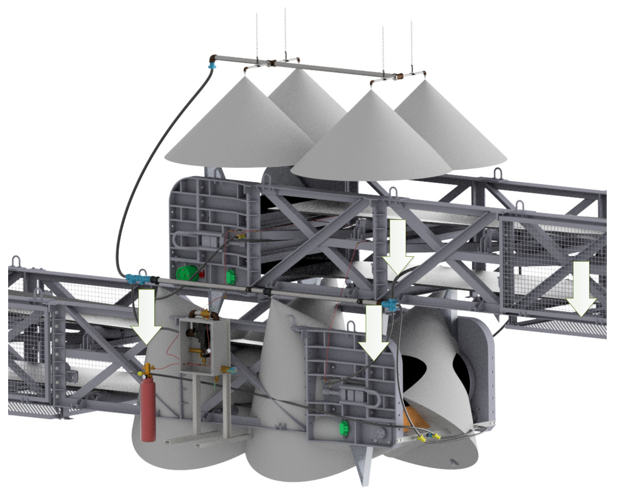
2.1. Construction of the AMIGA Fire Suppression System

The fire suppression system for belt conveyors AMIGA is designed to rapidly detect the source of fire using a detection line located at potential fire locations. It consists of two main components aimed at the fastest possible fire suppression. The first component is a set of spraying nozzles installed externally at the drive or the conveyor transferring point. The second component is a set of nozzles located inside the drive station or return end of the conveyor. The structure of the system is shown in Figure 1.
Undoubtedly, a significant advantage of the developed solution is the continuous monitoring line and the use of two types of fire suppression systems (water spraying and water mist), which enhances the likelihood of promptly detecting and extinguishing the fires. Unfortunately, the solution also has its limitations, such as the need for a continuous water supply to the system from the fire water pipeline, the requirement to adapt the solution to the design of a given conveyor system, and a more complicated maintenance process compared to the previously employed methods.
The developed fire suppression system is equipped with a set of nozzles, whose task is to provide additional protection for the drive and to transfer points of the conveyor belt where the spraying installation may not reach (e.g., under the conveyor belt). The mist installation also secures the material transfer points (discharge of the conveyor belt together with the receiving conveyor end). Flat stream nozzles with a 90° spray angle were used to protect these areas, ensuring the optimal use of the spraying stream at potential fire initiation points according to the design assumptions. The second type of nozzle used to protect the drive, discharge, and the lower part of the conveyor end (where flammable material may accumulate) is water nozzles with a cone spray pattern and a 30° spray angle. The arrangement of the mist nozzles is shown in Figure 2.
There are many types of water spraying and water mist nozzles that can be used in fire protection: for extinguishing and suppressing fires, cooling structures, preventing re-ignition, and cleaning the air from combustion products. The decision to use specific nozzles for firefighting is influenced by the following factors: spraying intensity or flow rate, the angle of the spraying cone, the distribution uniformity of spraying intensity, low sensitivity to pressure changes, repeatability of water flow parameters, spraying spectrum, reliability of operation, and cost-effectiveness. The selected water nozzles (spiral) for the fire suppression system have certain limitations, such as the limited axial range of the stream throw due to energy loss caused by the stream hitting the deflector. On the other hand, mist nozzles, in which drops breakup starts inside a few millimeters opening of the nozzle, work most efficiently at higher pressures [45]. Therefore, it was important to develop a methodology for their selection and subsequently verify it in a testing rig.

2.2. Methodology for Determining the Parameters of Extinguishing Nozzles

For the system where such a solution has not been previously implemented, theoretical calculations were performed to determine the water flow rate and the required number of nozzles to achieve its full effectiveness in suppressing the potential fire. The calculations were conducted separately for the sprinkler part and the mist nozzle part. The methodology for selecting the water parameters for the spraying part was based on the standards [29,30]. For the water mist part, a completely new methodology for determining and selecting the water parameters was developed. The spraying part of the system was constructed with an extinguishing pack of spiral nozzles with a 90° water spray angle. The spraying nozzles were positioned at a height of 1000 mm from the top edge of the conveyor drive. That means that the spraying coverage area of such a nozzle was 3.14 m 2 , which is smaller than the maximum area of 12 m 2 for this type of nozzle. Hence, the spraying intensity was nearly four times greater. The outline of the transfer station in a top view was 3000 mm × 2500 mm, and the four nozzles used were spaced at distances of 2 m from each other. The design of the system is illustrated in Figure 3.
For the proposed nozzle arrangement, the actual extinguishing area ( F r e a l ) for one nozzle was determined. The protected surface area ( P p ) covered by four nozzles can be calculated to the following formula below:
P p = a · b = 2.5 · 3.0 = 7.5 m 2
where a, b are the dimensions of the sides of the drive [m].
For a given area, the following actual extinguishing area covered by a single nozzle was determined:
F r e a l = P p n n = 7.5 4 = 1.875 m 2
where n n is the number of extinguishing nozzles.
The determined area is smaller than the maximum area for a single sprinkler, which is 12 m 2 . Therefore, the minimum flow rate intensity q t for a single nozzle is equal to:
q t = I · F r e a l = 5.0 · 1.875 = 9.375 dm 3 min
where I is the fire extinguishing intensity according to the standard [29] [mm/min].
The flow rate result from a single nozzle is 9.375 dm 3 / min , so it is necessary to check if the selected nozzle meets this requirement and at what water pressure. Due to the fact that the manufacturer does not provide the constant flow rate K for the selected nozzle, it needs to be determined using the following formula:
K = Q p = 10.3 3 = 5.94 dm 3 · bar min
where Q is the nozzle flow rate [dm3/min], p—pressure [bar].
The minimum required pressure at the nozzle to achieve the minimum flow rate of a single nozzle is calculated using the following formula:
p t = q t K 2 = 9.375 5.94 2 = 2.49 bar .
Due to the fact that the minimum flow rate of the nozzle is achieved at a pressure of 0.249 MPa, it can be concluded that pressures lower than 0.4 MPa (the minimum pressure required by regulations in the fire protection pipeline in Polish coal mines [31]) and higher than 0.15 MPa (the pressure required by the design standard [30] for nozzles) are met. Therefore, it can be considered that the selected nozzles installed above the drive meet the design requirements according to the VdS guidelines [29].
Determining the operating parameters for the used mist nozzles proved to be more challenging, as there are no specific guidelines for designing fire suppression systems with such nozzles. According to the National Fire Protection Association [46], water mist is defined as a dispersed water stream with droplet sizes that are 90% or 99% (depending on the convention) of its total mass smaller than 1000 µm. However, as indicated by literature analysis [47,48], and our own experiments, an effectively sustained mist in the air consists of droplets within the range of up to 100 µm. Water, due to its properties, is an excellent extinguishing agent, characterized by a high specific heat value (4.18 kJ·kg−1·K−1) and heat of vaporization (2240 kJ·kg−1). During the phase transition from liquid to vapor, it expands 1620 times in volume, displacing air from the fire area. It is assumed that when using water stream-generating nozzles, approximately 50% of the total amount of water consumed directly participates in extinguishing the fire, mainly by absorbing heat through the phase transition process.
To extinguish a fire, it is sufficient to permanently disrupt its energy balance. Because it is difficult to measure the amount of energy flowing into the liquid surface, it is considered that such a disruption of the heat transfer balance occurs when the amount of energy generated in the fire environment is less than the amount of energy absorbed by the cooling agent. The process of coal combustion can be simplified as follows:
C + O 2 CO 2
To burn 1 mole of carbon, 1 mole of oxygen is required. Considering that 1 mole of carbon (C) is equal to 12 g and the heat of combustion of carbon is Q s ( C ) = 393.5 kJ/mol, the heat of combustion of 1 kg of carbon is given by Q s ( C ) = 393.5 · 1000 12 = 32 , 790 kJ / kg . The volume of air required to burn 1 mole of coal (under normal conditions) can be described as V = 1 mol ( O 2 ) · 22.4 dm 3 / mol 0.21 = 106.6 dm 3 = 0.107 Nm 3 . Assuming that the heat required to warm up water from 20 °C to 100 °C is Q w = 2600 kJ / kg = 2.6 MJ / kg and that water fully participates in the extinguishing process, we can calculate that the zero balance condition is met when supplying 1 kg of coal with water in the amount of 32 , 790 2600 = 12.6 kg . Simultaneously, to burn 1 kg of coal, air needs to be supplied in the amount of 1000 12 · 0.107 = 8.92 Nm 3 is required.
According to the calculations, water ( 12.6 kg) needs to be suspended in the form of mist in ( 8.92 m3) of air, which means that the optimal water concentration in the mist is 1.41 kg/m3 for the combustion of pure coal. This implies that even an air stream containing water mist with a weight ratio of water to air of approximately 1:1.2 exhibits extinguishing properties. Depending on the fire’s power, water should be supplied in an amount corresponding to the generated heat. Figure 4 presents the graph of water volume (extinguishing agent), air volume, and mass of burned coal as a function of the fire’s power.
The fire’s power that may occur in protected areas was calculated based on the Polish standard [49]. The fire load density, Q d , was calculated assuming an average layer of coal dust with a height of approximately 0.05 m on the protected surface. The bulk density of coal dust is 900 kg/m3, and the heat of combustion is Q s ( C ) = 32.8   M J / k g . Therefore, the fire load density is Q d = 32.8   M J / k g · 315   k g / 7 m 2 = 1 476 MJ / m 2 . By knowing the fire load density, the relative duration of the fire was determined from the graph shown in Figure 5, which is approximately 100 min.
Assuming that all the coal present in the protected area will burn within 100 min, the average burning rate can be calculated as v s = 315 kg 100 min = 3.15 kg / min . Hence, the fire power in the protected area is given by Q P = 3.15 kg / min · 32.8 MJ / kg = 103.32 MJ / min = 1.72 MJ / s . Assuming that the water mist can absorb heat Q w to its maximum capacity, to extinguish the fire with the determined power Q P = 103.32 MJ/min, water mist needs to be supplied with a flow rate of Q m = Q P Q w = 103.32 MJ / min 2.6 MJ / kg = 39.74 kg / min 4 dm 3 / min . Assuming that approximately 50% of the water mist actively participates in extinguishing the fire, for a fire with an average power of Q P = 10.33 MJ / min , the water mist needs to be supplied with a minimum flow rate of Q m 8 dm 3 / min . Within the protected area of the drive, the installation of 5 flat stream nozzles and 4 full cone nozzles is planned. Based on the nozzle manufacturer’s datasheets, the flow rate of water through the nozzle at a pressure of 0.25 MPa (minimum specified pressure) was selected. The total flow rate of water in the mist nozzles is presented in Table 1.
The type and number of mist nozzles used in the conveyor drive satisfy the condition of minimum water mist flow rate: Q m 8 dm 3 / min Q d 21.4 dm 3 / min . These selected nozzles have a safety factor of over 2.5 times the required amount of water for extinguishing the fire.

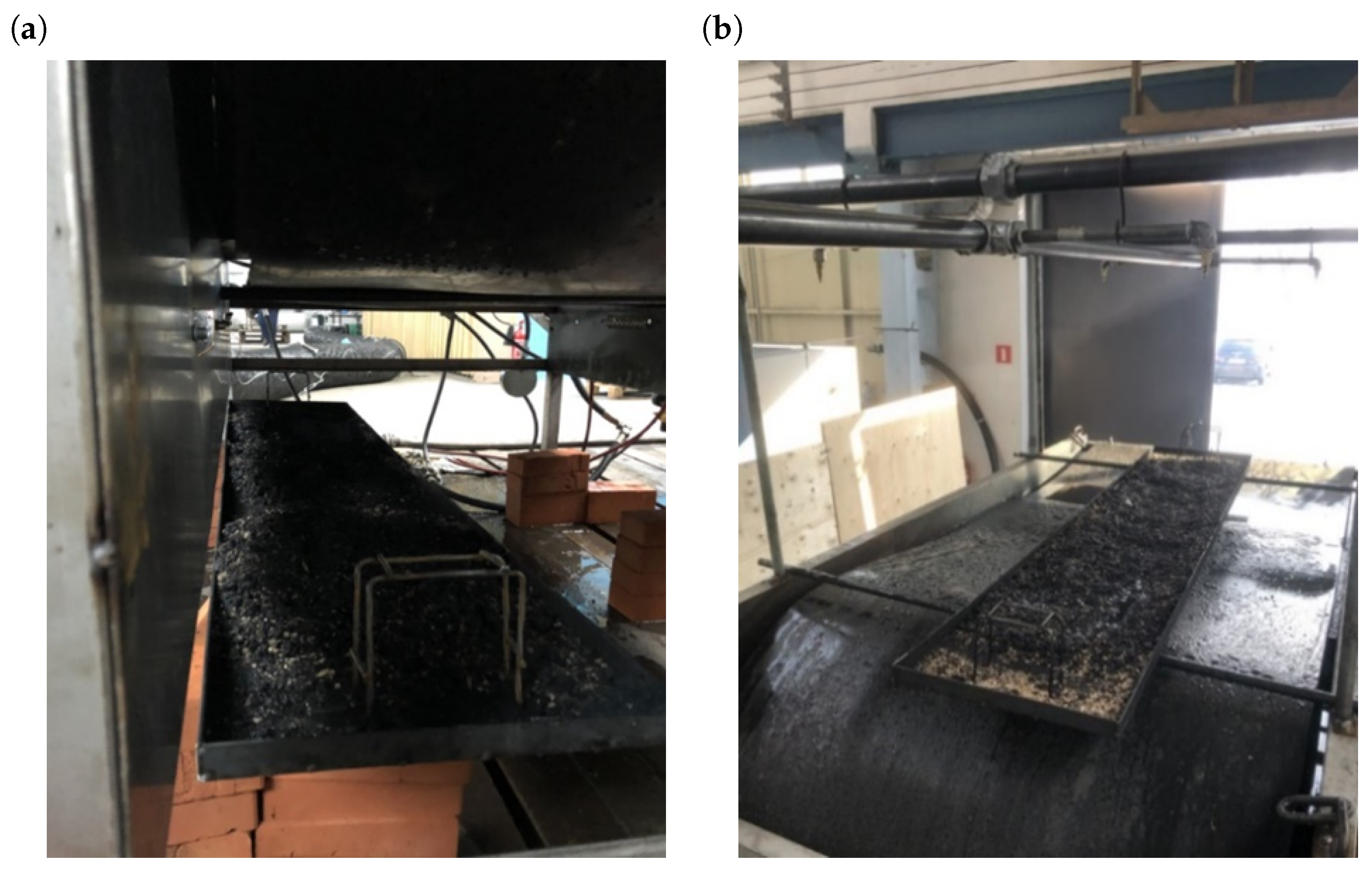
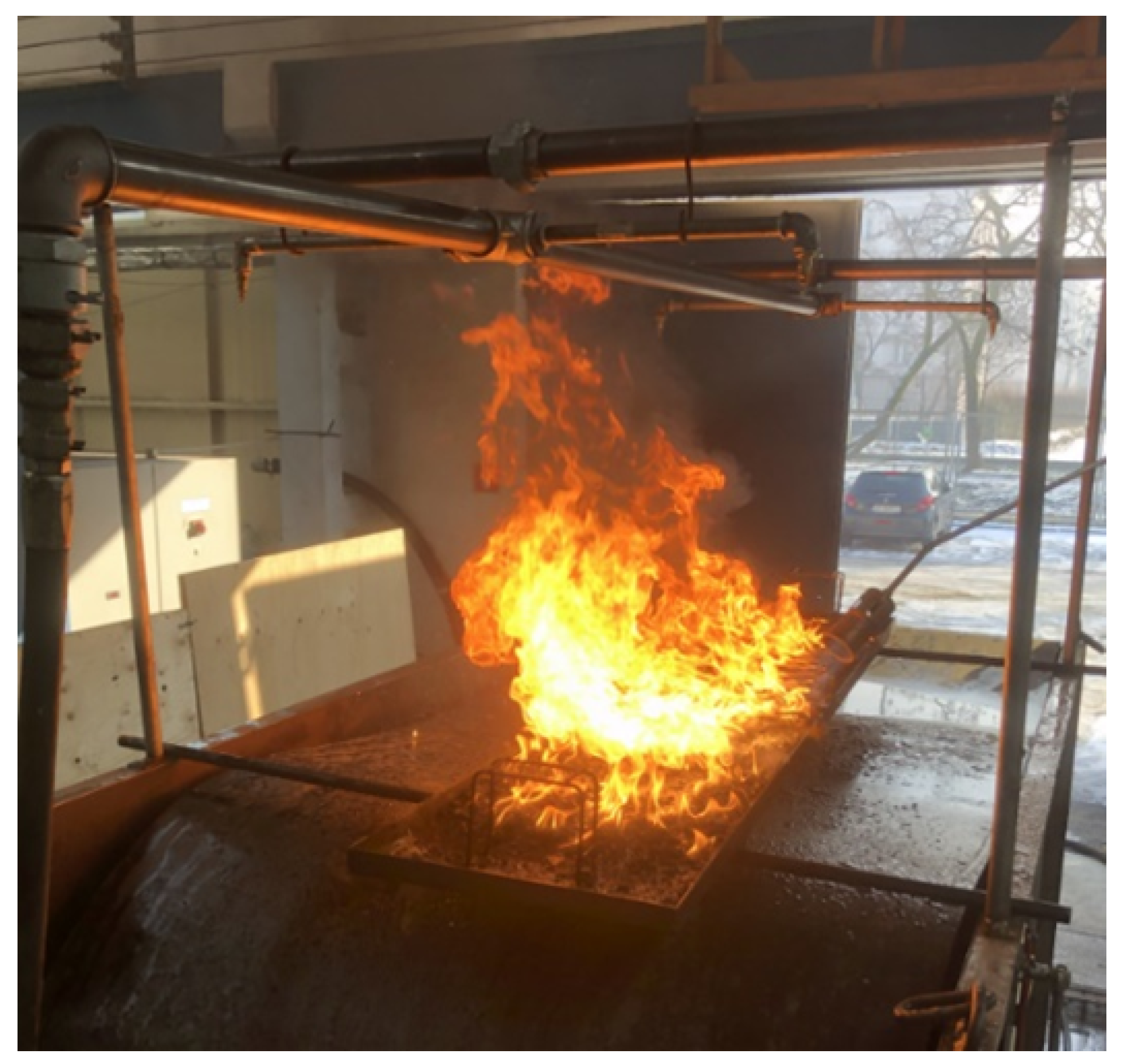
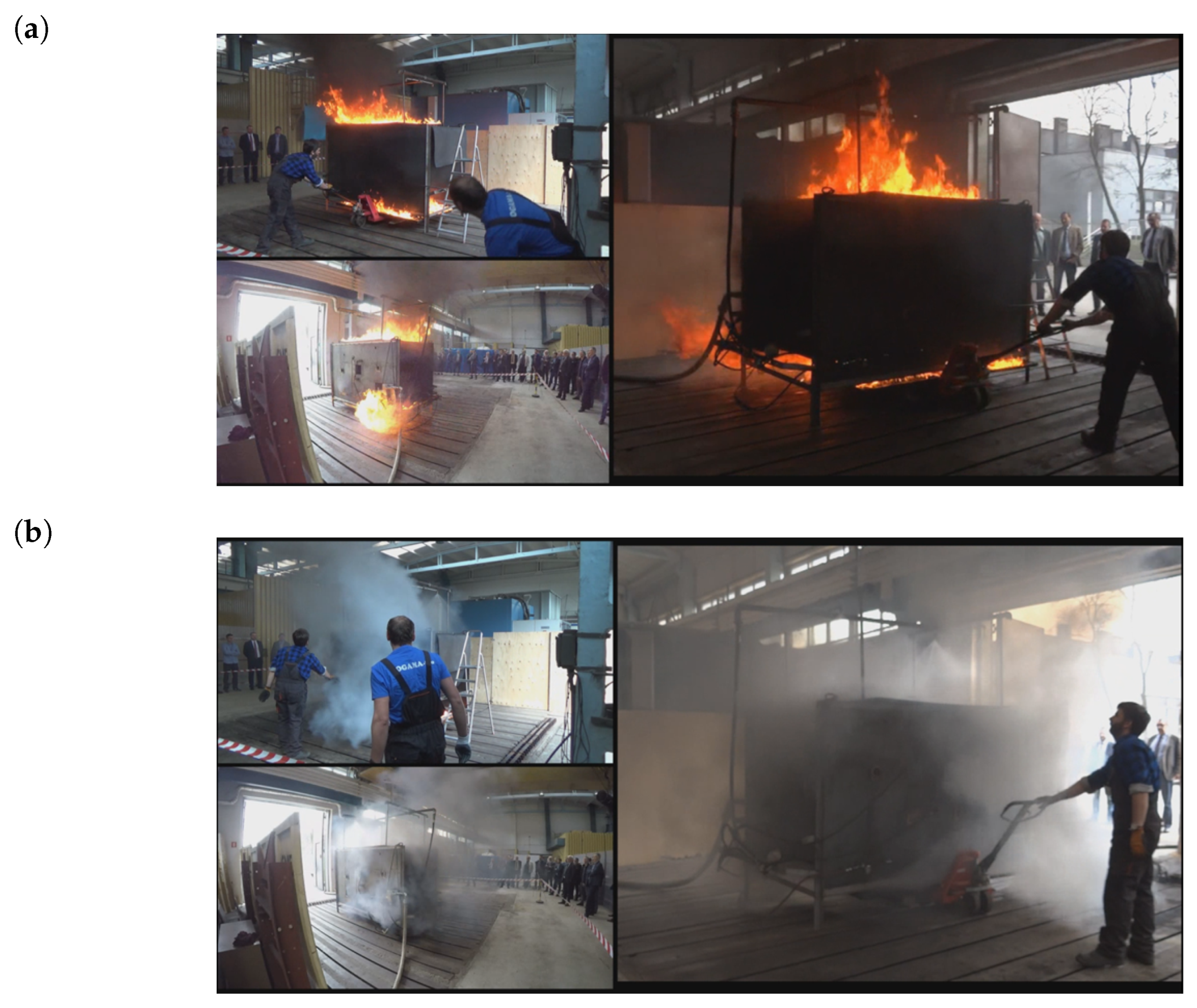
2.3. Measurement Station and Bench Tests
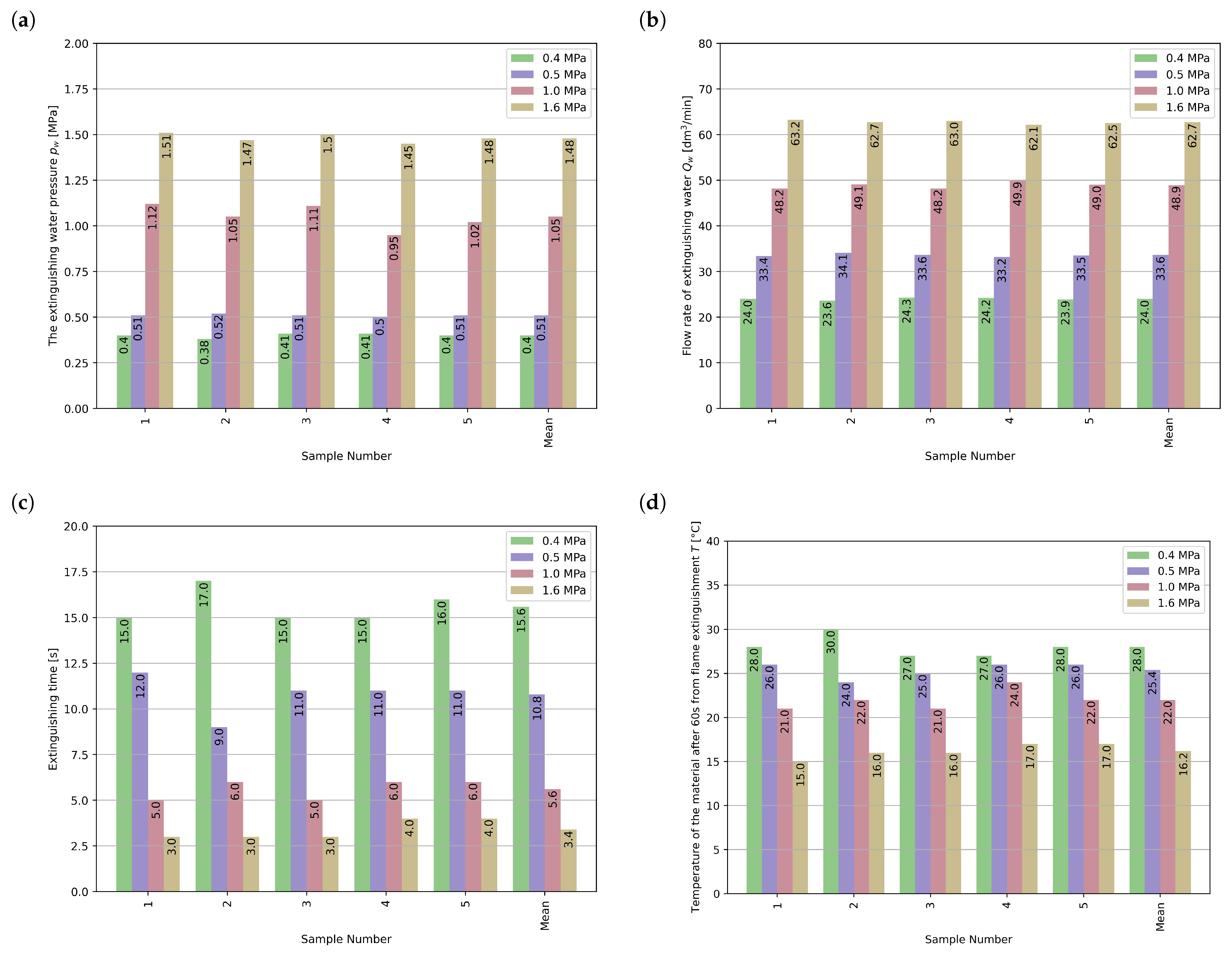
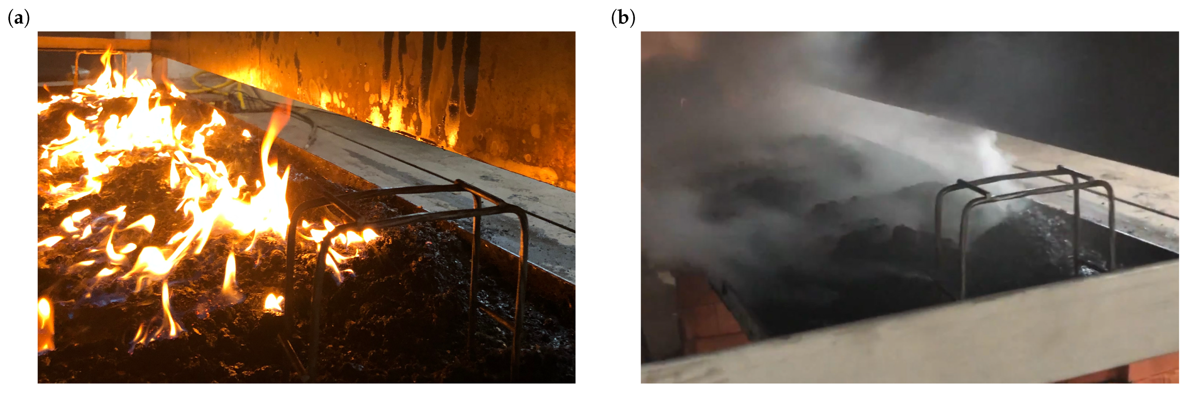
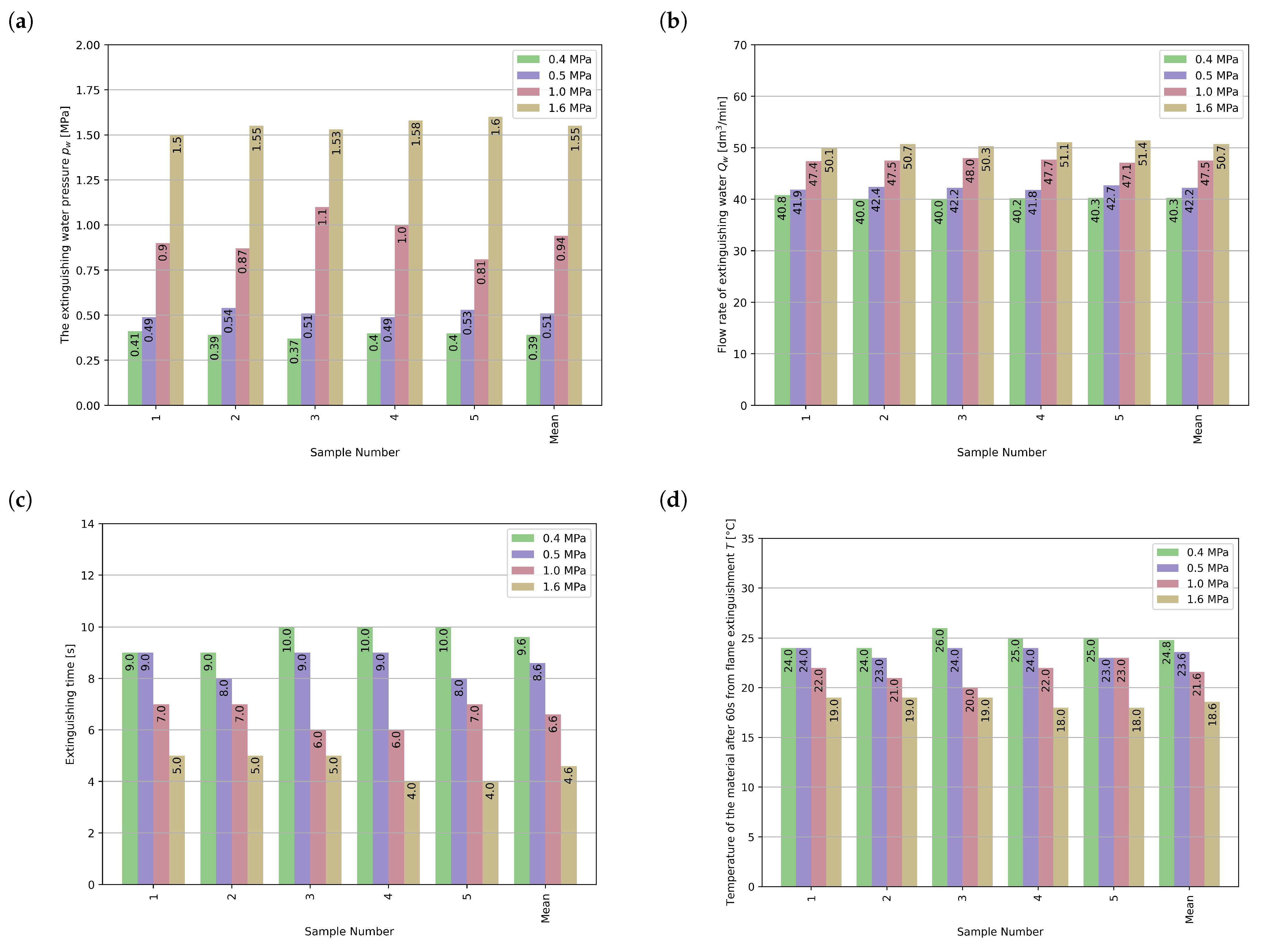
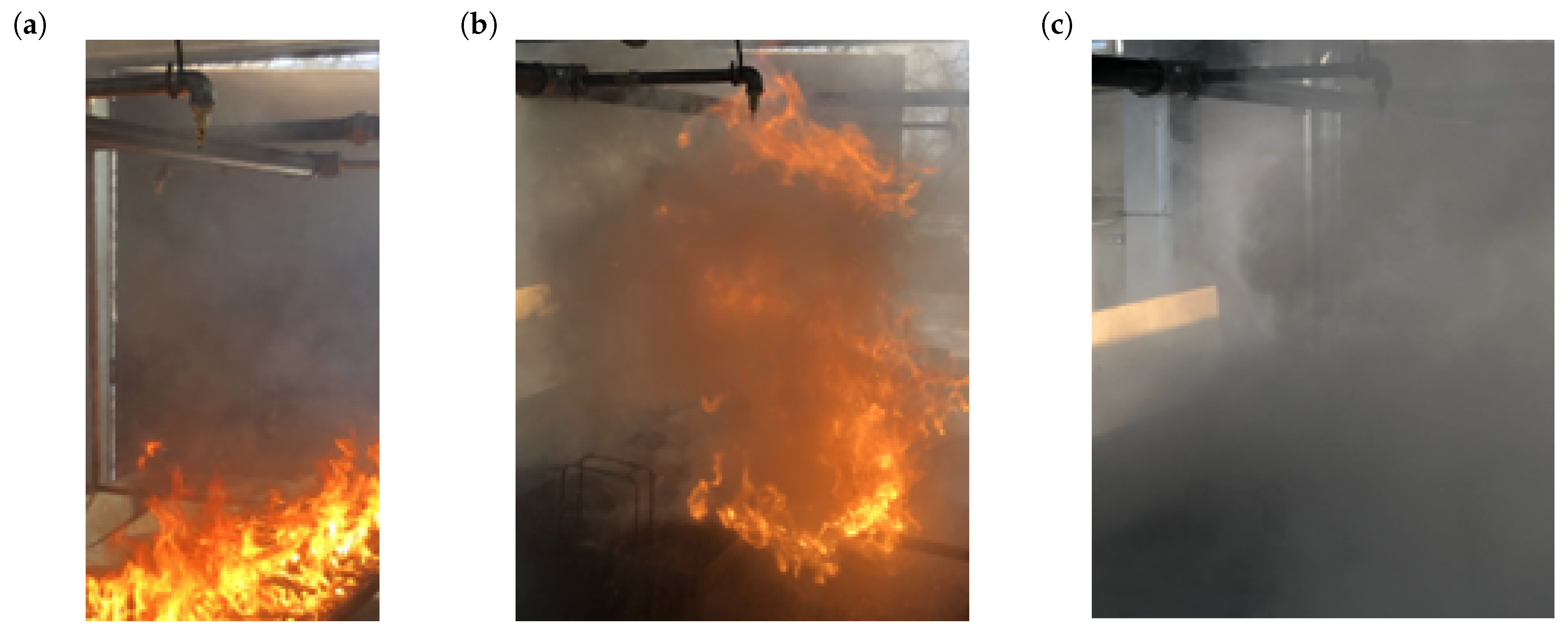
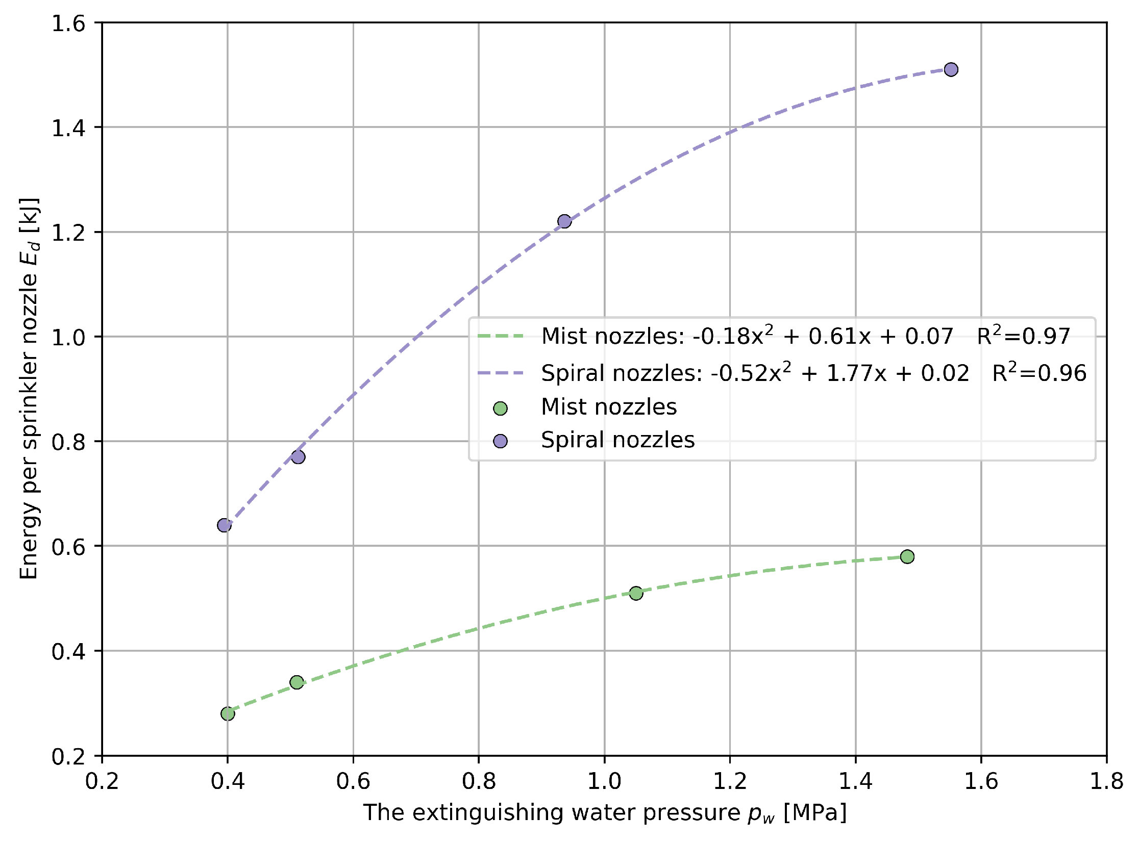
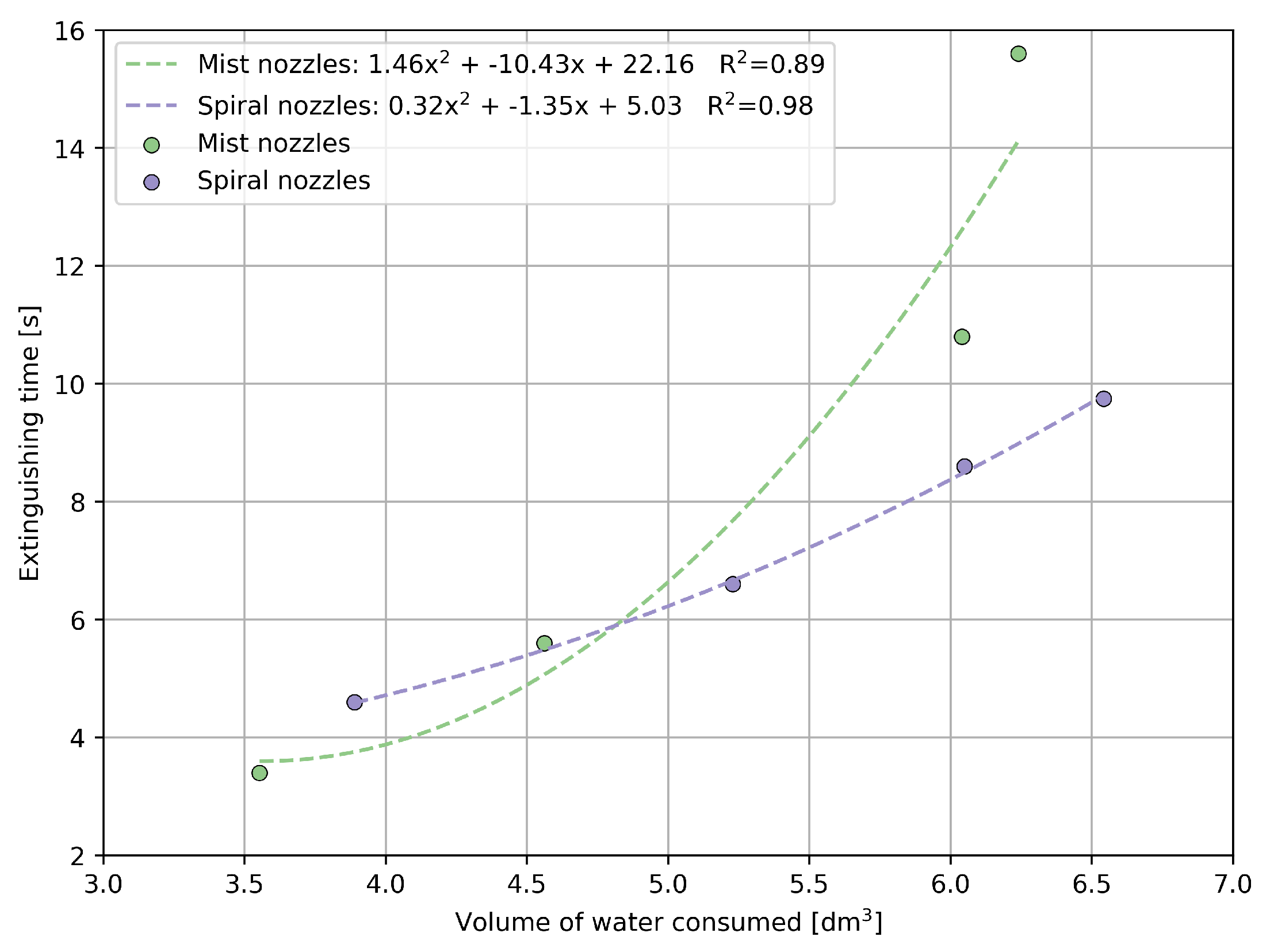
The stage of field testing aimed to validate the adopted assumptions regarding the selection of nozzles, their placement, and the methodology for determining the minimum supply parameters of the AMIGA fire suppression system. Positive results from the field testing demonstrated that the developed methodology of the fire-suppressing system confirmed its proper operation in real conditions. The analyzed AMIGA system’s effectiveness under real fire conditions was also verified. Such tests had not been conducted previously due to the lack of guidelines in the Polish regulations and a lack of information about the potential size of the fire. Of course, this required the development of an innovative measuring station to test the effectiveness of the drive extinguishing system, which was equipped with a drive model designed to faithfully replicate a real belt conveyor assembly. The drive model was constructed with two cylinders made of metal sheets (simulating the drive pulleys) placed between side walls. A conveyor belt with a width of 1200 mm was wound around the pulleys, creating a closed space (Figure 6).
The fire suppression system integrated into the drive model consisted of an internal section equipped with mist nozzles and an external section equipped with water spraying nozzles. In the front and rear sections of the model, four cone-shaped water mist nozzles were placed, safeguarding the space beneath the drive where combustible material could potentially catch fire. The area between the drum and the belt was protected using the flat nozzle. The external part of the fire suppression installation mounted on the drive model encompassed a spraying battery equipped with four spray nozzles, covering an area 3.0 m × 2.5 m of its operation.
The effectiveness of fire extinguishing was measured in two locations of a potential fire source. The fire source was placed on a special tray with dimensions of 400 × 2000 mm, underneath the drive model of the conveyor (Figure 7a), and on the upper belt of the conveyor drive model (Figure 7b).
A mixture of coal dust/coal fines was prepared for the experiments, including the use of an igniter with a mass of 0.315 kg , which was necessary to achieve firepower of 10.33 MJ / min . The prepared mixture was placed on a tray and exposed to the action of a burner until it was ignited, thus reaching self-sustained combustion of the fuel material at a given point. The effectiveness of extinguishing the burning material was determined by the time required to extinguish the ignited material on the tray, from the moment the firefighting system was activated until it was extinguished. A test was considered fully effective if, after 60 s from extinguishing, start a temperature of the cooled burned fuel bed was 30 C and no re-ignition occurred within 10 min . The extinguishing test was repeated four times (at an air speed of 3 m / s and at spray pressures of 0.4 MPa , 0.5 MPa , 1.0 MPa , and 1.6 MPa ). Such tests were performed for the burning material on the tray, located beneath the conveyor drive model (mist installation), as well as on the belt of the conveyor drive model (spraying installation). The ignition stage of the fuel mixture on the upper belt of the conveyor is shown in (Figure 8).

3. Results

The tests on the effectiveness of the mist installation under the conveyor drive model (at a water pressure of 0.4 MPa, 0.5 MPa, 1.0 MPa, and 1.6 MPa) did not exceed the set bed temperature of 30 °C after 60 s of operation. The shortest extinguishing times (3 s) were achieved at the highest water supply pressures (1.6 MPa) and a water flow rate of 213.2 dm3. The results of extinguishing the combustible material using mist cone nozzles supplied with pressures of 0.4 MPa, 0.5 MPa, 1.0 MPa, and 1.6 MPa are presented in Figure 9. The successful extinguishing attempt of the material located under the drive model is presented in Figure 10.
Similar tests were conducted to assess the effectiveness of the spraying system on the conveyor belt drive model (at a water pressure of 0.4 MPa, 0.5 MPa, 1.0 MPa, and 1.6 MPa). In one out of five attempts, at a supply pressure of 0.4 MPa, the fire was not extinguished due to the clogging of one of the spraying nozzles. In other tests, the system demonstrated 100% effectiveness. Similar to the mist system, the shortest extinguishing time (4 s) was recorded at the highest supply pressure (1.6 MPa) with a water flow rate of 233.3 dm3. The temperature of the burning material bed, measured using a thermocouple 60 s after fire extinguishment, did not exceed 30 °C in any of the tested cases. The results of extinguishing the combustible material using spiral nozzles supplied with water pressures of 0.4 MPa, 0.5 MPa, 1.0 MPa, and 1.6 MPa are presented in Figure 11. The successful attempt to extinguish the material located above the conveyor belt model is presented in Figure 12.

4. Discussion

The tests of the developed AMIGA effectiveness proved its efficiency in extinguishing fires on the belt and beneath the conveyor drive within the supply pressure range ( 0.4 ÷ 1.6 MPa ). The fire extinguishing time, depending on the fire location and water supply pressure of the system is presented graphically in Figure 13.
From the presented graph, it can be observed that up to approximately 0.8 MPa of water supply pressure, the spiral water nozzles achieve shorter fire extinguishing time. In contrast, at higher pressures, the mist nozzles operate more effectively by generating better water dispersion. This phenomenon is closely related to the kinetic energy of the droplet ejection and, consequently, the size of the droplets produced by each type of nozzle. Higher pressure supply for the mist nozzles, despite an increase in the flow rate to the nozzle, results in the formation of smaller diameter droplets with higher kinetic energy, leading to faster fire suppression. Confirmation of this can be found in the calculations presented below for the energy required to generate the spray stream of each spraying installation used in the fire suppression system (Table 2). This energy is necessary to produce the flow rate and water pressure required for fire suppression within a specific time frame:
E W = V ˙ W · p W · τ
where V ˙ W is the water flow rate [dm3/min], p W is the water pressure [Pa], and τ is the operating time [min].
Additionally, the calculated water energy is presented in relation to the extinguished fire, per energy per second of system operation, and per individual nozzle.
As the results indicate, the energy required to extinguish the fire by the mist installation is lower than the energy required by the spraying installation for comparable ranges of water supply pressure (Figure 14). At the same time, the results of the energy per single spraying nozzle indicate that the energy of the mist nozzles within the range of supply pressure is lower than the energy of the spraying nozzle.
An important aspect of tests was to achieve a temperature of the burning material after it is extinguished lower than 30 °C to eliminate fire re-ignition. The graph below presents the temperature of the burning material bed after it is extinguished and an after additional 60 s of spraying (Figure 15).
On the graph, it is noticeable that the lowest temperature was measured for the mist nozzle, at its highest water consumption, which is a natural phenomenon. The mist nozzle extinguished the fire faster and consumed less water during the extinguishing of the fire; the lower temperature can result from its lower variability water flow. This is also evident in the results of the extinguished burning material temperature. The water volume used for fire extinguishing by each spraying system and the extinguishing time is presented in the figure below (Figure 16).
The graph shows that the extinguishing time of the fire is not only determined by the amount of water used but also by its energy and the degree of drop atomization. The presentation of fire suppression in both the lower and upper sections of the conveyor drive, conducted in the testing room, is given in Figure 17.

5. Conclusions

The increase in efficiency of coal-carrying belt conveyors brings higher risk, especially fire hazards. This requires the use of newer and more effective fire protection systems. Unfortunately, existing guidelines for designing such systems for belt conveyors are not updated, leading to difficulties in implementing more popular water mist fire suppression systems. At ITG KOMAG, a methodology for selecting and verifying the water flow rates (exemplified by the AMIGA fire suppression system) was developed based on the type of fire suppression used (spraying water nozzles and water mist nozzles), supported by testing and successful validation of the system on a specially designed testing facility. While working on the methodology for selecting the water mist nozzles for the fire suppression system, the potential fire power was determined, calculated to be 10.33 MJ / min . Following the adopted and developed methodology for selecting the flow rates of spraying nozzles, a water flow rate of 9.375 dm 3 / min was determined for the spray nozzle protecting the upper drive belt of the conveyor, and 8 dm 3 / min for the water mist nozzles used to protect the space beneath the conveyor drive.
To verify the water parameter selections for both spray and mist suppression, tests were conducted on the prototype AMIGA system designed to protect the drive and transferring points of belt conveyors. Positive results from the field testing demonstrated that the developed methodology of the fire-suppressing system confirmed its proper operation in real conditions. The analyzed AMIGA system’s effectiveness under real fire conditions was also verified. The tests were carried out on a specially designed testing setup equipped with a drive model that closely recreated the real conveyor assembly.
Such tests had not been conducted previously due to the lack of guidelines in the Polish regulations and a lack of information about the potential size of fire.
The test results indicate that both the spraying system (above the belt) and the mist system (below the drive) exhibited complete efficacy in fire suppression within the entire range of supply pressure ( 0.4 ÷ 1.6 MPa ). Consequently, the tests validated the determined water flow rates that effectively extinguish fires within the system. The tests revealed that employing mist nozzles at supply pressures exceeding 0.8 MPa resulted in shorter fire suppression times due to better droplet atomization, facilitating heat absorption from fire. The analysis of water energy demonstrated that the energy required to extinguish fire using the mist system is lower than that required by a spiral system within comparable supply pressure ranges. At the same time, the results of the energy per single spraying nozzle indicate that the energy of the mist nozzles within the range of supply pressure is lower than the energy of the spraying nozzle.
In summary, the developed methodology for the determination of water flow rates in underground mine fire extinguishing systems using the spiral and mist nozzles proves to be highly effective and enables these systems’ implementation in alignment with fire protection regulations. It becomes a noteworthy guide to the existing design standards of fire extinguishing systems in underground coal mining. The future directions for improving the solution cover an economic analysis of the proposed fire suppression system solutions, considering an algorithm for selecting them depending on the specific working conditions.

Author Contributions

Conceptualization, D.B. and M.S.; methodology, D.B. and M.S.; formal analysis, D.B., K.N. and M.K.; investigation, S.B.; data curation, D.B., M.S. and A.W.; writing—original draft preparation, M.S., K.N. and P.B.; writing—review and editing, M.O. and M.K.; visualization, S.B., K.N. and P.B.; supervision, P.B., M.O. and B.G.; project administration, D.B. and B.G. All authors have read and agreed to the published version of the manuscript.

Funding

The research was financed from ITG KOMAG’s own funds.

Institutional Review Board Statement

Not applicable.

Informed Consent Statement

Not applicable.

Data Availability Statement

Samples and calculation results are available from the corresponding author upon email request.

Conflicts of Interest

The authors declare no conflict of interest.

References

  1. Braun, T.; Hennig, A.; Lottermoser, B.G. The need for sustainable technology diffusion in mining: Achieving the use of belt conveyor systems in the German hard-rock quarrying industry. J. Sustain. Min. 2017, 16, 24–30. [Google Scholar] [CrossRef]
  2. Zhang, S.; Xia, X. Optimal control of operation efficiency of belt conveyor systems. Appl. Energy 2010, 87, 1929–1937. [Google Scholar] [CrossRef]
  3. Mathaba, T.; Xia, X. Optimal and energy efficient operation of conveyor belt systems with downhill conveyors. Energy Effic. 2017, 10, 405–417. [Google Scholar] [CrossRef]
  4. Holmberg, K.; Kivikytö-Reponen, P.; Härkisaari, P.; Valtonen, K.; Erdemir, A. Global energy consumption due to friction and wear in the mining industry. Tribol. Int. 2017, 115, 116–139. [Google Scholar] [CrossRef]
  5. Ananth, K.N.S.; Rakesh, V.; Visweswarao, P.K. Design and selecting the proper conveyor-belt. Int. J. Adv. Eng. Technol. 2013, 4, 43–49. [Google Scholar]
  6. Schools, T. Condition monitoring of critical mining conveyors. Eng. Min. J. 2015, 216, 50. [Google Scholar]
  7. Haidai, O.; Ruskykh, V.; Ulanova, N.; Prykhodko, V.; Cabana, E.C.; Dychkovskyi, R.; Howaniec, N.; Smolinski, A. Mine Field Preparation and Coal Mining in Western Donbas: Energy Security of Ukraine—A Case Study. Energies 2022, 15, 4653. [Google Scholar] [CrossRef]
  8. Szkudlarek, Z.; Ivanova, T.N. Mechanization of cleaning the area of operating belt conveyor system. Min. Mach. 2021, 39, 2–12. [Google Scholar] [CrossRef]
  9. Nieśpiałowski, K.; Chelyadyn, L.; Romanyshyn, T. Cooling system for high-power drives in belt conveyors. Min. Mach. 2022, 40, 54–63. [Google Scholar] [CrossRef]
  10. Ray, S.K.; Khan, A.M.; Mohalik, N.K.; Mishra, D.; Varma, N.K.; Pandey, J.K.; Singh, P.K. Methodology in early detection of conveyor belt fire in coal transportation. Energy Sources Part A Recovery Util. Environ. Eff. 2020, 1–19. [Google Scholar] [CrossRef]
  11. Barros-Daza, M.J.; Luxbacher, K.D.; Lattimer, B.Y.; Hodges, J.L. Mine conveyor belt fire classification. J. Fire Sci. 2022, 40, 44–69. [Google Scholar] [CrossRef]
  12. Shijie, P.; Huang, Z.; Dong, D.W. Numerical simulation study on fire hazard of a coal mine transport roadway. Min. Sci. 2022, 29, 33–52. [Google Scholar] [CrossRef]
  13. Litton, C.D.; Lazzara, C.P.; Perzak, F.J. Fire Detection for Conveyor Belt Entries; US Department of the Interior, Bureau of Mines: Washington, DC, USA, 1991; Volume 9380.
  14. Semenchenko, A.; Stadnik, M.; Belitsky, P.; Semenchenko, D.; Stepanenko, O. The impact of an uneven loading of a belt conveyor on the loading of drive motors and energy consumption in transportation. East.-Eur. J. Enterp. Technol. 2016, 4, 42–51. [Google Scholar] [CrossRef]
  15. Homišin, J.; Grega, R.; Kaššay, P.; Fedorko, G.; Molnár, V. Removal of systematic failure of belt conveyor drive by reducing vibrations. Eng. Fail. Anal. 2019, 99, 192–202. [Google Scholar] [CrossRef]
  16. Persson, B. Conveyor belt drive physics. Tribol. Lett. 2020, 68, 1–9. [Google Scholar] [CrossRef]
  17. Chakraborty, S.; Arvind, P.; Poddar, S.; Acharya, A.K.; Kumar, S.D. Integration of IoT Based PLC for Smart Relaying of a PV-Fed Induction Motor Driven Conveyor Belt. In Proceedings of the Fifth International Conference on Microelectronics, Computing and Communication Systems: MCCS 2020; Springer: Singapore, 2021; pp. 155–165. [Google Scholar] [CrossRef]
  18. Edomah, N. Effects of voltage sags, swell and other disturbances on electrical equipment and their economic implications. In Proceedings of the CIRED 2009—20th International Conference and Exhibition on Electricity Distribution—Part 1. IET, Prague, Czech Republic, 8–11 June 2009; pp. 1–4. [Google Scholar] [CrossRef]
  19. Hamacher, S.; Hamacher, S. Common conveyor drives. In The Drum Motor: The All-Rounder in Modern Unit Handling Conveyor Technology; Springer: Berlin/Heidelberg, Germany, 2020; pp. 29–53. [Google Scholar] [CrossRef]
  20. Wijaya, H.; Rajeev, P.; Gad, E.; Vivekanamtham, R. Distributed optical fibre sensor for condition monitoring of mining conveyor using wavelet transform and artificial neural network. Struct. Control. Health Monit. 2021, 28, e2827. [Google Scholar] [CrossRef]
  21. Goldbeck, L. Improved maintenance reduces risk, raises profitability in conveyor operations. In Proceedings of the 2011 IEEE-IAS/PCA 53rd Cement Industry Technical Conference, St. Louis, MO, USA, 22–26 May 2011; pp. 1–6. [Google Scholar] [CrossRef]
  22. Cheremushkina, M.; Poddubniy, D. Reducing The Risk of Fires in Conveyor Transport. IOP Conf. Ser. Earth Environ. Sci. 2017, 50, 012043. [Google Scholar] [CrossRef]
  23. Francart, W. Reducing belt entry fires in underground coal mines. In Proceedings of the 11th US/North American Mine Ventilation Symposium 2006, Philadelphia, PA, USA, 5–7 June 2006; pp. 303–308. [Google Scholar]
  24. Cheng, L.; Ueng, T.; Liu, C.W. Simulation of ventilation and fire in the underground facilities. Fire Saf. J. 2001, 36, 597–619. [Google Scholar] [CrossRef]
  25. Ajrash, M.J.; Zanganeh, J.; Moghtaderi, B. The effects of coal dust concentrations and particle sizes on the minimum auto-ignition temperature of a coal dust cloud. Fire Mater. 2017, 41, 908–915. [Google Scholar] [CrossRef]
  26. Thakur, P. Advanced Mine Ventilation: Respirable Coal Dust, Combustible Gas and Mine Fire Control; Woodhead Publishing: Sawston, UK, 2018. [Google Scholar]
  27. Brake, D. Fire modelling in underground mines using Ventsim Visual VentFIRE Software. In Proceedings of the Australian Mine Ventilation Conference, Adelaide, SA, Australia, 1–3 July 2013; pp. 1–3. [Google Scholar]
  28. European Union. ATEX (Atmosphères Explosibles). In Directive 94/9/EC; European Union: Brussels, Belgium, 2003. [Google Scholar]
  29. VdS. Sprinkleranlagen. Planung und Einbau; VdS Schadenverhütung GmbH: Cologne, Germany, 2002. [Google Scholar]
  30. PN-EN 12845+A2:2010; Stałe Urządzenia Gaśnicze—Automatyczne Urządzenia Tryskaczowe—Projektowanie, Instalowanie i Konserwacja. Polski Komitet Normalizacyjny: Warsaw, Poland, 2010.
  31. Ministerstwo Energii. Rozporządzenie Ministra Energii z Dnia 23 Listopada 2016 r. w Sprawie Szczegółowych Wymagań Dotyczących Prowadzenia Ruchu Podziemnych Zakładów Górniczych, 2016. Dz.U. 2016 Poz. 2077. Available online: https://isap.sejm.gov.pl/isap.nsf/DocDetails.xsp?id=WDU20170001118 (accessed on 14 August 2023).
  32. FM Global. FM Global Data Sheet 5-32: Automatic Sprinkler Systems; FM Global: Johnston, RI, USA, 2019. [Google Scholar]
  33. Liu, Y.; Wang, X.; Tang, Q.; Li, G.; Pan, C.; Liu, T.; Ni, X.; Wu, Y. Mechanism insight of shielded methane non-premixed jet flame extinction with water mist: OH-PLIF visualization and quantitative analysis of critical fire extinguishing. Fire Saf. J. 2022, 132, 103642. [Google Scholar] [CrossRef]
  34. Santangelo, P.E.; Tartarini, P. Full-scale experiments of fire suppression in high-hazard storages: A temperature-based analysis of water-mist systems. Appl. Therm. Eng. 2012, 45, 99–107. [Google Scholar] [CrossRef]
  35. Chiu, C.W.; Li, Y.H. Full-scale experimental and numerical analysis of water mist system for sheltered fire sources in wind generator compartment. Process Saf. Environ. Prot. 2015, 98, 40–49. [Google Scholar] [CrossRef]
  36. Hansen, R. Investigation on Fire Causes and Fire Behaviour: Vehicle Fires in Underground Mines in Sweden 1988–2010. 2013. Available online: https://www.diva-portal.org/smash/get/diva2:646570/FULLTEXT03.pdf (accessed on 14 August 2023).
  37. Liu, H.; Wang, F. Research on N2-inhibitor-water mist fire prevention and extinguishing technology and equipment in coal mine goaf. PLoS ONE 2019, 14, e0222003. [Google Scholar] [CrossRef]
  38. Hansen, R. Design Fires in Underground Mines. 2010. Available online: https://www.diva-portal.org/smash/get/diva2:305101/FULLTEXT01.pdf (accessed on 14 August 2023).
  39. Hansen, R. Design of fire scenarios for Australian underground hard rock mines—Applying data from full-scale fire experiments. J. Sustain. Min. 2019, 18, 163–173. [Google Scholar] [CrossRef]
  40. Stein, R.A. Economic and safety advantages of sprinklers. Risk Manag. 1995, 42, 27. [Google Scholar]
  41. Zhang, L.; Li, Y.; Duan, Q.; Chen, M.; Xu, J.; Zhao, C.; Sun, J.; Wang, Q. Experimental study on the synergistic effect of gas extinguishing agents and water mist on suppressing lithium-ion battery fires. J. Energy Storage 2020, 32, 101801. [Google Scholar] [CrossRef]
  42. Wen, X.; Wang, M.; Su, T.; Zhang, S.; Pan, R.; Ji, W. Suppression effects of ultrafine water mist on hydrogen/methane mixture explosion in an obstructed chamber. Int. J. Hydrogen Energy 2019, 44, 32332–32342. [Google Scholar] [CrossRef]
  43. Cui, Y.; Liu, J. Research progress of water mist fire extinguishing technology and its application in battery fires. Process Saf. Environ. Prot. 2021, 149, 559–574. [Google Scholar] [CrossRef]
  44. Ray, S.; Singh, R.; Ghosh, A. Water mist-An emerging fire suppression system to control coal mine fire. J. Mines Met. Fuels 2008, 56, 129–134. [Google Scholar]
  45. Roguski, J.; Zbrożek, P.; Czerwienko, D. Wybrane Aspekty Stosowania w Obiektach Budowlanych Urządzeń Gaśniczych na Mgłę Wodną; Wydawnictwo Centrum Naukowo-Badawczego Ochrony Przeciwpożarowej im. Józefa Tuliszkowskiego Państwowy Instytut Badawczy. 2012. Available online: https://depot.ceon.pl/bitstream/handle/123456789/7741/wybrane-aspekty-stosowania-w-obiektach_1.pdf?sequence=1&isAllowed=y (accessed on 14 August 2023).
  46. National Fire Protection Association. Standard for Water Mist Fire Suppression Systems; NFPA—National Fire Protection Association: Quincy, MA, USA, 2000. [Google Scholar]
  47. Ruland, S.; Aebersold, T. Effective water mist system design lessens fire danger. Power Eng. 1999, 103, 200. [Google Scholar]
  48. Liu, Z.; Kim, A.K. A review of water mist fire suppression systems—Fundamental studies. J. Fire Prot. Eng. 1999, 10, 32–50. [Google Scholar] [CrossRef]
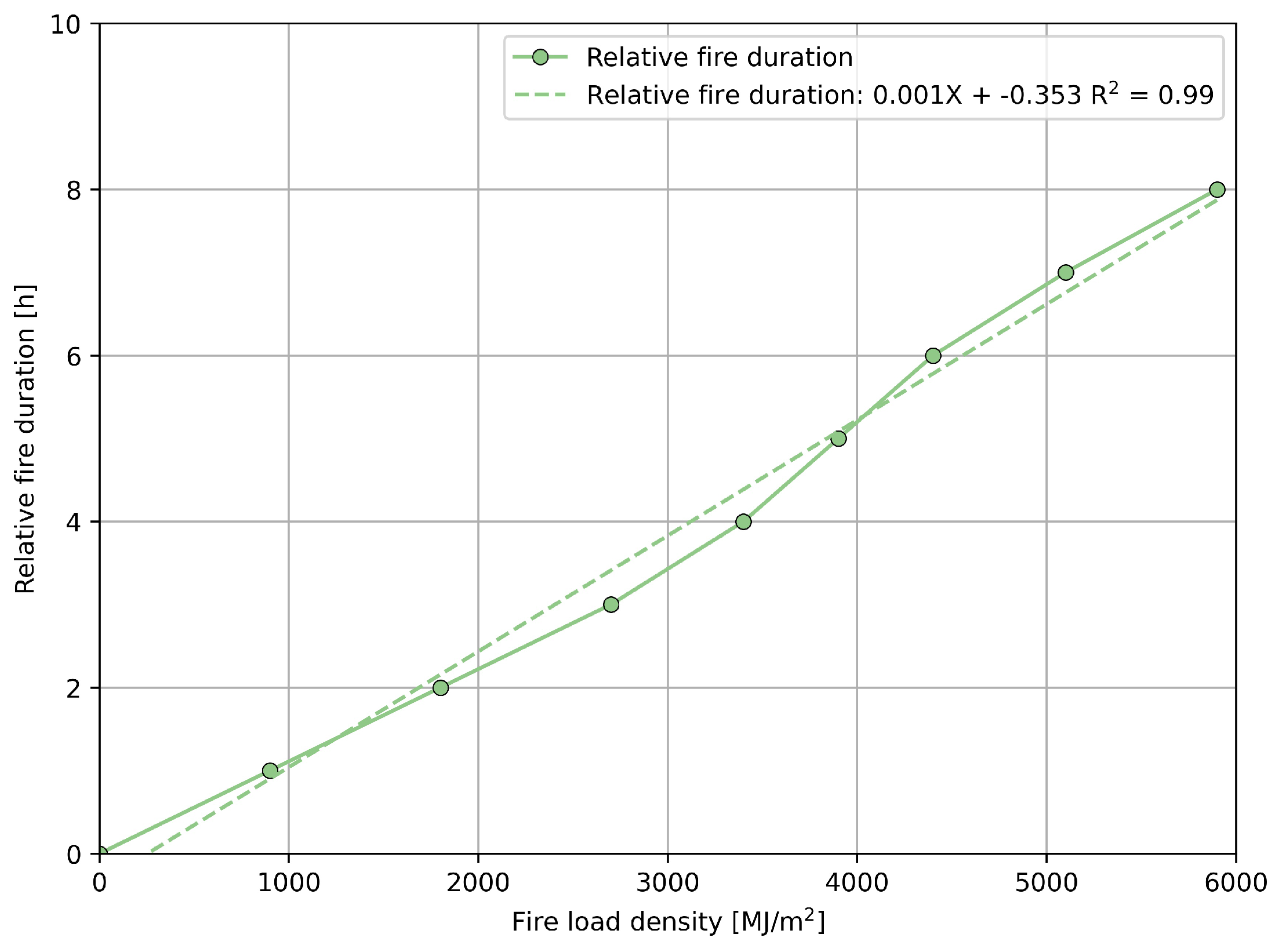
  49. PN-B-02852:2001; Ochrona Przeciwpożarowa Budynków—Obliczanie Gęstości Obciążenia Ogniowego Oraz Wyznaczanie Względnego Czasu Trwania Pożaru. Polski Komitet Normalizacyjny: Warsaw, Poland, 2001.
Figure 1. The AMIGA fire suppression system is designed to protect: (a) the belt conveyor drive, and (b) the belt conveyor return end.
Energies 16 06077 g001
Figure 2. The placement of mist nozzles in the space between the loading point of the conveyor and the return station of the receiving conveyor.
Energies 16 06077 g002
Figure 3. The arrangement of the analyzed nozzles of the spraying pack above the conveyor drive.
Energies 16 06077 g003
Figure 4. Parameters of coal combustion depending on the fire’s power.
Energies 16 06077 g004
Figure 5. Relative duration of fire depending on fire load density [29].
Energies 16 06077 g005
Figure 6. The test rig consists of a drive model equipped with an automatically activated mist-spraying system with a pneumatic detection line for protecting the drive and transferring areas of belt conveyors.
Energies 16 06077 g006
Figure 7. Locations of placing the tray with flammable material: (a) under the drive model, and (b) on the drive model.
Energies 16 06077 g007
Figure 8. A prism of combustible material ignited by a burner.
Energies 16 06077 g008
Figure 9. The results of extinguishing the combustible material using mist cone nozzles: (a) pressure of extinguishing water, (b) flow rate of extinguishing water, (c) flame extinguishing time, and (d) temperature of the prism after 60 s from flame extinguishment.
Energies 16 06077 g009
Figure 10. Successful attempt to extinguish the burning material bed located beneath the conveyor belt drive model using mist nozzles: (a) burning bed before initiating the fire suppression, and (b) burning bed at the system startup and end after fire extinguishment.
Energies 16 06077 g010
Figure 11. Results of extinguishing the combustible material using spiral nozzles: (a) pressure of extinguishing water, (b) flow rate of extinguishing water, (c) flame extinguishing time, and (d) temperature of the prism after 60 s from the end of flame extinguishment.
Energies 16 06077 g011
Figure 12. Successful attempt to extinguish the burning material bed located on the upper belt of the conveyor drive model using spraying nozzles: (a) burning the bed before starting the fire extinguishing, (b) burning bed immediately after startup of fire extinguishing system, and (c) burning bed immediately after successful fire extinguishing.
Energies 16 06077 g012
Figure 13. The averaged fire extinguishing times by the mist installation and sprinkler system, depending on the water supply pressure.
Energies 16 06077 g013
Figure 14. The energy required to achieve an effective spraying stream for a single sprinkler and mist nozzle, depending on the water supply pressure.
Energies 16 06077 g014
Figure 15. Temperature of the extinguished material in relation to the amount of water used for fire extinguishing and cooling for 60 s.
Energies 16 06077 g015
Figure 16. Extinguishing time in relation to the amount of water used for fire suppression.
Energies 16 06077 g016
Figure 17. Presentation of fire suppression initiated simultaneously on the upper belt (protected by the water spraying system) and inside the drive station (protected by the water mist system): (a) before activating the AMIGA fire suppression system, and (b) after the activation of the AMIGA fire suppression system.
Energies 16 06077 g017
Table 1. The total flow rate of the applied mist nozzles in the conveyor drive.
Type of Mist NozzleNumber of NozzlesFlow Rate at 2.5 bar Pressure [dm3/min]Total [dm3/min]
Cone43.614.4
Flat51.47.0
Total [dm3/min]21.4
Table 2. The results of water energy consumption required to achieve different combinations of spray streams.
Type of InstallationWater Pressure p W [MPa]Water Flow Rate V ˙ W [dm3/min]Extinguishing Time [s]Water Energy E w [kJ]Water Energy Per 1 s E w / s [kJ]Energy Used for Extinguishing E [kJ]Energy Per Spraying Nozzle E d [kJ]
Mist0.42415.69.600.162.500.28
0.533.5610.816.780.283.020.34
148.885.648.880.814.560.51
1.4862.73.492.801.555.260.58
Spiral0.39440.269.7515.860.262.580.64
0.51242.28.621.610.363.100.77
0.93647.546.644.500.744.891.22
1.5550.724.678.621.316.031.51
Disclaimer/Publisher’s Note: The statements, opinions and data contained in all publications are solely those of the individual author(s) and contributor(s) and not of MDPI and/or the editor(s). MDPI and/or the editor(s) disclaim responsibility for any injury to people or property resulting from any ideas, methods, instructions or products referred to in the content.

