Article

Platinum–Nickel Electrocatalysts for a Proton-Exchange Membrane Fuel Cell Cathode: Their Synthesis, Acid Treatment, Microstructure and Electrochemical Behavior

1
Faculty of Chemistry, Southern Federal University, 7 Zorge St., Rostov-on-Don 344090, Russia
2
Research Institute of Physical Organic Chemistry, Southern Federal University, 194/2 Stachki St., Rostov-on-Don 344090, Russia
*
Author to whom correspondence should be addressed.
Energies 2023, 16(16), 6078; https://doi.org/10.3390/en16166078
Submission received: 2 July 2023 / Revised: 14 August 2023 / Accepted: 18 August 2023 / Published: 20 August 2023
(This article belongs to the Section D3: Nanoenergy)

Abstract

:
Within this research, we studied the structural–morphological and electrochemical characteristics of the PtNi/C catalysts synthesized via the two-stage sequential reduction of precursors. We also carried out a comparative study of the obtained bimetallic catalysts and their commercial Pt/C analog. The use of triethylamine as a surfactant as well as the acid treatment as an additional synthesis stage, were shown to have a positive effect on the functional parameters of the bimetallic electrocatalysts. The resulting PtNi/C electrocatalyst demonstrates a mass activity value of 389 A gPt−1, which is 1.6 times higher than this parameter for a commercial analog.

1. Introduction

Currently, increasing attention is being given to the development of hydrogen energy due to the fact that devices running on hydrogen fuel are characterized by high-performance energy conversion and produce no harmful emissions [1]. One of the most promising methods to replace internal combustion engines as vehicle energy sources is the use of fuel cells with a proton-exchange membrane (PEMFCs) [2,3]. These devices are based on the principal cell reactions proceeding inside, i.e., hydrogen oxidation at the anode and oxygen reduction at the cathode. Electrocatalysts are used in both the anode and cathode regions of a fuel cell (FC). Nanoparticles (NPs) deposited on the carbon support are most commonly employed as those catalysts [4]. The oxygen electroreduction reaction (ORR) is characterized by its multistage nature and the simultaneous formation of intermediates. It requires high overvoltage and, thus, greater platinum loading in the catalytic layer [5,6,7]. Today, it is known that electrocatalysts based on bimetallic NPs may be characterized by higher activity in terms of ORR compared to pure platinum [8,9,10,11,12]. Alloying with d-metals has a positive effect on the adsorption of O2 on the catalyst surface, with this reaction being facilitated due to a reduced interatomic distance in the platinum crystal lattice and changing the energy of free d-orbitals [13]. This influence is called a “ligand effect”, due to which the activity in the ORR increases.
Nørskov J.K. et al. [14] describe a volcanic dependence between the ORR activity of some platinum alloys and oxygen adsorption energy, implying that one of those alloying metals increasing the ORR mass activity of the catalysts is nickel.
The studies specified in [15,16,17,18,19] point out that platinum–nickel materials are not characterized by high values in terms of the electrochemically active surface area (ECSA) compared to a commercial Pt/C analog, although their performance is notably higher in terms of ORR.
The problem of synthesizing PtNi catalysts consists of nickel being subject to oxidation even at temperatures as low as 23 °C. Therefore, the synthesis should be carried out in non-aqueous anoxic media using various surfactants and organometallic precursors in an inert or reducing atmosphere [20]. Gong W. et al. [17] report the synthesis of a material with an activity 3.4 times higher than that of the Pt/C catalyst. However, this catalyst has a complex morphology. The researchers managed to obtain the branched nanostructures from an organic nickel precursor (Ni(acac)2). To achieve those structures, organic surfactants were used, which usually heavily contaminate the catalyst. The studies by Yao N. et al. [18] describe synthesizing a catalyst with an ORR activity 3.6 times higher than that of Pt/C. Nevertheless, to synthesize that material, the researchers also used organic platinum and nickel precursors (Pt(acac)2, Ni(acac)2), with DMF being used as a solvent. The operating temperature of the synthesis ranged from 140 to 900 °C, which made it unprofitable in terms of large-scale production. During the synthesis, an additional polymerization reaction of the finished catalyst in aniline was carried out. This technique is not only difficult to reproduce, but it also requires the additional use of expensive equipment, energy costs and additional cleaning steps.
As can be seen, most syntheses use organic precursors of nickel and platinum, complex equipment, and elevated temperatures, increasing the cost of the synthesis of these catalysts. The use of these reagents, as well as the special conditions of the processes proceeding during the synthesis, complicate the production of PtNi/C materials in industrial quantities, hindering their use in FCs. Additionally, most syntheses use organic surfactants. For example, the study undertaken by Leteba G.M. et al. [19] reports a catalyst that took 3 weeks to synthesize. As a surfactant, they used a mixture of three organic substances, such as oleylamine, OLEA or TOA, as well as hydrophobic surfactants, which usually heavily contaminate the catalyst, complicating the process of its purification. The latter requires using large amounts of organic solvents (chloroform), applying additional expensive equipment and increasing the number of cleaning steps, which also hampers the production of these materials. Wang J. et al. [15] describe the synthesis of a catalyst, the activity of which is 1.6 times higher than that of the commercial sample. However, they also used organic metal precursors (Pt(acac)2, Ni(acac)2), with benzoic acid acting as a surfactant, which contaminates the catalyst as well.
The activity of the electrocatalyst in relation to ORR is known to be determined by the NPs’ architecture, composition and size, as well as their distribution over the surface of the support [21,22,23]. The PtM NPs’ main structure types, described in the literature and used in the synthesis of electrocatalysts, include solid solutions (alloys and intermetallide) [24,25] and core–shell, with the core consisting of an alloying metal or the core being the PtM alloy [26,27]. During liquid-phase synthesis with the homogeneous and heterogeneous nucleation of NPs, it is impossible to obtain bimetallic particles with ideal structures. A partially alloying metal is deposited on the surface of the platinum or carbon support [28]. This metal may have a negative impact not only on the catalyst’s functional characteristics but also on the operation of the entire FC. It does not participate in the ORR and blocks the available sections of platinum, thus decreasing the activity of these “contaminated” catalysts. During the operation of these catalysts, the alloying component is selectively dissolved from the surface of the catalyst’s NPs due to its decreased thermodynamic stability compared to Pt [21], which may be conducive to the poisoning of the proton-conducting membrane in the FC [29], and thus, the destruction of NPs.
Synthesizing NPs with an alloy structure is the simplest method and is carried out in a single stage. The multistage methods used to synthesize NPs in the form of nanotubes or with a core–shell structure are more common among different publications [16,17,19,27,30]. Due to the promoting effect of cores consisting of a less noble metal, the Pt shell exhibits increased electrochemical characteristics in the cell reactions compared to pure platinum. The prevailing arrangement of platinum atoms on the surface of NPs not only increases the electrocatalyst’s performance but also reduces the content of the costly metal required. The advantage of this type of NP is also the ability to prevent the dissolution of the base metal due to the protective properties of a more thermodynamically stable shell. Despite the stability of the core–shell materials, they are also prone to the selective dissolution of the alloying component during their surface standardization and operation [31]. Therefore, an acid post-treatment of the finished catalyst is used for PtNi/C materials, which can enhance the electrochemical properties of the catalysts and stabilize their composition, preventing the further dissolution of the base metal [32,33,34]. Thus, all studies regarding bimetallic catalysts require an acid treatment as a necessary synthesis stage that allows for obtaining reliable data on the functional characteristics of these catalysts.
The main idea of this study is to synthesize high-performance bimetallic catalysts with a reduced platinum content via a single-volume method that might be simple and profitable for commercial production.
The hypothesis of this study implies that the use of simple reagents as well as resource-efficient synthesis would make it possible to obtain more active catalysts.

2. Materials and Methods

2.1. Materials

Dihydronium hexachloroplatinate(2−) (H2PtCl6·6H2O, hydrogen hexachloroplatinate(IV); extra pure grade, Aurat, Russia, platinum mass fraction 37.6%), nickel(II) chloride (NiCl2·6H2O, nickel chloride, 6-aqueous; extra-pure grade, JSC Vekton, Saint-Petersburg, Russia), N,N-Diethylethanamine ((C2H5)3N, triethylamine; extra-pure grade, JSC Vekton, Saint-Petersburg, Russia), ethanol (C2H5OH; extra-pure grade, Sigma-Aldrich, St. Louis, MO, USA), sodium tetrahydridoborate(1−) (NaBH4, sodium borohydride; extra-pure grade, JSC Vekton, Saint-Petersburg, Russia), propan-2-ol ((CH3)2CHOH, isopropanol; pure for analysis, EKOS-1, Moscow, Russia), bidistilled water, carbon support Vulcan XC-72 (Cabot Corporation, Boston, MA, USA), chloric(VII) acid (HClO4, perchloric acid; extra-pure grade, Sigma-Aldrich, St. Louis, MO, USA), and perfluorinated resin (Nafion DE1020, 10% aqueous dispersions, DuPont, Wilmington, DE, USA) were obtained.
To compare the functional characteristics of the obtained materials, we used the commercial Pt/C electrocatalyst HiSPEC 3000 (JM20) (Johnson Matthey, 20% Pt loading).

2.2. Synthesis of the PtNi/C Catalyst with a Core–Shell NP Structure

The nickel-based catalysts were synthesized via the liquid-phase step-by-step borohydride method in an inert atmosphere with a theoretical platinum loading of 20%. During the entire synthesis process, the reaction mixture was purged with argon. The temperature did not exceed 70 °C. Vulcan XC-72 was used as the carbon support. The interval between stages amounted to 30 min.
In the first stage, the pre-calculated amount of nickel chloride was dispersed from 0.2 g of the carbon support in 30 mL of ethanol using an ultrasonic homogenizer. After that, the required amount of triethylamine (TEA) was added to the suspension, adjusting the volume of the reaction mixture to 100 mL with ethanol. Then, the suspension was placed onto a magnetic stirrer and heated. The reaction mixture was purged with argon and heated. After reaching the required temperature, a three-fold excess of the reducing agent NaBH4 was added to the mixture.
In the second stage, the pre-calculated amount of H2[PtCl6]∙6H2O and the reducing agent in its three-fold excess were added.
In the third stage, another portion of a three-fold excess of sodium borohydride required to reduce Pt was added to the mixture and kept for 30 min.
After all these stages, the mixture was cooled. After the mixture was cooled to room temperature, the resulting catalyst was filtered and rinsed alternately with ethanol and bidistilled water using a Büchner funnel. At the end of rinsing, the material was placed into the desiccator and left to dry for several days. The sample obtained without using TEA is hereinafter referred to as S1. The samples with TEA are hereinafter referred to as S2.

2.3. Preparation of the De-Alloyed Catalysts

To carry out the acid treatment, 50 mL of 0.1 M HNO3 was added to weighed amounts of each PtNi/C catalyst (0.1 g). The mixture was placed onto a magnetic stirrer and stirred for 3 h. The treatment was carried out without heating.
After the treatment, the electrocatalyst was rinsed with bidistilled water and filtered using a Büchner funnel. At the end of rinsing, the sample was placed into the desiccator and dried for several days. The resulting samples are marked as S1–A and S2–A, respectively.

2.4. Methods to Study the Catalysts’ Composition and Structure

The metals’ mass fraction in the electrocatalysts was determined via gravimetry from the mass of the unburned residue when heated to 800 °C, taking into account the oxidation of nickel to nickel(II) oxide.
X-ray fluorescence (TXRF) analysis using a spectrometer with total external reflection of X-ray radiation RFS-001 (Research Institute of Physics, Southern Federal University, Rostov-on-Don) was used to determine the ratio of metals in the samples. The registration and processing of X-ray fluorescence spectra were carried out using UniveRS software (Southern Federal University, Rostov-on-Don). The obtained X-ray fluorescence spectra were processed using UniveRS software (Southern Federal University, Rostov-on-Don), the resulting accuracy being ±0.1.
The X-ray patterns were recorded using the ARL X`TRA powder diffractometer (Thermo Scientific, Switzerland) with Bragg–Brentano geometry (θ–θ) and CuKα radiation (λ = 0.15405618 nm). The measurements were carried out at room temperature. The samples were thoroughly stirred and placed into a 1.5 mm deep cuvette or onto a background-free substrate. The X-ray patterns for the studied samples were recorded in the range of angles of 15° ≤ 2θ ≤ 55° via step-by-step scanning with a detector movement step of 0.04° and an exposure time at each point of 2 s. The average crystallite size of the metallic phase was determined using the Scherrer equation for the most intense peak (111), as described in [35].
The samples’ size, microstructure, and elemental composition were studied via transmission electron microscopy (TEM) and energy-dispersive X-ray spectrometry (EDX). The micrographs were obtained using the JEM-2100 microscope (JEOL, Tokyo, Japan) at a voltage of 200 kV and a resolution of 0.2 nm. To carry out the measurements, 0.5 mg of the catalyst was placed in 1 mL of isopropanol and dispersed with ultrasound, after which the resulting suspension was applied to the copper grid coated with a layer of amorphous carbon and dried in air at room temperature for 20 min.

2.5. Electrochemical Methods

The measurements were carried out in a standard three-electrode cell at the temperature of 25 °C using the Pine AFCBP1 bipotentiostat (Pine Research Instrumentation, Durham, NC, USA). The electrolyte used was a 0.1 M HClO4 solution. A saturated silver chloride electrode was used as the reference electrode. The values of the potentials were considered in this study relative to the reversible hydrogen electrode (RHE).
To obtain the suspension of the metal–carbon material (catalytic “inks”), 1600 µL of deionized water, 50 µL of Nafion® 0.1% aqueous emulsion and 800 µL of isopropyl alcohol were added to the weighed amounts of each sample (0.0060 g). Then, the suspension was dispersed with ultrasound for 15 min. With continuous stirring, a 5 µL aliquot of the inks was selected using a pipette tip and applied to the end face of the polished and degreased glass–carbon electrode with an area of 0.196 cm2, recording an exact weight of the resulting drop. The working electrode was dried in air at a rotation speed of 700 rpm.
Before measuring the ECSA of the catalyst, the electrolyte was saturated with argon for 30 min. Next, the electrode was standardized by setting 100 potential sweep cycles in the range from 0.04 to 1.00 V at a rate of 200 mV s1 [36]. Then, 2 cyclic voltammograms (CVs) at the potential sweep rate of 20 mV s1 were recorded on the stationary electrode. The ECSA was calculated for the second CV by the charge amount consumed for the electrochemical adsorption and desorption of atomic hydrogen, taking into account the contribution of the double-electric layer currents, as described in [37].
To assess the ORR activity of the catalysts, the electrolyte was saturated with oxygen for 1 h, after which a series of voltammograms were measured in the range from 0.1 to 1.2 V with a linear potential sweep at a rate of 20 mV s1 and at electrode rotation speeds of 400, 900, 1600 and 2500 rpm. To account for the contribution of the ohmic potential drop and the processes unrelated to ORR, the resulting voltammograms were normalized according to conventional methods [38]. For this purpose, the potential of the studied electrode was refined by the formula: E = Eset − IR, where Eset is the set value of the potential and IR is the ohmic potential drop equal to the product of the current strength by the resistance of the solution layer between the reference electrode and the electrode studied, which, in this case, amounted to 23 ohms. This resistance value correlates well with the literature data [39]. The contribution of the processes proceeding on the electrode in a deoxygenated solution (Ar atmosphere) was taken into account by subtracting from the voltammogram an equivalent curve recorded on the same electrode during the measurements in an Ar atmosphere and at an electrode rotation speed of 1600 rpm: I(O2) − I(Ar). The ORR activity of the catalysts (kinetic current) was determined via normalized voltammograms, taking into account the mass transfer contribution and subject to the measurements performed on the rotating disk electrode (RDE) [38]. The kinetic current was calculated using the Koutetsky–Levich equation: 1/j = 1/jk + 1/jd, where j is the experimentally measured current, jd is the diffusion current and jk is the kinetic current. The kinetic currents were calculated at a potential of 0.9 V. All the potentials used in this study were considered with regard to the RHE.
The start/stop protocol has been applied as an accelerated stress testing method to assess the durability of electrocatalysts. The protocol consists of repeated imposition of 3 s square-wave potential pulses of 0.4 and 1.0 V for 10,000 cycles. Cycling was carried out in an electrolyte of 0.1 M HClO4 saturated with oxygen [40]. The durability of the electrocatalysts was estimated from the change in the values of the ECSA and the ORR mass activity at 1600 rpm.

3. Results and Discussion

The synthesis approach proposed in this study implies that the synthesis itself requires no complex or expensive equipment. The entire synthesis is carried out using the single-volume method at a low temperature, which makes it quite resource-saving. Inorganic substances are used herein as precursors, which not only reduces the cost of production but also minimizes the presence of difficult-to-remove impurities. Moreover, the synthesis takes little time—no more than 3 h. Triethylamine is selected as a surfactant based on the data presented in [41,42,43]. During the multistage synthesis of the materials based on bimetallic particles, the formation of NPs of various compositions and structures is possible, i.e., individual Pt NPs, individual nickel NPs coated with nickel oxide and PtNi with alloy and core–shell structures. The surface of all bimetallic NPs may also exhibit a portion of nickel atoms that are not included in the composition. During the operation of an FC, a base metal may be dissolved from the catalyst’s surface, which leads to the poisoning of the proton-exchange membrane. Thus, it is necessary to obtain “ideal” NPs, on the surface of which there are no d-metal atoms “unshielded” by the platinum shell (Figure 1). During the liquid-phase synthesis, it is impossible to obtain NPs with an ideal structure. Therefore, an essential stage of the synthesis is the acid treatment, which additionally cleans the catalyst’s surface of nickel, which is not included in the solid solution composition (Figure 1).
The X-ray diffraction patterns of the initial and acid-treated catalysts are shown in Figure 2. The X-ray diffraction patterns of all the samples demonstrate the platinum phases with a face-centered cubic (FCC) lattice and the carbon phases (Figure 2). They also exhibit a shift in the positions of the Pt 111 and 200 peaks compared to the standard reflection values. The most intense peaks in the X-ray patterns are located between the corresponding positions of Pt and Ni, which confirms the entry of nickel into the crystalline phase and the formation of the solid solution (Figure 2).
The average crystallite diameters have been calculated using the Scherrer equation. For the samples synthesized with the introduction of TEA, the average crystallite diameter is greater than that for the pure PtNi/C material (Table 1). The fraction of Ni included in the alloy structure has been calculated according to Vegard’s law (Table 1). The calculated data also confirm that samples containing bimetallic NPs were obtained.
For the samples after the acid treatment (S1–A, S2–A, S3–A), according to Vegard’s law, the composition of bimetallic NPs changed insignificantly compared to the initial samples S1, S2, and S3 (Table 1).
The average crystallite diameter calculated via the Scherrer equation for the obtained PtNi/C materials ranges from 4.0 to 5.9 nm (Table 1). For the acid-treated samples, this value has slightly increased by 0.6 and 0.3 nm (for the samples S1–A and S2–A, respectively) (Table 1). To a lesser extent, an increase in the average diameters is observed for the materials synthesized in the presence of TEA. Unfortunately, X-ray powder diffraction (XRD) fails to provide any information on the nature of the metals’ distribution in two-component NPs. Moreover, the calculation of the crystallite size according to the Scherrer formula, undertaken using the half-width of the characteristic reflection in the X-ray diffraction pattern, may provide incorrect results for NPs with a core–shell architecture, which is due to the complexity in separating the phase reflections based on platinum and nickel d-metal [44,45,46].
The TEM micrographs of the platinum-based materials demonstrate the presence of nanoscale metallic particles of spherical shape distributed over the carbon support (Figure 3). The analysis of the micrographs for the platinum–nickel catalysts has shown that the material synthesized without introducing TEA exhibits a more uniform NP distribution over the carbon support (Figure 3a–c). Sample S2 contains large NP agglomerates that resemble a moss-like structure (Figure 3e–g). Previous studies [33,47] show that PtNi is characterized by the formation of NP agglomerates during liquid-phase synthesis. According to the results derived from TEM micrographs, it cannot be concluded that TEA is the surfactant to prevent the agglomeration of NPs in bimetallic systems, as shown during the preparation of Ag/Au and Pt NPs [41,43].
The average size of the NPs determined using the TEM results does not coincide with the average crystallite size (XRD) of the PtNi/C catalysts. This phenomenon is due to various reasons, including the error in the calculations of PtNi crystallites, the existence of bimetallic NPs with different architectures, and the presence of a transitional amorphized layer at the interphase of the NPs with a core–shell architecture. Moreover, individual NPs may consist of several crystallites [48].
In addition, the S1 and S2 samples exhibit NP agglomeration, which is observed to a greater extent for the S2 material. The catalyst synthesized without the introduction of TEA has the smallest average diameter of NPs (5.7 nm), which is almost two times less than that of S2. The S2 sample and its acid-treated analog are characterized to a greater extent by the presence of NP agglomerates of 12–20 nm in size than the S1 and S1–A samples (Figure 3c,d,g,h).
The EDX mapping results for separate sections of the catalysts’ surface confirm the bimetallic composition of individual NPs (Figure 4). The EDX maps of the initial materials and their acid-treated analogs show that the nickel localization sites coincide with those for platinum, which also confirms the presence of the NPs containing both platinum and nickel on the surface of the carbon support (Figure 4).
Additional data on the NPs’ composition and structure have been obtained via the EDX scanning of individual NPs (Figure 4e–h). The platinum and nickel peaks in both the initial and acid-treated samples are in the same positions, which is one of the proofs of the formation of the Pt–Ni alloy. For the S1 sample, the nickel content in the scanned area is higher than the platinum content, which confirms a nonuniform local distribution of the d-metal over the surface of NPs for this sample (Figure 4e). After the acid treatment, the catalysts exhibit a sharp decrease in nickel content in the NPs, which is associated with the leaching of the alloying metal located on the surface of the Pt shell. The S2, S1–A and S2–A samples exhibit the presence of NPs with Pt shells (Figure 4f–h). The composition of the metal component determined via EDX for the S1 material is PtNi3.9, while after the acid treatment, in the S1–A sample, it has changed to Pt3.8Ni. For the S2 sample, the ratio of metals is PtNi1.0, this being Pt3.6Ni for S2–A.
Additionally, the ratio of metals has been evaluated using TXRF. The composition of the de-alloyed catalysts is Pt1.3Ni and Pt1.6Ni for S1–A and S2–A, respectively. The difference in the composition, as determined via TXRF and EDX, is related to the specificity of the methods. The EDX analysis is performed at a local area of the surface, while TXRF shows an average result of studying the metal components in the sample.
The key stage in studying the electrochemical behavior of the electrocatalysts is the preparation of catalytic inks and the application of a drop of those inks to the end face of the RDE to form a thin catalytic layer [39,49,50]. To obtain a high-quality catalytic layer of the PtNi/C catalyst, the ink preparation technique, which is commonly used in various publications regarding Pt/C materials [39,51,52], has proved to be unsuitable. Figure 5 demonstrates the appearance of the catalytic layer at the end face of the glass–carbon RDE obtained by using inks of various compositions. Figure 5 also shows the changes observed in the catalytic layer quality depending on the changing ratio of water and isopropyl alcohol in the composition. It can be seen that the catalytic layer either fails to cover the surface of the electrode (Figure 5a,b) or forms large clusters in the middle of the RDE (a), as well as forms a so-called coffee ring, as described in [52,53]. The most acceptable type of catalytic layer is shown in Figure 5d, i.e., a uniformly coated RDE. The selected composition of the catalytic inks is described in the Experimental Section.
The CVs of the activation stage for the initial and acid-treated materials as well as their commercial analog (Figure 6), demonstrate an increase in the currents in the hydrogen and oxygen regions followed by their stabilization. The above is connected with the catalysts’ surface purification and development.
After the activation stage, for all samples, two cycles of the current–voltage curves have been recorded, and the ECSA (Table 2) has been calculated using hydrogen adsorption/desorption (Figure 6f,i). Similar studies have been conducted for the commercial catalyst JM20. It is worth noting that lower currents in the hydrogen region and a decreased ECSA value for the PtNi/C materials compared to Pt/C are associated with the size of NPs (more than 4 nm). For the acid-treated samples, the ECSA increases by 3–5 m2 gPt−1 (Table 2).
The ORR activity of the catalysts has been assessed in the potentiodynamic mode (Figure 6g,j). According to the results of studying the dependence in the Koutetsky–Levich coordinates (Figure 6h,k), it can be pointed out that the S2 sample synthesized in the presence of TEA exhibits the highest ORR activity among the initial catalysts (Table 2). After the acid treatment, all the bimetallic catalysts become more active compared to the initial samples and the commercial JM20. The S2–A sample exhibits the highest mass activity among all the materials studied (Table 2).
The ORR mass activity of the catalysts grows in the order: S1 < JM20 << S2 ≈ S1–A < S2–A. It can be seen that the bimetallic catalyst synthesized with the introduction of triethylamine as well as its acid-treated analogs, S1–A and S2–A, exhibits the highest activity. This dependence shows that the acid treatment has a positive effect on the functional characteristics of the bimetallic catalysts. The treatment allows for the removal of the base metal from the catalyst’s surface and, at the same time, increases the material’s functional characteristics, which makes it a necessary stage in terms of the synthesis of bimetallic catalysts.
The ORR impedance of the S2–A material has been estimated in terms of RDE. Figure S4 shows the impedance hodograph in Nyquist coordinates. The impedance hodographs have been calculated according to the equivalent circuit shown in Figure S4 since there are no areas characterizing diffusion problems.
Figure 7 shows histograms of the electrocatalysts’ functional characteristics after stress testing. Despite the lower active surface area compared to the commercial Pt/C, the bimetallic catalyst S2–A is characterized by a two times higher mass activity in ORR after stress testing.
Additionally, we synthesized the S3 sample using triethylamine with its double excess and carried out the acid treatment of the resulting S3–A material. The results of this study are provided in the Supplementary Materials.

4. Conclusions

In terms of this study, we have synthesized a series of the PtNi/C electrocatalysts without triethylamine and in its presence. The materials are characterized by an average crystallite size of 4–6 nm. We have assessed the composition and structure of the bimetallic catalysts using the corresponding methods, and the results of this assessment confirm the entry of Ni into the crystalline phase as well as the formation of the NPs with a solid solution structure. The TEM micrographs demonstrate visible differences in the morphology of the materials, which is due to the influence of triethylamine introduced during the synthesis. In the presence of triethylamine, we may observe larger bimetallic NPs as well as the formation of NP aggregates.
The obtained catalysts exhibit ECSA values of 20–30 m2 gPt−1. After the acid treatment, for all the PtNi/C catalysts, we may observe an increase in these values. The S1–A sample exhibited an increase in ECSA to the greatest extent—by 33%. This may be due to an additional step of cleaning the catalyst’s surface of triethylamine, the selective dissolution of the alloying metal or the rearrangement of the surface of the bimetallic NPs.
The PtNi/C electrocatalyst obtained in the presence of TEA exhibits an increased residual activity after stress testing, this value exceeding an equivalent parameter for the commercial analog by 1.6 times.
Using TEA allows a stable and active catalyst due to the presence of the NPs that are located in the form of islets resembling moss. The absence of small NPs makes the catalyst more stable during stress testing, whereas the presence of defects inside a NP as well as the ligand effect, ensure an increased activity of these NPs in the ORR.
The results obtained in this study reveal a positive effect of alloying the platinum-based catalysts with nickel on the ORR activity of these materials, which makes platinum–nickel systems of interest in terms of further research objects regarding the development of electrocatalysts in the MEA. It has also been established that the introduction of triethylamine and acid treatment may enhance the characteristics of the above systems. The use of triethylamine as a surfactant requires no complex equipment, additional conditions, or steps of cleaning the surface of the catalyst for its further application.

Supplementary Materials

The following supporting information can be downloaded at: https://www.mdpi.com/article/10.3390/en16166078/s1, Figure S1: X-ray diffraction patterns of the obtained bimetallic catalysts. Positions of the standard reflections for Pt, Ni and NiO are indicated; Table S1: Composition and structural parameter of obtained PtNi/C catalysts; Figure S2: CVs of the activation stage for the PtNi/C catalysts. In total, 100 cycles in the potential range of 0.04–1.00 V: S3 (a), S3–A (b). Potential sweep rate is 200 mV/s. Atmosphere of Ar, 0.1 M HClO4. Figure S3: Cyclic voltammograms at the potential sweep rate of 20 mV/s (a) for the samples activated in the potential range of 0.04–1.00 V and in an Ar atmosphere. Linear sweep voltammograms of the oxygen electroreduction in the studied catalysts at the RDE rotation speed of 1600 rpm, at the potential sweep rate of 20 mV s−1 and in an O2 atmosphere (b). 0.1 M HClO4. Dependence 1/j of ω−1/2 at the potential of 0.90 V (c). Figure S4: Impedance hodograph and equivalent circuit of electrocatalyst S2-A for the oxygen reduction reaction on RDE (1600 rpm) at 0.9 V (vs. RHE). 0.1 M HClO4.

Author Contributions

Conceptualization, A.A. and E.K.; methodology, E.K. and A.P.; validation, E.K., A.P. and A.A.; investigation, E.K. and I.P.; writing—original draft preparation, E.K.; writing—review and editing, A.P. and A.A.; visualization, A.P.; supervision, A.A. All authors have read and agreed to the published version of the manuscript.

Funding

This research was financially supported by the Ministry of Science and Higher Education of the Russian Federation (State Assignment in the Field of Scientific Activity No. FENW-2023-0016).

Data Availability Statement

All data generated or analysed during this study are included in this published article and its supplementary information files.

Acknowledgments

The authors express their deep appreciation to the Shared Use Center “High-Resolution Transmission Electron Microscopy” (SFedU). The authors are grateful to Maltsev, A.V. for the support in translation and editing processes and the assistance in communication with the editorial board. The authors are also grateful to Nikulin, A. Yu. for assistance in the XRD pattern registration.

Conflicts of Interest

The authors declare no conflict of interest.

Abbreviations

NPsNanoparticles
FCFuel cell
PEMFCsProton-exchange membrane fuel cells
ORROxygen reduction reaction
TEATriethylamine, N,N-Diethylethanamine
OLEAOleic acid, (9Z)-Octadec-9-enoic acid
TOATrioctylamine, N,N-Di(octyl)octan-1-amine
DMFDimethylformamide, N,N-Dimethylformamide
XRDX-ray powder diffraction
TEMTransmission electron microscopy
EDXEnergy-dispersive X-ray spectrometry
ECSAElectrochemically active surface area
CVCyclic voltammetry
LSVLinear sweep voltammetry
STEMScanning transmission electron microscopy
RDERotating disk electrode
RHEReversible hydrogen electrode
MEAMembrane electrode assembly
FCCFace-centered cubic

References

  1. Olabi, A.G.; Sayed, E.T. Developments in Hydrogen Fuel Cells. Energies 2023, 16, 2431. [Google Scholar] [CrossRef]
  2. Pourrahmani, H.; Yavarinasab, A.; Siavashi, M.; Matian, M.; Van herle, J. Progress in the Proton Exchange Membrane Fuel Cells (PEMFCs) Water/Thermal Management: From Theory to the Current Challenges and Real-Time Fault Diagnosis Methods. Energy Rev. 2022, 1, 100002. [Google Scholar] [CrossRef]
  3. Pedicini, R.; Romagnoli, M.; Santangelo, P.E. A Critical Review of Polymer Electrolyte Membrane Fuel Cell Systems for Automotive Applications: Components, Materials, and Comparative Assessment. Energies 2023, 16, 3111. [Google Scholar] [CrossRef]
  4. Kodama, K.; Nagai, T.; Kuwaki, A.; Jinnouchi, R.; Morimoto, Y. Challenges in Applying Highly Active Pt-Based Nanostructured Catalysts for Oxygen Reduction Reactions to Fuel Cell Vehicles. Nat. Nanotechnol. 2021, 16, 140–147. [Google Scholar] [CrossRef] [PubMed]
  5. Fan, J.; Chen, M.; Zhao, Z.; Zhang, Z.; Ye, S.; Xu, S.; Wang, H.; Li, H. Bridging the Gap between Highly Active Oxygen Reduction Reaction Catalysts and Effective Catalyst Layers for Proton Exchange Membrane Fuel Cells. Nat. Energy 2021, 6, 475–486. [Google Scholar] [CrossRef]
  6. Si, F.; Zhang, Y.; Yan, L.; Zhu, J.; Xiao, M.; Liu, C.; Xing, W.; Zhang, J. Electrochemical Oxygen Reduction Reaction. In Rotating Electrode Methods and Oxygen Reduction Electrocatalysts; Elsevier: Amsterdam, The Netherlands, 2014; pp. 133–170. [Google Scholar] [CrossRef]
  7. Gómez-Marín, A.M.; Ticianelli, E.A. A Reviewed Vision of the Oxygen Reduction Reaction Mechanism on Pt-Based Catalysts. Curr. Opin. Electrochem. 2018, 9, 129–136. [Google Scholar] [CrossRef]
  8. Escudero-Escribano, M.; Jensen, K.D.; Jensen, A.W. Recent Advances in Bimetallic Electrocatalysts for Oxygen Reduction: Design Principles, Structure-Function Relations and Active Phase Elucidation. Curr. Opin. Electrochem. 2018, 8, 135–146. [Google Scholar] [CrossRef]
  9. Strasser, P.; Koh, S.; Anniyev, T.; Greeley, J.; More, K.; Yu, C.; Liu, Z.; Kaya, S.; Nordlund, D.; Ogasawara, H.; et al. Lattice-Strain Control of the Activity in Dealloyed Core–Shell Fuel Cell Catalysts. Nat. Chem. 2010, 2, 454–460. [Google Scholar] [CrossRef] [PubMed]
  10. Chattot, R.; Martens, I.; Scohy, M.; Herranz, J.; Drnec, J.; Maillard, F.; Dubau, L. Disclosing Pt-Bimetallic Alloy Nanoparticle Surface Lattice Distortion with Electrochemical Probes. ACS Energy Lett. 2020, 5, 162–169. [Google Scholar] [CrossRef]
  11. Sharma, G.; Kumar, A.; Sharma, S.; Naushad, M.; Dwivedi, R.P.; ALOthman, Z.A.; Mola, G.T. Novel Development of Nanoparticles to Bimetallic Nanoparticles and Their Composites: A Review. J. King Saud Univ. Sci. 2019, 31, 257–269. [Google Scholar] [CrossRef]
  12. Martínez-Hincapié, R.; Čolić, V. Electrocatalysts for the Oxygen Reduction Reaction: From Bimetallic Platinum Alloys to Complex Solid Solutions. ChemEngineering 2022, 6, 19. [Google Scholar] [CrossRef]
  13. Stamenkovic, V.R.; Mun, B.S.; Arenz, M.; Mayrhofer, K.J.J.; Lucas, C.A.; Wang, G.; Ross, P.N.; Markovic, N.M. Trends in Electrocatalysis on Extended and Nanoscale Pt-Bimetallic Alloy Surfaces. Nat. Mater. 2007, 6, 241–247. [Google Scholar] [CrossRef] [PubMed]
  14. Nørskov, J.K.; Rossmeisl, J.; Logadottir, A.; Lindqvist, L.; Kitchin, J.R.; Bligaard, T.; Jónsson, H. Origin of the Overpotential for Oxygen Reduction at a Fuel-Cell Cathode. J. Phys. Chem. B 2004, 108, 17886–17892. [Google Scholar] [CrossRef]
  15. Wang, J.; Li, B.; Yang, D.; Lv, H.; Zhang, C. Preparation Optimization and Single Cell Application of PtNi/C Octahedral Catalyst with Enhanced ORR Performance. Electrochim. Acta 2018, 288, 126–133. [Google Scholar] [CrossRef]
  16. Fan, C.; Wang, G.; Zou, L.; Fang, J.; Zou, Z.; Yang, H. Composition- and Shape-Controlled Synthesis of the PtNi Alloy Nanotubes with Enhanced Activity and Durability toward Oxygen Reduction Reaction. J. Power Sources 2019, 429, 1–8. [Google Scholar] [CrossRef]
  17. Gong, W.; Jiang, Z.; Huang, L.; Shen, P.K. PtNi Alloy Hyperbranched Nanostructures with Enhanced Catalytic Performance towards Oxygen Reduction Reaction. Int. J. Hydrogen Energy 2018, 43, 18436–18443. [Google Scholar] [CrossRef]
  18. Nie, Y.; Deng, J.; Chen, S.; Wei, Z. Promoting Stability and Activity of PtNi/C for Oxygen Reduction Reaction via Polyaniline-Confined Space Annealing Strategy. Int. J. Hydrogen Energy 2019, 44, 5921–5928. [Google Scholar] [CrossRef]
  19. Leteba, G.M.; Wang, Y.C.; Slater, T.J.A.; Cai, R.; Byrne, C.; Race, C.P.; Mitchell, D.R.G.; Levecque, P.B.J.; Young, N.P.; Holmes, S.M.; et al. Oleylamine Aging of PtNi Nanoparticles Giving Enhanced Functionality for the Oxygen Reduction Reaction. Nano Lett. 2021, 21, 3989–3996. [Google Scholar] [CrossRef]
  20. Wu, Y.; Wang, D.; Niu, Z.; Chen, P.; Zhou, G.; Li, Y.; Wu, Y.E.; Wang, D.S.; Niu, Z.Q.; Li, Y.D.; et al. A Strategy for Designing a Concave Pt–Ni Alloy through Controllable Chemical Etching. Angew. Chem. Int. Ed. 2012, 51, 12524–12528. [Google Scholar] [CrossRef] [PubMed]
  21. Oezaslan, M.; Hasché, F.; Strasser, P. Pt-Based Core–Shell Catalyst Architectures for Oxygen Fuel Cell Electrodes. J. Phys. Chem. Lett. 2013, 4, 3273–3291. [Google Scholar] [CrossRef]
  22. Luo, M.; Wei, L.; Wang, F.; Han, K.; Zhu, H. Gram-Level Synthesis of Core–Shell Structured Catalysts for the Oxygen Reduction Reaction in Proton Exchange Membrane Fuel Cells. J. Power Sources 2014, 270, 34–41. [Google Scholar] [CrossRef]
  23. Xu, Z.; Zhang, H.; Liu, S.; Zhang, B.; Zhong, H.; Su, D.S. Facile Synthesis of Supported Pt-Cu Nanoparticles with Surface Enriched Pt as Highly Active Cathode Catalyst for Proton Exchange Membrane Fuel Cells. Int. J. Hydrogen Energy 2012, 37, 17978–17983. [Google Scholar] [CrossRef]
  24. Gamler, J.T.L.; Ashberry, H.M.; Skrabalak, S.E.; Koczkur, K.M. Random Alloyed versus Intermetallic Nanoparticles: A Comparison of Electrocatalytic Performance. Adv. Mater. 2018, 30, 1801563. [Google Scholar] [CrossRef]
  25. Jayasayee, K.; Van Veen, J.A.R.; Manivasagam, T.G.; Celebi, S.; Hensen, E.J.M.; de Bruijn, F.A. Oxygen Reduction Reaction (ORR) Activity and Durability of Carbon Supported PtM (Co, Ni, Cu) Alloys: Influence of Particle Size and Non-Noble Metals. Appl. Catal. B 2012, 111–112, 515–526. [Google Scholar] [CrossRef]
  26. Zhao, X.; Sasaki, K. Advanced Pt-Based Core-Shell Electrocatalysts for Fuel Cell Cathodes. Acc. Chem. Res. 2022, 55, 1226–1236. [Google Scholar] [CrossRef]
  27. Chen, Y.; Liang, Z.; Yang, F.; Liu, Y.; Chen, S. Ni-Pt Core-Shell Nanoparticles as Oxygen Reduction Electrocatalysts: Effect of Pt Shell Coverage. J. Phys. Chem. C 2011, 115, 24073–24079. [Google Scholar] [CrossRef]
  28. Alekseenko, A.A.; Pavlets, A.S.; Mikheykin, A.S.; Belenov, S.V.; Guterman, E.V. The Integrated Approach to Studying the Microstructure of De-Alloyed PtCu/C Electrocatalysts for PEMFCs. Appl. Surf. Sci. 2023, 631, 157539. [Google Scholar] [CrossRef]
  29. Falina, I.; Pavlets, A.; Alekseenko, A.; Titskaya, E.; Kononenko, N. Influence of PtCu/C Catalysts Composition on Electrochemical Characteristics of Polymer Electrolyte Fuel Cell and Properties of Proton Exchange Membrane. Catalysts 2021, 11, 1063. [Google Scholar] [CrossRef]
  30. Jung, J.Y.; Kim, D.G.; Jang, I.; Kim, N.D.; Yoo, S.J.; Kim, P. Synthesis of Hollow Structured PtNi/Pt Core/Shell and Pt-Only Nanoparticles via Galvanic Displacement and Selective Etching for Efficient Oxygen Reduction Reaction. J. Ind. Eng. Chem. 2022, 111, 300–307. [Google Scholar] [CrossRef]
  31. Alekseenko, A.A.; Guterman, V.E.; Belenov, S.V.; Menshikov, V.S.; Tabachkova, N.Y.; Safronenko, O.I.; Moguchikh, E.A. Pt/C Electrocatalysts Based on the Nanoparticles with the Gradient Structure. Int. J. Hydrogen Energy 2018, 43, 3676–3687. [Google Scholar] [CrossRef]
  32. Kim, D.G.; Sohn, Y.; Jang, I.; Yoo, S.J.; Kim, P. Formation Mechanism of Carbon-Supported Hollow PtNi Nanoparticles via One-Step Preparations for Use in the Oxygen Reduction Reaction. Catalysts 2022, 12, 513. [Google Scholar] [CrossRef]
  33. Mardle, P.; Du, S. Annealing Behaviour of Pt and PtNi Nanowires for Proton Exchange Membrane Fuel Cells. Materials 2018, 11, 1473. [Google Scholar] [CrossRef]
  34. Alia, S.M.; Ngo, C.; Shulda, S.; Ha, M.A.; Dameron, A.A.; Weker, J.N.; Neyerlin, K.C.; Kocha, S.S.; Pylypenko, S.; Pivovar, B.S. Exceptional Oxygen Reduction Reaction Activity and Durability of Platinum-Nickel Nanowires through Synthesis and Post-Treatment Optimization. ACS Omega 2017, 2, 1408–1418. [Google Scholar] [CrossRef]
  35. Paperzh, K.O.; Pavlets, A.S.; Alekseenko, A.A.; Pankov, I.V.; Guterman, V.E. The Integrated Study of the Morphology and the Electrochemical Behavior of Pt-Based ORR Electrocatalysts during the Stress Testing. Int. J. Hydrogen Energy 2023, 48, 22401–22414. [Google Scholar] [CrossRef]
  36. Alekseenko, A.A.; Pavlets, A.S.; Belenov, S.V.; Safronenko, O.I.; Pankov, I.V.; Guterman, V.E. The Electrochemical Activation Mode as a Way to Exceptional ORR Performance of Nanostructured PtCu/C Materials. Appl. Surf. Sci. 2022, 595, 153533. [Google Scholar] [CrossRef]
  37. Paperzh, K.; Alekseenko, A.; Danilenko, M.; Pankov, I.; Guterman, V.E. Advanced Methods of Controlling the Morphology, Activity, and Durability of Pt/C Electrocatalysts. ACS Appl. Energy Mater. 2022, 5, 9530–9541. [Google Scholar] [CrossRef]
  38. Shinozaki, K.; Zack, J.W.; Richards, R.M.; Pivovar, B.S.; Kocha, S.S. Oxygen Reduction Reaction Measurements on Platinum Electrocatalysts Utilizing Rotating Disk Electrode Technique: I. Impact of Impurities, Measurement Protocols and Applied Corrections. J. Electrochem. Soc. 2015, 162, F1144. [Google Scholar] [CrossRef]
  39. Inaba, M.; Quinson, J.; Bucher, J.R.; Arenz, M. On the Preparation and Testing of Fuel Cell Catalysts Using the Thin Film Rotating Disk Electrode Method. J. Vis. Exp. 2018, 2018, e57105. [Google Scholar] [CrossRef]
  40. Nagai, T.; Jahn, C.; Jia, H. Improved Accelerated Stress Tests for ORR Catalysts Using a Rotating Disk Electrode. J. Electrochem. Soc. 2019, 166, F3111–F3115. [Google Scholar] [CrossRef]
  41. Nalawade, P.; Mukherjee, P.; Kapoor, S. Triethylamine Induced Synthesis of Silver and Bimetallic (Ag/Au) Nanoparticles in Glycerol and Their Antibacterial Study. J. Nanostruct. Chem. 2014, 4, 113. [Google Scholar] [CrossRef]
  42. Yang, D.; Gu, J.; Liu, X.; He, H.; Wang, M.; Wang, P.; Zhu, Y.; Fan, Q.; Huang, R. Monodispersed Pt3Ni Nanoparticles as a Highly Efficient Electrocatalyst for PEMFCs. Catalysts 2019, 9, 588. [Google Scholar] [CrossRef]
  43. Shen, Z.; Yamada, M.; Miyake, M. Preparation of Single-Crystalline Platinum Nanowires with Small Diameters under Mild Conditions. Chem. Commun. 2007, 3, 245–247. [Google Scholar] [CrossRef] [PubMed]
  44. Pryadchenko, V.V.; Srabionyan, V.V.; Kurzin, A.A.; Bulat, N.V.; Shemet, D.B.; Avakyan, L.A.; Belenov, S.V.; Volochaev, V.A.; Zizak, I.; Guterman, V.E.; et al. Bimetallic PtCu Core-Shell Nanoparticles in PtCu/C Electrocatalysts: Structural and Electrochemical Characterization. Appl. Catal. A Gen. 2016, 525, 226–236. [Google Scholar] [CrossRef]
  45. Srabionyan, V.V.; Pryadchenko, V.V.; Kurzin, A.A.; Belenov, S.V.; Avakyan, L.A.; Guterman, V.E.; Bugaev, L.A. Atomic Structure of PtCu Nanoparticles in PtCu/C Catalysts from EXAFS Spectroscopy Data. Phys. Solid State 2016, 58, 752–762. [Google Scholar] [CrossRef]
  46. Lagrow, A.P.; Knudsen, K.R.; Alyami, N.M.; Anjum, D.H.; Bakr, O.M. Effect of Precursor Ligands and Oxidation State in the Synthesis of Bimetallic Nano-Alloys. Chem. Mater. 2015, 27, 4134–4141. [Google Scholar] [CrossRef]
  47. Pavlets, A.; Alekseenko, A.; Kozhokar, E.; Pankov, I.; Alekseenko, D.; Guterman, V. Efficient Pt-Based Nanostructured Electrocatalysts for Fuel Cells: One-Pot Preparation, Gradient Structure, Effect of Alloying, Electrochemical Performance. Int. J. Hydrogen Energy 2023, 48, 22379–22388. [Google Scholar] [CrossRef]
  48. Du, K.; Ernst, F.; Pelsozy, M.C.; Barthel, J.; Tillmann, K. Expansion of Interatomic Distances in Platinum Catalyst Nanoparticles. Acta Mater. 2010, 58, 836–845. [Google Scholar] [CrossRef]
  49. Garsany, Y.; Ge, J.; St-Pierre, J.; Rocheleau, R.; Swider-Lyons, K.E. Analytical Procedure for Accurate Comparison of Rotating Disk Electrode Results for the Oxygen Reduction Activity of Pt/C. J. Electrochem. Soc. 2014, 161, F628–F640. [Google Scholar] [CrossRef]
  50. Garsany, Y.; Singer, I.L.; Swider-Lyons, K.E. Impact of Film Drying Procedures on RDE Characterization of Pt/VC Electrocatalysts. J. Electroanal. Chem. 2011, 662, 396–406. [Google Scholar] [CrossRef]
  51. Takahashi, I.; Kocha, S.S. Examination of the Activity and Durability of PEMFC Catalysts in Liquid Electrolytes. J. Power Sources 2010, 195, 6312–6322. [Google Scholar] [CrossRef]
  52. Shinozaki, K.; Zack, J.W.; Pylypenko, S.; Pivovar, B.S.; Kocha, S.S. Oxygen Reduction Reaction Measurements on Platinum Electrocatalysts Utilizing Rotating Disk Electrode Technique: II. Influence of Ink Formulation, Catalyst Layer Uniformity and Thickness. J. Electrochem. Soc. 2015, 162, F1384. [Google Scholar] [CrossRef]
  53. Yunker, P.J.; Still, T.; Lohr, M.A.; Yodh, A.G. Suppression of the Coffee-Ring Effect by Shape-Dependent Capillary Interactions. Nature 2011, 476, 308–311. [Google Scholar] [CrossRef] [PubMed]
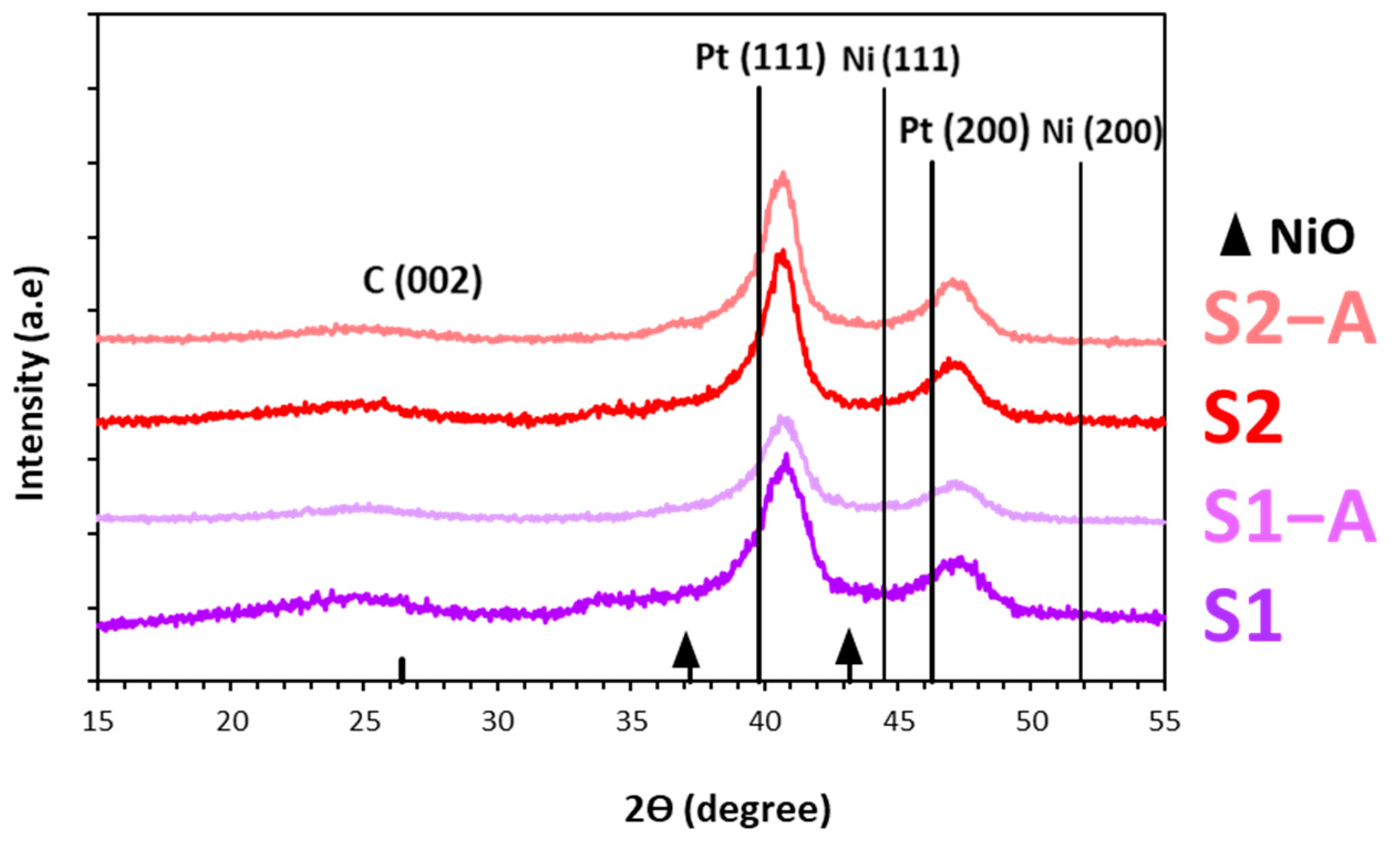
Figure 1. Schematic representation of bimetallic NPs with alloy and core–shell structures in the as-prepared state during the acid treatment and after the acid treatment. Platinum atoms are indicated in blue; nickel d-metal atoms are indicated in pink.
Energies 16 06078 g001
Figure 2. X-ray diffraction patterns of the obtained bimetallic catalysts. Positions of the standard reflections for Pt, Ni, and NiO are indicated.
Energies 16 06078 g002
Figure 3. TEM micrographs of the S1 (a,b), S2 (c,d), S1–A (e,f) and S2–A (g,h) samples as well as histograms of the NPs’ size distribution for the corresponding samples.
Energies 16 06078 g003
Figure 4. EDX maps of Ni and Pt distribution for the PtNi/C materials: S1 (a), S2 (b), S1–A (c), and S2–A (d). STEM micrographs of the PtNi/C samples as well as Pt and Ni line profiles obtained via scanning NPs in the corresponding materials: S1 (e), S2 (f), S1–A (g), S2–A (h). The red lines show the direction of NPs’ scanning.
Energies 16 06078 g004
Figure 5. Photographs of the catalytic layer at the end face of the RDE. Changes in the catalytic layer quality when optimizing the catalytic ink composition: (a) inks prepared according to the composition for the Pt/C catalysts; (b) IPA:H2O = 2:1; (c) IPA:H2O = 1:1; (d) IPA:H2O = 1:2.
Energies 16 06078 g005
Figure 6. CVs of the activation stage for the PtNi/C and Pt/C catalysts. In total, 100 cycles in the potential range of 0.04–1.00 V (ae): S1 (a), S1–A (b), S2 (c), S2–A (d) and JM20 (e). The potential sweep rate is 200 mV s−1. Atmosphere of Ar, 0.1 M HClO4. Cyclic voltammograms at the potential sweep rate of 20 mV s−1 (f,i) for the samples activated in the potential range of 0.04–1.00 V and in an Ar atmosphere: S1 and S1–A (f); S2 and S2–A (i). Linear sweep voltammograms of the oxygen electroreduction in the studied catalysts at the RDE rotation speed of 1600 rpm, at the potential sweep rate of 20 mV s−1 and in an O2 atmosphere (g,j): S1 and S1–A (g); S2 and S2–A (j). 0.1 M HClO4. Dependence 1/j of ω−1/2 at the potential of 0.90 V (h,k): S1 and S1–A (h); S2 and S2–A (k). CVs, LSVs and dependence 1/j of ω−1/2 for the commercial Pt/C analog are indicated in gray.
Energies 16 06078 g006
Figure 7. Histograms of the ORR mass activity and the ECSA for the S2–A sample and the commercial analog JM20 after accelerated stress testing within the start/stop protocol.
Energies 16 06078 g007
Table 1. Composition and structural characteristics of the obtained PtNi/C catalysts.
Sampleω(Pt+NiO), % Mass.Average Crystallite Diameter, DAv, nm
(XRD)
Average Diameter of NPs, nm
(TEM)
Composition According to the Vegard’s Law, PtNix
S141.64.04.90.25
S238.75.66.60.21
S1–A26.04.66.40.24
S2–A30.65.96.70.21
Table 2. Electrochemical characteristics of the activated PtNi/C catalysts.
SampleECSA (Hads),
m2 gPt−1
Ik, mAImass, A gPt−1E1/2, V
S1200.81570.90
S1–A331.63200.91
S2261.53170.92
S2–A302.03890.92
JM20781.22480.90
Disclaimer/Publisher’s Note: The statements, opinions and data contained in all publications are solely those of the individual author(s) and contributor(s) and not of MDPI and/or the editor(s). MDPI and/or the editor(s) disclaim responsibility for any injury to people or property resulting from any ideas, methods, instructions or products referred to in the content.

