Article

Control of an Offshore Wind Farm Considering Grid-Connected and Stand-Alone Operation of a High-Voltage Direct Current Transmission System Based on Multilevel Modular Converters

by
Matheus Sene Paulo
1,†,
Andrei de Oliveira Almeida
2,
Pedro Machado de Almeida
1 and
Pedro Gomes Barbosa
1,*,†
1
Graduate Program of Electrical Engineering, Federal University of Juiz de Fora, Juiz de Fora 36036-900, Brazil
2
Department of Electric and Electronics, Federal Centre of Technological Education of Minas Gerais, Leopoldina 36700-001, Brazil
*
Author to whom correspondence should be addressed.
These authors contributed equally to this work.
Energies 2023, 16(16), 5891; https://doi.org/10.3390/en16165891
Submission received: 5 July 2023 / Revised: 25 July 2023 / Accepted: 7 August 2023 / Published: 9 August 2023
(This article belongs to the Section A1: Smart Grids and Microgrids)

Abstract

:
This work presents a control strategy for integrating an offshore wind farm into the onshore electrical grid using a high-voltage dc transmission system based on modular multilevel converters. The proposed algorithm allows the high-voltage DC system to operate in grid-connected or stand-alone modes, with the second case supplying power to local loads. In either mode, the modular multilevel rectifier works as a grid-forming converter, providing the reference voltage to the collector network. During grid-connected operation, the modular multilevel inverter regulates the DC link voltage while the generating units are controlled to maximize power extracted from the wind turbines. Conversely, in the event of grid disconnection, the onshore modular multilevel converter takes over the regulation of the AC voltage at the point of connection to the grid, ensuring energy supply to local loads. Simultaneously, the generator controller transitions from tracking the maximum power of the wind turbines to regulating the DC link voltage, preventing excessive power injection into the transmission DC link. Additionally, the turbine pitch angle control regulates the speed of the generator. Mathematical models in the synchronous reference frame were developed for each operation mode and used to design the converter’s controllers. A digital model of the wind power plant and a high-voltage dc transmission system was implemented and simulated in the PSCAD/EMTDC program. The system modeled includes two groups of wind turbines, generators, and back-to-back converters, in addition to a DC link with a rectifier and an inverter station, both based on modular multilevel converters with 18 submodules per arm, and a 320 k V /50 k m DC cable. Aggregate models were used to represent the two groups of wind turbines, where 30 and 15 smaller units operate in parallel, respectively. The performance of the proposed control strategy and the designed controllers was tested under three distinct scenarios: disconnection of the onshore converter from the AC grid, partial loss of a wind generator set, and reconnection of the onshore converter to the AC grid.

1. Introduction

In recent decades, concerns about reducing greenhouse gas emissions and the depletion of fossil fuel sources have led to a growing interest in renewable energy sources in several countries worldwide [1]. Modern high-power wind energy conversion systems (WECSs) can be installed in onshore and offshore sites. However, the availability of large areas for installation, higher and more constant wind speeds, and easier logistics for transporting and building large turbines make offshore facilities more attractive compared to onshore [2].
Nevertheless, the growing interest in offshore wind farms presents several challenges in terms of integrating these systems into the electrical grid. Although high-voltage AC (HVAC) transmission is currently predominant for offshore wind farm integration, there is considerable interest in exploring and studying high-voltage dc (HVDC) transmission systems [3,4]. Different topologies of voltage source converters (VSCs) can be used for HVDC transmission. VSC-HVDC technology has advantages, such as lower losses over longer distances, independent control of active and reactive power, and virtual inertia support, aiding in the recovery after network failures [5].
Figure 1 shows an example of a VSC-HVDC offshore wind farm export system. Each WECS is composed of a wind turbine (WT), a permanent magnet synchronous generator (PMSG), a back-to-back (B2B) three-phase VSC, and an isolation transformer. The WECS units are connected to a collector network, supplying energy to an offshore station, where a step-up transformer increases the voltage to the transmission level. Then, a rectifier converts the voltages and currents to dc, transmitting the energy through subsea dc cables to the onshore station. The voltages and currents are converted to AC by the inverter, to be injected into the AC network through an overhead transmission line.
The onshore and offshore HVDC converters shown in Figure 1 are modular multilevel converters (MMC) [6]. The modular structure enables the MMC to efficiently handle high voltage levels, eliminating the requirement for intricate and bulky interconnect transformers. Moreover, the MMC allows for the production of multilevel voltages with minimal harmonic content, eliminating the need for complex passive filters connected to its output terminals [7,8,9].
In this scenario, the interaction between the MMC and the AC grid has been widely analyzed in the literature. Li et al. [10] propose a two-stage voltage drop control scheme for offshore MMC to achieve fast active power reduction and mitigate dc overvoltage during a fault and post-fault dc voltage restoration. In [11], high-frequency resonances in the MMC are analyzed, and two optimized methods regarding the current control loop are presented to address this issue. Wang, Zhao, and Guo [12] present a comparative analysis of the operational stability of the MMC-HVDC station operating in different control modes. The authors benefit from a comprehensive dynamic-phasor-based state-space model of MMC to obtain four linearized small-signal models for the converters and compare their responses. However, all these analyses take into account only the converters operating in isolation. The connection of the MMC via an HVDC system is not considered.
Different control strategies for MMC-HVDC systems have been extensively proposed in the literature. In [13], the authors develop an energy-based control of the MMC-HVDC system to interconnect two non-synchronous AC grids. The proposed strategy achieves full control of the converter’s inner dynamics, regardless of the dc line length. Belahouane et al. [14] design a robust control to reject uncertainties on the AC side of the MMC. In a recent study by Lourenço et al. [15], the authors examine the stability of a grid-connected network when a MMC-HVDC system operates in grid-forming mode. The analysis employs energy functions and Lyapunov theory to assess the system’s stability. Dadjo et al. [16] investigate the dynamic behavior of an MMC-HVDC link using a state-space model. The goal was to identify critical modes for system operation. Additionally, in [17], the authors provide a comprehensive investigation and review of control strategies for MMC-HVDC systems. Nonetheless, none of these works include WECS systems in their analyses.
Offshore WECS connected through MMC-HVDC systems are analyzed in [18,19,20]. Zeng et al. [18] discuss the coordinated control of an MMC-HVDC system and an offshore wind farm to provide emulated inertia support through the use of the energy stored in the dc capacitors of the converters. In [19], a coordinated control method based on the injection of harmonics is proposed to provide fault ride-through (FRT) capability to the WECS. In [20], the authors present a positive and negative sequence-based current control strategy to comply with the grid code requirements during balanced and unbalanced faults in the AC grids. Similarly, in [21], the authors introduce a novel synthetic inertia controller that fulfills the requirements of the AC network. It also provides a comprehensive classification and summary of existing inertia controllers. However, it is worth noting that all papers mentioned above focus exclusively on grid-connected operation and do not consider stand-alone operation.
In a study conducted by Kazemi et al. [22], a control strategy for wind turbines is proposed to regulate the load frequency in isolated electrical networks. The authors address the challenges of operating wind turbines in islanded grids. Additionally, Kamal et al. [23] present the islanded operation of a microgrid that incorporates multiple wind turbines based on a PMSG and energy storage devices. They implement a grid-forming strategy in the PMSG converters, enabling network operation with energy storage systems.
In [24], the authors propose an optimized real-time dispatch strategy for automatic generation control (AGC). The strategy uses the storage capacity of electric vehicles to allocate the regulatory reserves of wind farms, reducing the operating cost of the system and allowing conventional power plants to operate with lower limits. Asghar et al. [25] investigate recent advances in load frequency control (LFC) techniques for wind-based power systems. Several techniques are analyzed and compared to evaluate the advantages and disadvantages of different controllers in order to support future developments of LFC in wind energy.
In [26], the authors implement the conventional droop control to achieve grid-connected and stand-alone operating modes for onshore wind turbines. The study introduces a novel approach involving the coordinated control of generator speed and blade pitch angle, along with a dc voltage controller for the interface converter. Additionally, the grid-side converter works as a voltage source to help regulate the terminal voltage amplitude and frequency. However, none of the previous works discuss the coordinated control of the wind farm and the MMC-HVDC.

Motivation and Contribution of the Work

Therefore, this work presents a control algorithm designed explicitly for an MMC-HVDC transmission system to integrate offshore wind farms. The algorithm enables correct operation in both grid-connected and stand-alone modes, enhancing the flexibility and reliability of the system. The main contributions can be summarized as follows:
(i)
Mathematical Models: the compilation of a set of linearizing models for MMC-HVDC and WECS units in the synchronous reference frame, allowing for a comprehensive representation of the system’s dynamic behavior, both for grid-connected and stand-alone modes of operation. Furthermore, the study presents a detailed description of the closed-loop transfer functions of the HVDC converters and wind generator units, enabling the design of effective control systems for the overall system. These mathematical models serve as valuable tools for analyzing and optimizing the performance of the interconnected components in various operating conditions.
(ii)
Grid-Connected Operation: during grid-connected operation, the control algorithm ensures the proper regulation of the onshore MMC’s DC link voltage while optimizing power generation from the wind turbines. The generating units are controlled to track the maximum power output of the wind turbines, improving the overall system efficiency.
(iii)
Stand-Alone Operation: in the event of disconnection from the grid, the control algorithm allows for a smooth transition to stand-alone operation. The onshore converter takes over the AC voltage regulation at the point of common coupling (PCC), ensuring a continuous power supply for local loads. Additionally, the wind generator control adjusts its operation from tracking maximum power to regulating the DC link voltage, preventing excessive power injection into the HVDC link. The pitch angle control of the wind turbines is employed to maintain a fixed generator speed.
(iv)
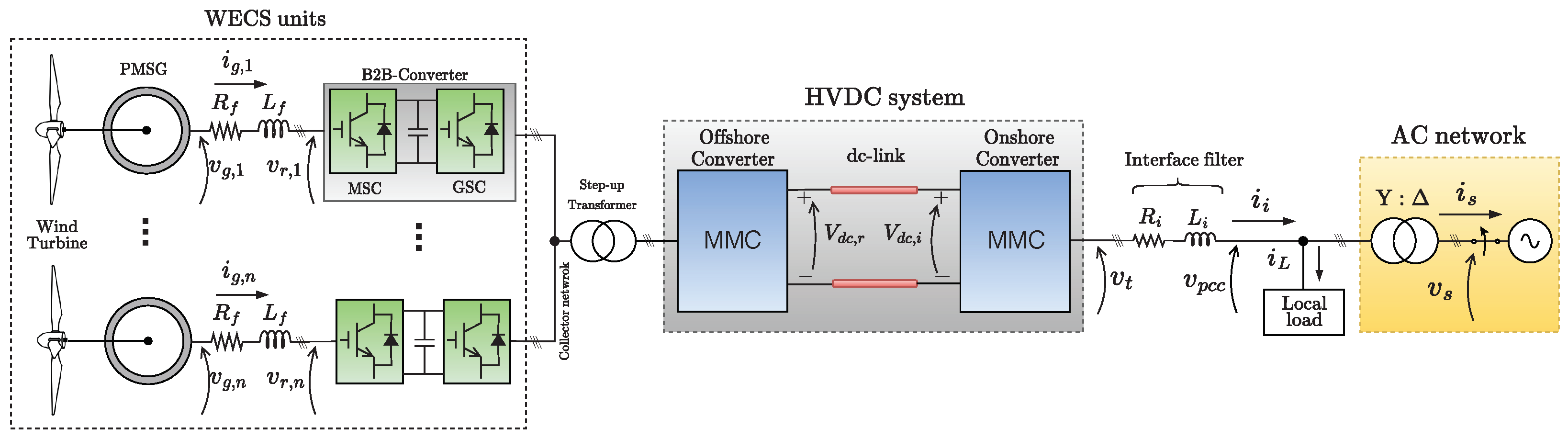
Digital Simulation: the work develops a detailed digital model to analyze the performance of the wind energy system, incorporating wind-generating units, MMC-based rectifier and inverter stations, back-to-back converters, and a 320 k V /50 k m DC cable.
(v)
Evaluation and Testing: to assess the performance of the proposed control strategy, the developed model is implemented and simulated using the PSCAD/EMTDC program. The system’s dynamic behavior is tested under different scenarios, including grid disconnection, partial loss of a group of wind generating units, and grid reconnection. These simulations provide valuable insights into the system’s performance and validate the control algorithm’s effectiveness.
Overall, this work contributes to advancing the integration of offshore wind farms through the development of a control algorithm, comprehensive system modeling, and thorough evaluation through simulations. The rest of this paper is organized as follows: Section 2 presents the mathematical modeling of the four converters and their control loops design, considering the grid-connected operation of the HVDC system; following, Section 3 presents the onshore MMC and the PMSG control strategies for the stand-alone mode, including the wind turbine pitch control; Section 4 presents results of digital simulation studies obtained with the PSCAD/EMTDC considering previously designed converter models and controllers; finally, Section 5 presents the conclusions and the final considerations.

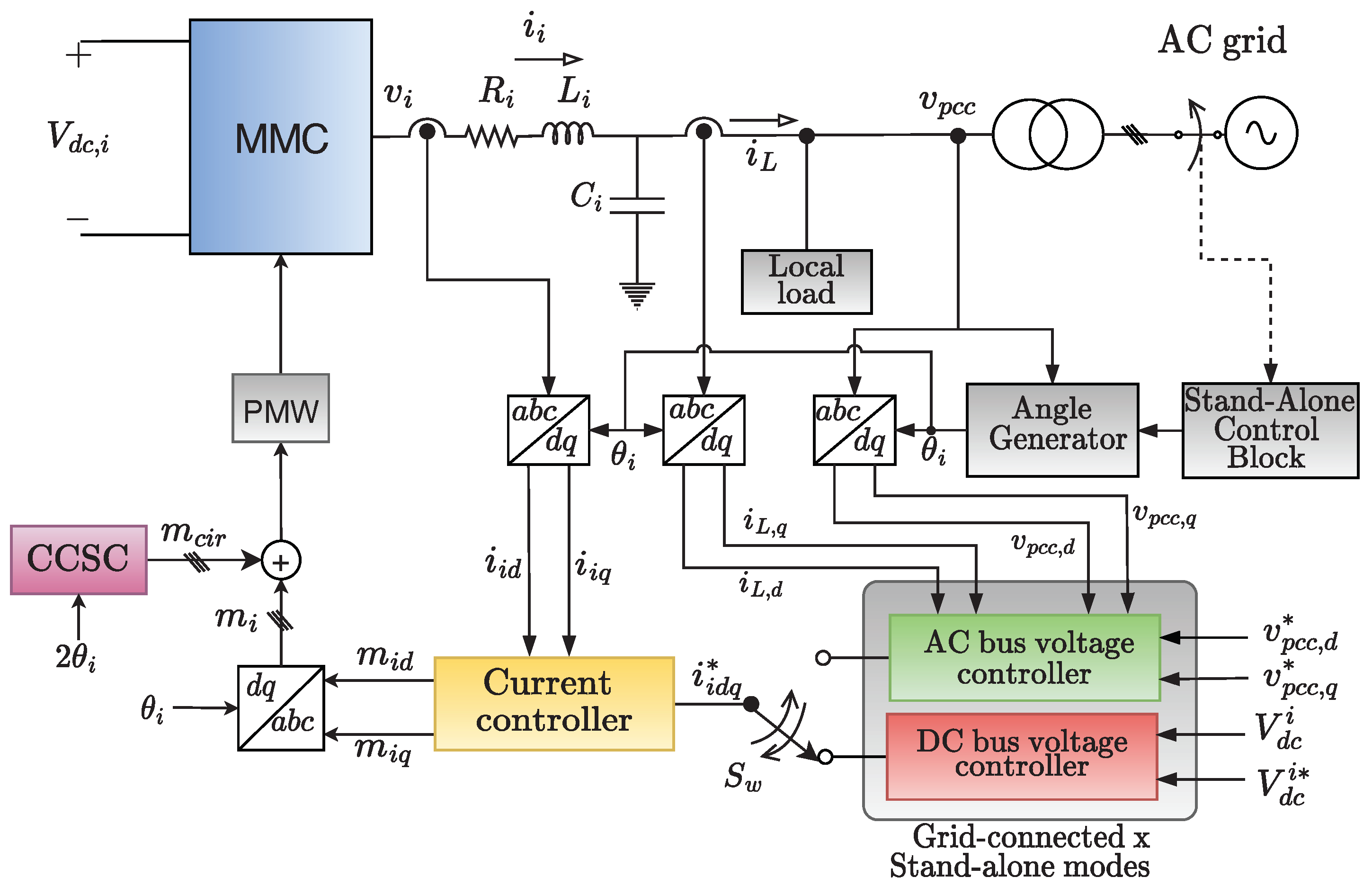
2. Control Strategy for Grid-Connected HVDC

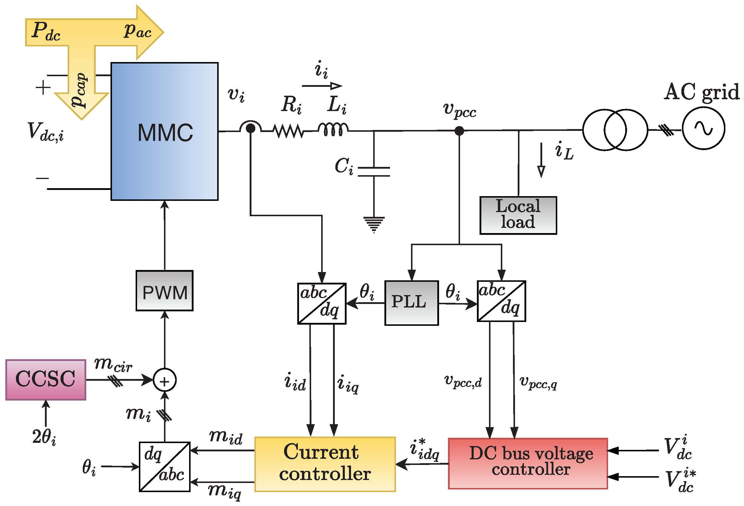
2.1. Onshore MMC Control

Figure 2 shows the control block diagram of the onshore MMC connected to a power system. In addition, there is a local load connected to the onshore MMC’s PCC. During the grid-connected operation, the converter regulates the HVDC link voltage, injecting power into the mains. A phase-locked loop (PLL) synchronizes the voltages and currents at the MMC terminals with the PCC voltages [27]. A circulating current-suppressing controller (CCSC) based on the double-fundamental frequency was designed in the synchronous reference frame (SRF) to reduce the amplitudes of the circulating current [28].

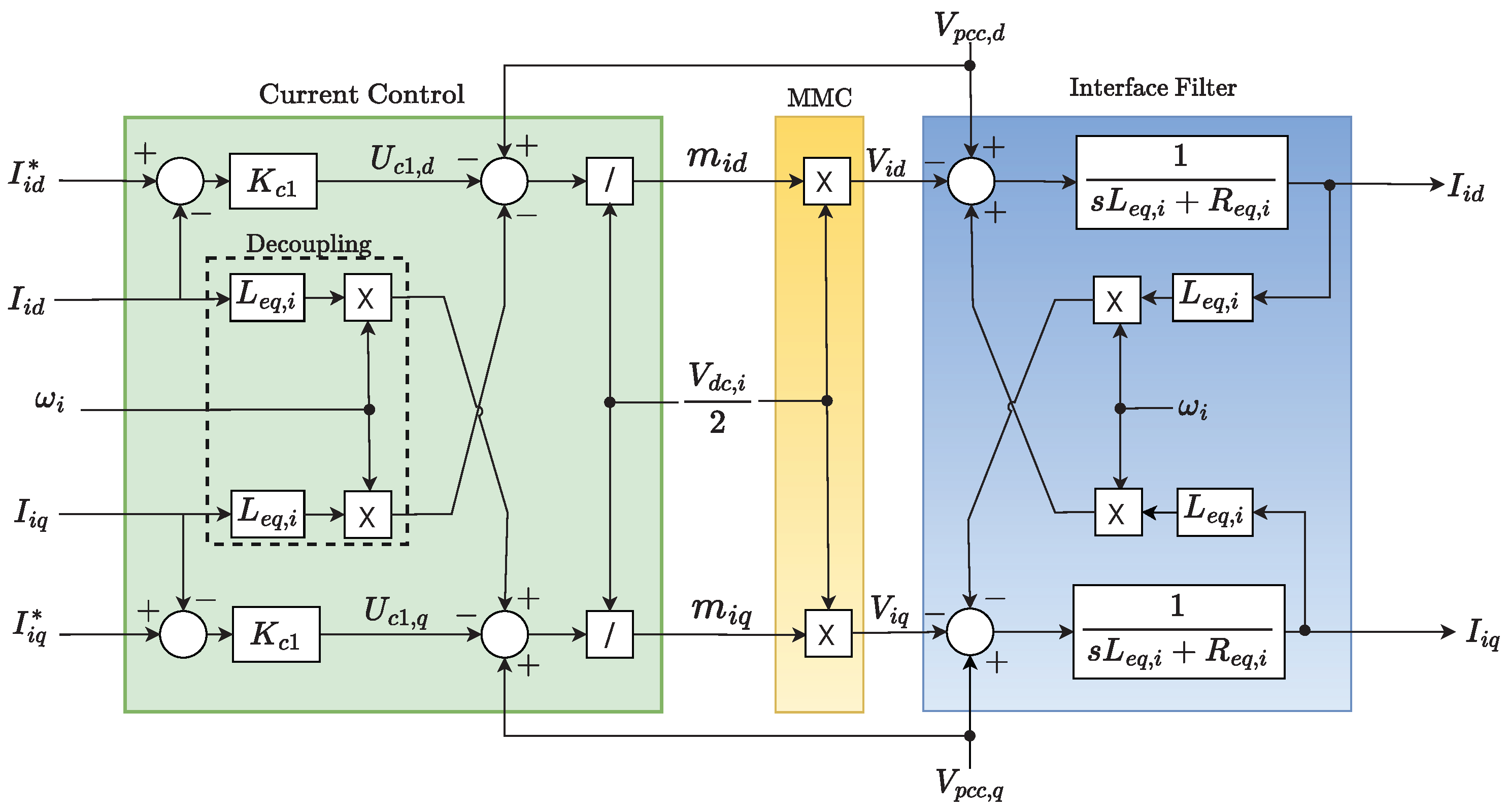
2.1.1. AC Current Control

Bearing in mind the polarities of voltages and currents shown in Figure 2, the following dynamic equations can be written, in d q coordinates, for the currents synthesized by the onshore MMC [29]:
v i , d v p c c , d + ω i L e q , i i i , q = L e q , i d i i , d d t + R e q , i i i , d
v i , q v p c c , q ω i L e q , i i i , d = L e q , i d i i , q d t + R e q , i i i , q
where i i , d and i i , q are the instantaneous currents of the direct and quadrature axes, synthesized by the onshore MMC, respectively; v t , d and v t , q are the direct and quadrature axes voltages at the onshore MMC terminals, respectively; v p c c , d and v p c c , q are the direct and quadrature axes voltages at the PCC, respectively; ω i is the angular frequency of the PCC voltages; R e q , i = R i + R a r m / 2 and L e q , i = L i + L a r m / 2 are the equivalent resistance and inductance of the MMC, R a r m and L a r m being the resistance and inductance of the arms, respectively; and R i and L i are the resistance and inductance of the interface filter. The zero-axis voltage and current were omitted in the above model since the MMC has three wires.
Neglecting the switching harmonics and replacing v i , d = m i , d ( V d c , i / 2 ) and v i , q = m i , q ( V d c , i / 2 ) in Equations (1) and (2), it is possible to write the simplified control laws for the MMC [30]:
m i , d = 2 V d c , i u i , d + v p c c , d ω i L e q , i i i , q ,
m i , q = 2 V d c , i u i , q + v p c c , q + ω i L e q , i i i , d ,
where m i , d and m i , q are the direct and quadrature axes modulation indexes for a PWM sinusoidal strategy, respectively; V d c , i is the DC link bus voltage of the onshore MMC; u i , d and u i , q are the direct and quadrature axes new control variables, respectively.
Applying the Laplace transform to Equations (1)–(4), and combining the results obtained, it is possible to draw the block diagram shown in Figure 3, where PI-controllers can be easily designed to regulate the currents I i , d ( s ) and I i , q ( s ) . The cross-coupling between the dq-axes currents is eliminated by the internal decoupling loop. The terms V p c c , d and V p c c , q mitigate the influence of the PCC voltage on the currents synthesized by the MMC. I i , d * ( s ) and I i , q * ( s ) are reference signals that must be tracked.
Therefore, based on Figure 3, similar closed-loop transfer functions can be written for the dq-currents:
G c 1 , d q ( s ) = I i , d q I i , d q * = s k p , c 1 L e q , i + k i , c 1 L e q , i s 2 + s k p , c 1 + R e q , i L e q , i + k i , c 1 L e q , i ,
where k p , c 1 and k i , c 1 are the proportional and integral gains of the current PI-controllers K c 1 ( s ) of the inverter, respectively.
The comparison of the Equation (5) denominator with the canonical form of a second-order transfer function ( s 2 + 2 s ζ c 1 ω c 1 + ω c 1 2 ) allows for choosing the gains k p , c 1 and k i , c 1 as follows:
k p , c 1 = 2 ζ c 1 ω c 1 L e q , i R e q , i and k i , c 1 = ω c 1 2 L e q , i
where ω c 1 is the undamped natural frequency and ζ c 1 is the damping factor of the closed-loop transfer function described in Equation (5).

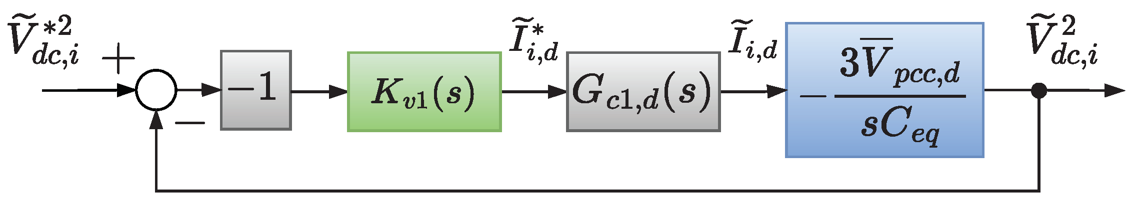
2.1.2. DC-Link Voltage Control

Considering the grid-connected operation mode and neglecting the internal losses of the MMC, the following energy balance equation can be written for the onshore converter in Figure 2 [31]:
C e q 2 d V d c , i 2 d t = P d c , i 3 2 v p c c , d i i , d ,
where ( C e q / 2 ) ( d V d c , i 2 / d t ) is the power stored in the equivalent dc-capacitor of the onshore MMC; C e q = 3 C s m , i / N i + 3 C s m , r / N r is the equivalent dc capacitance; C s m , i and C s m , r are the capacitance of the MMC onshore and offshore submodules, respectively; N i and N r are the number of active submodules per phase of MMC onshore and offshore, respectively; P d c , i is the power supplied by the DC link; and ( 3 / 2 ) v p c c , d i i d is the power injected into the AC grid by the onshore MMC. The PLL ensures that the voltage v p c c is synchronized with the d-axis.
Linearizing Equation (7) and applying the Laplace transform to the resulting expression, the following relation is obtained [32]:
V ˜ d c , i 2 ( s ) = 2 s C e q P ˜ d c , i ( s ) 3 V ¯ p c c , d 2 I ˜ i , d ( s )
The symbols (   ˜ ) and (   ¯ ) represent, respectively, the steady-state and small-deviation values of the electrical quantities around the operational point. Considering Equation (8), one can draw the control block diagram of Figure 4. For simplicity, the signal P ˜ d c , i ( s ) is not included in the diagram. The block denoted by K v 2 ( s ) represents the dc-voltage controller of the onshore MMC, while G c 1 , d ( s ) corresponds to the closed-loop current transfer function given in Equation (5). Additionally, the block exhibiting a unit negative gain is employed to compensate for the plant signal.
Choosing the gains in Equation (6) so that the cut-off frequency of Equation (5) is at least one decade greater than the cut-off frequency of the closed-loop function transfer of DC link voltage control, G c 1 ( s ) can be approximated by unity gain in Figure 4. Then, the following closed-loop transfer function can be written for the squared value of the DC link voltage:
G v 1 ( s ) = V ˜ d c , i 2 V ˜ d c , i 2 = s 3 V ¯ p c c , d k p , v 1 C e q + 3 V ¯ p c c , d k i , v 1 C e q s 2 + s 3 V ¯ p c c , d k p , v 1 C e q + 3 V ¯ p c c , d k i , v 1 C e q ,
where k p , v 1 and k i , v 1 are, respectively, the proportional and integral gains of the DC link voltage PI-controller K v 1 ( s ) , which are chosen by comparing with the second-order canonical transfer function as follows:
k p , v 1 = 2 ζ v 1 ω v 1 C e q 3 V ¯ i , d and k i , v 1 = ω v 1 2 C e q 3 V ¯ i , d ,
where ω v 1 is the undamped natural frequency and ζ v 1 is the damping factor of the closed-loop transfer function of the inverter dc-voltage control.
As shown above, the current I ˜ i , d is used to force the MMC to inject active power into the AC network to regulate the DC link voltage of the inverter during the grid-connected operation mode. At the same time, the I ˜ i , q is equal to zero since the MMC inverter does not compensate reactive power at its terminals. However, in practical applications, the onshore MMC can also be controlled to provide reactive power support. In this case, the PCC voltage V p c c can be controlled by the current component I i , q [33].

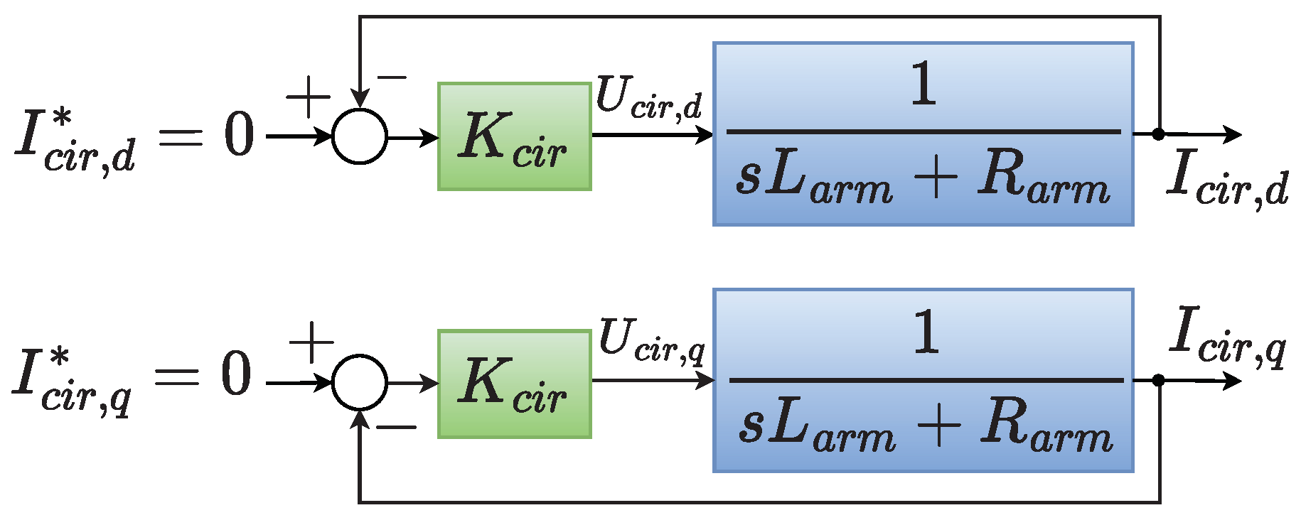
2.1.3. Circulating Current Suppressing Controller

Neglecting the effect of the current dc component since the dc bus controller will regulate it, the dynamic behavior of the circulating current can be described as [34]:
v i m , d = R a r m i c i r , d + L a r m d i c i r , d d t + 2 ω i L a r m i c i r , q
v i m , q = R a r m i c i r , q + L a r m d i c i r , q d t 2 ω i L a r m i c i r , d ,
where v i m , d = m c i r , d ( V d c , i / 2 ) and v i m , q = m c i r , q ( V d c , i / 2 ) are the direct and quadrature axes inner unbalance voltages, respectively; m c i r , d and m c i r , d are, respectively, the direct and quadrature axes insertion index due to the unbalance voltages; and i c i r , d and i c i r , q are the direct and quadrature axes circulating currents, respectively.
Defining the control variables u c i r , d and u c i r , d , one can write the following control relations [35]:
m c i r , d = 2 V d c , i u c i r , d + 2 ω i L a r m i c i r c , q ,
m c i r , q = 2 V d c , i u c i r , q 2 ω i L a r m i c i r c , d .
Substituting Equation (13) into Equation (11) and Equation (14) into Equation (12), the cross-coupling between the direct and quadrature-axes currents are eliminated, resulting in the following first-order dynamic system:
d i c i r , d d t = R a r m L a r m i c i r , d + 1 L a r m u c i r , d
d i c i r , q d t = R a r m L a r m i c i r , q + 1 L a r m u c i r , q
Applying the Laplace transform to Equations (15) and (16), it is possible to draw the block diagrams of Figure 5, where PI-controllers are easily designed to regulate the currents I c i r , d ( s ) and I c i r , q ( s ) . The currents I c i r , d * ( s ) and I c i r , q * ( s ) are reference signals that must be tracked.
Then, the following closed-loop transfer function can be written:
G c i r , d q ( s ) = I c i r , d q ( s ) I c i r , d q ( s ) = 1 / L a r m k c i r , p s + k c i r , i s 2 + s k c i r , p + R a r m L a r m + k c i r , i L a r m ,
where k c i r , p and k c i r , i are the proportional and integral gains of the controller K c i r ( s ) , respectively, which are chosen by comparing Equation (17) with the second-order canonical transfer function as follows:
k c i r , i = ω c i r 2 L a r m and k c i r , p = 2 ζ c i r ω c i r L a r m R a r m .
where ω c i r c is the undamped natural frequency and ζ c i r c is the damping factor of the closed-loop transfer function.

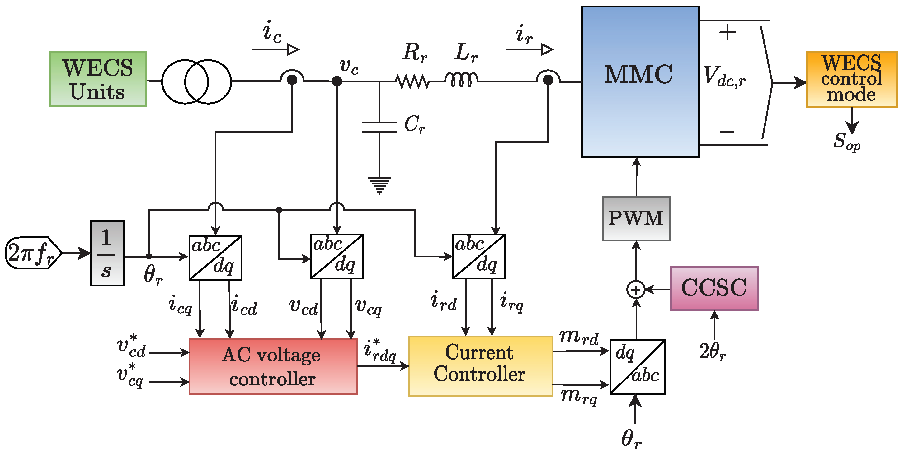
2.2. Offshore MMC Control

The control diagram of the offshore MMC is depicted in Figure 6. Regardless of the HVDC system operating mode, the offshore MMC works as a grid-forming converter for the wind generating units, imposing voltage to the collector network. Therefore, an AC voltage control loop was designed to fulfil this goal. The CCSC strategy is the same as the one presented for the onshore MMC. The angle θ r used in the a b c d q transformations is generated by an integrator fed at a constant angular frequency ω = 2 π f r , where f r = 60 Hz .
The WECS Control Mode block is responsible for monitoring the converter’s dc-voltage. If the dc-voltage reaches 110% of its rated value, the signal S o p is sent to the WECS units to change the wind generator’s mode of control.

2.2.1. AC Current Control

The design of the inner current control loop is very similar to the one presented for the onshore MMC. Considering the polarities of voltages and currents shown in Figure 6, the following dynamic equations can be written, in d q coordinates, for the terminal currents of the offshore MMC:
v c d v r d + ω r L e q , r i r q = L e q , r d i r d d t + R e q , r i r d ,
v c q v r q ω r L e q , r i r d = L e q , r d i r q d t + R e q , r i r q ,
where i r , d and i r , q are the instantaneous currents of the direct and quadrature axes, synthesized by the offshore MMC, respectively; v r , d and v r , q are the direct and quadrature axes voltages at the offshore MMC, respectively; v c , d and v c , q are the direct and quadrature axes voltages at the AC bus, respectively; ω R is the angular frequency of the AC bus voltages; R e q , r = R r + R a r m / 2 and L e q , r = L r + L a r m / 2 are the equivalent resistance and inductance of the MMC, R a r m and L a r m being the resistance and inductance of the arms, respectively; and R r and L r the resistance and inductance of the interface filter. The zero-axis voltage and current were omitted in the above model since the MMC has three wires.
Neglecting the switching harmonics and replacing v r , d = m r , d ( V d c , r / 2 ) and v r , q = m r , q ( V d c , r / 2 ) in Equations (19) and (20) allows us to write the following control relations for the offshore MMC:
m r , d = 2 V d c , r u r , d + v c , d + ω r L e q , r i r , q ,
m r , q = 2 V d c , r u r , q + v c , q ω r L e q , r i r , d ,
where m r , d and m r , q are the direct and quadrature axes modulation indexes for a PWM sinusoidal strategy, respectively; V d c , r is the DC link bus voltage of the offshore MMC; u r , d and u r , q are the direct and quadrature axes new control variables, respectively.
Thus, PI-controllers can be efficiently designed to regulate the currents i r , d and i r , q . Applying the Laplace transform to Equations(19)–(22) and combining the results obtained, similar closed-loop transfer functions can be written for the dq-currents:
G c 2 , d q ( s ) = I r , d q ( s ) I r , d q * ( s ) = 1 / L e q , r ( s k p , c 2 + k i , c 2 ) s 2 + s k p , c 2 + R e q , r L e q , r + k i , c 2 L e q , r ,
where k p , c 2 and k i , c 2 are the proportional and integral gains of the current PI-controllers of the rectifier K c 2 ( s ) , respectively.
Comparing the denominator of (23) with the canonical form of a second-order transfer function, the gains are obtained as:
k p , c 2 = 2 ζ c 2 ω c 2 L e q , r R e q , r and k i , c 2 = ω c 2 2 L e q , r
where ω c 2 is the undamped natural frequency and ζ c 2 is the damping factor of the closed-loop transfer function of the converter current control.

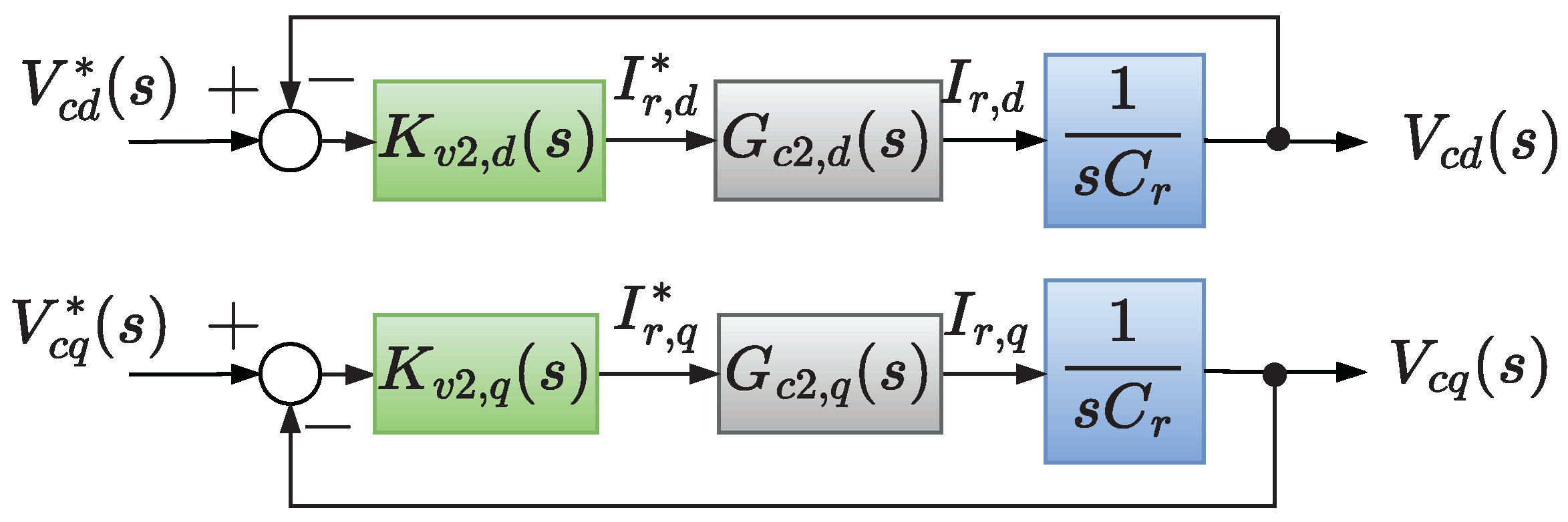
2.2.2. Collector Network Voltage Control

Based on Figure 6, the dynamics equations of the AC bus voltages are [36]:
C r d d t v c d = i c d i r d + C r ω r v c q ,
C r d d t v c q = i c q i r q C r ω r v c d ,
where i c d and i c q are the direct and quadrature axes instantaneous currents injected into the collector network.
Defining the control variables u v 2 , d and u v 2 , q , from Equations (25) and (26), one can write the following relations for the AC bus voltages:
i r , d * = u v 2 , d + ω r C r v c , q + i c , d ,
i r , q * = u v 2 , q ω r C r v c , d + i c , q .
Applying the Laplace transform to Equations (25)–(28) and combining the results obtained, it is possible to draw the block diagram shown in Figure 7, where PI-controllers are easily designed to regulate the voltages V c , d ( s ) and V c , q ( s ) . V c , d * ( s ) and V c , q * ( s ) are reference signals that must be tracked.
Based on the Figure 7 block diagram, one can write:
G c 2 ( s ) U v 2 , d ( s ) + 1 G c 2 ( s ) ω r C r V c , q ( s ) + 1 G c 2 ( s ) I c , d ( s ) = s C r V c , d ( s ) ,
G c 2 ( s ) U v 2 , q ( s ) 1 G c 2 ( s ) ω r C r V c , d ( s ) + 1 G c 2 ( s ) I c , q ( s ) = s C r V c , q ( s ) .
Assuming again that the cut-off frequency of Equation (23) is large enough to make G c 2 ( s ) = 1 in Equations (29) and (30) for the frequency of operation, the cross-coupling between the direct and quadrature axes AC bus voltages is eliminated. The terms I c , d ( s ) and I c , q ( s ) mitigate the influence of the collector network currents on the control variables U v 2 , d ( s ) and U v 2 , q ( s ) . Figure 8 shows a diagram of the decoupled control block used to regulate the AC bus voltages during the stand-alone operation mode, allowing us to write the following closed-loop transfer function:
G v 2 , d q ( s ) = V c , d q ( s ) V c , d q * ( s ) = s k p , v 2 C r + k i , v 2 C r s 2 + s k p , v 2 C r + k i , v 2 C r ,
where k p , v 2 and k i , v 2 are, respectively, the proportional and integral gains of the AC voltage PI-controller, which are chosen by comparing with the canonical transfer function second-order as follows:
k p , v 2 = 2 ζ v 2 ω v 2 C r and k i , v 2 = ω v 2 2 C r ,
where ω v 2 and ζ v 2 are, respectively, the natural undamped frequency and the damping factor of the closed-loop transfer function of the offshore AC bus voltage control.

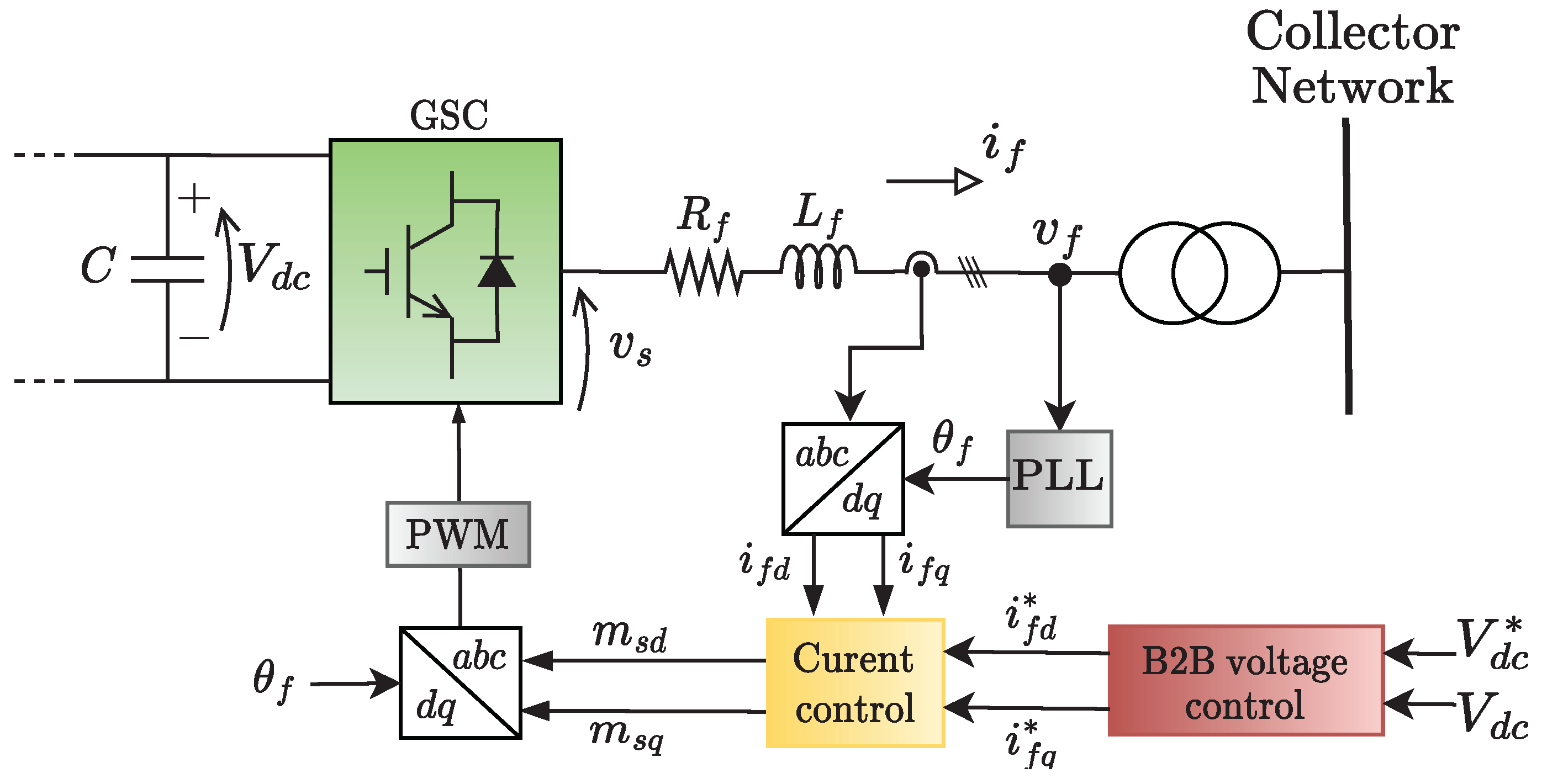
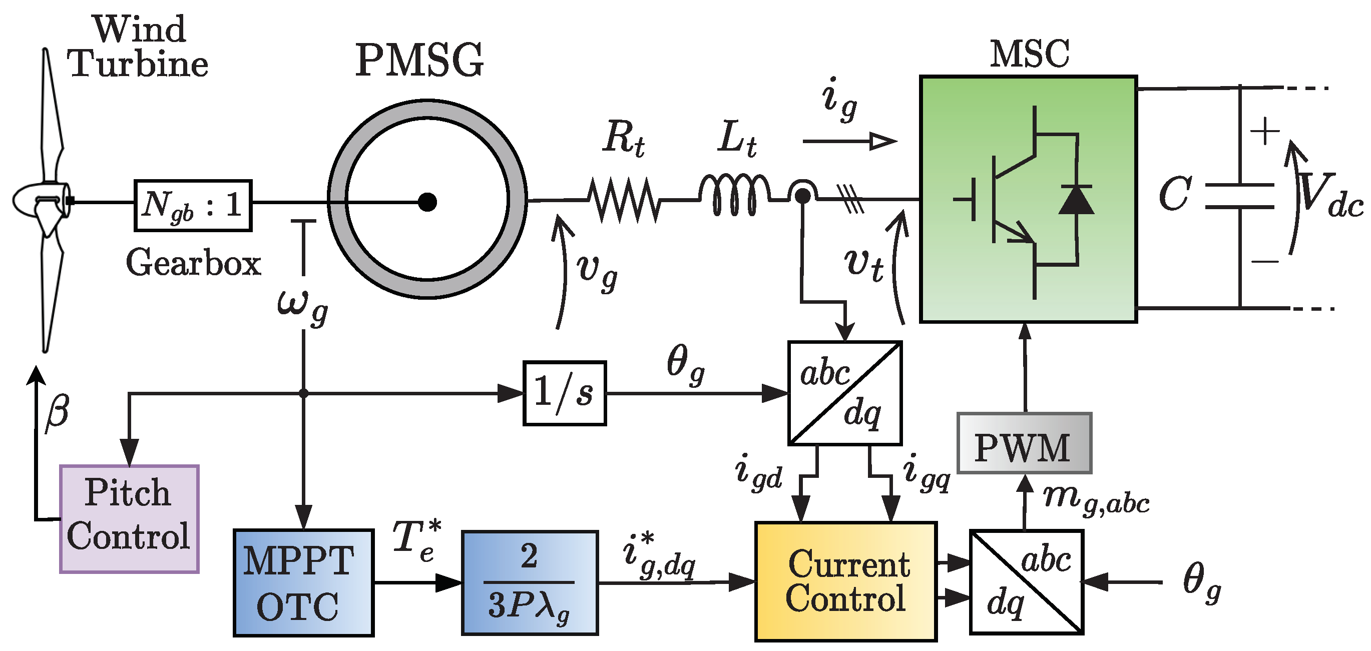
2.3. WEC Grid-Side Converter Control

Regardless of the operation mode, the grid-side converter (GSC) of the WEC unit regulates the dc-bus voltage V d c of the back-to-back converter in a similar way to that explained in Section 2.1.2 for the onshore MMC. Its control block diagram is presented in Figure 9. The converter uses the angle θ f , obtained from the PLL, to synchronize its voltages and currents with the collector network’s voltages.
Considering the polarities of voltages and currents shown in Figure 9, the following dynamic equations can be written [2]:
v s d v f d + ω f L f i f q = L f d i f d d t + R f i f d ,
v s q v f q ω f L f i f d = L f d i f q d t + R f i f q ,
where v s , d and v s , q are the converter terminal voltages of the direct and quadrature axes, respectively; v f , d and v f , q are the collector network voltages of the direct and quadrature axes, respectively; i f , d and i f , q are the currents synthesized by the GSC; L f and R f are the interface filter inductance and resistance, respectively; and ω f is the frequency of the collector network.
Replacing v s d = m s d ( V d c / 2 ) and v s q = m s q ( V d c / 2 ) in Equations (33) and (34), respectively, and then defining two new control variables u c 3 , d and u c 3 , q , it is possible to write the following control relations:
m s d = 2 V d c u c 3 , d ( s ) + v f d ( s ) ω f L f i f q ( s ) ,
m s q = 2 V d c u c 3 , q ( s ) + v f q ( s ) + ω f L f i f d ( s ) ,
where V d c is the dc-voltage of the B2B converter.
Thus, the PI-controllers can be easily designed to regulate the currents i f , d and i f , q . Applying the Laplace transform to Equations (33)–(36) and combining the results obtained, similar closed-loop transfer functions can be written for the dq-currents:
G c 3 , d q ( s ) = I f , d q I f , d q * = s k p , c 3 L f + k i , c 3 L f s 2 + s k p , c 3 + R f L f + k i , c 3 L f ,
where k p , c 3 and k i , c 3 are the proportional and integral gains of the PI-controller, respectively. The gains of the controllers can be obtained through:
k p , c 3 = 2 ζ c 3 ω c 3 L f R f and k i , c 3 = ω c 3 2 L f
where ω c 3 is the undamped natural frequency and ζ c 3 is the damping factor of the closed-loop transfer function of the converter current control.
To design the B2B voltage control, the following power balance equation can be written for the GSC:
C 2 d V d c 2 d t = P d c 3 2 v f , d i f , d ,
where ( C / 2 ) ( d V d c 2 / d t ) is the power stored in the dc-capacitor of the converter; P d c is the power supplied by the machine-side converter (MSC); and ( 3 / 2 ) v f , d i f d is the power injected into the AC grid. Note that the PLL ensures that the voltage v p c c is synchronized with the d-axis.
Linearizing Equation (39) and applying the Laplace transform to the resulting expression, the following relation is obtained:
V ˜ d c 2 ( s ) = 2 s C P ˜ d c ( s ) 3 V ¯ f , d 2 I ˜ f , d ( s )
Once more, a PI-controller can be designed to regulate the converter’s dc-voltage. Thus, by repeating the steps presented in Section 2.1.2, the following closed-loop transfer function can be written:
G v 3 ( s ) = V ˜ d c 2 V ˜ d c * 2 = s 3 V ¯ f , d k p , v 3 C + 3 V ¯ f , d k i , v 3 C s 2 + s 3 V ¯ f , d k p , v 3 C + 3 V ¯ f , d k i , v 3 C ,
where k p , v 3 and k i , v 3 are, respectively, the proportional and integral gains of the B2B dc-voltage PI-controller, which are chosen by comparing with the second-order canonical transfer function as follows:
k p , v 3 = 2 ζ v 3 ω v 3 C 3 V ¯ F , d and k i , v 3 = ω v 3 2 C 3 V ¯ f , d ,
where ω v 3 is the undamped natural frequency and ζ v 3 is the damping factor of the closed-loop transfer function of the inverter dc-voltage control.
As shown above, the current I ˜ i , d forces the GSC to inject active power into the collect network to regulate the B2B dc-voltage. At the same time, the I ˜ i , q is equal to zero since the GSC does not compensate reactive power at its AC terminals.

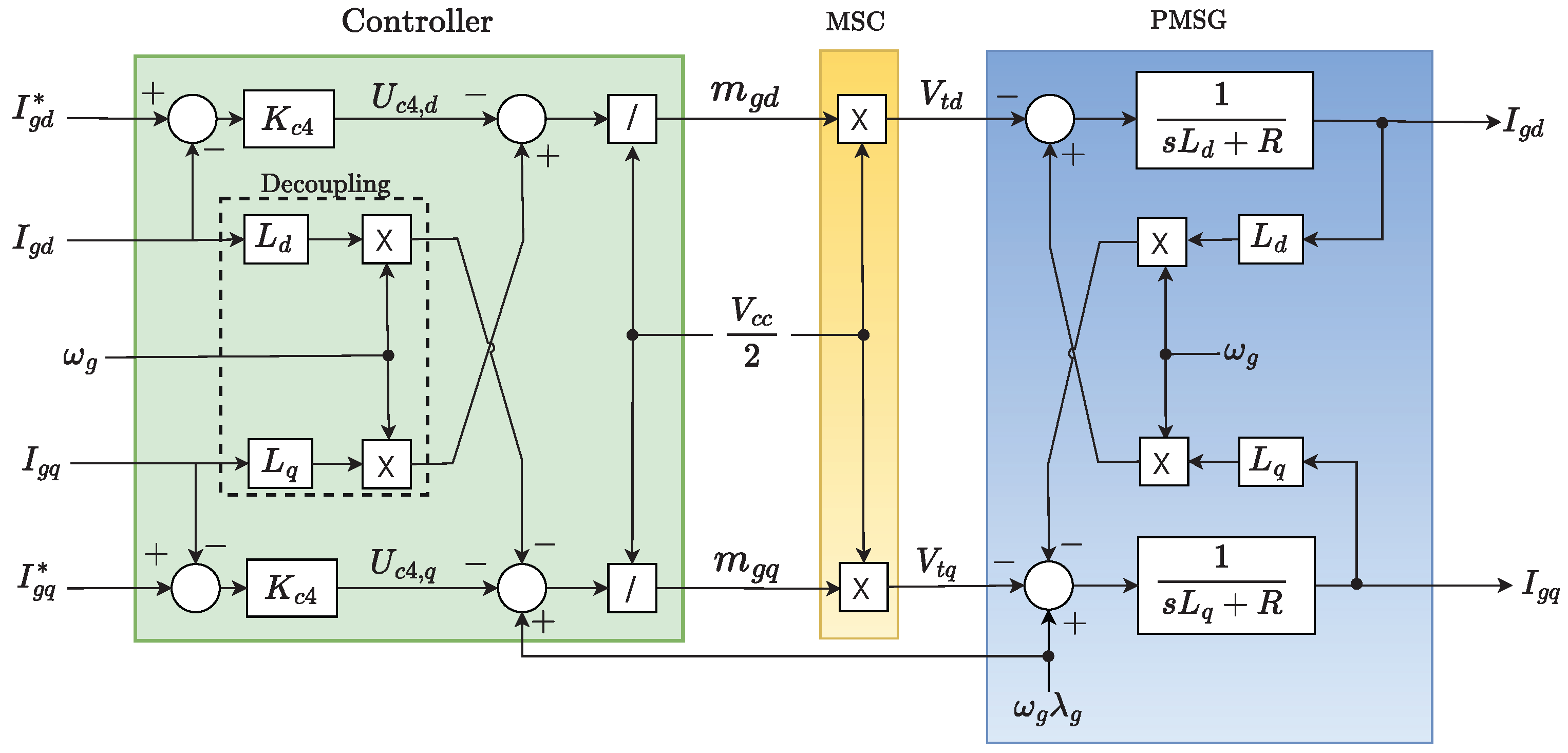
2.4. WEC Machine-Side Converter Control

Figure 10 shows a simplified control block diagram of the PMSG during the grid-connected operation of the HVDC system. The converter uses the angle θ r , measured in the PMSG by an encoder, to synchronize its voltages and currents with the generator’s voltages. During the grid-connected operation, the MSC maximizes the power captured from the wind using a maximum power point tracking algorithm based on optimal torque control (MPPT-OTC) [37].
By assuming positive currents flowing out through the PMSG stator, the subsequent dynamic equations can be formulated in the d q –frame [38]:
v g , d = R i g , d L d d i g , d d t + ω g L q i g , q ,
v g , q = R i g , q L q d i g , q d t ω g L d i g , d + ω g λ g ,
where v g d and v g q are the direct and quadrature axes instantaneous voltages at the MSC terminals, respectively; R = ( R s + R t ) is the equivalent resistance of the generator and interface filter; L d = ( L s , d + L t , d ) and L q = ( L s , q + L t , q ) are the equivalent inductance of the generator and interface filter, respectively; i g , d and i g , q are the currents supplied by the PMSG, respectively; ω g is the angular frequency of the rotor; and λ g is the flux produced by permanent magnets. The zero-axis voltage and current were omitted in the above model since the PSMG has three wires.
Replacing v g d = m g d ( V d c / 2 ) and v g q = m g q ( V d c / 2 ) in Equations (43) and (44), respectively, it is possible to write the following control relations:
m g , d = 2 V d c ω g L q i g , q u g , d ,
m g , q = 2 V d c ω g L d i g , d + ω g λ g u g , q ,
where m g d and m g q are the direct and quadrature axes modulation indexes; u g , d and u g , q are the new control variables of the MSC; and V d c is the dc voltage of the B2B converter.
Applying the Laplace transform to Equations (43)–(46) and combining the results obtained, it is possible to draw the block diagram shown in Figure 11, where PI-controllers are designed to control the currents I g , d ( s ) and I g , q ( s ) . The internal decoupling loop eliminates the cross-coupling between the direct and quadrature-axes currents. At the same time, the term ω g λ g mitigates the influence of the internal back-EMF on the currents synthesized. I g , d * ( s ) and I g , q * ( s ) are reference signals that must be tracked.
Therefore, based on Figure 11, a closed-loop transfer function can be written for the quadrature axis current:
G c 4 , q ( s ) = I g , d q ( s ) I g , d q * ( s ) = 1 / L q ( s k p , c 4 + k i , c 4 ) s 2 + s k p , c 4 + R L q + k i , c 4 L q ,
where k p , c 4 and k i , c 4 are the proportional and integral gains of the PI-controller, respectively.
The comparison of the Equation (47) denominator with the canonical form of a second-order transfer function allows for choosing the gains k p , c 4 and k i , c 4 as follows:
k p , c 4 = 2 ζ c 4 ω c 4 L q R and k i , c 4 = ω c 4 2 L q ,
where ω c 4 is the undamped natural frequency and ζ c 4 is the damping factor of the closed-loop transfer function. Replacing L q with L d , a similar proceeding can be used to design the direct axis current controller.
The quadrature axis reference current, according to the MPPT-OTC algorithm, is given by Equation (49), while the direct axis reference is kept null once the machine does not compensate reactive power on its terminals [39].
I g q * = 2 3 P λ g T e * ,
where T e * = k o p t ω g ω b 2 T b is the optimal torque; k o p t is the optimal gain; T b is the base torque; and ω b is the PMSG base speed.

3. Control Strategy for Stand-Alone HVDC

3.1. Onshore MMC Control

Figure 12 shows the complete control diagram of the onshore MMC, considering its two possible modes of operation. As explained before, during the stand-alone operation, the onshore MMC controls the AC bus voltage instead of the DC link voltage. Therefore, the “Stand-Alone Control Block” switches from dc to AC voltage control after the MMC is disconnected from the grid. A delay of 20 m s was set between the grid disconnection and the control mode change to emulate the action time of any disconnection detection algorithm.
Although the MMC synthesizes almost sinusoidal voltages, the connection of shunt capacitors C i to each phase of the interface filter was considered. This procedure simplifies the design of the voltage controllers. In addition, these capacitors reduce the PCC voltage variations due to grid disconnection, mainly in cases where the load power is high.
The angle generator block generates the angle θ i used in the a b c d q transformations. As previously discussed, a PLL synchronizes the voltages and currents during the grid-connected operation. On the other hand, during stand-alone operation, this angle is generated by an integrator fed at a constant angular frequency ω = 2 π f , where f = 60 Hz . To avoid register overflow, this integrator is reset every time its output reaches 2 π rad .
Bearing in mind the polarities of voltages and currents shown in Figure 12, the following dynamic equations can be written, in d q coordinates, for the PCC voltages:
i i , d i L , d + ω i C i v p c c , q = C i d v p c c , d d t ,
i i , q i L , q ω i C i v p c c , d = C i d v p c c , q d t ,
where i L , d and i L , q are the direct and quadrature axes instantaneous currents drained by the local load.
Defining the control variables u p c c , d and u p c c , q , from Equations (50) and (51), it is possible to write the following relations for the PCC voltages:
i i , d * = u p c c , d ω i C i v p c c , q + i L , d ,
i i , q * = u p c c , q + ω i C i v p c c , d + i L , q ,
where i i , d * and i i , q * are the instantaneous reference signals of the direct and quadrature axes sent to the MMC’s current controllers.
From Equation (5), it is possible to write I i , d ( s ) = G c 1 ( s ) I i , d * ( s ) and I i , q ( s ) = G c 1 ( s ) I i , q * ( s ) . So, applying the Laplace transform to Equations (50)–(53) and manipulating the resulting equations yield:
G c 1 ( s ) U p c c , d ( s ) + 1 G c 1 ( s ) ω i C i V p c c , q ( s ) 1 G c 1 ( s ) I L , d ( s ) = s C i V p c c , d ( s ) ,
G c 1 ( s ) U p c c , q ( s ) 1 G c 1 ( s ) ω i C i V p c c , d ( s ) 1 G c 1 ( s ) I L , q ( s ) = s C i V p c c , q ( s ) .
Assuming again that the cut-off frequency of Equation (5) is large enough to make G c 1 ( s ) = 1 in Equations (54) and (55) for the frequency of operation, the cross-coupling between the direct and quadrature-axes PCC voltages are eliminated while the terms I L , d ( s ) and I L , q ( s ) mitigate the influence of the local load currents on the control variables U p c c , d ( s ) and U p c c , q ( s ) . Figure 13 shows a diagram of the decoupled control block used to regulate the PCC voltages during the stand-alone operation mode, allowing us to write the following closed-loop transfer function:
G v 4 , d q ( s ) = V p c c , d q ( s ) V p c c , d q * ( s ) = s k p , v 4 C i + k i , v 4 C i s 2 + s k p , v 4 C i + k i , v 4 C i ,
where k p , v 4 and k i , v 4 are, respectively, the proportional and integral gains of the AC voltage PI-controller, which are chosen by comparing with the canonical transfer function second-order as follows:
k p , v 4 = 2 ζ v 4 ω v 4 C i and k i , v 4 = ω v 4 2 C i ,
where ω v 4 and ζ v 4 are, respectively, the natural undamped frequency and the damping factor of the closed-loop transfer function of the PCC voltage control.

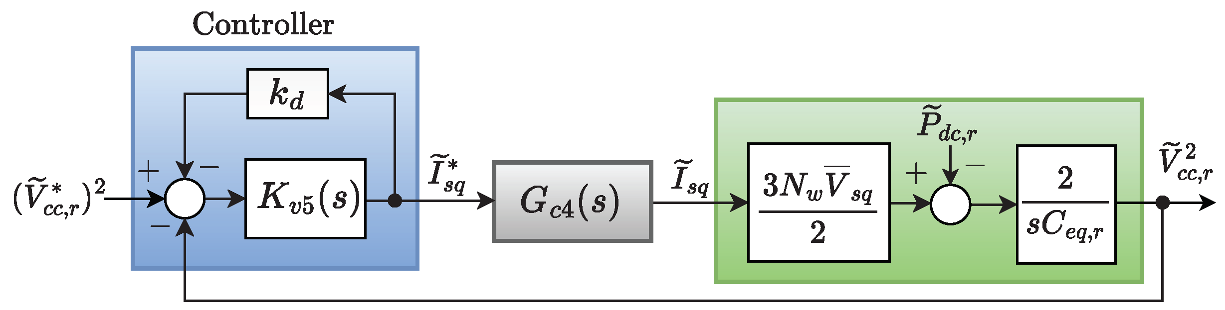
3.2. Control of HVDC-Rectifier DC-Link Voltage with MSC

Once the onshore converter starts to regulate the AC voltage of the PCC during stand-alone operation, some strategy must be implemented to control the HVDC link voltage. Therefore, an external loop turns off the MPPT-OTC algorithm of the MSC of the WECS units and starts to control the energy drained from the WT to regulate the DC link voltage at the offshore converter output terminals. This loop ensures the stable operation of the HVDC system when the load connected to the inverter terminals does not consume all energy converted by the WT. This strategy change occurs when the DC link voltage, measured at the HVDC-rectifier terminals, exceeds its rated value by 10%. Simultaneously, the S o p function enables pitch control, preventing the WT from reaching excessive speeds.
Therefore, neglecting the offshore MMC losses, the following energy balance equation can be written for the offshore MMC:
N w 3 2 v g , q i g , q = P d c , r + C e q 2 d V d c , r 2 d t
where N w ( 3 / 2 ) v g , q i g , q is the power injected into the offshore MMC AC terminals by the WECS units; N w is the total number of WECS units operating in parallel; P d c , r is the power supplied to the HVDC link; ( C e q / 2 ) ( d V d c , r 2 / d t ) is the power absorbed by the capacitor.
Since the MSC and GSC are controlled in current mode, PI-controllers in the d q reference frame can be used to regulate the power injected by the PMSG into the collector network to control the DC link voltage of the offshore converter. Additionally, the droop gain ( k d ) must be added to the controller to enable the parallel operation of several WECS units. The equivalent control block diagram is shown in Figure 14.
Thus, the following closed-loop transfer function can be written:
G v 5 ( s ) = V ˜ d c , r 2 ( s ) V ˜ d c , r * 2 ( s ) = T s k p , v 5 + k i , v 5 s 2 + s T k p , v 5 + k d k i , v 5 1 + k d k p , v 5 + T k i , v 5 1 + k d k p , v 5 ,
where k p , v 5 and k i , v 5 are the proportional and integral gains of the controller of the PI-controller K v 5 , respectively, and T = 3 N w V g / C e q .
Choosing the value of k d , the comparison of Equation (59) with the canonic form of the second-order system allows us to choose the controller gains as:
k p , v 5 = 2 T ζ v 5 ω v 5 k d ω v 5 2 T 2 + k d 2 ω v 5 2 2 T ζ v 5 ω v 5 and k i , v 5 = ω v 5 2 1 + k d k p , v 5 T ,
where ω v 5 and ζ v 5 are the undamped natural frequency and the damping factor of the DC link closed-loop transfer function, respectively.
Although the controllers’ gain depends on the total number of WECS units ( N w ), the obtained answer is not severely impacted if the actual number of units is different from the pre-established value, as discussed in the next section.

3.3. Pitch Angle Control

To control the PMSG speed during stand-alone operation, the pitch control loop of Figure 15 was used. It receives the speed error and generates a pitch reference angle β * for the pitch mechanical system, represented by a first-order transfer function followed by a derivate limiter used to simulate the time response of the real system. The block C β is a PI-controller whose gains were determined empirically.

4. Digital Simulation Results

The system in Figure 1 was implemented and simulated in the PSCAD/EMTDC program to investigate the performance of the proposed strategy. The system dynamic behavior was tested facing three different events: grid disconnection, loss of part of the WECS units, and grid reconnection. The WECS is formed by two equivalent groups, each modeled by an aggregate model representing 30 and 15 smaller units operating in parallel, respectively.
The main parameters of the WT and MMC are given in Table 1 and Table 2, respectively. They were selected based on the methodologies outlined in [40] for wind turbines and in [41,42] for modular multilevel converters. Moreover, the design parameters and gains of voltage and current controllers for the converters of HVDC and WECS units, in both grid-connected and stand-alone operation modes, are presented in Table 3, Table 4 and Table 5, respectively. The controller gains were calculated using the equations given in Section 2 and Section 3 to guarantee the minimum settling time and limit the maximum overshoot for the closed-loop transfer functions of voltages and currents [43] during transitions between operating modes.

4.1. Case 1: Grid Disconnection

Initially, the system operates in grid-connected mode, and the MPPT algorithm controls the WEC units to extract the maximum available power from the wind turbines. At the same time, the onshore MMC injects generated energy into the AC power grid. The load power is equal to 110.7 MVA 105 M W + ȷ 45 Mvar .
However, at t = 1.5 s , a critical event occurs in the AC power system and the main switch in Figure 1 opens, disconnecting the HVDC system from the mains. Following this disconnection, the stand-alone control block comes into action and initiates the onshore MMC voltage regulation process at the point of common coupling (PCC). The control block ensures that the PCC voltage is maintained within specified limits, ensuring the power supply to the local load.
In Figure 16, the waveforms of the dc voltages at the MMC rectifier and inverter terminals are depicted. As the local load does not entirely consume all the power generated by the WECS units, both voltage values begin to increase. This rise in voltage continues until the rectifier dc voltage reaches 352 k V at t = 1.64 s , corresponding to 110% of its nominal value.
Upon reaching this critical voltage threshold, the MPPT controller undergoes a transition. It ceases to extract the maximum power from the PMSG and reduces power injection into the HVDC system, regulating its dc voltage. This control action ensures that the dc voltage remains within safe operating limits, preventing potential over-voltage issues in the HVDC system.
The PCC three-phase voltages and onshore MMC synthesized currents during grid-connected to stand-alone switching modes are shown in Figure 17a and Figure 17b, respectively. Between t = 1.5 s and t = 1.52 s , the grid disconnection is not detected and the AC voltage control of the onshore MMC is not active. As the MPPT strategy remains active, injecting more power than the load consumes, the amplitude of the PCC voltage increases. The currents show a significant harmonic distortion once the voltage reference used in the current control loop is not imposed by the grid any more. Then, at t = 1.52 s , the onshore MMC AC voltage control loop is enabled to regulate the PCC voltages back to their nominal values. Furthermore, the harmonic content of the currents is quickly suppressed.
The distorted waveforms, after disconnection from the grid and before the MMC starts regulating the PCC voltage, can be improved by using a technique that employs two second-order generalized integrators (SOGI) and two notch filters. The SOGIs and notch filters are used to extract, respectively, the positive and negative sequence components of the instantaneous voltages and currents in the PCC, ensuring that the MMC synthesizes balanced currents at its terminals [44].
Figure 18 shows the offshore voltage waveforms of the AC collector network during the transition from a grid-connected to stand-alone mode of operation. Notably, the offshore converter controller effectively regulates the collector AC voltage, irrespective of the operating mode of the onshore MMC converter. This behavior ensures a stable and reliable offshore AC collector network, even during the critical phase of switching between grid-connected and stand-alone modes of the onshore HVDC converter.
Figure 19 shows the three-phase currents of both WECS units. Initially, the generators operate under the control of the MPPT strategy, resulting in a peak current injection of approximately 1.3 k A into the offshore MSC terminals. However, at t = 1.64 s , when the rectifier dc voltage V d c , r reaches 352 k V , the PMSG controller is altered, and the dc voltage control loops are activated. Consequently, the synthesized currents are adjusted to match the specific load requirements during stand-alone operation, decreasing current values. Throughout the stand-alone operation, the synthesized currents of each generator exhibit slightly different peak values. These variations are attributed to the distinct droop gains adopted for each unit, which influence the generators’ current response and control behavior.
Figure 20a,b show the behavior of the rotational speeds of the two groups of generators and the pitch angle of the wind turbines, respectively. The wind speed at the first gensets’ turbines is 11.7 m / s , whereas the wind speed at the second gensets’ turbines is 11 m / s . During grid-connected operation mode, ω g 1 is 15.707 rad / s while ω g 2 is approximately 14.625 rad / s . The pitch angle of both groups of gensets’ turbines is 0 . After the grid disconnection, at t = 1.5 s , both groups of WEC units start to regulate the onshore HVDC DC link voltage. Since the MPPT-OTC algorithm stops working, the pitch controllers vary the angles β 1 and β 2 regulating the rotational speeds of the gensets to restore the power balance between the WT and the PMSG. The delay in the control action seen in β 2 (Figure 20b) is due to the lower wind speed that reaches the second group of WTs.

4.2. Case 2: Loss of WECS Units

The system performance was also tested against the loss of one third of the WECS units. In this case, the simulation starts with the HVDC system already disconnected from the mains. At t = 1.2 s , the second group of 15 WECS is disconnected from the collector network.
Figure 21 shows the behavior of the MMC dc voltages. The instantaneous reduction in the electric power delivered by the wind system is implicated in the sag suffered by the MMC dc voltages once part of the energy stored in the submarine cables and in the SM of the converters is used to supply the load demand. However, the MSC of the remaining unit quickly regulates the power injection into the HVDC link, forcing the offshore MMC dc voltage back to its rated value. This result demonstrates that the difference between the actual number of operating units and the expected number of total units ( N w ) does not affect the performance of the DC link voltage control loop.
Figure 22 depicts the behavior of the unit 1 PMSG three-phase current. Due to the loss of the second group, the remaining PMSG must inject more power into the system, implying an increase in its currents.
The onshore and offshore AC voltages, as shown in Figure 23, are not affected by the disconnection of the units.

4.3. Case 3: Grid Reconnection

In order to reconnect the HVDC system with the grid, the voltage resynchronization strategy proposed in [45] was implemented. The system was considered to operate in the stand-alone mode, where, at t = 0.2 s , the grid voltage is recovered and resynchronization starts. The reconnection with the grid occurs when the phase angle between the PCC and grid voltages is smaller than 0.05 rad, which happens at t = 1.34 s .
Figure 24 shows the waveforms of the PCC and grid voltages. Initially, the PCC voltage leads the grid voltage but, as the resynchronization process evolves, the lagging between them is reduced.
At t = 1.34 s , the resynchronization is completed and the main switch in Figure 1 is closed. At this moment, a signal is sent to the WECS MSC to disable the PMSG dc voltage control loop, enabling the MPPT-OTC algorithm again. Simultaneously, the onshore MMC AC voltage loop is disabled and the converter starts to regulate the HVDC system dc voltage.
Figure 25 shows the MMC dc voltages during the reconnection. Initially, the offshore MMC voltage is equal to the rated value once the system operates in the stand-alone mode. After the grid reconnection, the voltages present a small overshoot due to the control modes switching but are quickly regulated by the control action. Once the onshore converter takes over dc voltage control again, its voltage returns to the nominal value. Due to the power flow between the two converters, the offshore converter voltage is slightly higher.
Figure 26 shows the PMSG three-phase currents during the grid reconnection. Before t = 1.34 s , the system operates in stand-alone mode and the WECS units only produce the amount of energy demanded by the local load. After t = 1.34 s , the onshore MMC is reconnected to the power grid, allowing the WECS units to resume MPPT operation. This reconnection leads to an increase in the value of the currents synthesized by the MMC as the WECS units optimize their power generation to extract the maximum available energy from the WT.

5. Conclusions

This paper proposed an algorithm for controlling an MMC-HVDC system that integrates an offshore wind farm into the AC power system, considering both grid-connected and stand-alone modes of operation. The design steps of the WEC and HVDC controllers are described, encompassing the grid-connected and stand-alone operation of the onshore MMC. During grid-connected operation, the onshore MMC effectively regulates the DC link voltage, while the generating units are controlled to maximize power extraction from the wind turbines. In the event of grid disconnection, the onshore MMC takes over the regulation of the AC voltage at the point of common coupling, ensuring a continuous energy supply to local loads. Simultaneously, the PMSG controller transitions from MPPT operation to regulating the DC link voltage, preventing excessive power injection into the transmission link. Additionally, the turbine pitch angle control system successfully regulates the generator speed.
Linearized mathematical models were developed to derive transfer functions, facilitating the design of the controllers for the entire system. A comprehensive model, including the wind generation units, the HVDC link, and their controllers, was implemented in the PSCAD/EMTDC program. Digital simulation results were presented to validate the performance of the designed controllers, considering both modes of operation for the HVDC link. The modeled system was subjected to three events: the transition between grid-connected and stand-alone modes, the loss of WECS units, and grid reconnection. The onshore MMC AC bus voltage control effectively and quickly regulates the voltages after grid disconnection and maintains stability even after the loss of WECS units. The DC link voltage control system exhibits the desired response, regardless of the disturbance encountered. Furthermore, the pitch control strategy successfully maintains the PMSG speed as stable.
The system’s reconnection with the grid is successfully demonstrated, with a smooth transition back to grid-connected mode. The system efficiently extracts the maximum available power from the wind turbines, maintaining stable dc voltage levels through the HVDC link. Overall, the presented control algorithm and system design demonstrate a reliable performance and robustness in different operating conditions, confirming the effectiveness of the proposed approach for integrating offshore wind farms into the AC power system using MMC-HVDC technology.

Author Contributions

Conceptualization, M.S.P., A.d.O.A., P.M.d.A. and P.G.B.; methodology, M.S.P., A.d.O.A., P.M.d.A. and P.G.B.; investigation, M.S.P., A.d.O.A., P.M.d.A. and P.G.B.; writing—original draft preparation, M.S.P., A.d.O.A. and P.G.B.; writing—review and editing, P.M.d.A. and P.G.B.; visualization, M.S.P., A.d.O.A., P.M.d.A. and P.G.B.; supervision, P.G.B.; funding acquisition, P.G.B. All authors have read and agreed to the published version of the manuscript.

Funding

This study was financed in part by the Coordination for the Improvement of Higher Education Personnel (CAPES)—Finance Code 001, the National Council for Scientific and Technological Development (CNPq)—under grant 306559/2020-0, the State Funding Agency of Minas Gerais (FAPEMIG)—under grant APQ-02050-21, the National Institute for Electric Energy (INERGE), and the Federal University of Juiz de Fora (UFJF).

Acknowledgments

The authors would like to express their gratitute to CAPES, CNPq, FAPEMIG, INERGE, and UFJF.

Conflicts of Interest

The authors declare no conflict of interest.

References

  1. Yaramasu, V.; Wu, B.; Sen, P.C.; Kouro, S.; Narimani, M. High-power wind energy conversion systems: State-of-the-art and emerging technologies. Proc. IEEE 2015, 103, 740–788. [Google Scholar] [CrossRef]
  2. Anaya-Lara, O.; Campos-Gaona, D.; Moreno-Goytia, E.; Adam, G. Offshore Wind Energy Generation: Control, Protection, and Integration to Electrical Systems; John Wiley & Sons: Hoboken, NJ, USA, 2014. [Google Scholar]
  3. Pan, W.; Chang, Y.; Chen, H. Hybrid multi-terminal HVDC system for large scale wind power. In Proceedings of the 2006 IEEE PES Power Systems Conference and Exposition, Atlanta, GA, USA, 29 October–1 November 2006; IEEE: Piscatway, NJ, USA, 2006; pp. 755–759. [Google Scholar]
  4. Andersen, B.R.; Groeman, F.; Alvira, D.; Anaya-Lara, O.; Tang, G.; Hanson, J.; Haeusler, M.; Karoui, K.; Muttik, P.; Nguefeu, S.; et al. Integration of large scale wind generation using HVDC and power electronics. CIGRE Publ. Work. Group B 2009, 4, 2009. [Google Scholar]
  5. Korompili, A.; Wu, Q.; Zhao, H. Review of VSC HVDC connection for offshore wind power integration. Renew. Sustain. Energy Rev. 2016, 59, 1405–1414. [Google Scholar] [CrossRef] [Green Version]
  6. Lesnicar, A.; Marquardt, R. An innovative modular multilevel converter topology suitable for a wide power range. In Proceedings of the 2003 IEEE Bologna Power Tech Conference, Bologna, Italy, 23–26 June 2003; IEEE: Piscatway, NJ, USA, 2003; Volume 3, p. 6. [Google Scholar]
  7. Akagi, H. Classification, terminology, and application of the modular multilevel cascade converter (MMCC). IEEE Trans. Power Electron. 2011, 26, 3119–3130. [Google Scholar] [CrossRef]
  8. Malinowski, M.; Gopakumar, K.; Rodriguez, J.; Pérez, M.A. A survey on cascaded multilevel inverters. IEEE Trans. Ind. Electron. 2010, 57, 2197–2206. [Google Scholar] [CrossRef]
  9. Ludois, D.C.; Venkataramanan, G. Simplified terminal behavioral model for a modular multilevel converter. IEEE Trans. Power Electron. 2014, 29, 1622–1631. [Google Scholar] [CrossRef]
  10. Li, W.; Zhu, M.; Chao, P.; Liang, X.; Xu, D. Enhanced FRT and postfault recovery control for MMC-HVDC connected offshore wind farms. IEEE Trans. Power Syst. 2019, 35, 1606–1617. [Google Scholar] [CrossRef]
  11. Li, Y.; An, T.; Zhang, D.; Pei, X.; Ji, K.; Tang, G. Analysis and suppression control of high frequency resonance for MMC-HVDC system. IEEE Trans. Power Deliv. 2021, 36, 3867–3881. [Google Scholar] [CrossRef]
  12. Wang, Y.; Zhao, C.; Guo, C. Comparison study of small-signal stability of MMC-HVDC system in different control modes. Int. J. Electr. Power Energy Syst. 2019, 111, 425–435. [Google Scholar] [CrossRef]
  13. Shi, X.; Yang, R.; Cai, X.; Fang, Z.; Dong, P.; Rao, F. Improved comprehensive energy-based control for MMC-HVDC system. Int. J. Electr. Power Energy Syst. 2023, 145, 108593. [Google Scholar] [CrossRef]
  14. Belhaouane, M.M.; Ayari, M.; Guillaud, X.; Braiek, N.B. Robust control design of MMC-HVDC systems using multivariable optimal guaranteed cost approach. IEEE Trans. Ind. Appl. 2019, 55, 2952–2963. [Google Scholar] [CrossRef]
  15. Lourenço, L.F.; Perez, F.; Iovine, A.; Damm, G.; Monaro, R.M.; Salles, M.B. Stability Analysis of Grid-Forming MMC-HVDC Transmission Connected to Legacy Power Systems. Energies 2021, 14, 8017. [Google Scholar] [CrossRef]
  16. Dadjo Tavakoli, S.; Prieto-Araujo, E.; Sánchez-Sánchez, E.; Gomis-Bellmunt, O. Interaction assessment and stability analysis of the MMC-based VSC-HVDC link. Energies 2020, 13, 2075. [Google Scholar] [CrossRef] [Green Version]
  17. Chandio, R.H.; Chachar, F.A.; Soomro, J.B.; Ansari, J.A.; Munir, H.M.; Zawbaa, H.M.; Kamel, S. Control and protection of MMC-based HVDC systems: A review. Energy Rep. 2023, 9, 1571–1588. [Google Scholar] [CrossRef]
  18. Zeng, X.; Liu, T.; Wang, S.; Dong, Y.; Li, B.; Chen, Z. Coordinated control of MMC-HVDC system with offshore wind farm for providing emulated inertia support. IET Renew. Power Gener. 2020, 14, 673–683. [Google Scholar] [CrossRef]
  19. Jia, K.; Dong, X.; Wen, Z.; Wu, W.; Bi, T. Harmonic injection based fault ride-through control of mmc-hvdc connected offshore wind farms. IEEE Trans. Sustain. Energy 2023, 14, 1796–1806. [Google Scholar] [CrossRef]
  20. Hossain, M.I.; Abido, M.A. Positive-negative sequence current controller for LVRT improvement of wind farms integrated MMC-HVDC network. IEEE Access 2020, 8, 193314–193339. [Google Scholar] [CrossRef]
  21. Tu, L.; Yang, Y.; Yang, J.; Sun, T. The Synthetic Inertia Controller for MMC-HVDC Based Offshore Wind Farm Integration. In Proceedings of the 2021 IEEE 1st International Power Electronics and Application Symposium (PEAS), Shanghai, China, 13–15 November 2021; IEEE: Pisctaway, NJ, USA, 2021; pp. 1–4. [Google Scholar]
  22. Kazemi Golkhandan, R.; Torkaman, H.; Aghaebrahimi, M.R.; Keyhani, A. Load frequency control of smart isolated power grids with high wind farm penetrations. IET Renew. Power Gener. 2020, 14, 1228–1238. [Google Scholar] [CrossRef]
  23. Kamal, F.; Chowdhury, B. Grid Forming Inverter Control in a Type 4 Wind Turbine for Flexible Power Transfer in an Islanded Microgrid. In Proceedings of the 2021 North American Power Symposium (NAPS), College Station, TX, USA, 14–16 November 2021; IEEE: Pisctaway, NJ, USA, 2021; pp. 1–6. [Google Scholar]
  24. Ullah, K.; Basit, A.; Ullah, Z.; Albogamy, F.R.; Hafeez, G. Automatic generation control in modern power systems with wind power and electric vehicles. Energies 2022, 15, 1771. [Google Scholar] [CrossRef]
  25. Asghar, R.; Riganti Fulginei, F.; Wadood, H.; Saeed, S. A Review of Load Frequency Control Schemes Deployed for Wind-Integrated Power Systems. Sustainability 2023, 15, 8380. [Google Scholar] [CrossRef]
  26. Yuan, X.; Li, Y. Control of variable pitch and variable speed direct-drive wind turbines in weak grid systems with active power balance. IET Renew. Power Gener. 2014, 8, 119–131. [Google Scholar] [CrossRef]
  27. Rodriguez, P.; Teodorescu, R.; Candela, I.; Timbus, A.V.; Liserre, M.; Blaabjerg, F. New positive-sequence voltage detector for grid synchronization of power converters under faulty grid conditions. In Proceedings of the Power Electronics Specialists Conference (PESC), Jeju, Republic of Korea, 18–22 June 2006; IEEE: Piscatway, NJ, USA, 2006; pp. 1–7. [Google Scholar]
  28. Tu, Q.; Xu, Z.; Zhang, J. Circulating current suppressing controller in modular multilevel converter. In Proceedings of the IECON 2010—36th Annual Conference on IEEE Industrial Electronics Society, Glendale, AZ, USA, 7–10 November 2010; IEEE: Piscatway, NJ, USA, 2010; pp. 3198–3202. [Google Scholar]
  29. Duarte, S.N.; Barbosa, P.G.; Kabalcı, E. Chapter 8—STATCOM and DSTATCOM with modular multilevel converters. In Multilevel Inverters; Kabalcı, E., Ed.; Academic Press: Cambridge, MA, USA, 2021; pp. 209–248. [Google Scholar] [CrossRef]
  30. Sharifabadi, K.; Harnefors, L.; Nee, H.P.; Norrga, S.; Teodorescu, R. Design, Control, and Application of Modular Multilevel Converters for HVDC Transmission Systems; John Wiley & Sons: Hoboken, NJ, USA, 2016. [Google Scholar]
  31. Yazdani, A.; Iravani, R. Voltage-Sourced Converters in Power Systems; John Wiley & Sons: Hoboken, NJ, USA, 2010. [Google Scholar]
  32. Duarte, S.N.; Almeida, P.M.; Barbosa, P.G. Voltage regulation of a remote microgrid bus with a modular multilevel STATCOM. Electr. Power Syst. Res. 2022, 212, 108299. [Google Scholar] [CrossRef]
  33. Duarte, S.N.; Ghetti, F.T.; de Almeida, P.M.; Barbosa, P.G. Zero-sequence voltage compensation of a distribution network through a four-wire modular multilevel static synchronous compensator. Int. J. Electr. Power Energy Syst. 2019, 109, 57–72. [Google Scholar] [CrossRef]
  34. Almeida, A.d.O.; Ghetti, F.T.; Ribeiro, A.S.B.; de Almeida, P.M.; Barbosa, P.G. Circulating currents suppression strategies for modular multilevel converter. In Proceedings of the 2017 Brazilian Power Electronics Conference (COBEP), Juiz de Fora, Brazil, 19–22 November 2017; pp. 1–5. [Google Scholar] [CrossRef]
  35. Duarte, S.N.; Almeida, P.M.; Barbosa, P.G. Voltage compensation in multi-grounded distribution network with a three-phase five-wire DSTATCOM. Electr. Power Syst. Res. 2021, 197, 107310. [Google Scholar] [CrossRef]
  36. Paulo, M.S. Coordinated Control of an Offshore Wind Farm Considering an MMC-HVDC Transmission System Operating in On-Grid and Off-Grid Modes. Master’s Thesis, Federal University of Juiz de Fora, Juiz de Fora, Brazil, 2023. (In Portuguese). [Google Scholar]
  37. Wu, B.; Lang, Y.; Zargari, N.; Kouro, S. Power Conversion and Control of Wind Energy Systems; John Wiley & Sons: Hoboken, NJ, USA, 2011; Volume 76. [Google Scholar]
  38. Almeida, A.O.; Tomim, M.A.; Almeida, P.M.; Barbosa, P.G. A control strategy for an offshore wind farm with the generating units connected in series with a VSC-HVDC transmission link. Electr. Power Syst. Res. 2020, 180, 106121. [Google Scholar] [CrossRef]
  39. Almeida, A.O.; Almeida, P.M.; Barbosa, P.G. Design Methodology for the DC Link Current Controller of a Series-Connected Offshore Wind Farm. In Proceedings of the 2022 14th Seminar on Power Electronics and Control (SEPOC), Santa Maria, Brazil, 12–15 November 2022; IEEE: Piscataway, NJ, USA, 2022; pp. 1–6. [Google Scholar]
  40. Jonkman, J.; Butterfield, S.; Musial, W.; Scott, G. Definition of a 5-MW Reference Wind Turbine for Offshore System Development; Technical Report; National Renewable Energy Lab. (NREL): Golden, CO, USA, 2009. [Google Scholar] [CrossRef] [Green Version]
  41. Xu, J.; Zhao, C.; Xiong, Y.; Li, C.; Ji, Y.; An, T. Optimal Design of MMC Levels for Electromagnetic Transient Studies of MMC-HVDC. IEEE Trans. Power Deliv. 2016, 31, 1663–1672. [Google Scholar] [CrossRef]
  42. Xu, Z.; Xiao, H.; Zhang, Z. Selection methods of main circuit parameters for modular multilevel converters. IET Renew. Power Gener. 2016, 10, 788–797. [Google Scholar] [CrossRef]
  43. Ogata, K. Modern Control Engineering, 5th ed.; Prentice Hall: Hoboken, NJ, USA, 2010. [Google Scholar]
  44. Duarte, S.N.; Souza, B.C.; Almeida, P.M.; Araujo, L.R.; Barbosa, P.G. Control algorithm for DSTATCOM to compensate consumer-generated negative and zero sequence voltage unbalance. Int. J. Electr. Power Energy Syst. 2020, 120, 105957. [Google Scholar] [CrossRef]
  45. Ochs, D.S.; Mirafzal, B.; Sotoodeh, P. A Method of Seamless Transitions Between Grid-Tied and Stand-Alone Modes of Operation for Utility-Interactive Three-Phase Inverters. IEEE Trans. Ind. Appl. 2014, 50, 1934–1941. [Google Scholar] [CrossRef]
Figure 1. Simplified diagram of a VSC–HVDC system used to integrate an offshore wind farm.
Energies 16 05891 g001
Figure 2. Block diagram of the onshore MMC control strategy for grid-connected operation.
Energies 16 05891 g002
Figure 3. Block diagram of the onshore MMC current control.
Energies 16 05891 g003
Figure 4. MMC dc-voltage control loop for grid-connected operation.
Energies 16 05891 g004
Figure 5. Decoupled circulating current control loops.
Energies 16 05891 g005
Figure 6. Block diagram of the offshore MMC control strategy.
Energies 16 05891 g006
Figure 7. Block diagram of the offshore MMC AC bus voltage control.
Energies 16 05891 g007
Figure 8. Decoupled block diagram of the offshore MMC AC bus voltage control.
Energies 16 05891 g008
Figure 9. Control block diagram for the GSC.
Energies 16 05891 g009
Figure 10. Simplified control block diagram for MSC for grid-connected operation.
Energies 16 05891 g010
Figure 11. Block diagram of the PMSG current control.
Energies 16 05891 g011
Figure 12. Complete block diagram of the onshore MMC control strategy considering grid-connected and stand-alone operation modes.
Energies 16 05891 g012
Figure 13. MMC decoupled AC voltage control loops used to regulate the PCC voltage during the stand-alone operation.
Energies 16 05891 g013
Figure 14. Stand-alone DC link voltage control loop.
Energies 16 05891 g014
Figure 15. Block diagram of the pitch angle control loop.
Energies 16 05891 g015
Figure 16. Onshore and offshore MMC DC link voltages during grid-connected to stand-alone switching modes.
Energies 16 05891 g016
Figure 17. Detailed onshore MMC waveforms during grid-connected to stand-alone switching modes: (a) PCC three-phase voltages and (b) synthesized three-phase currents.
Energies 16 05891 g017
Figure 18. Detailed offshore collector network voltage during grid-connected to stand-alone switching modes.
Energies 16 05891 g018
Figure 19. Detailed PMSG currents during grid-connected to stand-alone switching modes: (a) 1st unit and (b) 2nd unit.
Energies 16 05891 g019
Figure 20. WECS variables: (a) PMSG speed and (b) pitch angle.
Energies 16 05891 g020
Figure 21. Onshore and offshore MMC DC link voltages during the loss of WECS units.
Energies 16 05891 g021
Figure 22. Detailed PMSG currents during the loss of WECS units.
Energies 16 05891 g022
Figure 23. Onshore and offshore AC voltages waveforms during the loss of WECS units: (a) Onshore and (b) Offshore.
Energies 16 05891 g023
Figure 24. PCC and grid voltages during the voltage resynchronization.
Energies 16 05891 g024
Figure 25. MMC onshore and offshore DC link voltages during the grid reconnection.
Energies 16 05891 g025
Figure 26. Details of PMSG currents during the grid reconnection.
Energies 16 05891 g026
Table 1. WECS main parameters.
ParameterValue
PMSG rated power M W
PMSG rms voltage k V
PMSG frequency20  Hz
PMSG resistance9.35  m Ω
PMSG inductance2.2  m H
B2B rated dc voltage10  k V
B2B switching frequency2.4  k Hz
B2B transformer turns ratio3:33
B2B filter resistance m Ω
B2B filter inductance m H
Gearbox ratio10:1
Number of units of the 1st equivalent group30
Number of units of the 2nd equivalent group15
Table 2. HVDC system main parameters.
ParameterValue
MMC dc voltage320  k V
Offshore MMC AC voltage138  k V
Onshore MMC AC voltage138  k V
Number of SM per arm18
SM capacitance900  μ F
Arm resistance0.25  Ω
Arm inductance10.5  m H
MMC switching frequency1.26  k Hz
AC grid voltage500  k V
AC grid frequency60  Hz
Offshore transformer turns ratio138:33
Onshore transformer turns ratio138:500
AC onshore MMC filter resistance0.25  Ω
AC onshore MMC filter inductance12.8  m H
AC onshore MMC filter capacitance10  μ F
DC submarine cable length50  k m
Table 3. MSC voltage controller.
WECS GroupParameterValue
1stUndamped natural frequency ( ω v 3 )20   rad / s
Damping factor ( ζ v 3 )1
Proportional gain ( k p , v 3 ) 2.96 × 10 5 A / V
Integral gain ( k i , v 3 ) 2.96 × 10 4 A / V s
Droop gain ( k d )9.6 A / V
2ndUndamped natural frequency ( ω v 3 )20   rad / s
Damping factor ( ζ v 3 )1
Proportional gain ( k p , v 3 ) 2.963 × 10 5 A / V
Integral gain ( k i , v 3 ) 2.96 × 10 4 A / V s
Droop gain ( k d , v 3 )3.2 A / V
Table 4. HVDC current controllers.
SideParameterValue
Offshore MMCUndamped natural frequency ( ω c 2 )2000   rad / s
Damping factor ( ζ c 2 )0.7
Proportional gain ( k p , c 2 )50.2 V / A
Integral gain ( k i , c 2 )7142.8 V / A s
Onshore MMCUndamped natural frequency ( ω c 1 )2000   rad / s
Damping factor ( ζ c 1 )0.7
Proportional gain ( k p , c 1 )50.2 V / A
Integral gain ( k i , c 1 )7142.8 V / A s
Table 5. Onshore MMC voltage controllers.
SideParameterValue
DC link
(grid-connected)
Undamped natural frequency ( ω v 1 )20   rad / s
Damping factor ( ζ v 1 )2
Proportional gain ( k p , v 1 ) 1.2 × 10 4 A / V
Integral gain ( k i , v 1 ) 5.9 × 10 4 A / V s
AC bus
(stand-alone)
Undamped natural frequency ( ω v 2 )20   rad / s
Damping factor ( ζ v 2 )2
Proportional gain ( k p , v 2 )0.0008 A / V
Integral gain ( k i , v 2 )0.004 A / V s
Disclaimer/Publisher’s Note: The statements, opinions and data contained in all publications are solely those of the individual author(s) and contributor(s) and not of MDPI and/or the editor(s). MDPI and/or the editor(s) disclaim responsibility for any injury to people or property resulting from any ideas, methods, instructions or products referred to in the content.

