Article

The Impact of Bend–Twist Coupling on Structural Characteristics and Flutter Limit of Ultra-Long Flexible Wind Turbine Composite Blades

State Key Laboratory for Alternate Electrical Power System with Renewable Energy Sources, North China Electric Power University, Beijing 102206, China
*
Author to whom correspondence should be addressed.
Energies 2023, 16(15), 5829; https://doi.org/10.3390/en16155829
Submission received: 23 June 2023 / Revised: 27 July 2023 / Accepted: 3 August 2023 / Published: 6 August 2023
(This article belongs to the Special Issue Wind Turbine 2023)

Abstract

:
Flutter is an instability phenomenon that can occur in wind turbine blades due to fluid–structure interaction, particularly for longer and more flexible blades. Aeroelastic tailoring through bend–twist coupling is an effective method to enhance the aeroelastic performance of blades. In this study, we investigate the impact of bend–twist coupling on the structural performance and flutter limit of the IEA 15 MW blade, which is currently the longest reference wind turbine blade, and determine the optimal layup configuration that maximizes the flutter speed. The blade is modeled by NuMAD and iVABS, and the cross-section properties are obtained by PreComb and VABS. The accuracy of the blade model is verified in terms of stiffness and frequency. The bend–twist coupling is implemented by changing the fiber angle of the skin and spar cap considering symmetric and asymmetric layups. The flutter limits of both the baseline and the bend–twist coupled blade are evaluated based on HAWC2. The results show that the angle of spar cap carbon fiber has a greater effect on the blade’s structural properties and flutter speed than the skin fiber. Varying the spar cap carbon fiber angle increases the flutter speed, with the effect being more significant for the symmetric layup, up to 9.66% at a fiber angle of 25 degrees. In contrast, the variation in skin fiber angle has a relatively small impact on flutter speed—within ±3%.

1. Introduction

The wind industry is rapidly developing, and the Global Wind Energy Council (GWEC) estimates that the average turbine rating for new installations will exceed 12 MW in 2025 [1]. The blade is a critical component for capturing wind energy, mainly constructed of composite fiber to meet rigidity requirements while minimizing weight [2,3,4]. However, to break the square–cube law, the mass and stiffness of the blade are compressed, resulting in greater flexibility that puts the blade at risk of flutter during operation. The Science report [5] emphasized the need for stability analysis of ultra-long flexible blades to ensure safety margins for flutter. Utilizing bend–twist coupling (BTC) for aeroelastic tailoring is a proven technique to enhance the aeroelastic performance of blades. However, this can also alter the blade’s structural properties, such as flapwise and torsional stiffness, which can affect the flutter limit of the blade [6,7,8].
Bent–twist coupled blades have been widely studied as passive load reduction methods. Veers [9] and Lobitz [10,11], of Sandia National Laboratory, were the first to investigate blade load reduction by BTC, and they found that BTC leads to a slight decrease in annual power production, but the fatigue load on the blade can be reduced substantially. Bottasso [12] conducted a parametric study of bent–twist coupled blades for 2 MW wind turbines by changing the angle of the skin and spar cap fibers to introduce BTC in both full and partial blade areas. The results show that changing the fiber orientation in the radial part of the blade can design blades with significant load reduction capability while being lighter than the baseline uncoupled blades. Bagherpour [13] demonstrated the potential of the material BTC method to reduce blade load and found that by changing the off-axis fiber angle of the spar cap of the DTU 10 MW blade, the blade root bending fatigue and ultimate load could be reduced by 10% and 8%, respectively. Meng [14] investigated the effect of introducing BTC by changing the spar cap fiber orientation on the structural properties and fatigue life of NREL 5 MW blades, and the results showed that there was a substantial decrease in flapwise mode frequency and a slight increase in torsional mode frequency, and the bend–twist coupled blades could reduce the fatigue load in the wake condition. Chen [15] obtained the cross-sectional stiffness of the NREL 5 MW BTC adaptive blade by VABS [16] and investigated its relationship with the off-axis fiber angle of the spar cap, and evaluated the load reduction effect under wind shear inflow conditions. The results showed that the tension and flapwise stiffness decreased significantly with increasing fiber angle, while the edgewise stiffness was less affected and the torsional stiffness increased.
The BTC will cause the blade to undergo certain torsion in bending, which changes the aerodynamic performance and, thus, affects the flutter limit. The linear frequency domain analysis method to predict the flutter limit has the advantage of short computation time and the ability to find the cause of blade instability quickly. Lobitz [17] found that BTC changes the damping coefficient of the first-order torsional mode of the flutter mode. The flutter speed will decrease when the blade BTC towards feather and increase when the blade BTC towards stall. Stäblein [18] used the linearization tool HAWCStab2 to investigate the effect of material coupling on the aeroelastic mode and stability limits of the DTU 10 MW RWT. The results showed that the edge-twist coupling towards feather caused a decrease in the blade instability limit, but it was not possible to investigate the effect of flap-twist coupling on the classical flutter because the blade first-order edgewise mode was already unstable before reaching the flutter speed. Shakya [19] calculated the blade cross-sectional stiffness for various combinations of skin triaxial fiber angles by PreComp [20]. Then, they used a parametric approach to investigate the effect of the fiber angle of the symmetric or asymmetric skin of the NREL 5 MW and SNL 61.5 wind turbine blades on the flutter speed. It was shown that the full-blade asymmetric skin can increase the flutter speed by 100% at the appropriate angle.
The time domain analysis method can take into account the nonlinearity and maintain the accuracy of the calculation results. The commonly used time-domain aeroelastic tools are OpenFAST [21], HAWC2 [22], and Bladed [23]. In another study by Shakya [24], they performed a detailed parametric study exploring the effect of skin unbalance on flutter limit in different regions of SNL 61.5 blade by the time-domain analysis method considering geometric nonlinearity. The results indicated that the asymmetric skin exhibited higher critical flutter speed than the symmetric skin and the maximum flutter speed obtained from the nonlinear analysis was lower than that obtained from the linear analysis. Hayat [25] investigated the flutter limit of the NREL 5 MW blade with an unbalanced fiber angle, material, and thickness of the skin. The flutter speed was found to be reduced by 5% with unbalanced layup angles and increased by about 7.6–9.5% with the use of carbon fibers to replace the glass fiber generating material and thickness unbalanced fibers. Zhou [26] combined the nonlinear beam model with the BEM method and the non-constant dynamic stall model to investigate the flutter limit when the NREL 5 MW blade skin fiber angle and thickness are unbalanced. The results show that the unbalanced skin laminate has no significant effect on the flutter limit in the nonlinear flutter analysis. Torregrosa [27] found that the flutter wind speed can be increased by 10% when changing the spar cap fiber of the NREL Phase VI wind turbine blade from 0 degrees to 8 degrees. However, the above-mentioned research objects are mostly focused on wind turbine blades with a capacity below 10 MW and blade length shorter than 100 m.
The IEA 15 MW reference wind turbine (RWT) is currently the largest and most technologically advanced RWT [28]. Many researchers have conducted extensive studies on the IEA 15 MW wind turbine to better understand its aeroelastic behavior and to develop new technologies and design strategies to enhance its performance and efficiency. Rinker [29] compared the aeroelastic response of the IEA 15 MW RWT under steady wind, step wind, and turbulent wind conditions from HAWC2 and OpenFAST. Fritz [30] presented an extension model of blade element momentum theory for swept blades, and it was validated using the IEA 15 MW RWT blade. Scott [31] utilized two optimization strategies, with the objectives of minimizing the mass and leveling the cost of energy, respectively, to optimize the design of the IEA 15 MW RWT blade. Trigaux [32] investigated the aeroelastic effects on the IEA 15 MW RWT in a turbulent atmospheric boundary layer. The results demonstrated that the blades undergo substantial displacements, causing significant changes in loads along the blade span. The turbulence also interacts with the natural frequencies of the blades, resulting in variations in the spectra of the different loads. Oliveira [33] conducted full-scale CFD simulations of the IEA 15 MW wind turbine to evaluate its performance. Loubeyres [34] investigated stall flutter instabilities on the IEA-15 reference wind turbine under idling conditions. The results showed that the blades experienced large amplitude vibrations in the parked state and under specific strong crosswind conditions. To the authors’ knowledge, the effect of BTC on the structural properties and flutter limits of ultra-large wind turbine blades has not been studied in detail.
This paper performs a detailed parametric study of the IEA 15 MW RWT blade to investigate the effects of symmetric and asymmetric skins and spar cap carbon fiber angles on the structural properties and flutter limits. The IEA 15 MW RWT blade is modeled using iVABS [35] and NuMAD [36], respectively, and its accuracy is verified by solving the blade section mass and stiffness matrices by VABS version 4.0 and PreComb version 1.00.03 software. The BTC blade designs are achieved by varying the fiber angles, and their impacts on the structural properties of the blades are evaluated. The flutter speed is obtained by simulating the time-series aeroelastic response of the wind turbine for runaway situations based on the HAWC2. The optimal layup regions and angles for increasing the flutter speed are identified, thereby providing a valuable reference for the anti-flutter design of ultra-long flexible blades.

2. Aeroelastic Model

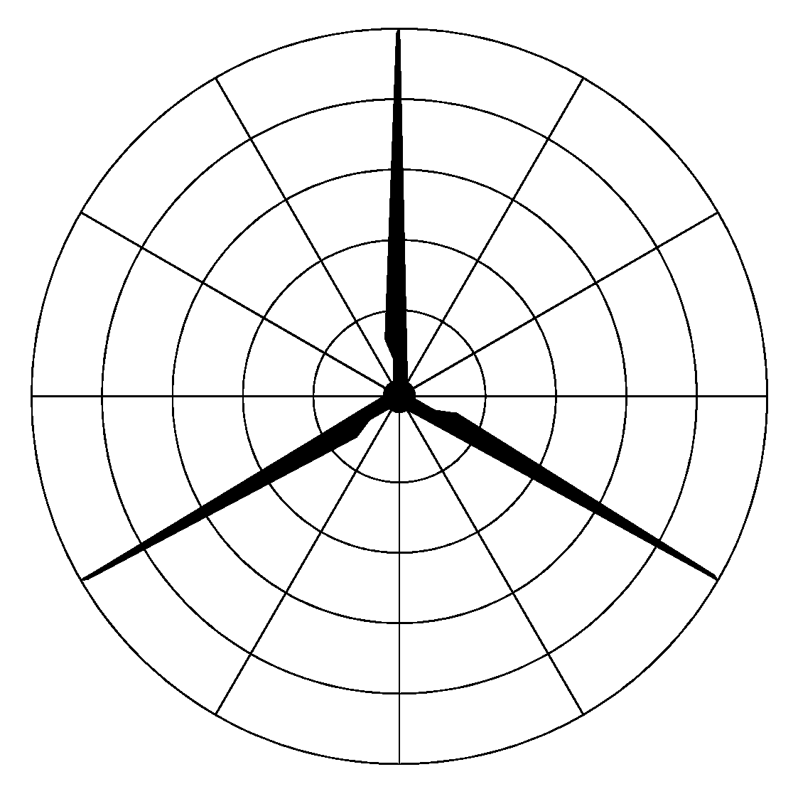
2.1. Polar Grid Blade Element Momentum Model

The classical blade element momentum (BEM) is widely used in the wind energy industry because of its simple and fast calculation, but with the enormous growth of wind turbine size, its assumption of uniform in-plane loading may cause large errors in blade aerodynamic loading. The basic idea of the polar grid BEM theory is to calculate the thrust and torque coefficient of each blade separately, and the thrust and torque coefficients of the grid points not on the blade are obtained by weighting the azimuth between the grid points and the two adjacent blades [37]. The schematic diagram is shown in Figure 1.
The specific calculation procedure of the polar grid BEM model is as follows:
The relationship between the thrust coefficient and the axial induction factor is fitted with a polynomial and expressed as:
a = 0.0883 C T 3 + 0.0586 C T 2 + 0.2460 C T
The local induction factor is defined as:
a = | U i | | U 0 , l |
where U i is local induction velocity and U 0 , l is local free wind speed.
The relative wind speed vector of the blade cross-section U b S is
U b S = T G S ( U 0 G + U i G x ˙ b G )
where S is the cross-sectional co-ordinate system, G is the global co-ordinate system, b is the number of adjacent blades, T G S is the transformation matrix of the global co-ordinate system into the cross-sectional co-ordinate system, U 0 G is the free wind speed, U i G is the induced wind speed, and x ˙ b G is the blade rotation speed.
The angle of attack α b and the relative wind speed U r , b can be expressed as
α b = arctan | U b , y S | | U b , x S | θ
U r , b = U b , x S 2 + U b , y S 2
where θ is the pitch angle and U b , x S and U b , y S are components of the relative wind speed vector in the x and y directions, respectively.
According to the BEM theory, the thrust d T b and the moment d Q b are
d T b = 1 2 ρ U r , b 2 C n , b ( α b ) c d r
d Q b = 1 2 ρ U r , b 2 C t , b ( α b ) c d r
C n , b ( α b ) = C L cos ϕ + C D sin ϕ
C t , b ( α b ) = C L sin ϕ C D cos ϕ
where C L and C D are the lift coefficient and drag coefficient, respectively.
The thrust and torque coefficients for the points on the blades are expressed as
C T , b = d T b ρ π U 0 2 r 2 d r
C Q , b = d Q b ρ π U 0 2 r 2 d r
The thrust and torque coefficients at any point (azimuthal angle of ϕ ) are expressed as
C T / Q = C T / Q , 1 + ( ϕ ϕ 1 ) ( C T / Q , 2 C T / Q , 1 ) ϕ 2 ϕ 1
The Prandtl blade tip loss correction factor F [38] was introduced due to the blade tip loss effect caused by the limited number of blades. Dynamic stall is a strong nonlinear non-constant aerodynamic effect, and this phenomenon is important for flutter analysis and accurate calculation of the critical flutter speed [39]. Therefore, a modified Beddoes-Leishman model [40] is used to describe the non-constant aerodynamic forces on the airfoil under stall flow with the attached flow and trailing edge separation.

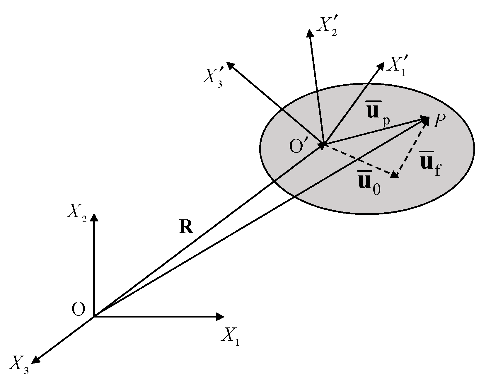
2.2. Structural Model

The single classical linear Timoshenko or Bernoulli–Euler beam model cannot capture the nonlinear behavior of large wind turbine blades [41]. The structural model of wind turbines in HAWC2 is based on a multibody formulation, which discretizes the blade into multiple Timoshenko beam elements, and structural nonlinear effects such as large rotations and translations can be captured [41]. Figure 2 shows the schematic diagram of the co-ordinate system in HAWC2.
The position of a point on the flexible body is expressed as
r p = R + A u ¯ p = R + A ( u ¯ 0 + u ¯ f ) = R + A u ¯ 0 + A S q f
where R is the vector from the origin of the inertial co-ordinate system to the origin of the floating co-ordinate system, A is the rotational transformation matrix from the floating co-ordinate system to the inertial co-ordinate system, and u ¯ p is the position vector of the point in the floating co-ordinate system, which is the sum of the position of material point of the undeformed flexible body u ¯ 0 and deflection of material point of the deformed flexible body u ¯ f . And u ¯ f can be expressed by the shape function S and the vector of degrees of freedom q f .
The velocity of this point can be expressed as
r ˙ p = R ˙ + A ˙ u ¯ p + A S q ˙ f = R ˙ + A ( ω ¯ × u ¯ p ) + A S q ˙ f
The above formula can be illustrated in a matrix form as follows:
r ˙ p = [ I   A ( u ¯ p × I ) A S ] [ R ˙ ω ¯ q ˙ f ] = H q ˙
where I is the identity matrix, H = [ I   A ( u ¯ p × I ) A S ] and q ˙ is the generalized velocity vector.
The acceleration at this point can be expressed as
r ¨ p = H ˙ q ˙ + H q ¨ = [ I   A ( u ¯ p × I ) A S ] [ R ¨ ω ¯ ˙ q ¨ f ] + A [ ω ¯ × ( ω ¯ × u ¯ p ) + 2 ω ¯ × u ¯ ˙ p ]
For anisotropic beam elements, the shape function S is expressed as
S = T E S N T N Z T E S 4 T
where
T E S 4 T = [ T E S T T E S T T E S T T E S T ]
T E S is the standard orthogonal transformation matrix from the element co-ordinate system to the floating co-ordinate system, N T is the rotation matrix of the points not on the centerline, and N Z is the offset and rotation matrix of the centerline.
The virtual work is given as follows:
δ W = V δ r ρ r ¨ d V = V H δ q ρ r ¨ d V
The virtual displacement is obtained from Equation (13) and is expressed as
δ r = δ R + δ A u ¯ 0 + A S δ q f = [ I   A ( u ¯ p × I ) A S ] [ δ R δ θ δ q f ] = H δ q
Substituting Equations (16) and (20) into Equation (19) yields
δ W = V δ q T [ I ( u ¯ p × I ) T A T S T A T ] ρ { [ I   A ( u ¯ p × I ) A S ] [ R ¨ ω ¯ ˙ q ¨ f ] + A [ ω ¯ × ( ω ¯ × u ¯ p ) + 2 ω ¯ × u ¯ ˙ p ] } d V = δ q T ( M [ R ¨ ω ¯ ˙ q ¨ f ] + Q )
where M and Q are the mass matrix and load vector, respectively. They can be denoted as
M = V ρ [ I A ( u ¯ p × I ) A S A ( u ¯ p × I ) ( u ¯ p × I ) T ( u ¯ p × I ) ( u ¯ p × I ) T S A S ( u ¯ p × I ) T S S T S ] d V
Q = V ρ [ A [ ω ¯ × ( ω ¯ × u ¯ p ) + 2 ω ¯ × u ¯ ˙ p ] ( u ¯ p × I ) T [ ω ¯ × ( ω ¯ × u ¯ p ) + 2 ω ¯ × u ¯ ˙ p ] S T [ ω ¯ × ( ω ¯ × u ¯ p ) + 2 ω ¯ × u ¯ ˙ p ] ] d V

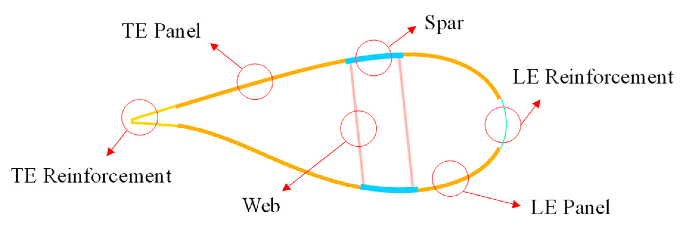
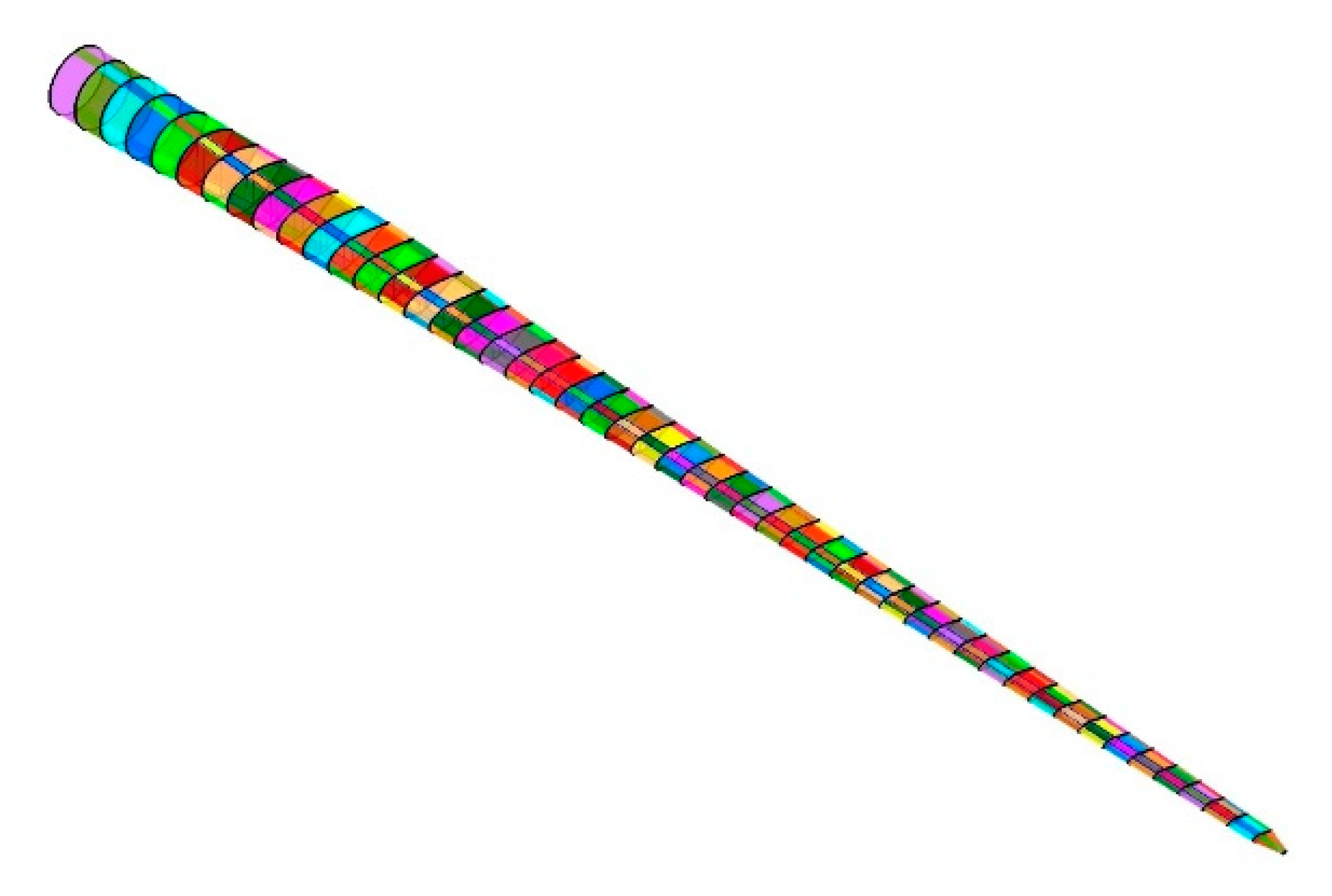
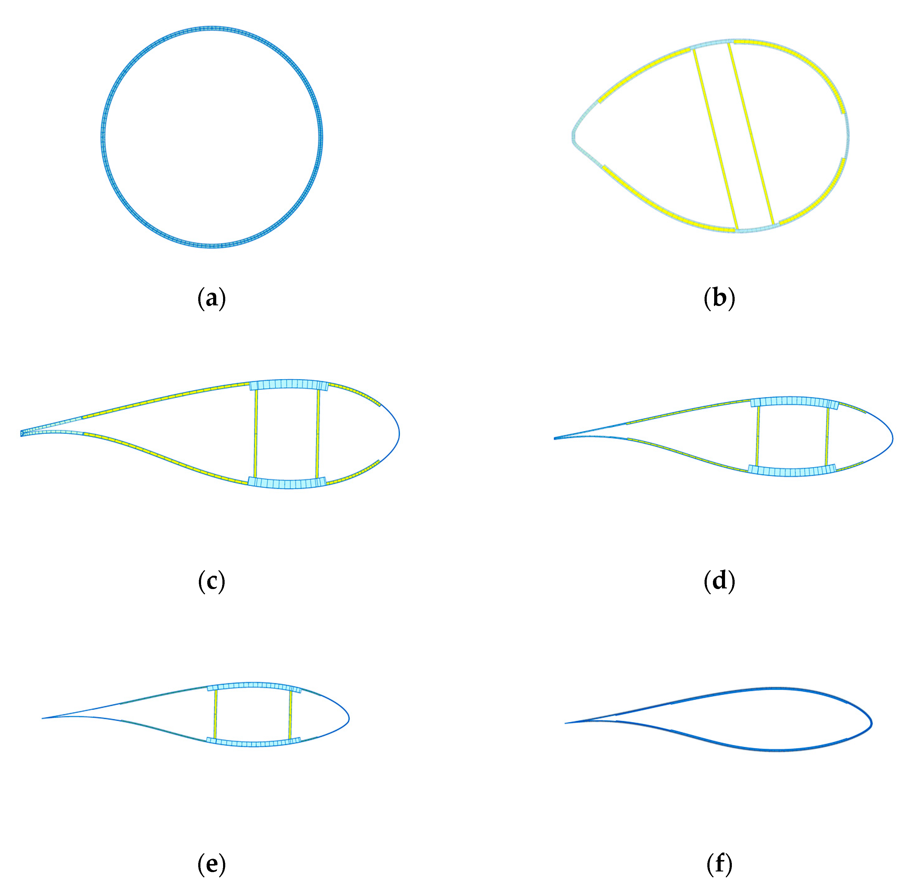
3. Composite Wind Turbine Blade

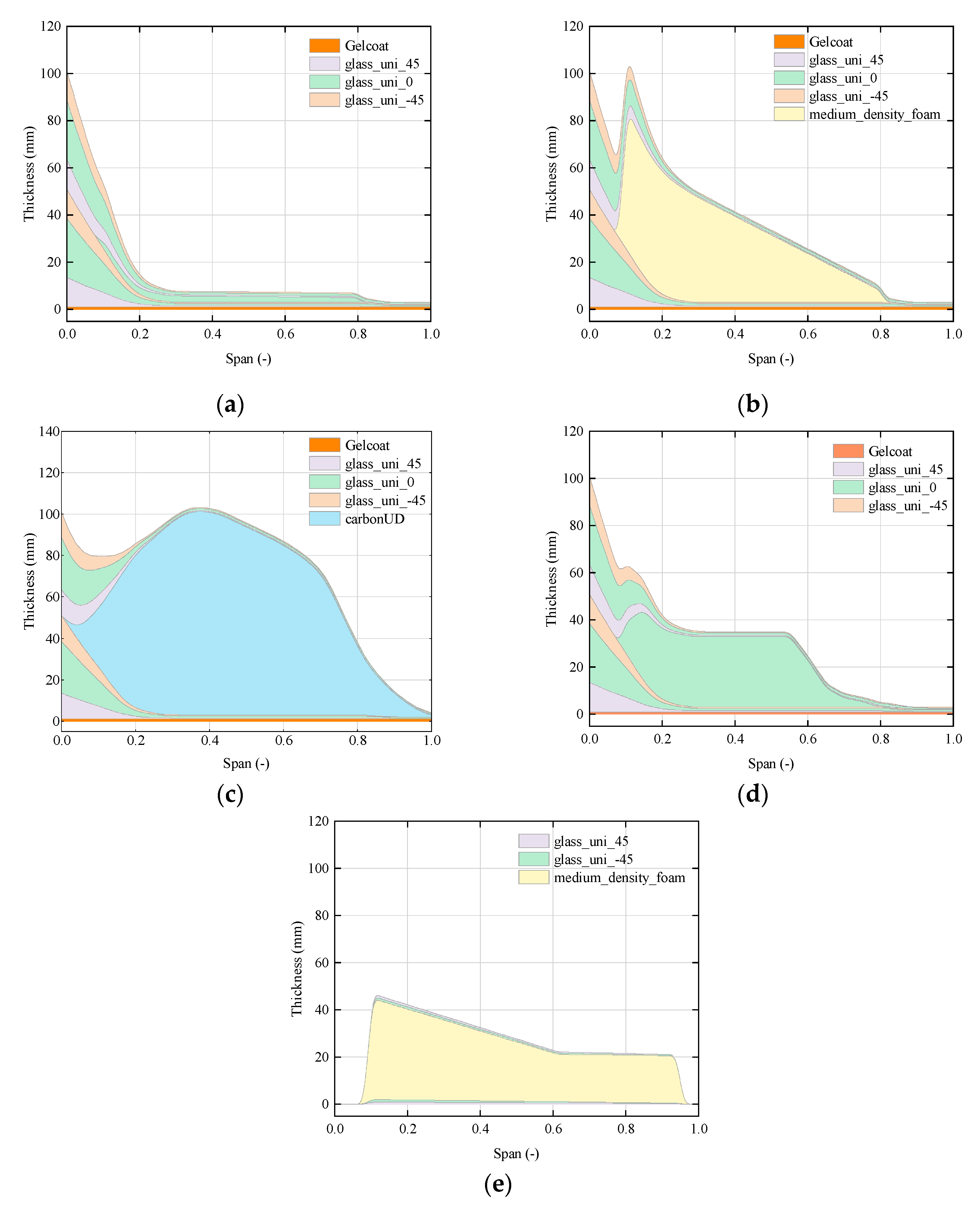
3.1. Layup and Stiffness Properties
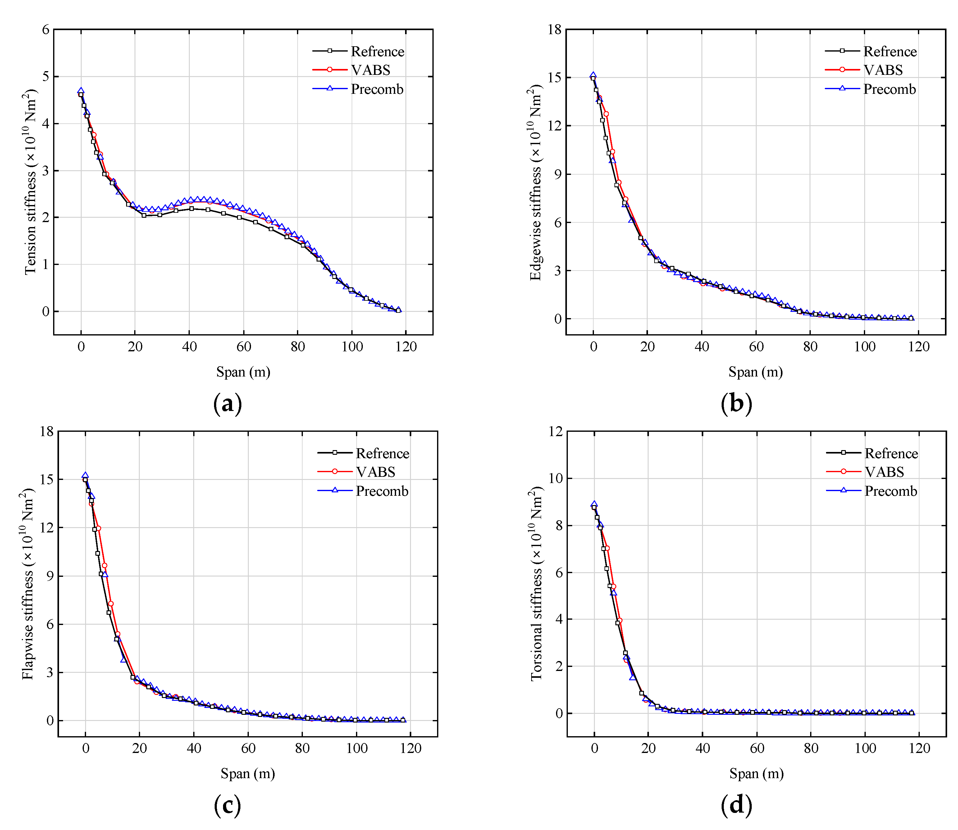
The key parameters of the IEA 15 MW RWT are shown in Table 1. The layout of the wind turbine blade cross-section is shown in Figure 3. The spar cap is reinforced with carbon fiber while the leading edge (LE) and trailing edge (TE) use uniaxial glass fiber for reinforcement. The blade has two webs connecting the suction side and pressure side, and medium density foam is added as core material to the panel and web.
While the cross-sectional layup and stiffness properties of the blade have been described in detail by [28], the previous model has some issues according to maintainers. The carbon fiber reinforced polymer (CFRP) was outdated compared to modern pultrusion manufacturing methods, and TE reinforcement was incorrectly placed too close to the root and tip of the blade [42]. Therefore, the material properties used in the work and the layup distribution at different radial locations of the blade are obtained from reference [43]. Table 2 lists the properties of the materials, including density, Young’s modulus (E1, E2, and E3), shear modulus (G1, G2, and G3), and Poisson’s ratio (υ12, υ23, and υ13). The biaxial fibers [45/−45] and triaxial fibers [45/02/−45] can be represented by multiple uniaxial fibers in different directions. And layup thickness along the radial direction for each region is shown in Figure 4. Note that the LE panel and TE panel layups are identical.

3.2. Validation

Based on the above description, NuMAD and iVABS are used to build the blade model, respectively, and PreComb and VABS are used to calculate the blade section stiffness matrix, correspondingly. PreComb is based on a modified classic laminate theory combined with a shear-flow approach [20], while VABS is based on a variational asymptotic method to compute the properties [44]. The NuMAD blade model is shown in Figure 5. The cross-sectional layups of iVABS at different span locations, including the first and last sections (s = 0, 1), the section where the web layout begins (s = 0.1), and three sections at the middle of the blade and skewed towards the tip (s = 0.47, 0.65, and 0.78), are shown in Figure 6. These layups are produced by preVABS code developed by Su et al. [45].
The calculation result of PreComb is solely for verification, while the result of VABS is used as the input file of HAWC2. The HAWC2 blade section stiffness matrix K is expressed as
K = [ K 11 K 12 K 13 K 14 K 15 K 16 K 22 K 23 K 24 K 25 K 26 K 33 K 34 K 35 K 36 s y m . K 44 K 45 K 55 K 46 K 56 K 66 ]
where K 11 and K 22 are the shear stiffness in the x and y directions, respectively. K 33 , K 44 , K 55 , and K 66 are the tension, flapwise, edgewise, and torsional stiffness, respectively. K 46 and K 56 are the flap-twist coupling term and the edge-twist coupling term, respectively.
K 46 = α K 44 × K 66 ( 1 < α < 1 )
where α denotes the flap-twist coupling factor. When it is negative, the blade flapwise bending will cause the blade to twist towards the feather.
Comparing the calculated results of the two methods with the HAWC2 reference model, as shown in Figure 7. The calculated values generally agree with the reference model data, although the tensile stiffness values are higher, which may be attributed to differences in the software and meshing strategies used in the analysis. Furthermore, Table 3 compares the natural frequencies of the blade obtained from the present study with those reported by Rinker et al. [29] and Lu et al. [41], demonstrating good agreement between the results.

3.3. Implementation of Bend–Twist Coupling

In the present work, the BTC is achieved in two ways. The first way is to change the fiber angle of the skin. The skin fibers are laid in [45/02/−45] for the entire baseline blade, which does not produce any BTC. By changing the angle θ1 and keeping θ2 = 45° to achieve unbalanced laminate, which can be symmetric or asymmetric, all cases are shown in Table 4. The second way is to change the angle of the spar cap fibers. The carbon fiber angle is set from the original 0° to 45° with a step of five degrees, equally symmetric and asymmetric. In the asymmetric case, only the angle of the pressure surface is changed.

4. Results and Discussion

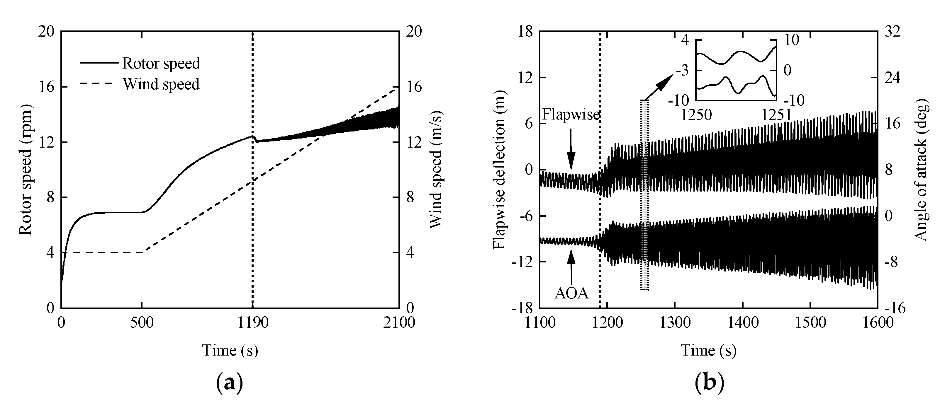
4.1. Flutter Analysis of Baseline Blade

To find the critical flutter speed of the wind turbine blade more precisely, it is necessary to consider the nonlinearity of the wind turbine. An analysis of the runaway situation has been simulated, which is a more realistic scenario where flutter may occur [47]. The wind speed is 4 m/s in the first 500 s, then increases uniformly to 2100 s, with a final wind speed of 16 m/s. Figure 8a illustrates the variations in rotor speed and wind velocity over the duration of the test. It can be seen that the rotor reaches the terminal speed at low wind speed operation [47]. After 500 s, the wind speed increases uniformly and the blades absorb more wind energy into kinetic energy so that the rotor speed increases gradually. Until 1428 s, the wind turbine speed drops down due to the partial energy of wind turbine rotation transformed into violent vibration of the blades, which implies the occurrence of instability, and the rotor speed at this time is 12.31 r/min. Figure 8b shows the variation of blade tip flapwise displacement and angle of attack (AOA) near the instability phenomenon. Before the onset of instability, the flapwise displacement ranges from −2.48 to −0.61 m and the AOA variation ranges from −3.88° to −4.95° during 1150~1155 s. After the onset of instability, the variation range of flapwise displacement and AOA is continuously expanding, indicating a diverging trend. Within 1595~1600 s, the flapwise displacement motion range was −3.44~7.43 m, and the whole variation interval increased by 9.00 m. The maximum AOA variation range was −12.17°~1.49°and the range increased by 12.58°. By observing the flapwise displacement and AOA during 1250~1251 s, it can be found that there is a phase difference between them, indicating the coupling between flapwise and torsional motions [48].

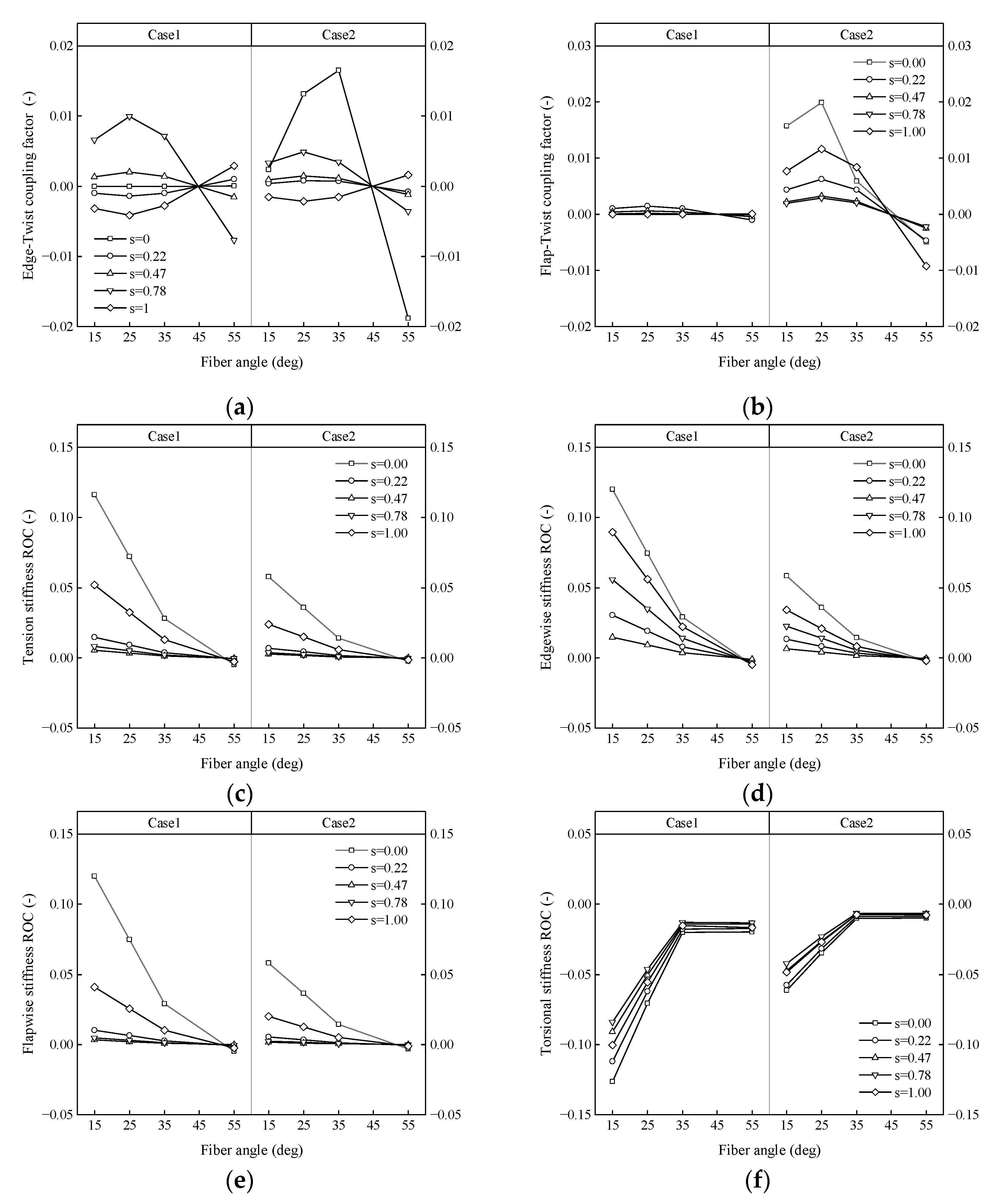
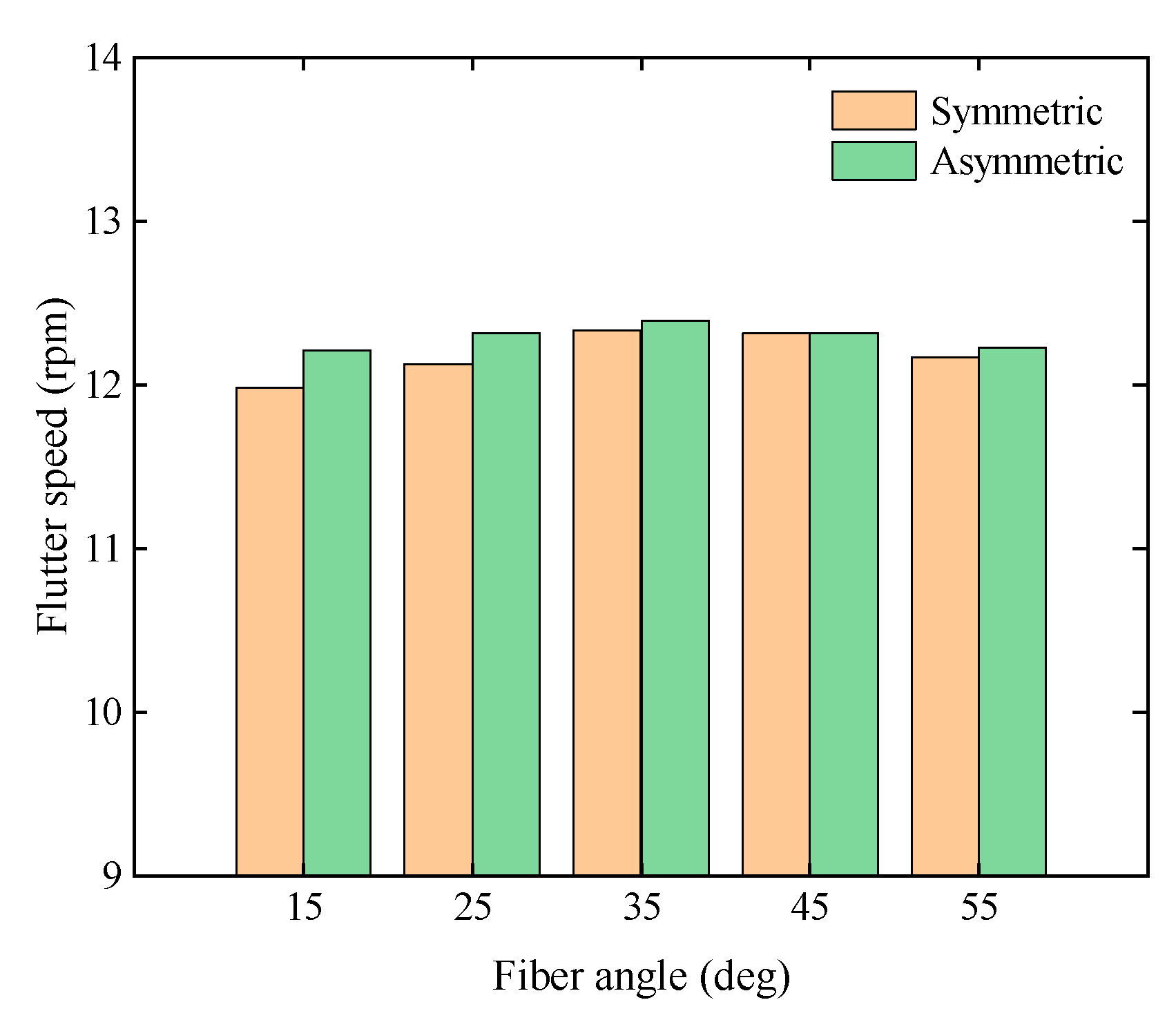
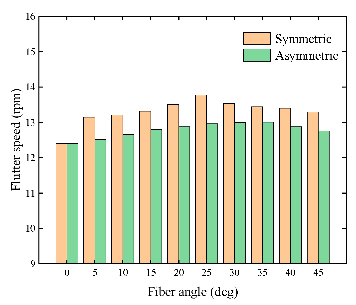
4.2. Effect of Skin Fiber Angle

Case1 involves changing the fiber orientation of the full blade skin, while case2 only changes the fiber angle on the suction side. Figure 9 shows the effect of fiber angle on structural properties for five span locations of blade: s = 0, 0.22, 0.47, 0.78, 1. From Figure 9a,b, it is observed that the edge-twist coupling factor is maximum at θ1 = 35° only for asymmetric skin and s = 0. In all other cases, the edge-twist coupling factor achieves the maximum value at θ1 = 25°. The flap-twist coupling factor for symmetric skin is almost 0, which indicates that symmetric skin hardly introduces coupling of flapwise and twist, and the maximum value for asymmetric skin is achieved at θ1 = 25°. However, it can be determined that the BTC caused by the skin fiber angle is very low, with the maximum values of edge-twist and flap-twist coupling factors being 0.019 and 0.020.
Figure 9c–f demonstrate that both symmetric and asymmetric skins experience a decrease in tension, edgewise stiffness, and flapwise stiffness of the blade as the fiber angle increases. Meanwhile, the torsional stiffness increases for θ1 less than 45° and decreases for θ1 greater than 45° with increasing fiber angle. And the closer to the blade root, the more obvious this trend is. That is because the skin thickness value at the blade root is the largest compared to other span positions of the blade. At the blade root (i.e., s = 0), case1-1 (i.e., a layup with off-axis fiber angle θ1 = 15 in full blade) showed an increase of 11.60%, 11.99%, and 12.00% in tension, edgewise and flapwise stiffness, respectively, and a reduction of 12.64% in torsional stiffness. As fiber angle greater than 45°, for case1-4 (i.e., a layup with off-axis fiber angle θ1 = 55 in full blade), the tension, edgewise, flapwise, and torsional stiffness showed a slight decrease of 0.48%, 0.50%, 0.50%, and 1.96%, respectively. Comparing case1 and case2, it is found that the impact of fiber angle on stiffness is more pronounced for blades with symmetric skins than for those with asymmetric skins. The reason why this phenomenon occurs is that symmetric skins change the fiber angle throughout the entire blade, while asymmetric skins only change the fiber angle on the suction side. For case2-1 (i.e., a layup with off-axis fiber angle θ1 = 15 on the suction side of the blade), the rates of change (ROCs) of the tension, edgewise, flapwise, and torsional stiffness are 5.78%, 5.82%, 5.79%, and −6.14%, respectively. For case2-4 (i.e., a layup with off-axis fiber angle θ1 = 55° on the suction side of the blade), the four ROCs are 0.25%, 0.26%, 0.31%, and −1.00%, respectively.
A comparison between the flutter limits of blades with symmetric and asymmetric skin is shown in Figure 10. Compared with the baseline (θ1 = 45°), the flutter speed is slightly increased at θ1 = 35°, the flutter speed decreases at all other angles, and the minimum value of flutter speed is obtained at θ1 = 15°. This phenomenon may be explained by the fact that when θ1 = 35°, the reduction in torsional stiffness is minimal and there is a certain positive flap-twist coupling factor. At the same fiber angle, it was observed that the asymmetric blade exhibited a higher flutter speed compared to the symmetric blade. The reason for this may be attributed to the smaller reduction in torsional stiffness and the larger flap-twist coupling factor of the asymmetric blade. In the case of the symmetric blade, the maximum flutter speed was observed to be 12.33 rpm, with a minimum of 11.98 rpm. This represents a ROC of 0.08% and −2.76% compared to the baseline. On the other hand, for the asymmetric blade, the maximum flutter speed was 12.39 rpm, with a minimum of 12.21 rpm. The ROC of flutter speed was found to be 0.57% and −0.89% compared to the baseline. Higher flutter speeds mean less risk of flutter during turbine operation, which is critical for the safe operation of wind turbines.

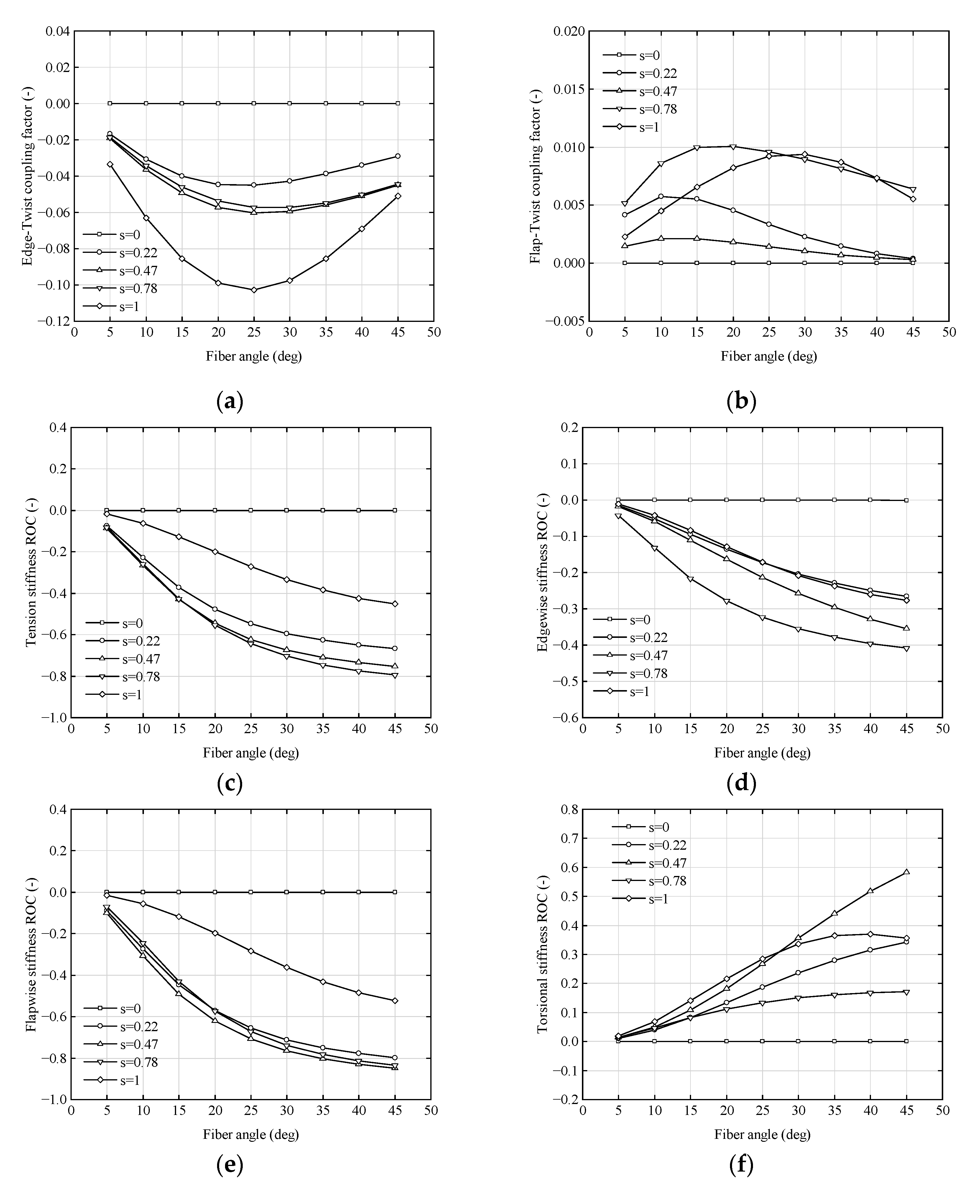
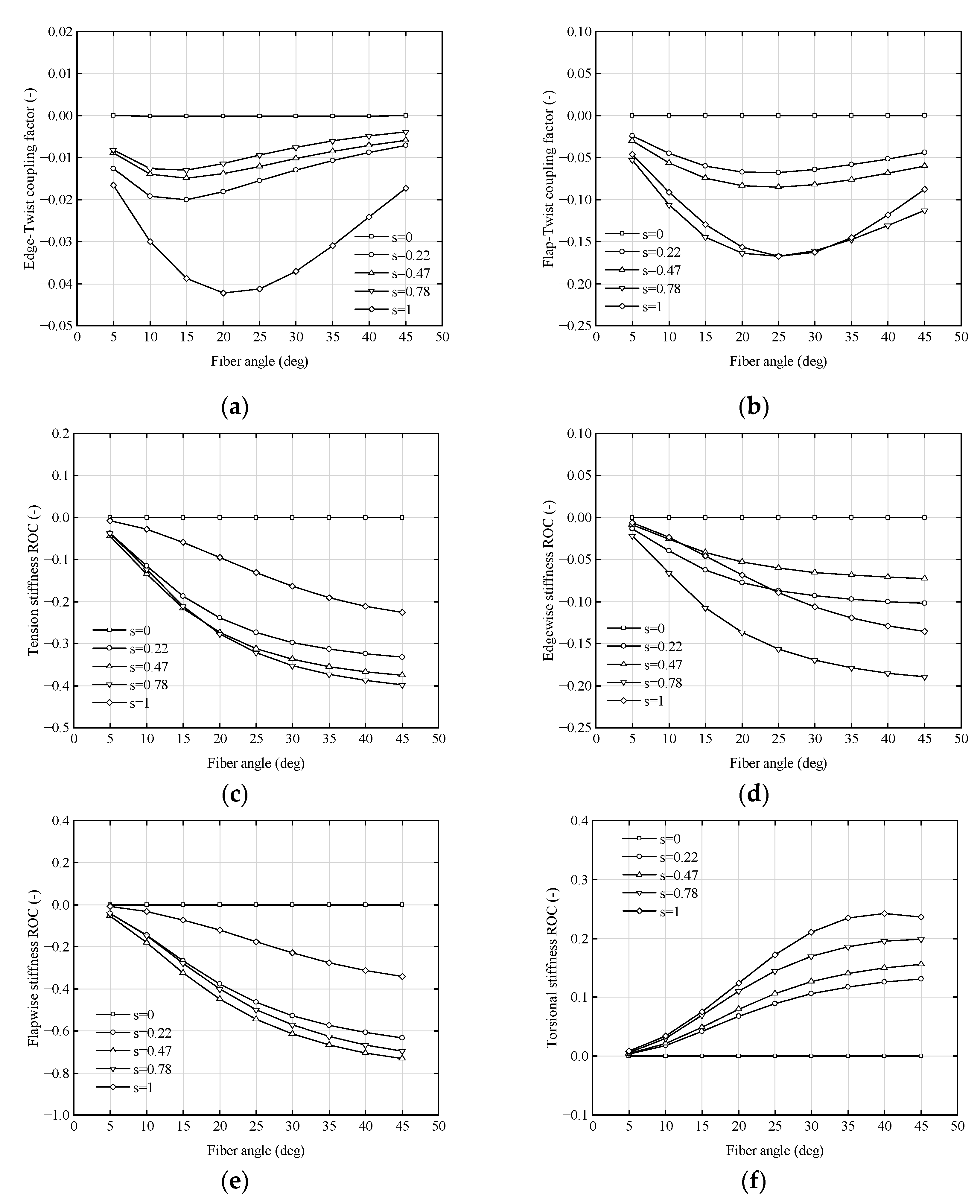
4.3. Effect of Carbon Fiber Angle of the Spar Cap

Similar to the skin fiber angle case, fiber angle changes in the spar cap can also be divided into symmetric and asymmetric cases. The main difference is that in the asymmetric layup, the fiber angle on the pressure side is changed instead of the suction side. Figure 11 illustrates the variation of blade structural properties with respect to fiber angle at five radial positions of the blade (s = 0, 0.22, 0.47, 0.78, 1) in the case of the symmetric layup. It can be observed that all values at the blade root (i.e., s = 0) remain almost constant and are always close to 0, regardless of the fiber angle. The explanation for this is the extremely small thickness of the carbon fiber, resulting in minimal changes to blade properties when its angle is altered.
As shown in Figure 11a,b, the edge-twist and flap-twist coupling factors exhibit a trend of initially increasing and then decreasing with the fiber angle at the other four positions. Specifically, the edge-twist coupling factor reaches its maximum bending–twist coupling at a fiber angle of 25°, with a maximum negative value of −0.103 at s = 1, while the flap-twist coupling factor has a smaller maximum positive value of 0.010 at s = 0.78. These observations suggest that changing the fiber angle of a symmetric spar cap introduces stronger coupling between edgewise and twist, but weaker coupling between flapwise and twist. Figure 11c–f demonstrate that the stiffness of tension, edgewise and flapwise, decreases as the fiber angle increases. Furthermore, tension and flapwise stiffness exhibit greater sensitivity to changes in fiber angle than edgewise stiffness. At a fiber angle of 45 degrees, the flapwise stiffness at s = 0.47 experiences a maximum decrease of 84.98%, while the tension and edgewise stiffness at s = 0.78 experience a maximum decrease of 77.39% and 40.84%, respectively. The torsional stiffness at each position increases somewhat compared to the baseline at any angle. Generally, the torsional stiffness increases with an increasing fiber angle, except at the tip of the blade (s = 1) where the torsional stiffness at a fiber angle of 45° is slightly lower than that for 40°. When s = 0.47 and the fiber angle is 45°, the torsional stiffness achieves a maximum increase of 58.32%.
For asymmetric layup (i.e., changing only the fiber angle at the pressure surface), the variations of blade structural properties with fiber angle are displayed in Figure 12. Similar to symmetric layup, the cross-sectional properties at s = 0 exhibit little variation with angle, remaining close to 0. Similarly, at the other four positions, bend–twist coupling exhibits an increasing-then-decreasing trend, with the maximum coupling occurring at s = 1. However, the fiber angles at which the maximum negative values are attained differ: edgewise bend–twist coupling has a maximum negative value of −0.042 at a fiber angle of 20°, whereas flapwise bend–twist coupling reaches a maximum negative value of −0.168 at a fiber angle of 25°. The evidence suggests that the asymmetric spar cap leads to significant flap-twist coupling, whereas edgewise bend–twist coupling is minor. This finding is in contrast to the case of a symmetric spar cap. The behavior of tension, edgewise, flapwise, and torsional stiffness with respect to fiber angle is consistent with that of the symmetric layup. However, the asymmetric layup is less sensitive to changes in fiber angle than the symmetric layup. At a fiber angle of 45°, the maximum decreases in tension and edgewise stiffness are 39.77% and 18.96% at s = 0.78, respectively, while the maximum decrease in flapwise stiffness is 73.19% at s = 0.47. The ROC of torsional stiffness achieves a maximum value of 24.29% at s = 1 for a fiber angle of 40°.
Figure 13 illustrates the trend of flutter speed with changes in the spar cap carbon fiber angle for both symmetric and asymmetric layups. It is clear that, compared to the baseline, there is an increase in flutter speed for both symmetric and asymmetric layups. Moreover, changing the carbon fiber angle in the entire spar cap area is more effective in increasing flutter speed than changing only the pressure side. The phenomenon may be due to the fact that torsional stiffness increases more significantly with a symmetric layup, while the flap-twist coupling of an asymmetric layup causes the blade to twist towards the feather during bending. When the spar cap is laid symmetrical, the flutter speed increases and then decreases as the fiber angle is changed from 5 to 45°. The maximum value of 13.51 rpm is achieved at a fiber angle of 25°, which is 9.66% higher than the baseline. In contrast, for the asymmetric layup, the maximum flutter speed of 12.88 rpm is achieved at a fiber angle of 30°, which is 4.55% higher than the baseline.

5. Conclusions

A parametric approach was utilized to investigate the impact of the BTC effect on the properties and the flutter limit of ultra-long flexible composite blades resulting from modifications to the fiber angles of the skin and spar cap. The IEA 15 MW RWT blade model was established, and the structural properties were analyzed, revealing a general agreement with the reference model. By altering the angles of the fibers in the skin and spar cap, the characteristics of BTC blades were obtained. The flutter limits of the BTC blades were predicted using HAWC2 version 12.8 software, and the optimal layup configuration was determined. The results show that a symmetric spar cap will result in higher flutter speed but also lower stiffness compared to an asymmetric layup, while the skin has a minor influence. The research findings can provide guidance for the anti-flutter design of ultra-long flexible wind turbine blades with bend–twist coupling.
The BTC resulting from changes in the skin fiber angle is small, with a maximum value of 0.020. Increasing the fiber angle results in a decrease in tension, edgewise, and flapwise stiffness of the blade, as well as an increase in torsional stiffness for angles less than 45° and a decrease for angles greater than 45°. This trend is more pronounced closer to the blade root. Compared to asymmetric layup, the blade stiffness of symmetric layup is more sensitive to changes in the fiber angle. At a fiber angle of 15°, the maximum increment in tension, edgewise, and flapwise stiffness at the root of the blade for symmetric layup is 11.60%, 11.99%, and 12.00%, respectively. Meanwhile, the maximum reduction in torsional stiffness is 12.64%. For asymmetric layup, the corresponding stiffness increments are 5.78%, 5.82%, 5.79%, and a reduction of 6.14%, respectively.
The flutter limit is higher for asymmetric skin than for symmetric skin. However, for both symmetric and asymmetric skin, the flutter velocity only slightly increases at a fiber angle of 35° and is somewhat reduced at all other angles, with the minimum value obtained at a fiber angle of 15°. Compared to the baseline, the symmetric skin blade showed a maximum increase of 0.08% in flutter speed, with a corresponding decrease of 2.76% in the minimum value. In contrast, the asymmetric skin blade exhibited a maximum increase of 0.57% in flutter speed, with a corresponding decrease of 0.89% in the minimum value.
The study on spar cap carbon fiber angle parameterization reveals that the symmetric layup has a greater impact on blade characteristics and flutter limits compared to the asymmetric layup. The bend–twist coupling increases and then decreases as the fiber angle increases. The maximum negative edge-twist coupling factor for the symmetric layup is −0.103 at a fiber angle of 25°, while for the asymmetric layup, it is −0.042 at a fiber angle of 20°. The flap-twist coupling of the symmetric layup is negligible, with a maximum value of only 0.010, and the asymmetric layup achieves a maximum negative value of −0.168 at a fiber angle of 25°. Tension, edgewise, and flapwise stiffness decrease with increasing fiber angle, while torsional stiffness generally increases. The symmetric layup experiences maximum reductions of 79.48%, 84.98%, and 40.84% in tension, edgewise, and flapwise stiffness, respectively. In contrast, for the asymmetric layup, the corresponding reductions are 39.77%, 18.96%, and 73.19%. The maximum increase in torsional stiffness is 58.32% for the symmetric layup, while for the asymmetric layup, it is 24.29%.
Both the symmetric and asymmetric spar cap layups can increase the chattering speed, but the effect of the symmetric layup on the flutter speed is more significant. As the fiber angle increases, the flutter limit first increases and then decreases. The flutter speed for the symmetric layup reaches a maximum of 13.51 rpm at a fiber angle of 25°, which represents a 9.66% increase compared to the baseline. For the asymmetric layup, the maximum chattering speed of 12.88 rpm is achieved at a fiber angle of 30°, which represents a 4.55% increase compared to the baseline.
At present, only the effect of bend–twist coupling due to fiber angle on blade characteristics and flutter limit has been investigated. Investigating the BTC caused by material and layup thickness imbalance, as well as different ply angles in various sections, and the effect of BTC on the operational performance of wind turbine, particularly power generation, could be a further extension of this work.

Author Contributions

Conceptualization, B.L. and D.T.; methodology, B.L. and D.T.; software, B.L.; validation, X.W. and Y.S.; formal analysis, X.W. and Y.S.; investigation, B.L.; resources, H.M.; data curation, H.M.; writing—original draft preparation, B.L.; writing—review and editing, D.T.; visualization, X.W.; supervision, D.T.; project administration, D.T.; funding acquisition, D.T. All authors have read and agreed to the published version of the manuscript.

Funding

This research was funded by the Ministry of Science and Technology of the People’s Republic of China (no.: 2018YFB1501304), which provided financial support for this study.

Data Availability Statement

The data presented in this study are available at the request of the corresponding author. The data are not publicly available due to the content of confidential information/trade secrets in them.

Conflicts of Interest

The authors declare no conflict of interest.

Abbreviations

GWECGlobal Wind Energy Council
BTCbend–twist coupling
RWTreference wind turbine
BEMblade element momentum
LEleading edge
TEtrailing edge
CFRPcarbon fiber reinforced polymer
AOAangle of attack
ROCrate of change

References

  1. GWEC. Global Offshore Wind Report 2022; Technical Report; GWEC: Brussels Belgium, 2022. [Google Scholar]
  2. Reddy, S.; Suresh, R.; Hanamantraygouda, M.B. Use of composite materials and hybrid composites in wind turbine blades. Mater. Today Proc. 2021, 46, 2827–2830. [Google Scholar] [CrossRef]
  3. Mishnaevsky, J.L.; Branner, K.; Petersen, H.N. Materials for wind turbine blades: An overview. Materials 2017, 10, 1285. [Google Scholar] [CrossRef] [Green Version]
  4. Bortolotti, P.; Johnson, N.; Abbas, N.J. Land-based wind turbines with flexible rail-transportable blades–Part 1: Conceptual design and aeroservoelastic performance. Wind Energy Sci. 2021, 6, 1277–1290. [Google Scholar] [CrossRef]
  5. Veers, P.; Dykes, K.; Lantz, E. Grand challenges in the science of wind energy. Science 2019, 366, 1–9. [Google Scholar] [CrossRef] [PubMed] [Green Version]
  6. Gao, Q.; Cai, X.; Guo, X. Parameter sensitivities analysis for classical flutter speed of a horizontal axis wind turbine blade. J. Cent. South Univ. 2018, 25, 1746–1754. [Google Scholar] [CrossRef]
  7. Kelley, C.L.; Paquette, J. Investigation of flutter for large; highly flexible wind turbine blades. J. Phys. Conf. Ser. IOP Publ. 2020, 1618, 052078. [Google Scholar] [CrossRef]
  8. Chetan, M.; Yao, S.; Griffith, D.T. Flutter behavior of highly flexible blades for two-and three-bladed wind turbines. Wind Energy Sci. 2022, 7, 1731–1751. [Google Scholar] [CrossRef]
  9. Veers, P.; Bir, G.; Lobitz, D. Aeroelastic tailoring in wind-turbine blade applications. In Proceedings of the Windpower ’98, Bakersfield, CA, USA, 27 April–1 May 1998. [Google Scholar]
  10. Lobitz, D.; Veers, P.; Laino, D. Performance of twist-coupled blades on variable speed rotors. 2000 ASME Wind Energy Symp. 2000, 62, 404–412. [Google Scholar]
  11. Lobitz, D.W.; Veers, P.S. Load mitigation with bending/twist-coupled blades on rotors using modern control strategies. Wind Energy 2003, 6, 105–117. [Google Scholar] [CrossRef]
  12. Bottasso, C.L.; Campagnolo, F.; Croce, A. Optimization-based study of bend–twist coupled rotor blades for passive and integrated passive/active load alleviation. Wind Energy 2013, 16, 1149–1166. [Google Scholar] [CrossRef]
  13. Bagherpour, T.; Manolas, D.I.; Riziotis, V.A. Modeling of material bend-twist coupling on wind turbine blades. Compos. Struct. 2018, 193, 237–246. [Google Scholar] [CrossRef]
  14. Meng, H.; Lien, F.S.; Glinka, G. Study on fatigue life of bend-twist coupling wind turbine blade based on anisotropic beam model and stress-based fatigue analysis method. Compos. Struct. 2019, 208, 678–701. [Google Scholar] [CrossRef]
  15. Chen, J.; Shen, X.; Zhu, X. Study on composite bend-twist coupled wind turbine blade for passive load mitigation. Compos. Struct. 2019, 213, 173–189. [Google Scholar] [CrossRef]
  16. Yu, W.B. VABS Manual for Users; Purdue University: West Lafayette, IN, USA, 2021. [Google Scholar]
  17. Lobitz, D.; Paul, V. Aeroelastic behavior of twist-coupled HAWT blades. In Proceedings of the 1998 ASME Wind Energy Symposium, Reno, NV, USA, 12–15 January1998. [Google Scholar]
  18. Stäblein, A.R.; Morten, H.H.; Verelst, D.R. Modal properties and stability of bend–twist coupled wind turbine blades. Wind Energy Sci. 2017, 2, 343–360. [Google Scholar] [CrossRef] [Green Version]
  19. Shakya, P.; Sunny, M.R.; Maiti, D.K. A parametric study of flutter behavior of a composite wind turbine blade with bend-twist coupling. Compos. Struct. 2019, 207, 764–775. [Google Scholar] [CrossRef]
  20. Bir, G.S. User’s Guide to PreComp; National Renewable Energy Laboratory: Golden, CO, USA, 2006. [Google Scholar]
  21. Jonkman, B.; Mudafort, R.M.; Platt, A. OpenFAST/openfast: OpenFAST v3.1.0; Zenodo [Code]. 2022. Available online: https://zenodo.org/record/6324288#.ZAFU2h9BxPY (accessed on 10 May 2023).
  22. Larsen, T.J.; Hansen, A.M. How 2 HAWC2; The User’s Manual; DTU Wind Energy: Roskilde, Denmark, 2019. [Google Scholar]
  23. DNV GL: Bladed User Manual Version 4.9; Garrad Hassan & Partners Ltd.: Bristol, UK, 2018; Available online: https://www.dnv.com/services/wind-turbine-design-software-bladed-3775 (accessed on 10 May 2023).
  24. Shakya, P.; Sunny, M.R.; Maiti, D.K. Nonlinear flutter analysis of a bend-twist coupled composite wind turbine blade in time domain. Compos. Struct. 2022, 284, 115–216. [Google Scholar] [CrossRef]
  25. Hayat, K.; Lecea, A.G.M.; Moriones, C. D Flutter performance of bend-twist coupled large-scale wind turbine blades. J. Sound Vib. 2016, 370, 149–162. [Google Scholar] [CrossRef]
  26. Zhou, X.; Huang, K.; Li, Z. Effects of bend-twist coupling on flutter limits of composite wind turbine blades. Compos. Struct. 2018, 192, 317–326. [Google Scholar] [CrossRef]
  27. Torregrosa, A.J.; Gil, A.; Quintero, P.; Cremades, A. On the effects of orthotropic materials in flutter protection of wind turbine flexible blades. J. Wind Eng. Ind. Aerodyn. 2022, 227, 105055. [Google Scholar] [CrossRef]
  28. Gaertner, E.; Rinker, J.; Sethuraman, L. Definition of the IEA Wind 15-Megawatt Offshore Reference Wind Turbine; National Renewable Energy Laboratory: Golden, CO, USA, 2020. [Google Scholar]
  29. Rinker, J.; Gaertner, E.; Zahle, F. Comparison of loads from HAWC2 and OpenFAST for the IEA Wind 15 MW Reference Wind Turbine. J. Phys. Conf. Ser. 2020, 1618, 052052. [Google Scholar] [CrossRef]
  30. Fritz, E.K.; Ferreira, C.; Boorsma, K. An efficient blade sweep correction model for blade element momentum theory. Wind Energy 2022, 25, 1977–1994. [Google Scholar] [CrossRef]
  31. Scott, S.; Greaves, P.; Macquart, T.; Pirrera, A. Comparison of blade optimisation strategies for the IEA 15 MW reference turbine. J. Phys. Conf. Ser. 2022, 2265, 032029. [Google Scholar] [CrossRef]
  32. Trigaux, F.; Chatelain, P.; Winckelmans, G. Impact of the rotor blades elasticity on the loads and wake of the large IEA 15-MW wind turbine. J. Phys. Conf. Ser. 2023, 2505, 012034. [Google Scholar] [CrossRef]
  33. Oliveira, M.; Silva, L.; Puraca, R.; Carmo, B. CFD Investigation of the IEA Offshore 15 MW Reference Wind Turbine performance in full scale: A temporal discretization analysis. In Proceedings of the ASME 2023 International Conference 2023, Melbourne, Australia, 11–16 June 2023. [Google Scholar]
  34. Loubeyres, J.; Pfister, J.-L.; Blondel, F.; Guy, N. Stall flutter instabilities on the IEA-15 reference wind turbine in idling conditions: Code-to-code comparisons and physical analyses. J. Phys. Conf. Ser. 2022, 2265, 032019. [Google Scholar] [CrossRef]
  35. Tian, S.; Du, H.D.; Tao, F. iVABS(Version 0.7) [Software]. 2022. Available online: https://github.com/wenbinyugroup/ivabs/releases/tag/v0.7 (accessed on 25 April 2023).
  36. Camarena, E.; Anderson, E.; Ruehl, K. NuMAD v3.0 (3.0). Zenodo. 2022. Available online: https://zenodo.org/record/5851606 (accessed on 25 April 2023).
  37. Madsen, H.A.; Larsen, T.J.; Pirrung, G.R. Implementation of the blade element momentum model on a polar grid and its aeroelastic load impact. Wind Energy Sci. 2020, 5, 1–27. [Google Scholar] [CrossRef] [Green Version]
  38. Sriti, M. Tip loss factor effects on aerodynamic performances of horizontal axis wind turbine. Energy Procedia 2017, 118, 136–140. [Google Scholar]
  39. Lobitz, D.W. Aeroelastic stability predictions for a MW-sized blade. Wind Energy 2004, 7, 211–224. [Google Scholar] [CrossRef]
  40. Hansen, M.H. A Beddoes-Leishman Type Dynamic Stall Model in State-Space and Indicial Formulations; Technical Report; Riso National Laboratory: Roskilde, Denmark, 2004. [Google Scholar]
  41. Kim, T.; Hansen, A.M.; Branner, K. Development of an anisotropic beam finite element for composite wind turbine blades in multibody system. Renew. Energy 2013, 59, 172–183. [Google Scholar] [CrossRef] [Green Version]
  42. Garrett, B. IEA Wind 15-MW Release Notes. Available online: https://github.com/IEAWindTask37/IEA-15-240-RWT/blob/master/ReleaseNotes.md (accessed on 25 April 2023).
  43. Bortolotti, P.; Barter, G.; Gaertner, E. IEA 15 MW Offshore Reference Turbine; with Taped Chord Tip Design. Available online: https://github.com/IEAWindTask37/IEA-15-240-RWT/blob/master/WT_Ontology/IEA-15-240-RWT.yaml (accessed on 25 April 2023).
  44. Hodges, D.H. Nonlinear Composite Beam Theory; American Institute of Aeronautics and Astronautics: Washington, WA, USA, 2006. [Google Scholar]
  45. Tian, S.; Liu, X.; Yu, W. PreVABS Manual; Purdue University: West Lafayette, IN, USA, 2018; Available online: https://cdmhu b.org/resources/1597 (accessed on 25 April 2023).
  46. Lu, M.M.; Ke, S.T.; Wu, H.X. A novel forecasting method of flutter critical wind speed for the 15 MW wind turbine blade based on aeroelastic wind tunnel test. J. Wind Eng. Ind. Aerodyn. 2022, 230, 105195. [Google Scholar] [CrossRef]
  47. Bak, C.; Zahle, F.; Bitsche, R. The DTU 10-MW Reference Wind Turbine; DTU Wind Energy: Roskilde, Denmark, 2013. [Google Scholar]
  48. Holierhoek, J.G. Aeroelastic Stability Models: Handbook of Wind Energy Aerodynamics; Springer: Cham, Switzerland, 2020; pp. 1–44. [Google Scholar]
Figure 1. Schematic diagram of the polar grid BEM.
Energies 16 05829 g001
Figure 2. Schematic diagram of the co-ordinate system in HAWC2.
Energies 16 05829 g002
Figure 3. Illustration of the cross-section geometry.
Energies 16 05829 g003
Figure 4. Blade layup: (a) thickness of layers in the LE reinforcement; (b) thickness of layers in the LE and TE panel; (c) thickness of layers in the spar; (d) thickness of layers in the TE reinforcement; and (e) thickness of layers in the web.
Energies 16 05829 g004
Figure 5. Blade model established by NuMAD.
Energies 16 05829 g005
Figure 6. Cross-sectional layout at different spans locations: (a) s = 0; (b) s = 0.1; (c) s = 0.47; (d) s = 0.65; (e) s = 0.78; and (f) s = 1.
Energies 16 05829 g006
Figure 7. Comparison of blade stiffness properties: (a) tension stiffness; (b) edgewise stiffness; (c) flapwise stiffness; and (d) torsional stiffness.
Energies 16 05829 g007
Figure 8. (a) Rotor speed and wind speed; (b) blade tip flapwise displacement and AOA near the instability phenomenon.
Energies 16 05829 g008
Figure 9. Variation of blade structural properties at different span locations with respect to skin fiber angle: (a) edge-twist coupling factor; (b) flap-twist coupling factor; (c) ROC for tension stiffness; (d) ROC for edgewise stiffness; (e) ROC for flapwise stiffness; and (f) ROC for torsional stiffness.
Energies 16 05829 g009
Figure 10. Flutter speed at different ply angles for wind turbine blades with symmetric or asymmetric skin.
Energies 16 05829 g010
Figure 11. Variation of blade structural properties at different span locations with respect to symmetric spar cap fiber angle: (a) edge-twist coupling factor; (b) flap-twist coupling factor; (c) ROC for tension stiffness; (d) ROC for edgewise stiffness; (e) ROC for flapwise stiffness; and (f) ROC for torsional stiffness.
Energies 16 05829 g011
Figure 12. Variation of blade structural properties at different span locations with respect to asymmetric spar cap fiber angle: (a) edge-twist coupling factor; (b) flap-twist coupling factor; (c) ROC for tension stiffness; (d) ROC for edgewise stiffness; (e) ROC for flapwise stiffness; and (f) ROC for torsional stiffness.
Energies 16 05829 g012
Figure 13. Flutter speed at different angles for wind turbine blades with symmetric or asymmetric spar cap.
Energies 16 05829 g013
Table 1. Main parameters for the IEA 15 MW reference wind turbine.
ParametersValues
Rated power15 MW
Blade number3
Blade length117 m
Rated rotor speed7.56 rpm
Hub height150 m
Rated wind speed10.59 m/s
Blade prebend4 m
Blade mass65 t
Table 2. Material properties.
MaterialDensity (kg/m3)E1
(MPa)
E2
(MPa)
E3
(MPa)
G1
(MPa)
G2
(MPa)
G3
(MPa)
υ12υ23υ13
Gelcoat12353440344034401323132313230.30.30.3
Glass_uni194044,60017,00016,7003270348035000.2620.350.264
Carbon UD1220114,500839083905990599059900.270.270.27
Foam130129.2129.2129.248.9548.9548.950.320.320.32
Table 3. Natural frequencies of IEA 15 MW blade.
ModeFrequency
Present StudyReference ModelRinker [29]Lu [46]
First-order flapwise0.5120.5040.5210.555
First-order edgewise0.6920.6910.6190.642
Second-order flapwise1.5091.4761.5591.598
Second-order edgewise2.1202.1341.9331.925
Third-order flapwise2.9922.9293.0783.016
Third-order edgewise4.2784.2914.156-
First-order torsion4.3144.3714.4753.911
Table 4. Skin fiber angle orientation.
CasesSymmetric/
Asymmetric
SubcasesTriax Glass Fiber
Angle Orientation
[+θ1/02/−θ2]
Region of Changing Fiber Angle Orientation
θ1θ2
1Symmetric11545Full blade
22545
33545
45545
2Asymmetric11545Suction side
22545
33545
45545
Disclaimer/Publisher’s Note: The statements, opinions and data contained in all publications are solely those of the individual author(s) and contributor(s) and not of MDPI and/or the editor(s). MDPI and/or the editor(s) disclaim responsibility for any injury to people or property resulting from any ideas, methods, instructions or products referred to in the content.

