
Utilization of MnFe2O4 Redox Ferrite for Solar Fuel Production via CO2 Splitting: A Thermodynamic Study


Abstract
:1. Introduction
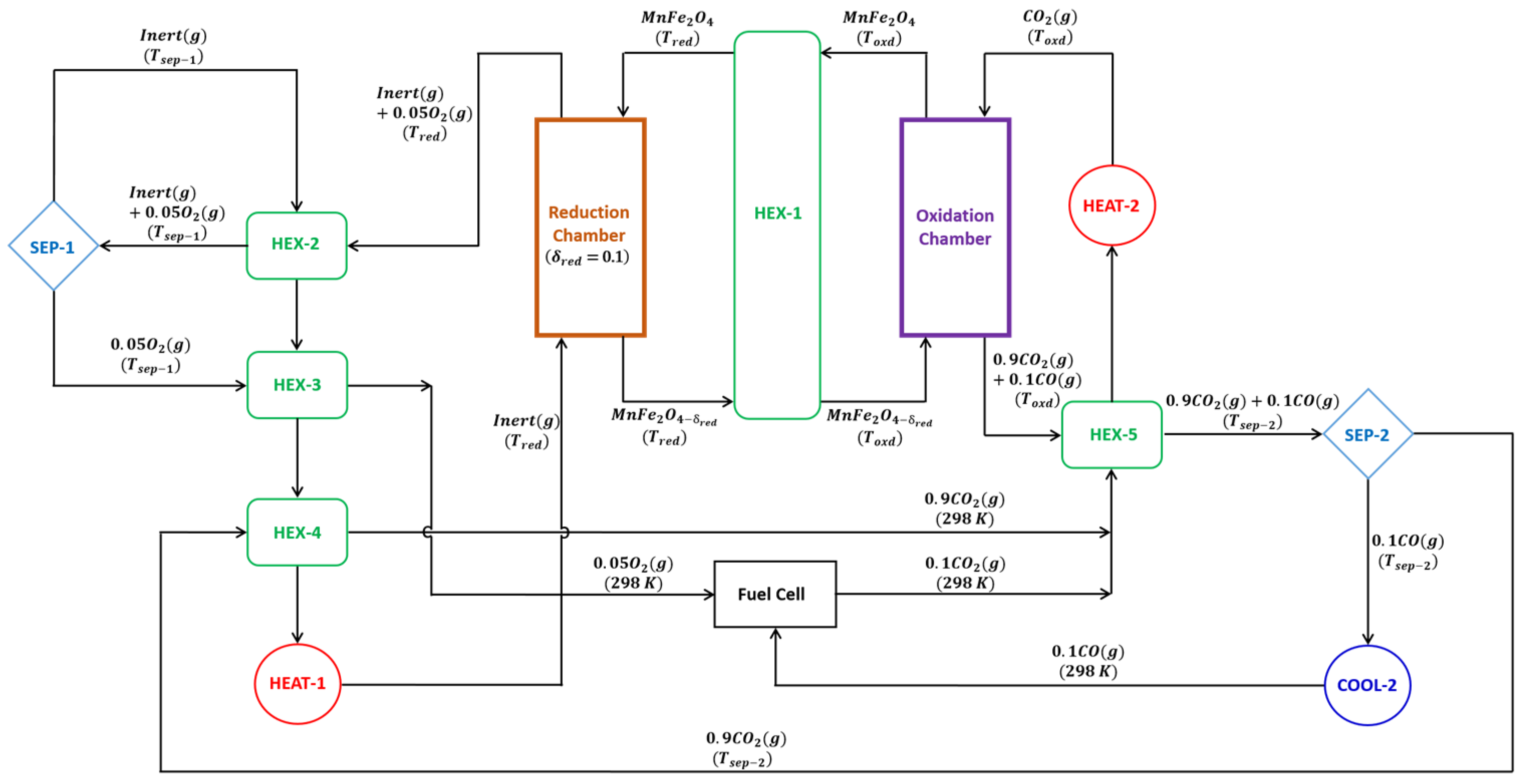
2. Thermodynamic Model and Equations
- (1)
- All processes operated at steady-state;
- (2)
- Ideal gas behavior;
- (3)
- Reduction, as well as oxidation chambers, are operated at isothermal conditions;
- (4)
- Chemical equilibrium between the and the gases;
- (5)
- The efficiency of an Ideal CO2/CO fuel cell equal to 100%;
- (6)
- All reactions undergo complete conversion;
- (7)
- Kinetic/potential energy and viscous losses are not considered;
- (8)
- No side reactions;
- (9)
- 20% of thermal energy losses from the reduction chamber;
- (10)
- All the calculations are standardized to = 1 mol/s.
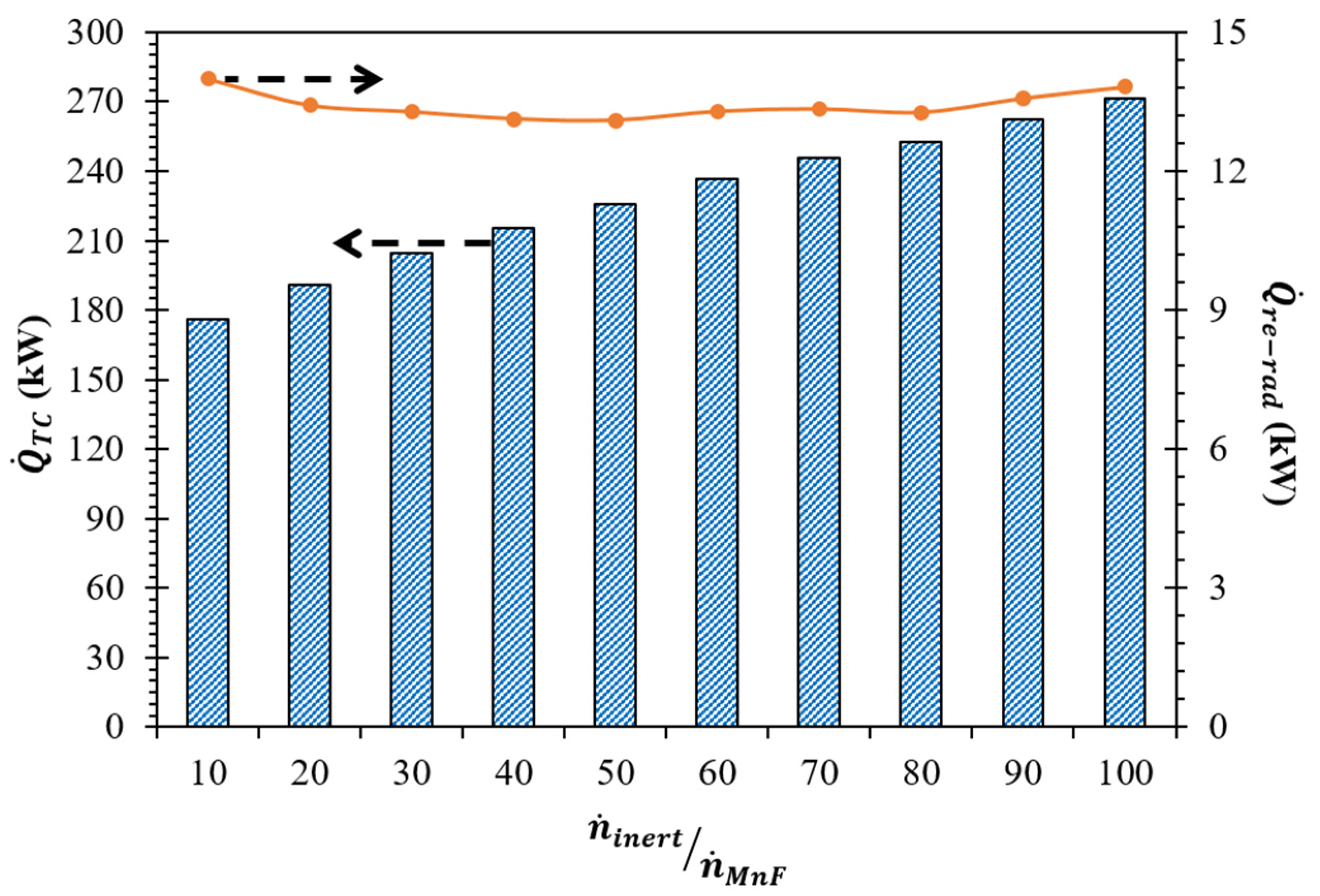
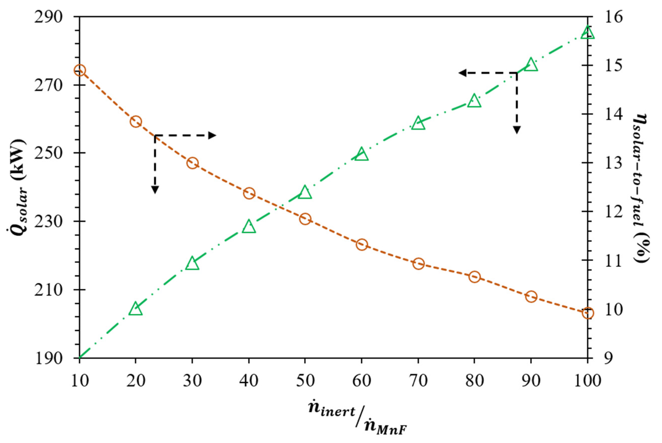
3. Results and Discussion
4. Conclusions
Author Contributions
Funding
Data Availability Statement
Acknowledgments
Conflicts of Interest
Nomenclature
| C | Solar flux concentration ratio, suns |
| Higher heating value of CO, kW | |
| HEX-1 | Heat exchanger-1 |
| HEX-2 | Heat exchanger-2 |
| HEX-3 | Heat exchanger-3 |
| HEX-4 | Heat exchanger-4 |
| HEX-5 | Heat exchanger-5 |
| I | Normal beam solar insolation, W/m2 |
| MO | Metal oxide |
| Molar amount, mol | |
| Molar amount of CO at state , mol | |
| Molar amount of CO at state , mol | |
| Molar amount of O2 at state , mol | |
| Molar amount of O2 at state , mol | |
| Molar flow rate, mol/s | |
| Molar flow rate of inert, mol/s | |
| Molar flow rate of , mol/s | |
| Ratio of molar flow rates of inert to | |
| Molar flow rate of CO2, mol/s | |
| Molar flow rate of CO, mol/s | |
| Molar flow rate of O2, mol/s | |
| Thermal energy required to heat inert sweep gas, kW | |
| Thermal energy released during cooling of inert + O2 gas mixture, kW | |
| Thermal energy released during cooling of CO2 + CO gas mixture, kW | |
| Thermal energy released during cooling of CO2, kW | |
| Thermal energy required to heat CO2, kW | |
| Auxiliary thermal energy required to heat inert sweep gas, kW | |
| Auxiliary thermal energy required to heat CO2, kW | |
| Thermal energy released during cooling of O2, kW | |
| Solar energy required to run the cycle, kW | |
| Thermal energy required for the operation of separator-1, kW | |
| Thermal energy required for the operation of separator-2, kW | |
| Thermal energy losses over the reduction chamber walls, kW | |
| Thermal energy required to run the cycle, Kw | |
| Thermal energy required for thermal reduction of , kW | |
| Thermal energy required to heat the , kW | |
| Thermal energy released during re-oxidation of , kW | |
| Re-radiation losses from the cycle, kW | |
| Ideal gas constant (8.314 J/mol·K) | |
| Ambient temperature, K | |
| Oxidation (splitting) temperature, K | |
| Reduction temperature, K | |
| Operating temperature of separator-1, K | |
| Operating temperature of separator-2, K | |
| Mol fraction of CO at state , mol | |
| Mol fraction of CO at state , mol | |
| Mol fraction of O2 at state , mol | |
| Mol fraction of O2 at state , mol | |
| Solar energy absorption efficiency, % | |
| Efficiency of separator-1, % | |
| Efficiency of separator-2, % | |
| Solar-to-fuel energy conversion efficiency, % | |
| Reduction nonstiochiometry | |
| Gas-to-gas heat recovery effectiveness | |
| Solid-to-solid heat recovery effectiveness | |
| Stefan–Boltzmann constant, 5.670 × 10⁻⁸ (W/m2·K4) |
References
- Bhosale, R.R.; Mahajani, V.V. Kinetics of Absorption of Carbon Dioxide in Aqueous Solution of Ethylaminoethanol Modified with N-methyl-2-pyrolidone. Sep. Sci. Technol. 2013, 48, 2324–2337. [Google Scholar] [CrossRef]
- Carrillo, R.J.; Scheffe, J.R. Advances and trends in redox materials for solar thermochemical fuel production. Sol. Energy 2017, 156, 3–20. [Google Scholar] [CrossRef]
- Almomani, F.; Bhosale, R.; Khraisheh, M.; Kumar, A.; Tawalbeh, M. Photocatalytic conversion of CO2 and H2O to useful fuels by nanostructured composite catalysis. Appl. Surf. Sci. 2019, 483, 363–372. [Google Scholar] [CrossRef]
- Gomez Vidales, A.; Semai, M. Platinum nanoparticles supported on nickel-molybdenum-oxide for efficient hydrogen production via acidic water electrolysis. J. Mol. Struct. 2023, 1290, 135956. [Google Scholar] [CrossRef]
- Koepf, E.; Villasmil, W.; Meier, A. Pilot-scale solar reactor operation and characterization for fuel production via the Zn/ZnO thermochemical cycle. Appl. Energy 2016, 165, 1004–1023. [Google Scholar] [CrossRef]
- Bhosale, R.R. Thermodynamic efficiency analysis of zinc oxide based solar driven thermochemical H2O splitting cycle: Effect of partial pressure of O2, thermal reduction and H2O splitting temperatures. Int. J. Hydrog. Energy 2018, 43, 14915–14924. [Google Scholar] [CrossRef]
- Abanades, S.; Charvin, P.; Lemont, F.; Flamant, G. Novel two-step SnO2/SnO water-splitting cycle for solar thermochemical production of hydrogen. Int. J. Hydrog. Energy 2008, 33, 6021–6030. [Google Scholar] [CrossRef]
- Bhosale, R.R.; Shende, R.V.; Gupta, R.B. SnO2/SnO based redox thermochemical CO2 splitting cycle: Effect of inert gas flowrate, reduction temperature, and gas separation on the solar-to-fuel energy conversion efficiency. Int. J. Energy Res. 2022, 46, 9267–9280. [Google Scholar] [CrossRef]
- Kodama, T.; Nakamuro, Y.; Mizuno, T. A two-step thermochemical water splitting by iron-oxide on stabilized zirconia. J. Sol. Energy Eng. Trans. ASME 2006, 128, 3–7. [Google Scholar] [CrossRef]
- Bhosale, R.R.; Kumar, A.; AlMomani, F.; Ghosh, U.; Sutar, P.; Takalkar, G.; Ashok, A.; Alxneit, I. Effectiveness of Ni incorporation in iron oxide crystal structure towards thermochemical CO2 splitting reaction. Ceram. Int. 2017, 43, 5150–5155. [Google Scholar] [CrossRef]
- Kaneko, H.; Gokon, N.; Hasegawa, N.; Tamaura, Y. Solar thermochemical process for hydrogen production using ferrites. Energy 2005, 30, 2171–2178. [Google Scholar] [CrossRef]
- Bhosale, R.R.; Kumar, A.; AlMomani, F.; Alxneit, I. Propylene oxide assisted sol–gel synthesis of zinc ferrite nanoparticles for solar fuel production. Ceram. Int. 2016, 42, 2431–2438. [Google Scholar] [CrossRef]
- Bulfin, B.; Call, F.; Lange, M.; Lübben, O.; Sattler, C.; Pitz-Paal, R.; Shvets, I.V. Thermodynamics of CeO2 thermochemical fuel production. Energy Fuels 2015, 29, 1001–1009. [Google Scholar] [CrossRef]
- Bhosale, R.R.; Takalkar, G. Nanostructured co-precipitated Ce0.9Ln0.1O2 (Ln= La, Pr, Sm, Nd, Gd, Tb, Dy, or Er) for thermochemical conversion of CO2. Ceram. Int. 2018, 44, 16688–16697. [Google Scholar] [CrossRef]
- Takalkar, G.; Bhosale, R.R.; AlMomani, F. Thermochemical splitting of CO2 using Co-precipitation synthesized Ce0.75Zr0.2M0.05O2-Δ (M = Cr, Mn, Fe, CO, Ni, Zn) materials. Fuel 2019, 256, 115834. [Google Scholar] [CrossRef]
- Furler, P.; Scheffe, J.; Gorbar, M.; Moes, L.; Vogt, U.; Steinfeld, A. Solar Thermochemical CO2 Splitting Utilizing a Reticulated Porous Ceria Redox System. Energy Fuels 2012, 26, 7051–7059. [Google Scholar] [CrossRef]
- Dey, S.; Naidu, B.S.; Rao, C.N.R. Ln0.5A0.5MnO3 (Ln = Lanthanide, A = Ca, Sr) perovskites exhibiting remarkable performance in the thermochemical generation of CO and H2 from CO2 and H2O. Chem. A Eur. J. 2015, 21, 7077–7081. [Google Scholar] [CrossRef]
- Takalkar, G.; Bhosale, R.; AlMomani, F. Combustion synthesized A0.5Sr0.5MnO3-δ perovskites (where, A = La, Nd, Sm, Gd, Tb, Pr, Dy, and Y) as redox materials for thermochemical splitting of CO2. Appl. Surf. Sci. 2019, 489, 80–91. [Google Scholar] [CrossRef]
- Bhosale, R.R.; Kumar, A.; AlMomani, F.; Ghosh, U.; Dardor, D.; Bouabidi, Z.; Ali, M.; Yousefi, S.; AlNouss, A.; Anis, M.S.; et al. Solar co-production of samarium and syngas via methanothermal reduction of samarium sesquioxide. Energy Convers. Manag. 2016, 112, 413–422. [Google Scholar] [CrossRef]
- Bhosale, R.R.; Sutar, P.; Kumar, A.; AlMomani, F.; Ali, M.H.; Ghosh, U.; AlMuhtaseb, S.; Khraisheh, M. Solar hydrogen production via erbium oxide based thermochemical water splitting cycle. J. Renew. Sustain. Energy 2016, 8, 34702. [Google Scholar] [CrossRef]
- Bhosale, R.R. Thermodynamic analysis of Ni-ferrite based solar thermochemical H2O splitting cycle for H2 production. Int. J. Hydrog. Energy 2019, 44, 61–71. [Google Scholar] [CrossRef]
- Scheffe, J.R.; Li, J.; Weimer, A.W. A spinel ferrite/hercynite water-splitting redox cycle. Int. J. Hydrog. Energy 2010, 35, 3333–3340. [Google Scholar] [CrossRef]
- Tamaura, Y.; Kojima, N.; Hasegawa, N.; Inoue, M.; Uehara, R.; Gokon, N.; Kaneko, H. Stoichiometric studies of H2 generation reaction for H2O/Zn/Fe3O4 system. Int. J. Hydrog. Energy 2001, 26, 917–922. [Google Scholar] [CrossRef]
- Bhosale, R.; Khadka, R.; Puszynski, J.; Shende, R. H2 generation from two-step thermochemical water-splitting reaction using sol-gel derived SnxFeyOz. J. Renew. Sustain. Energy 2011, 3, 63104. [Google Scholar] [CrossRef]
- Randhir, K.; Rhodes, N.R.; Li, L.; AuYeung, N.; Hahn, D.W.; Mei, R.; Klausner, J.F. Magnesioferrites for solar thermochemical fuel production. Sol. Energy 2018, 163, 1–15. [Google Scholar] [CrossRef]
- Fresno, F.; Fernández-Saavedra, R.; Belén Gómez-Mancebo, M.; Vidal, A.; Sánchez, M.; Isabel Rucandio, M.; Quejido, A.J.; Romero, M. Solar hydrogen production by two-step thermochemical cycles: Evaluation of the activity of commercial ferrites. Int. J. Hydrog. Energy 2009, 34, 2918–2924. [Google Scholar] [CrossRef]
- Takalkar, G.; Bhosale, R.R.; AlMomani, F.; Rashid, S.; Shakoor, R.A. Ni incorporation in MgFe2O4 for improved CO2-splitting activity during solar fuel production. J. Mater. Sci. 2020, 55, 11086–11094. [Google Scholar] [CrossRef]
- Inoue, M.; Hasegawa, N.; Uehara, R.; Gokon, N.; Kaneko, H.; Tamaura, Y. Solar hydrogen generation with H2O/ZnO/MnFe2O4 system. Sol. Energy 2004, 76, 309–315. [Google Scholar] [CrossRef]
- Padella, F.; Alvani, C.; Barbera ALa Ennas, G.; Liberatore, R.; Varsano, F. Mechanosynthesis and process characterization of nanostructured manganese ferrite. Mater. Chem. Phys. 2005, 90, 172–177. [Google Scholar] [CrossRef]
- Alvani, C.; Ennas, G.; Labarbera, A.; Marongiu, G.; Padella, F.; Varsano, F. Synthesis and characterization of nanocrystalline: Advances in thermochemical water splitting. Int. J. Hydrog. Energy 2005, 30, 1407–1411. [Google Scholar] [CrossRef]
- Go, K.; Son, S.; Kim, S. Reaction kinetics of reduction and oxidation of metal oxides for hydrogen production. Int. J. Hydrog. Energy 2008, 33, 5986–5995. [Google Scholar] [CrossRef]
- Tamaura, Y.; Hasegawa, N.; Kojima, M.; Ueda, Y.; Amano, H.; Tsuji, M. Water splitting with the Mn(II)-ferrite–CaO–H2O system at 1273K. Energy 1998, 23, 879–886. [Google Scholar] [CrossRef]
- Ehrensberger, K. Temporary phase segregation processes during the oxidation of (Fe0.7Mn0.3)0.99O in N2_H2O atmosphere. Solid. State Ion. 1996, 90, 75–81. [Google Scholar] [CrossRef]
- Bhosale, R.R.; Shende, R.V.; Puszynski, J.A. Thermochemical water-splitting for H2 generation using sol-gel derived Mn-ferrite in a packed bed reactor. Int. J. Hydrog. Energy 2012, 37, 2924–2934. [Google Scholar] [CrossRef]
- Bhosale, R.R. Mn-ferrite based solar thermochemical water splitting cycle: A thermodynamic evaluation. Fuel 2019, 256, 115847. [Google Scholar] [CrossRef]
- Ehrhart, B.D.; Muhich, C.L.; Al-Shankiti, I.; Weimer, A.W. System efficiency for two-step metal oxide solar thermochemical hydrogen production—Part 1: Thermodynamic model and impact of oxidation kinetics. Int. J. Hydrog. Energy 2016, 41, 19881–19893. [Google Scholar] [CrossRef]
- Carrillo, R.J.; Scheffe, J.R. Beyond Ceria: Theoretical Investigation of Isothermal and Near-Isothermal Redox Cycling of Perovskites for Solar Thermochemical Fuel Production. Energy Fuels 2019, 33, 12871–12884. [Google Scholar] [CrossRef]
- Anderson, L.L.; Armstrong, P.A.; Broekhuis, R.R.; Carolan, M.F.; Chen, J.; Hutcheon, M.D.; Lewinsohn, C.A.; Miller, C.F.; Repasky, J.M.; Taylor, D.M.; et al. Advances in ion transport membrane technology for oxygen and syngas production. Solid. State Ion. 2016, 288, 331–337. [Google Scholar] [CrossRef] [Green Version]
- Lu, Y.; Zhu, L.; Agrafiotis, C.; Vieten, J.; Roeb, M.; Sattler, C. Solar fuels production: Two-step thermochemical cycles with cerium-based oxides. Prog. Energy Combust. Sci. 2019, 75, 100785. [Google Scholar] [CrossRef]
- Bhosale, R.R.; Shende, R.V.; Gupta, R.B. Application of Zn-ferrite towards thermochemical utilization of carbon dioxide: A thermodynamic investigation. Energy Convers. Manag. 2021, 245, 114528. [Google Scholar] [CrossRef]


(K) | (kW) | Required | |||
|---|---|---|---|---|---|
| After HEX-2 (kW) | After HEX-3 (kW) | After HEX-4 (kW) | |||
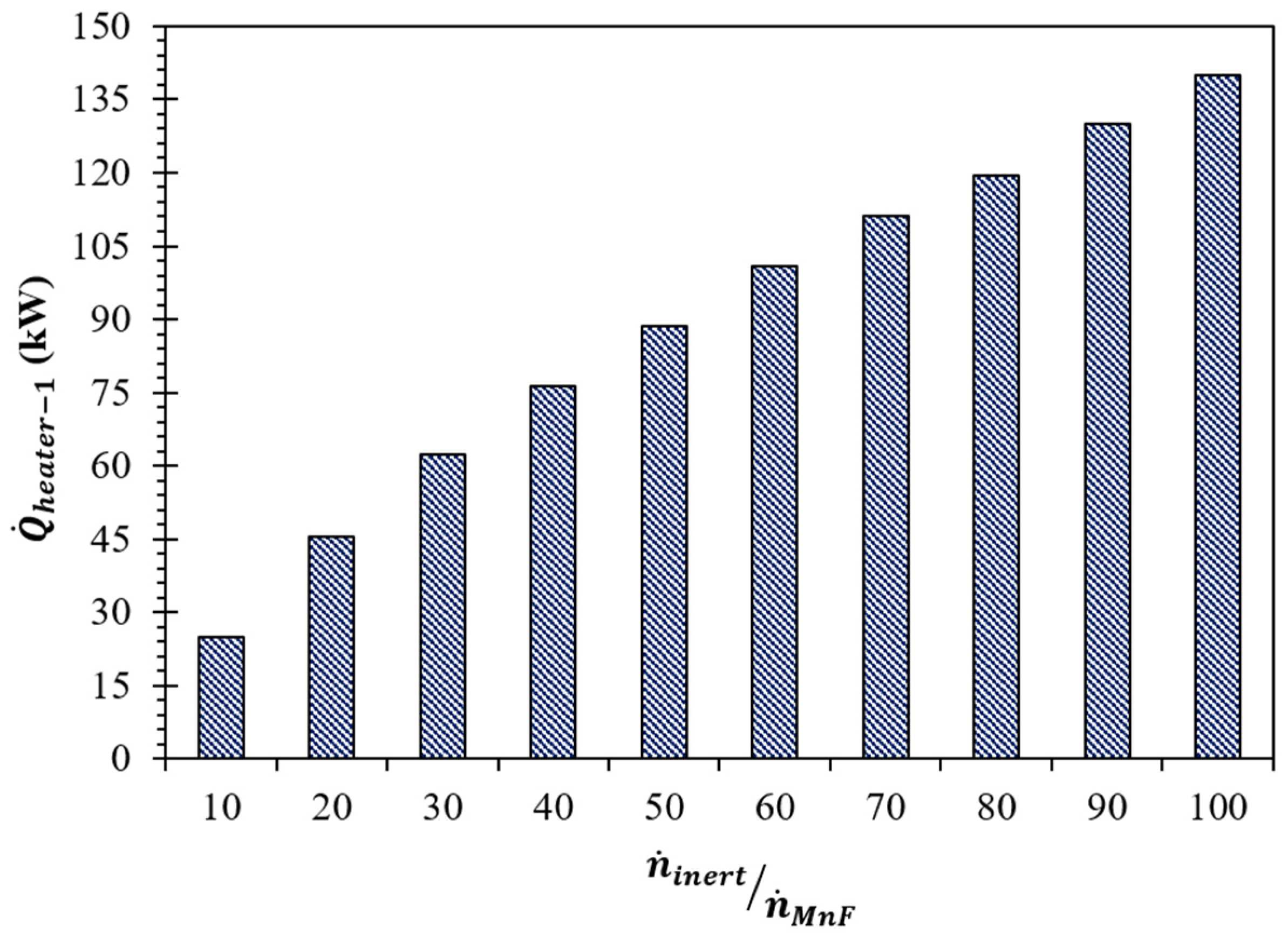
| 10 | 1405 | 95.8 | 28.4 | 27.5 | 24.9 |
| 20 | 1365 | 164.1 | 48.9 | 48.0 | 45.5 |
| 30 | 1340 | 220.4 | 65.8 | 64.9 | 62.4 |
| 40 | 1320 | 266.4 | 79.7 | 78.7 | 76.2 |
| 50 | 1305 | 307.4 | 92.0 | 91.0 | 88.5 |
| 60 | 1295 | 348.4 | 104.3 | 103.3 | 100.8 |
| 70 | 1285 | 382.6 | 114.6 | 113.6 | 111.1 |
| 80 | 1275 | 409.9 | 122.8 | 121.8 | 119.3 |
| 90 | 1270 | 445.9 | 133.6 | 132.6 | 130.1 |
| 100 | 1265 | 478.4 | 143.3 | 142.4 | 139.9 |
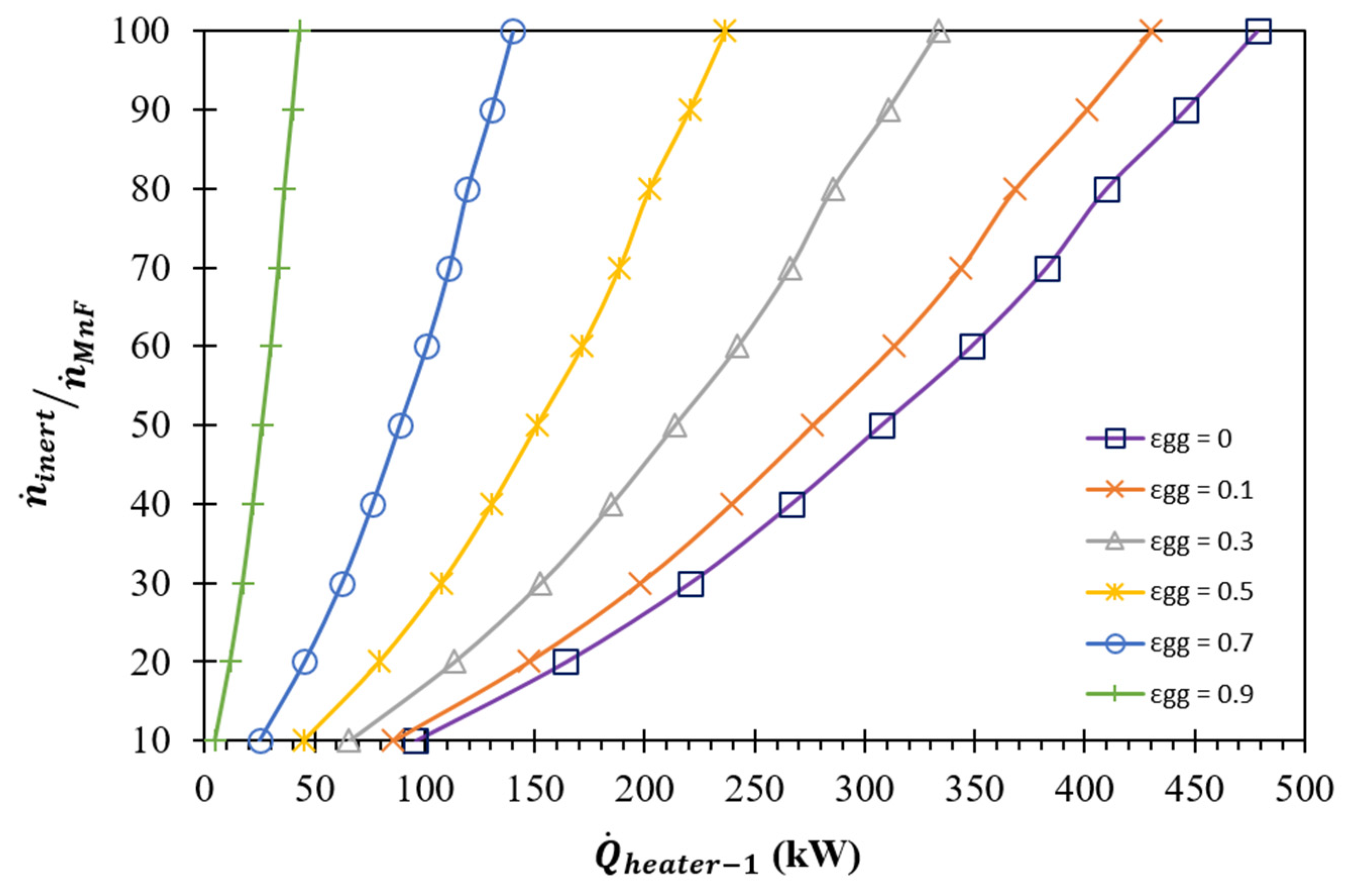
| (kW) | |
|---|---|
| 0.0 | 33.4 |
| 0.1 | 30.6 |
| 0.3 | 24.9 |
| 0.5 | 19.2 |
| 0.7 | 13.6 |
| 0.9 | 7.9 |
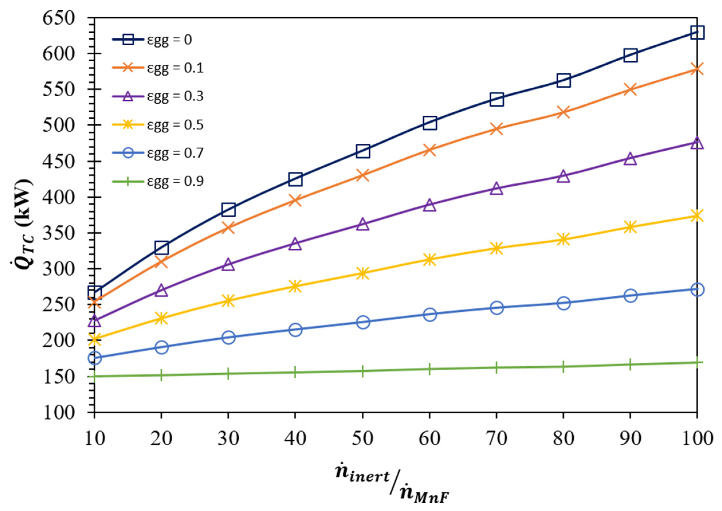
| (K) | (kW) | ||||||
|---|---|---|---|---|---|---|---|
| = 0.0 | = 0.1 | = 0.3 | = 0.5 | = 0.7 | = 0.9 | ||
| 10 | 1405 | 288.0 | 274.0 | 246.0 | 218.0 | 190.0 | 162.0 |
| 20 | 1365 | 352.7 | 331.6 | 289.2 | 246.9 | 204.5 | 162.2 |
| 30 | 1340 | 407.2 | 380.2 | 326.1 | 272.0 | 217.8 | 163.7 |
| 40 | 1320 | 451.5 | 419.7 | 356.0 | 292.3 | 228.7 | 165.0 |
| 50 | 1305 | 491.4 | 455.3 | 383.1 | 311.0 | 238.8 | 166.6 |
| 60 | 1295 | 532.4 | 492.0 | 411.3 | 330.6 | 250.0 | 169.3 |
| 70 | 1285 | 566.0 | 522.1 | 434.4 | 346.6 | 258.9 | 171.1 |
| 80 | 1275 | 592.3 | 545.6 | 452.3 | 358.9 | 265.6 | 172.2 |
| 90 | 1270 | 629.0 | 578.6 | 477.8 | 376.9 | 276.1 | 175.2 |
| 100 | 1265 | 662.1 | 608.3 | 500.7 | 393.1 | 285.5 | 177.9 |
Disclaimer/Publisher’s Note: The statements, opinions and data contained in all publications are solely those of the individual author(s) and contributor(s) and not of MDPI and/or the editor(s). MDPI and/or the editor(s) disclaim responsibility for any injury to people or property resulting from any ideas, methods, instructions or products referred to in the content. |
© 2023 by the authors. Licensee MDPI, Basel, Switzerland. This article is an open access article distributed under the terms and conditions of the Creative Commons Attribution (CC BY) license (https://creativecommons.org/licenses/by/4.0/).
Share and Cite
Bhosale, R.R.; Akhter, S.; Gupta, R.B.; Shende, R.V. Utilization of MnFe2O4 Redox Ferrite for Solar Fuel Production via CO2 Splitting: A Thermodynamic Study. Energies 2023, 16, 5479. https://doi.org/10.3390/en16145479
Bhosale RR, Akhter S, Gupta RB, Shende RV. Utilization of MnFe2O4 Redox Ferrite for Solar Fuel Production via CO2 Splitting: A Thermodynamic Study. Energies. 2023; 16(14):5479. https://doi.org/10.3390/en16145479
Chicago/Turabian StyleBhosale, Rahul R., Sayma Akhter, Ram B. Gupta, and Rajesh V. Shende. 2023. "Utilization of MnFe2O4 Redox Ferrite for Solar Fuel Production via CO2 Splitting: A Thermodynamic Study" Energies 16, no. 14: 5479. https://doi.org/10.3390/en16145479
APA StyleBhosale, R. R., Akhter, S., Gupta, R. B., & Shende, R. V. (2023). Utilization of MnFe2O4 Redox Ferrite for Solar Fuel Production via CO2 Splitting: A Thermodynamic Study. Energies, 16(14), 5479. https://doi.org/10.3390/en16145479