Article

Effects of Reservoir Heterogeneity on CO2 Dissolution Efficiency in Randomly Multilayered Formations

1
Southern Marine Science and Engineering Guangdong Laboratory (Zhanjiang), Zhanjiang 524006, China
2
Department of Petroleum Geology & Geology, School of Geosciences, University of Aberdeen, Aberdeen AB24 3UE, UK
3
State Key Laboratory of Geomechanics and Geotechnical Engineering, Institute of Rock and Soil Mechanics, Chinese Academy of Sciences, Wuhan 430071, China
4
Shenzhen Key Laboratory of Deep Engineering Sciences and Green Energy, College of Civil and Transportation Engineering, Shenzhen University, Shenzhen 518060, China
5
School of Mechatronic Engineering, Southwest Petroleum University, Chengdu 610500, China
*
Author to whom correspondence should be addressed.
Energies 2023, 16(13), 5219; https://doi.org/10.3390/en16135219
Submission received: 25 May 2023 / Revised: 27 June 2023 / Accepted: 29 June 2023 / Published: 7 July 2023
(This article belongs to the Special Issue Potential Evaluation of CO2 EOR and Storage in Oilfields)

Abstract

:
Carbon dioxide (CO2) dissolution is the secondary trapping mechanism enhancing the long-term security of CO2 in confined geological formations. CO2 injected into a randomly multilayered formation will preferentially migrate along high permeability layers, increasing CO2 dissolution efficiency. In this study, sequential Gaussian simulation is adopted to construct the stratified saline formations, and two-phase flow based on MRST is established to illustrate the spatial mobility and distribution of CO2 migration. The results show that gravity index G and permeability heterogeneity σ Y 2 are the two predominant factors controlling the spatial mobility and distribution of CO2 transports. The CO2 migration shows a totally different spatial mobility under different gravity index and heterogeneity. When the permeability discrepancy is relatively larger, CO2 preferentially migrates along the horizontal layer without accompanying the vertical migration. For the formation controlled by gravity index, CO2 migration is governed by supercritical gaseous characteristics. For the medium gravity index, the upward and lateral flow characteristics of the CO2 plume is determined by gravity index and heterogeneity. When the gravity index is smaller, permeability heterogeneity is the key factor influencing CO2 plume characteristics. Permeability heterogeneity is the decisive factor in determining final CO2 dissolution efficiency. This investigation of CO2 mobility in randomly multilayered reservoirs provides an effective reference for CO2 storage.

1. Introduction

Global warming is the greatest existential challenge facing humanity according to the Intergovernmental Panel on Climate Change (IPCC) Report [1]. Global warming may threaten human life security and social sustainable development [2]. Geological carbon sequestration is an effective measure against global climate change since it can mitigate climate impacts and reduce greenhouse gas emission [3,4]. Saline aquifers in deep geological formations are predominantly candidates for geological CO2 sequestration given their hydrodynamic, geological, and thermal conditions [5,6]. It is estimated that geological reservoirs have a potential storage capacity between 8000 and 55,000 Gt of CO2, representing a sufficient capacity to store over 200 years of current carbon dioxide emissions [7,8].
CO2 is in supercritical state when injected into saline aquifers (the pressure and temperature of supercritical CO2 are 7.382 MPa and 31.048 °C, respectively) [9]. CO2 trapping mechanisms are mainly as follows: stratigraphic or structural, solubility, residual, and mineral trapping [10,11,12,13,14]. For structural trapping, supercritical carbon dioxide is confined as a buoyant immiscible phase within the reservoir, restrained by the structure and the seal rock. Due to residual pressure or capillary pressure, the immobilization of CO2 occupies the small pores of the saline aquifer during CO2 injection [15,16,17]. The fluid–rock interaction of the aquifers results in solubility trapping, reducing the amount of mobile CO2 lying below the cap rock and ensuring the long-term security of CO2 storage [18]. Furthermore, mineral trapping is considered to be the result of rock-fluid-CO2 interaction, involving the geochemistry reactions of reservoir minerals such as calcite, dolomite, siderite, etc. Mineral trapping is the slowest but the most permanent and most safe process [19,20,21,22].
For CO2 dissolution trapping mechanisms, CO2 dissolution efficiency due to rock-fluid-CO2 interaction is controlled by reservoir heterogeneity on all scales [23,24]. Many previous studies have extensively investigated the effect of the geological heterogeneity on CO2 trapping by experiment, field data and numeral simulation. Kim et al. [25] carried out Darcy-scale multiphase flow experiments on a heterogeneous specimen to obtain CO2 saturation during both drainage and imbibition. Sohal et al. [26] studied the effect of heterogeneous wettability distribution on CO2 storage efficiency, which showed that both heterogeneously distributed wettability and higher temperature accelerated the vertical CO2 migration significantly and reduced storage capacity. Singh et al. [27] investigated CO2 dissolution and local capillary trapping in permeability and capillary heterogeneous reservoir, which suggested that vertical distance between the centers of mass of the supercritical CO2 and dissolved CO2 plumes is larger for heterogeneous reservoirs. Onoja et al. [28] investigated the relevance of representing relative permeability variations in the sealing formation, the results demonstrate that gradational changes at the base of the caprock could influence the pressure changes propagating vertically into the caprock from the saline aquifer. Mouche et al. [29] presented an upscaled model for the vertical migration of the CO2 plume, the results illustrate that the upscaled saturation is controlled by the capillary pressure at the interface of the connected layers. Green et al. [30] studied the heterogeneity effect of vertical permeability on CO2 long-term migration and showed that the heterogeneous formation with equivalent effective vertical permeability has a shorter breakthrough time in saline aquifer. Deng et al. [31] investigated the effect of multi-scale heterogeneity on storage capacity, designs of injection wells, injection rate, CO2 plume migration, and CO2 potential leakage. Kim et al. [32] and Paiman et al. [33] investigated the fracture heterogeneity, and revealed that fractures can significantly affect the predicted amount of trapped CO2. Galkin et al. [34] adopted X-ray tomography and electron microscopy for description of rock pore space considering reservoir heterogeneity, considered to be an important method to introduce new methods for the development of complex reservoirs. Martyushev et al. [35,36,37,38] modified the geological and hydrodynamic model considering both horizontal and vertical permeability heterogeneities (anisotropy parameter), significantly improving the adaptation of both injection and production wells. Oh et al. [39] researched the injection-induced pressure and buoyancy force in a horizontally and vertically stratified core utilizing a core-flooding system with a 2-D X-ray scanner, concluding that CO2 movement was primarily controlled by media heterogeneity. Rasmusson et al. [40] constructed strata alternating high and low permeability to investigate CO2 migration, considering the coupled wellbore-reservoir flow. Although several studies have investigated the effect of heterogeneity on CO2 migration, there are very limited researches regarding qualitative analysis of CO2 dissolution efficiency considering small-scale variability in stratification permeability during GCS.
The main objective of this investigation aims to reveal the effect of permeability heterogeneity on CO2 dissolution efficiency in reservoir-caprock system. The two-phase flow model is implemented in MRST (Matlab Reservoir Simulation Toolbox) [41], a finite-volume based method. It is very convenient to develop new features within MRST. The two-phase flow involves the dissolution of CO2 into brine and evaporation of H2O into the CO2 gaseous state. Mathematical description and model implementation of the simulation model are illustrated in Section 2 and Section 3, respectively. Model validation and sensitive analysis of the CO2 dissolution efficiency are depicted in Section 4. Finally, the conclusions are summarized in Section 5.

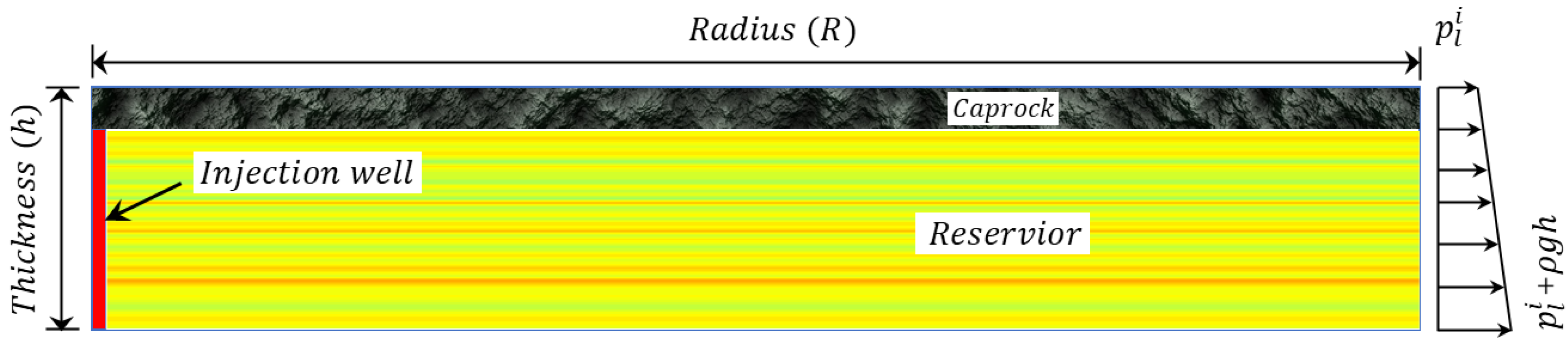
2. Mathematical Model

2.1. Extended Reaction System

There are three chemical components (CO2, H2O, NaCl) in the geological system. The chemical species is determined by the following equilibrium chemical reactions [42,43]:
H 2 O l H 2 O g ,   K H = f g H / a l H
C O 2 a q C O 2 g ,   K C = f g C / a l C
where K H and K C are the equilibrium constants for H2O and CO2, respectively; f g α and a l α represent the fugacity and activity of the α component in gas or liquid state.
The equilibrium constants of CO2 and H2O relation equations are expressed as:
K β = K β 0 e x p p l p 0 V β R T c
with
K β 0 = 10 a β + b β T c + c β T c 2 + d β T c 3
where R = 8.314 [J · K−1 · mol−1] is a universal gas constant; T c is the temperature in °C; V β is the mean molar volume of the pure condensed species when pressure changes from p 0 to p l ; a β , b β , c β and d β are the equation parameters.
When the chemical reaction is at equilibrium, the mole fractions of H2O in gas x g H and CO2 in liquid x l C are illustrated in Equations (3) and (4).
x g H = K H a l H F H P t o t
x l C = F C 1 x g H P t o t 55.508 r c o 2 K C
where F H and F C the fugacity coefficients of H2O and CO2 in CO2-rich phase; P t o t is the total pressure; r c o 2 is the activity coefficient that illustrates the relation between the solubility of aqueous CO2 in pure water and brine.
The mutual solubilities can be expressed in the following formula:
x g H = 1 B x l S 1 A B
x l C = B 1 x g H
A = K H F H P t o t
B = F C P t o t 55.508 r c o 2 K C
Mass fractions of H2O in gas phase ( X g H ) and aqueous CO2 in liquid brine phase ( X l C ) can be obtained in a concise formula [44]:
X g H = 18.015 x g H 18.015 x g H + 44.01 1 x g H
X l C = 44.01 x l C 18.015 1 x l C 1 + 0.05844 m l S + 44.01 x l C
where m l S denotes the molality of NaCl in liquid state.

2.2. Mass Transport Equations

Based on the mass balances of the H and C components in the geological system, the component transport equations are given as:
α = l , g φ S α ρ α X α H t + · X α H ρ α q α · φ S α ρ α D α X α H Q g H = 0
α = l , g φ S α ρ α X α C t + · X α C ρ α q α · φ S α ρ α D α X α C Q g C = 0
where α = l and α = g represent the liquid brine and gaseous CO2-rich phase; φ is the reservoir porosity; S α is the saturation of the α -phase; ρ α is the density of the α -phase (kg / m3); X α H and X α C indicate the mass fraction of H and C components in the α -phase; D α is the dispersion tensor (m2 · s−1); Q g H and Q g C are the source term (kg · s−1); q α is the fluid flux of the α -phase associated with Darcy’s velocity:
q α = κ k r α μ α p α ρ g g z
where κ is the intrinsic permeability (m2); k r α is the relative permeability of the α -phase; μ α is the viscosity (pa · s); p α is the fluid pressure (pa); g is the gravitational acceleration (m · s−2); z is the vertical distance (m).

2.3. Constitutive Equation

To set up the multiphase flow simulation, we need the capillary-saturation relationship P c S w . Flooding experiments on core samples from the reservoir are used to develop the empirical relationship between P c and S w . Leverett J-function is adopted to normalize the measured data [45,46,47,48]:
J S w = p c σ cos θ K φ
where σ is the surface tension measured in the laboratory; θ is the contact angle; K / φ is scaling factor proportional to the radius of pore-throat.
Van Genuchten model for the retention curve is used to express the effective liquid saturation of the brine system [49]:
S l p c = 1 , p c < 0 1 + k φ ¯ k g φ α p p c n p m p ,   p c 0
where S l is the effective saturation; φ ¯ and k g are the mean porosity and mean permeability of the reservoir, respectively; α p is the scaling parameter for the retention curve.
The relative permeabilities for the liquid and gas phases can be expressed as follows:
k r l = k r l m · S l ϵ p 1 1 S l 1 / m p m p 2
k r g = k r g m · 1 S l γ p 1 S l 1 / m p 2 m p
where k r l m , k r g m , ϵ p and γ p are the scaling parameters, the values of the main parameters are as shown in Table 1.

3. Numerical Implementation

Newton-Raphson Iteration

Liquid pressure ( p l ), gas pressure ( p g ) and bottom hole pressure ( p b h ) are chosen as the independent variables during the numerical implementation. Newton-Raphson iteration method is adopted to solve the governing equations. The system of three equations is expressed in compact form:
F x = 0
where
F = F H F C F W ,   x = p l p g p b h
where F H , F C and F W represent the equilibrium control equations for H2O, CO2 and injection wells.
The Newton-Raphson iteration of x is expressed as:
J t i + 1 , k δ x i + 1 , k = F t i + 1 , k
where the Jacobian matrix is:
J t i + 1 , k = F H p l F H p g F H p b h F C p l F C p g F C p b h F W p l F W p g F W p b h i + 1 , k
Taylor series is used to update the independent variables:
x i + 1 , k + 1 = x i + 1 , k + δ x i + 1 , k

4. Numerical Simulation

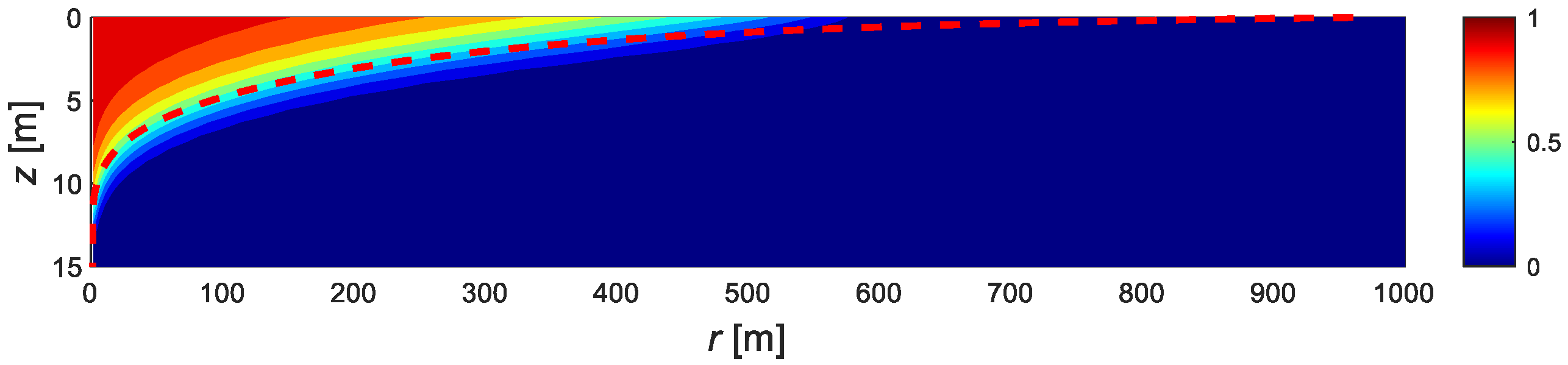
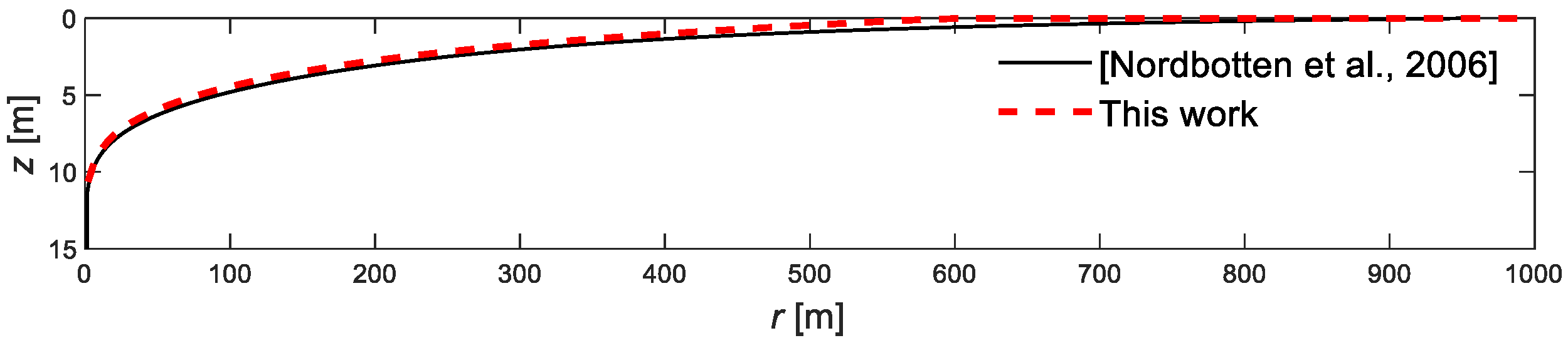
4.1. Model Validation

In order to validate the accuracy of the numerical method, the sharp interface is achieved by moving all of the gaseous CO2 above the liquid brine, and the plume depth of the interface is given:
z r = 0 h S g r , z d z
Figure 1 and Figure 2 show saturation distribution of the gas phase and the comparison of the numerical result with the similarity solution of CO2 injection in homogenous formation by Nordbotten. Nordbotten et al. [50] derived the similarity solution of carbon dioxide injected into confined aquifers, assuming that a clear interface separates the gaseous CO2 and brine liquid, as illustrated in Figure 2.

4.2. Effect of Pressure

The problem of interest here is the injection of supercritical CO2 through a fully penetrating vertical well beneath the caprock in the deep confined saline aquifer. Sequential Gaussian simulation (SGSIM) as a stochastic method has been developed to generate a series of models of possible reservoir rock heterogeneities [51]. This simulation technique produces equiprobable models of a continuous variable with the appropriate probability distribution and a spatial correlation function. The simplicity and flexibility of the SGSIM code make it particularly appropriate for simulating petrophysical properties such as permeabilities and porosities of the reservoir. The multilayered reservoir is composed of horizontally stratified layers with the sequential Gaussian simulation method by SGSIM code. The permeability is represented by the spatial variability of the intrinsic permeability, and the permeability is rescaled to obtain the reservoir statical property as follows:
Y x = Y ¯ + σ Y Y s t d x
where Y ¯ is the intrinsic permeability of the reservoir; σ Y is the sqrt of variance σ Y 2 , indicating the heterogeneity coefficient of saline aquifers; and Y s t d x is the standardized Gaussian random field with a zero mean and unit variance.
There are two immiscible fluid phases, namely the water-rich brine phase and the CO2-rich gaseous phase. The brine phase is mainly represented by a high-concentration of NaCl in water. The temperature is considered to be constant during CO2 injection. The simulation system is represented by an axisymmetric model in the cylindrical system ( r , φ , z ).
The multilayered formation system is initially saturated with the brine in a hydrostatic state, and the top and bottom boundaries are impermeable boundaries. The liquid pressure at the right boundary increases downward with a vertical gradient. Schematic of the simulation setup is shown in Figure 3. Logarithm permeability distributions of the reservoir beneath the caprock with three different variances σ Y 2 are illustrated in Figure 4. The specified values of logarithm permeability distributions along the reservoir depth are shown in Figure 5. The larger the variance is, the more heterogeneous the multilayered formation is. The parameters listed in adopted for GCS are illustrated in Table 2.
Gravity index G is defined as the ratio of gravity force resulting from vertical permeability, density difference, and reservoir thickness to the viscose force:
G = 2 π ρ l ρ g ρ g g k h h 2 Q μ l
where ρ l and ρ g are the density of the brine liquid and supercritical gaseous phases; k h is the vertical permeability of the reservoir; h is the vertical thickness of the formation; and Q is the injection rate of the gas phase.
The parameters listed in Table 3 includes different values of injection rate Q , variances σ Y 2 and gravity index G . Note that gravity index G and variances σ Y 2 are dimensionless.

4.3. Spatial Mobility and Distribution of CO2

Effective gas saturation S g e is adopted to interpret the CO2 plume evolution during CO2 injection:
S g e = S g S g r 1 S l r S g r
where S l r and S g r are the residual liquid and gas saturation, respectively.
Dimensionless time variable t is adopted to facilitate the interpretation of CO2 dissolution efficiency:
t = t t c
t c = φ μ l h ρ l ρ g g k h
where t c is the characteristic time, an important indicator of the migration time from the bottom of reservoir to the top due to buoyant forces.
Figure 6 shows the spatial mobility and distribution of CO2 over time. The plots in the first and second column in Figure 6 show the migration path for Cases 10 and 12, respectively. At the initial injection stage, the spatial mobility of CO2 shows a quite different distribution behave for heterogeneous reservoirs when t = 0.01 t . For the smaller formation heterogeneity such as σ Y 2 = 0.3 , the upwind and lateral migration of the CO2 plume is relatively more uniform around the injection well, compared with heterogeneity σ Y 2 = 4.0 . The variation difference between the logarithm permeability distributions along the reservoir depth is relatively larger for C a s e 12, as illustrated in Table 2, and the mainly horizontal flow path is generated as the CO2 migrates along the horizontal layer with the maximum permeability at time t = 0.01 t . While t = 0.05 t , CO2 starts the migration along the layers with the relatively high permeabilities in the multilayered formation. Due to the big discrepancies in permeability as shown in Figure 5, there are certain relatively low permeability layers that restricts the upwind migration of CO2 with heterogeneity σ Y 2 = 4.0 . It can be observed from the second column in Figure 6 that the CO2 preferentially migrates along the horizontal layer, without accompanying the vertical migration. While for the first column in Figure 6, the CO2 migrates along the horizontal layers in the early injection period ( t 0.4 t ), and CO2 continue to transport horizontally and gradually migrate upwind to the top of the reservoir due to buoyancy forces in the late injection stage ( t 0.4 t ). It is indicated that permeability heterogeneity is the primary factor influencing the spatial mobility and distribution of CO2 injection.

4.4. Effect of Heterogeneity and Gravity Index

Figure 7, Figure 8 and Figure 9 show the spatial distribution of the effective saturation ( S g e ) and mass fraction of aqueous CO2 in brine ( X l C ) at the end of the injection ( t = 1.1 t ). The influences of heterogeneity and gravity index on CO2 migration are compared for the simulated cases.
For homogenous formation, the low viscosity CO2 tends to migrate to the top of the geological structure due to the density difference between the CO2 plume and the brine for Cases 1, 2, and 3. During the upward migration of the CO2 plume, a large amount of gas phase migrates to the top of the aquifer due to buoyancy forces. The effective saturation at the top of the formation is relatively higher than that of the lower formation. It can be seen from Cases 1, 2, and 3 that mass injection rate or the gravity index has obvious influence on CO2 plume migration. The higher the CO2 injection rate, the farther the CO2 plume migration. The CO2 migration sketch is approximately proportional to the CO2 injection rate. The variation of the mass fraction of aqueous CO2 in brine shows a similar trend.
For the multilayered formation, gravity index and heterogeneity are the two predominant factors controlling CO2 plume migration. For the bigger gravity index such as G = 5.6 , gravity index is the dominant factor controlling CO2 migration, as illustrated in Figure 7. When the formation heterogeneity is relatively small ( σ Y 2 1 ), the distribution and mobility of CO2 migration are almost identical at the end of the injection. While σ Y 2 = 4 , there are some low permeability layers that impedes the vertical flow of CO2 migration. The CO2 migrates laterally along the preferentially high permeability layers away from the injection wells. The CO2 migration distance is almost the same for Cases 3, 4, 5, and 6 at a relatively small injection rate. For the medium gravity index such as G = 1.8 , the influence of heterogeneity is increasing. When σ Y 2 1 , the distribution and mobility of CO2 migration is discontinuous due to the permeability heterogeneity. For smaller heterogeneity such as σ Y 2 = 0.3 , the effective gas saturation is almost the same as that of the homogenous formation. The gravity index and heterogeneity could influence the upward and lateral migration of the CO2 plume at the medium injection rate. For the smaller gravity index such as G = 0.6 , formation heterogeneity is the key factor influencing CO2 distribution. CO2 migrates laterally along the high permeability layers, and the corresponding lower permeability layers obstruct the upward migration of the CO2 plume. The farther the CO2 migration, the bigger the permeability variance σ Y 2 . It is suggested that with the increase of heterogeneity variance σ Y 2 , horizontal flow paths are generated and the heterogeneity characteristics of effective saturation become more obvious. The existence of high permeability layers in the multilayered formation is conducive to CO2 storage. The larger the permeability variance σ Y 2 is at field level, the more CO2 will be constrained underground during CO2 storage.

4.5. CO2 Dissolution Efficiency

Carbon dioxide dissolution efficiency η is the mass quantification of CO2 dissolved into brine with respect to the CO2 injected into the formation per unit of time, as shown in:
η t = M t + Δ t M t M t + Δ t M t
where M t and M t are the mass of the CO2 dissolved into the brine and the total CO2 injected into the well at time t , respectively; Δ t is the time step. The CO2 dissolved into the brine is indirectly calculated from the undissolved gaseous state as follows:
η t = Q t i φ V i S g ρ g X g C t Q t
where Q is the mass injection rate of CO2; V i is the volume of the i -th grid cell; and X g C is the mass fraction of CO2 in gaseous state.
Figure 10 shows the temporal evolution of CO2 dissolution efficiency in brine during t = 1.1 t , and the effects of gravity index and heterogeneity on CO2 dissolution efficiency are investigated. It can be observed from the first column in Figure 10 that the gravity index has a prominent influence on CO2 dissolution efficiency. The higher the gravity index, the more CO2 is dissolved in brine. CO2 is more likely to dissolve in brines at a lower injection rate. For homogenous formation, the CO2 dissolution efficiency is lower than that of the heterogeneous stratum at the same gravity index and the permeability heterogeneity is more conducive to CO2 dissolution. When the gravity index is relatively bigger such as G = 5.6 , the formation is gravity controlled and the influence of permeability heterogeneity on CO2 dissolution efficiency is not obvious. For bigger and medium gravity indices ( G 1.8 ), the CO2 dissolution efficiency increases with the increase of heterogeneity coefficient σ Y 2 , and tends to achieve a stable value. As seen from G = 0.6 in Figure 10, with the increase of the heterogeneity coefficient σ Y 2 , the curve of CO2 dissolution efficiency is also gradually increasing at the same time. The second column in Figure 10 shows that the permeability heterogeneity is the decisive factor in determining the finial CO2 dissolution efficiency. The dissolution curve shows a decreasing trend during CO2 injection. During the initial injection period, the dissolution curve with the higher gravity index is relatively higher, and then the gaps between these curves become smaller and smaller, approaching a constant value. It should be noted that the CO2 dissolution efficiency curve with the maximum gravity index ( G = 5.6 ) is slightly higher for CO2 injection processes.

5. Conclusions

In this paper, sequential Gaussian simulation is adopted to construct the multilayered saline formations, and two-phase flow based on MRST is developed to investigate the spatial mobility and distribution of CO2 being injected into the multilayered reservoir. The main conclusions are as follows:
(1)
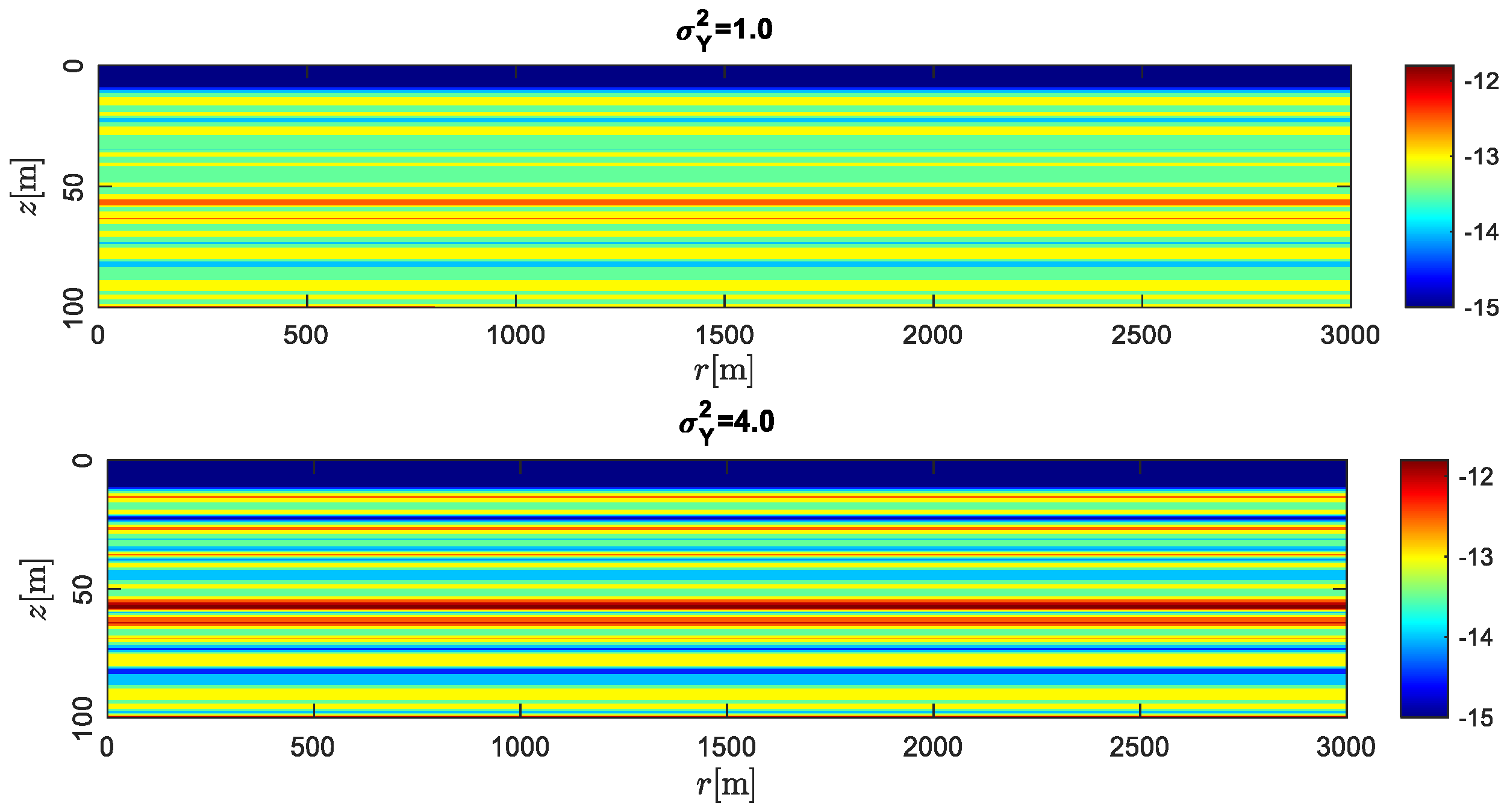
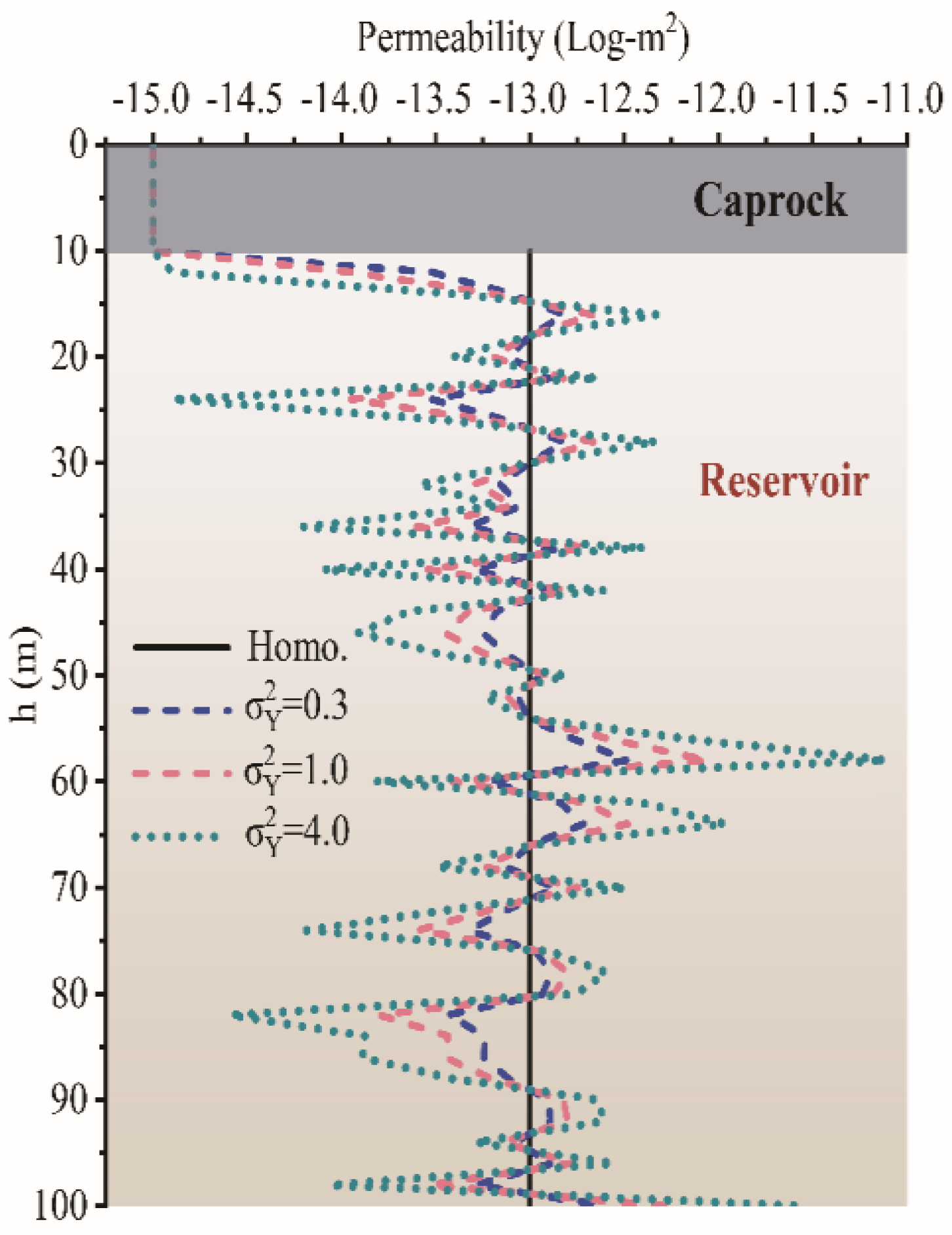
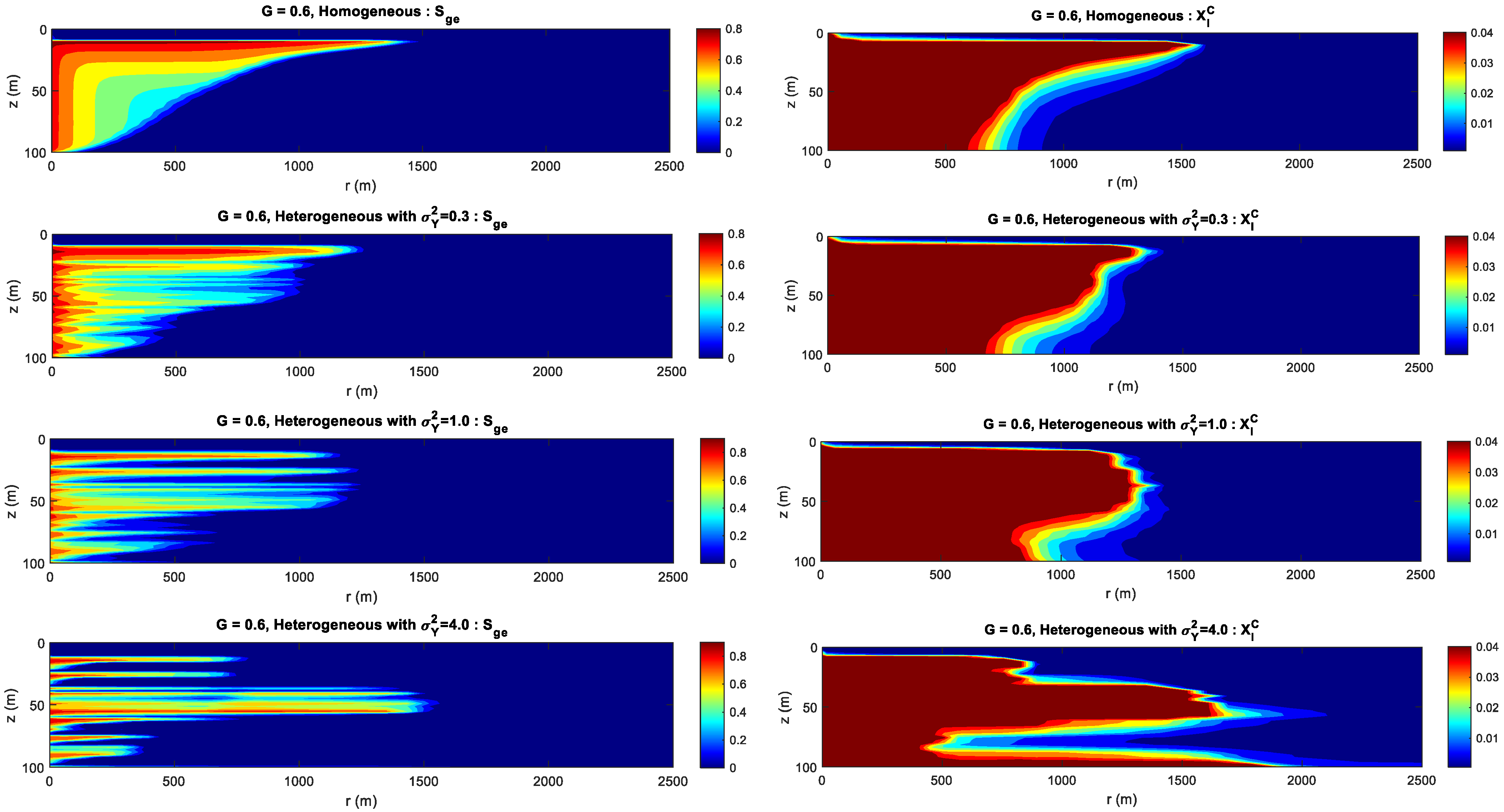
The permeability heterogeneity is the primary factor influencing the spatial mobility and distribution of CO2 injection. Heterogeneity variances σ Y 2 is considered to be an ideal representation of reservoir permeability.
(2)
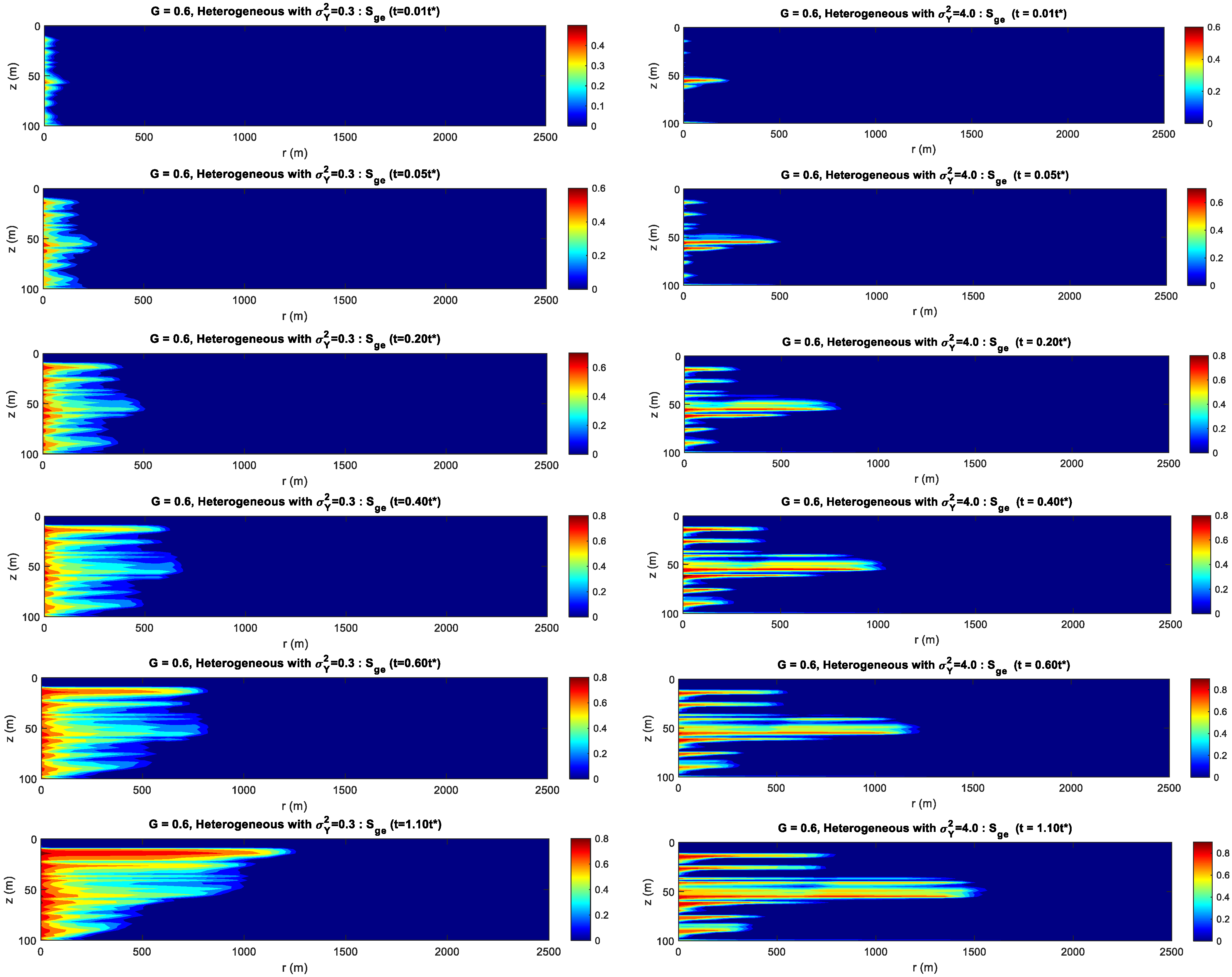
For the formation with the smaller heterogeneity, the upwind and lateral migration of the CO2 plume is relatively more uniform around the injection well. For the bigger heterogeneity, CO2 preferentially migrates along the horizontal layer without accompanying the vertical migration.
(3)
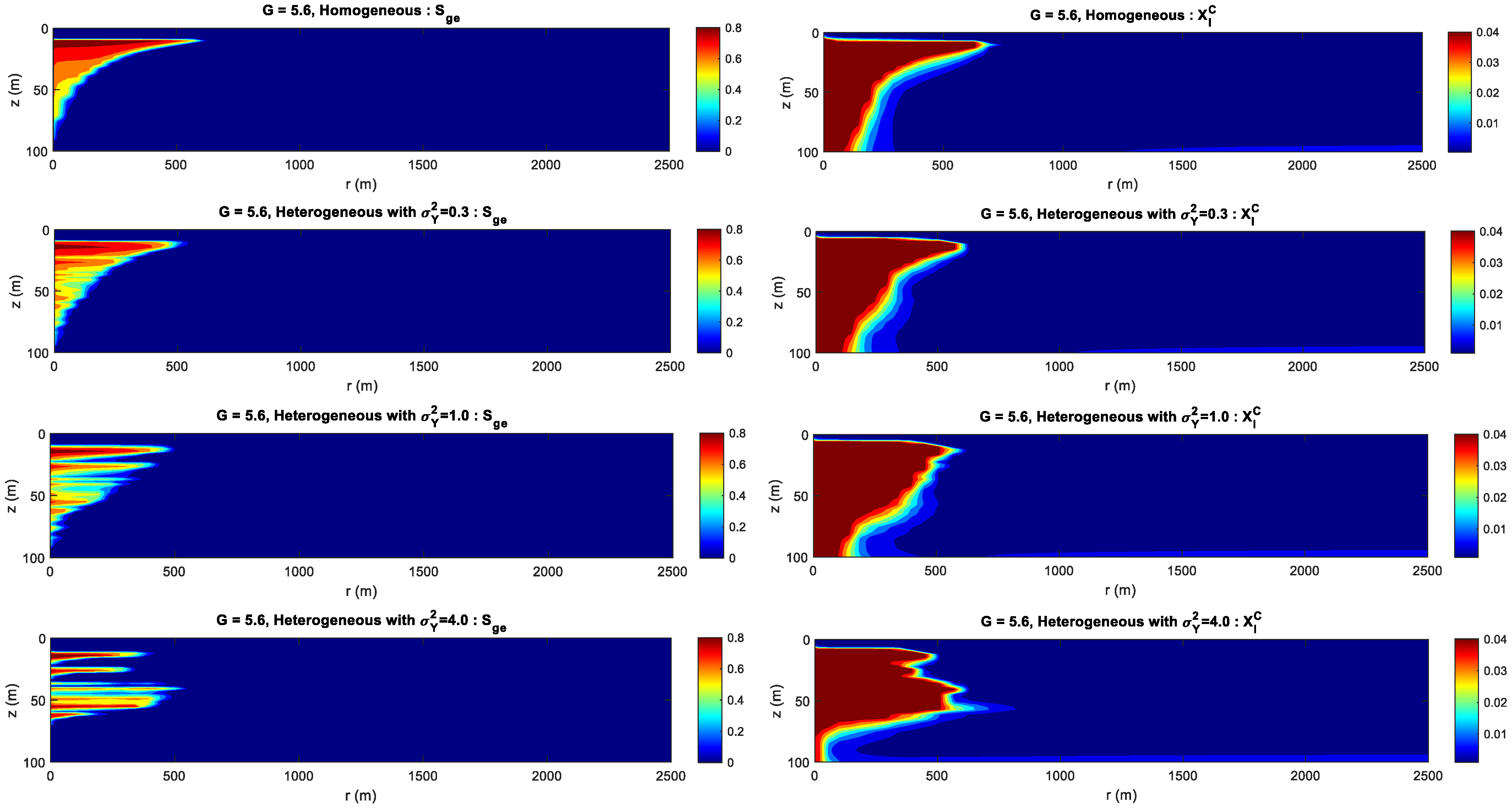
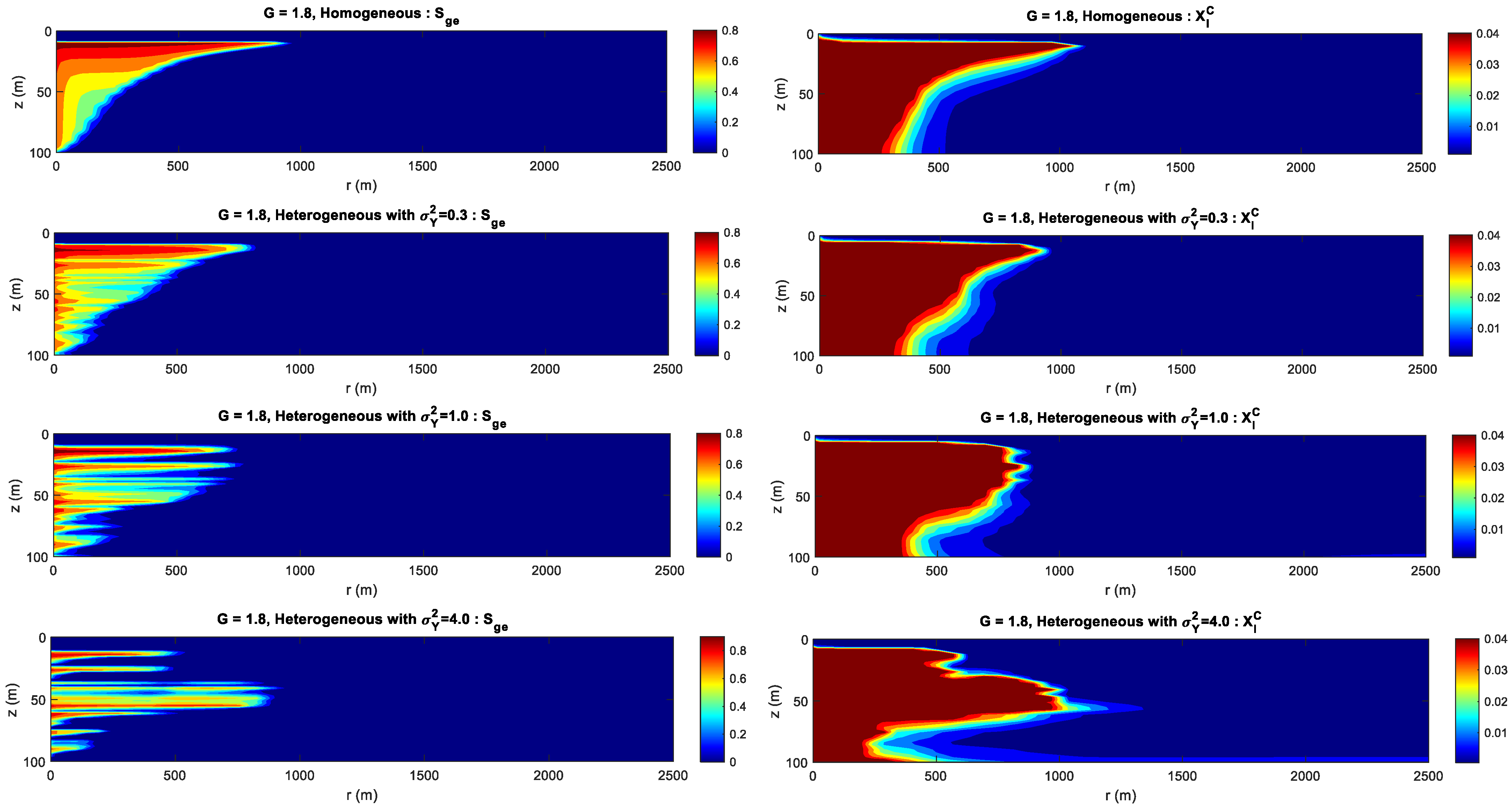
For the formation with the bigger gravity index, gravity index is the dominant factor controlling CO2 migration. For the medium gravity index, the upward and lateral migration of the CO2 plume is determined by the gravity index and heterogeneity. For the smaller gravity index, formation heterogeneity is the key factor influencing CO2 distribution.
(4)
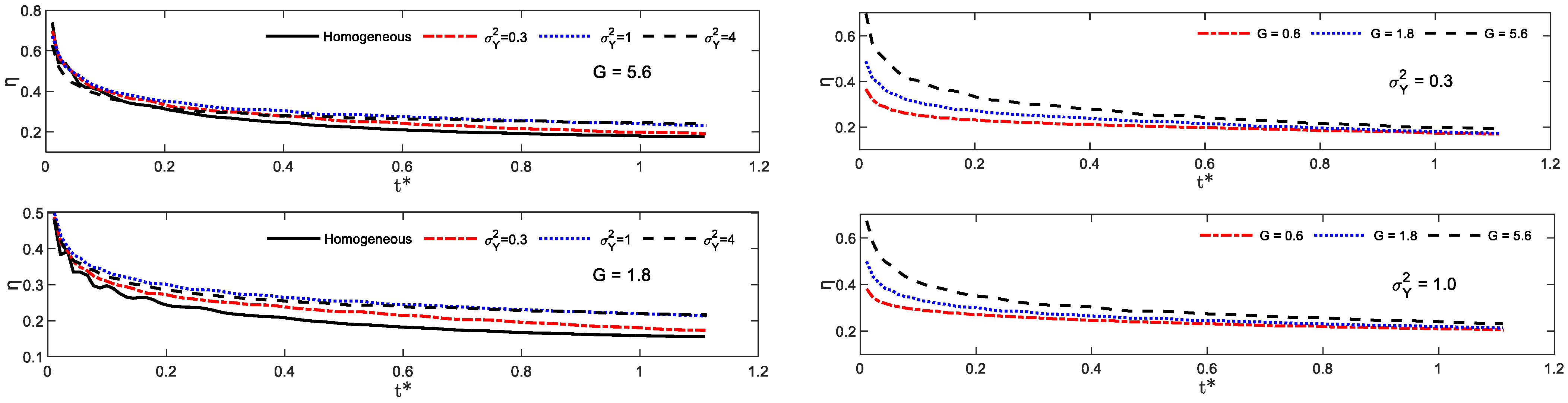
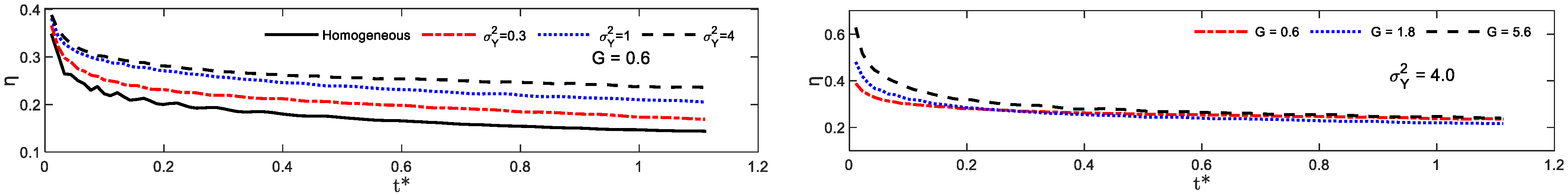
The dissolution curve shows a decreasing trend during CO2 injection. The dissolution curve with the higher gravity index is relatively higher at the initial injection period and the gap difference between dissolution curves approaches to a constant value. The permeability heterogeneity is the decisive factor in determining the finial CO2 dissolution efficiency.
(5)
From a practical point of view, most GCS field sites operate under G σ Y 2 . It is suggested to store CO2 in formations with relatively larger heterogeneity coefficient σ Y 2 .
(6)
Reactive 3-Phase flow model for geological sequestration is considered for future research. It will be a more sophisticated analysis of the GCS, incorporating the chemical reaction among aqueous species and rock-forming minerals, as well as the partition between gaseous CO2 phase and liquid brine phase.

Author Contributions

All of the authors contributed to publishing this paper. Y.L. and X.F. contributed to the research goals and aims; J.G., C.Y. and X.Z. contributed to the writing; W.L. and H.L. contributed to the language and pictures. All authors have read and agreed to the published version of the manuscript.

Funding

This work was financially supported by National Natural Science Foundation of China (No. 52274231 and No. 52034006), ZhanJiang Science and Technology Project (No. 2022A01061), and ZhanJiangWan Project (No. ZJW-2022-08-07).

Data Availability Statement

Data will be made available on request.

Acknowledgments

Special thanks to Y.F. Wang, who is a scientist at IFPEN (Rueil-Malmaison, France) and the developer of the two-flow code.

Conflicts of Interest

The authors declare that they have no known competing financial interests or personal relationships that could have appeared to influence the work reported in this paper.

References

  1. IPCC. Climate change 2007: Mitigation of climate change: Contribution of working group III to the fourth assessment report of the intergovernmental panel on climate change. Choice Rev. Online 2008. [Google Scholar] [CrossRef]
  2. Haszeldine, R.S.; Flude, S.; Johnson, G.; Scott, V. Negative emissions technologies and carbon capture and storage to achieve the Paris agreement commitments. Phil. Trans. R. Soc. A 2018, 376, 20160447. [Google Scholar] [CrossRef] [PubMed] [Green Version]
  3. Song, H.; Huang, G.; Li, T.; Zhang, Y.; Lou, Y. Analytical model of CO2 storage efficiency in saline aquifer with vertical heterogeneity. J. Nat. Gas Sci. Eng. 2014, 18, 77–89. [Google Scholar] [CrossRef]
  4. Vilarrasa, V.; Bolster, D.; Olivella, S.; Carrera, J. Coupled hydromechanical modeling of CO2 sequestration in deep saline aquifers. Int. J. Greenh. Gas Control 2010, 4, 910–919. [Google Scholar] [CrossRef] [Green Version]
  5. Riaz, A.; Hesse, M.; Tchelepi, H.A.; Orr, F.M. Onset of convection in a gravitationally unstable diffusive boundary layer in porous media. J. Fluid Mech. 2006, 548, 87–111. [Google Scholar] [CrossRef]
  6. Fang, Y.; Baojun, B.; Dazhen, T.; Dunn-Norman, S.; Wronkiewicz, D. Characteristics of CO2 sequestration in saline aquifers. Petrol. Sci. 2010, 7, 83–92. [Google Scholar]
  7. Kearns, J.; Teletzke, G.; Palmer, J.; Thomann, H.; Kheshgi, H.; Chen, Y.H.H.; Herzog, H. Developing a consistent database for regional geologic CO2 storage capacity worldwide. Energy Procedia 2017, 114, 4697–4709. [Google Scholar] [CrossRef]
  8. Zapata, Y.; Kristensen, M.R.; Huerta, N.; Brown, C.; Kabir, C.S.; Reza, Z. CO2 geological storage: Critical insights on plume dynamics and storage efficiency during long-term injection and post-injection periods. J. Nat. Gas Sci. Eng. 2020, 83, 103. [Google Scholar] [CrossRef]
  9. Singh, A.K.; Boettcher, N.; Wang, W.; Park, C.H.; Goerke, U.J.; Kolditz, O. Nonisothermal effects on two-phase flow in porous medium: CO2 disposal into a saline aquifer. Energy Proc. 2011, 4, 3889–3895. [Google Scholar] [CrossRef] [Green Version]
  10. Benson, S.M.; Cole, D.R. CO2 sequestration in deep sedimentary formations. Elements 2008, 4, 325–331. [Google Scholar] [CrossRef]
  11. Agartan, E.; Trevisan, L.; Cihan, A.; Birkholzer, J.; Zhou, Q.; Tissa, H. Illangasekare. Experimental study on effects of geologic heterogeneity in enhancing dissolution trapping of supercritical CO2. Water Resour. Res. 2015, 51, 1635–1648. [Google Scholar] [CrossRef]
  12. Kumar, S.; Foroozesh, J.; Edlmann, K.; Rezk, M.G.; Lim, C.Y. A comprehensive review of value-added CO2 sequestration in subsurface saline aquifers (Review). J. Nat. Gas Sci. Eng. 2020, 81, 103437. [Google Scholar] [CrossRef]
  13. Zhang, D.; Song, J. Mechanisms for Geological Carbon Sequestration. Procedia IUTAM 2014, 10, 319–327. [Google Scholar] [CrossRef] [Green Version]
  14. Saadatpoor, E.; Bryant, S.L.; Sepehrnoori, K. New trapping mechanism in carbon sequestration. Transp. Porous Media 2010, 82, 3–17. [Google Scholar] [CrossRef]
  15. Burnside, N.M.; Naylor, M. Review and implications of relative permeability of CO2/brine systems and residual trapping of CO2. Int. J. Greenh. Gas Control 2014, 23, 1–11. [Google Scholar] [CrossRef] [Green Version]
  16. Gershenzon, N.I.; Ritzi, R.W.; Dominic, D.F.; Mehnert, E.; Okwen, R.T. Comparison of CO2 trapping in highly heterogeneous reservoirs with Brooks-Corey and van Genuchten type capillary pressure curves. Adv. Water Resour. 2016, 96, 225–236. [Google Scholar] [CrossRef] [Green Version]
  17. Gershenzon, N.I.; Ritzi, R.W.; Dominic, D.F.; Mehnert, E.; Okwen, R.T. Capillary trapping of CO2 in heterogeneous reservoirs during the injection period. Int. J. Greenh. Gas Control 2017, 59, 13–23. [Google Scholar] [CrossRef] [Green Version]
  18. Adebayo, A.R. Sequential storage and in-situ tracking of gas in geological formations by a systematic and cyclic foam injection-A useful application for mitigating leakage risk during gas injection. J. Nat. Gas Sci. Eng. 2019, 62, 1–12. [Google Scholar] [CrossRef]
  19. Xu, T.; Apps, J.A.; Pruess, K. Numerical simulation of CO2 disposal by mineral trapping in deep aquifers. Appl. Geochem. 2004, 19, 917–936. [Google Scholar] [CrossRef]
  20. Xu, T.; Apps, J.A.; Pruess, K. Mineral sequestration of carbon dioxide in a sandstone-shale system. Chem. Geol. 2005, 217, 295–318. [Google Scholar] [CrossRef]
  21. Gaus, I.; Audigane, P.; Andre, L.; Lions, J.; Jacquemet, N.; Durst, P.; Azaroual, M. Geochemical and solute transport modelling for CO2 storage, what to expect from it? Int. J. Greenh. Gas Control 2008, 2, 605–625. [Google Scholar] [CrossRef] [Green Version]
  22. De Silva, G.P.D.; Ranjith, P.G.; Perera, M.S.A. Geochemical aspects of CO2 sequestration in deep saline aquifers: A review. Fuel 2015, 155, 128–143. [Google Scholar] [CrossRef]
  23. Gilmore, K.A.; Neufeld, J.A.; Bickle, M.J. CO2 Dissolution Trapping Rates in Heterogeneous Porous Media. Geophys. Res. Lett. 2020, 47, e2020GL087001. [Google Scholar] [CrossRef]
  24. Sathaye, K.J.; Hesse, M.A.; Cassidy, M.; Stockli, D.F. Constraints on the magnitude and rate of CO2 dissolution at Bravo Dome natural gas field. Proc. Natl. Acad. Sci. USA 2014, 111, 15332–15337. [Google Scholar] [CrossRef] [PubMed]
  25. Kim, K.Y.; Kim, M.; Oh, J. Core-scale investigation of the effect of heterogeneity on the dynamics of residual and dissolution trapping of carbon dioxide. J. Hydrol. 2021, 596, 126109. [Google Scholar] [CrossRef]
  26. Sohal, M.A.; Le Gallo, Y.; Audigane, P.; de Dios, J.C.; Rigby, S.P. Effect of geological heterogeneities on reservoir storage capacity and migration of CO2 plume in a deep saline fractured carbonate aquifer. Int. J. Greenh. Gas Control 2021, 108, 103306. [Google Scholar] [CrossRef]
  27. Singh, M.; Chaudhuri, A.; Soltanian, M.R.; Stauffer, P.H. Coupled multiphase flow and transport simulation to model CO2 dissolution and local capillary trapping in permeability and capillary heterogeneous reservoir. Int. J. Greenh. Gas Control 2021, 108, 103329. [Google Scholar] [CrossRef]
  28. Onoja, M.U.; Williams, J.D.; Vosper, H.; Shariatipour, S.M. Effect of sedimentary heterogeneities in the sealing formation on predictive analysis of geological CO2 storage. Int. J. Greenh. Gas Control 2019, 82, 229–243. [Google Scholar] [CrossRef] [Green Version]
  29. Mouche, E.; Hayek, M.; Mugler, C. Upscaling of CO2 vertical migration through a periodic layered porous medium: The capillary-free and capillary-dominant cases. Adv. Water Resour. 2010, 33, 1164–1175. [Google Scholar] [CrossRef]
  30. Green, C.; Ennis-King, J.; Pruess, K. Effect of Vertical Heterogeneity on Long-Term Migration of CO2 in Saline Formations. Energy Procedia 2009, 1, 1823–1830. [Google Scholar] [CrossRef] [Green Version]
  31. Deng, H.L.; Stauffer, P.H.; Dai, Z.X.; Jiao, Z.S.; Surdam, R.C. Simulation of industrial-scale CO2 storage: Multi-scale heterogeneity and its impacts on storage capacity, injectivity and leakage. Int. J. Greenh. Gas Control 2012, 10, 397–418. [Google Scholar] [CrossRef]
  32. Kim, M.; Kim, K.-Y.; Han, W.S.; Oh, J.; Park, E. Density-driven convection in a fractured porous media: Implications for geological CO2 storage. Water Resour. Res. 2019, 55, 5852–5870. [Google Scholar] [CrossRef]
  33. Shafabakhsh, P.; Ataie-Ashtiani, B.; Simmons, C.T.; Younes, A.; Fahs, M. Convective-Reactive Transport of Dissolved CO2 in Fractured-Geological Formations. Int. J. Greenh. Gas Control 2021, 109, 103365. [Google Scholar] [CrossRef]
  34. Galkin, S.V.; Martyushev, D.A.; Osovetsky, B.M.; Kazymov, K.P.; Song, H. Evaluation of void space of complicated potentially oil-bearing carbonate formation using X-ray tomography and electron microscopy methods. Energy Rep. 2022, 8, 6245–6257. [Google Scholar] [CrossRef]
  35. Martyushev, D.A.; Ponomareva, I.N.; Chukhlov, A.S.; Davoodi, S.; Osovetsky, B.M.; Kazymov, K.P.; Yang, Y. Study of void space structure and its influence on carbonate reservoir properties: X-ray microtomography, electron microscopy, and well testing. Mar. Pet. Geol. 2023, 151, 106192. [Google Scholar] [CrossRef]
  36. Martyushev, D.A.; Govindarajan, S.K.; Li, Y.; Yang, Y. Experimental study of the influence of the content of calcite and dolomite in the rock on the efficiency of acid treatment. J. Pet. Sci. Eng. 2022, 208, 109770. [Google Scholar] [CrossRef]
  37. Martyushev, D.A. Improving the geological and hydrodynamic model a carbonate oil object by taking into account the permeability anisotropy parameter. J. Min. Inst. 2020, 243, 313–318. [Google Scholar] [CrossRef]
  38. Martyushev, D.A.; Ponomareva, I.N.; Osovetsky, B.M.; Kazymov, K.P.; Tomilina, E.M.; Lebedeva, A.S.; Chukhlov, A.S. Study of the structure and development of oil deposits in carbonate reservoirs using field data and X-ray microtomography. Georesursy 2022, 24, 114–124. [Google Scholar]
  39. Oh, J.; Kim, K.Y.; Han, W.S.; Park, E.; Kim, J.C. Migration behavior of supercritical and liquid CO2 in a stratified system: Experiments and numerical simulations. Water Resour. Res. 2015, 51, 7937–7958. [Google Scholar] [CrossRef]
  40. Rasmusson, K.; Tsang, C.-F.; Tsang, Y.; Rasmusson, M.; Pan, L.; Fagerlund, F.; Bensabat, J.; Niemi, A. Distribution of injected CO2 in a stratified saline reservoir accounting for coupled wellbore-reservoir flow. Greenh. Gases Sci. Technol. 2015, 5, 419–436. [Google Scholar] [CrossRef]
  41. Lie, K.-A. An Introduction to Reservoir Simulation Using MATLAB/GNU Octave: User Guide for the MATLAB Reservoir Simulation Toolbox (MRST); Cambridge University Press: Cambridge, UK, 2019. [Google Scholar]
  42. Spycher, N.; Pruess, K. CO2-H2O mixtures in the geological sequestration of CO2. II. Partitioning in chloride brines at 12-100 °C and up to 600 bar. Geochim. Cosmochim. Acta 2005, 69, 3309–3320. [Google Scholar] [CrossRef]
  43. Spycher, N.; Pruess, K.; Ennis-King, J. CO2-H2O mixtures in the geological sequestration of CO2. I. Assessment and calculation of mutual solubilities from 12 to 100 °C and up to 600 bar. Geochim. Cosmochim. Acta 2003, 67, 3015–3031. [Google Scholar] [CrossRef]
  44. Wang, Y.; Fernàndez-Garcia, D.; Saaltink, M.W. Carbon Dioxide (CO2) Dissolution Efficiency During Geological Carbon Sequestration (GCS) in Randomly Stratified Formations. Water Resour. Res. 2022, 58, e2022WR032325. [Google Scholar] [CrossRef]
  45. Leverett, M.C. Capillary behavior in porous solids. Trans. AIME 1941, 142, 159–172. [Google Scholar] [CrossRef]
  46. Buckley, S.E.; Leverett, M.C. Mechanism of fluid displacement in sands. Trans. AIME 1942, 146, 107–116. [Google Scholar] [CrossRef]
  47. Juanes, R.; Spiteri, E.J.; Orr, F.M.; Blunt, M.J. Impact of relative permeability hysteresis on geological CO2 storage. Water Resour. Res. 2006, 42, W12418. [Google Scholar] [CrossRef]
  48. Krevor, S.C.; Pini, R.; Zuo, L.; Benson, S.M. Relative permeability and trapping of CO2 and water in sandstone rocks at reservoir conditions. Water Resour. Res. 2012, 48, W02532. [Google Scholar] [CrossRef]
  49. McWhorter, D.B.; Sunada, D.K. Exact integral solutions for two-phase flow. Water Resour. Res. 1990, 26, 399–413. [Google Scholar] [CrossRef]
  50. Nordbotten, J.M.; Celia, M.A. Similarity solutions for fluid injection into confined aquifers. J. Fluid Mech. 2006, 51, 307–327. [Google Scholar] [CrossRef]
  51. Bai, T.; Tahmasebi, P. Sequential Gaussian simulation for geosystems modeling: A machine learning approach. Geosci. Front. 2022, 13, 101258. [Google Scholar] [CrossRef]
Figure 1. Saturation distribution of the gas phase (the red dotted line is the sharp interface calculated by Equation (25) using our method).
Energies 16 05219 g001
Figure 2. Comparison of the numeral result with the solution by Nordbotten [50].
Energies 16 05219 g002
Figure 3. Sketch of the simulation setup (different colors display geological heterogeneities).
Energies 16 05219 g003
Figure 4. Logarithm permeability distributions of the stratified reservoir with different variances.
Energies 16 05219 g004aEnergies 16 05219 g004b
Figure 5. Logarithm permeability distributions along the reservoir depth.
Energies 16 05219 g005
Figure 6. Spatial mobility and distribution of CO2 for Case 10 and Case 12 over time during CO2 injection.
Energies 16 05219 g006
Figure 7. Distribution of the effective saturation ( S g e ) and mass fraction of aqueous CO2 in brine ( X l C ) when t = 1.1 t .
Energies 16 05219 g007
Figure 8. Distribution of the effective saturation ( S g e ) and mass fraction of aqueous CO2 in brine ( X l C ) when t = 1.1 t .
Energies 16 05219 g008
Figure 9. Distribution of the effective saturation ( S g e ) and mass fraction of aqueous CO2 in brine ( X l C ) when t = 1.1 t .
Energies 16 05219 g009
Figure 10. Temporal evolution of CO2 dissolution efficiency in brine.
Energies 16 05219 g010aEnergies 16 05219 g010b
Table 1. Values of the main parameters for relative permeability.
ParameterValueParameterValue
k r l m 1.0 k r g m 1.0
α p 5.0 m p 0.4
ϵ p 0.5 γ p 0.5
Table 2. Summary of the parameters adopted for GCS.
ParametersSymbolUnitsValues
Domain size(R, b)[m](3000, 100)
Grid discretization(Nr, Nz)[–](100, 100)
Porosityϕ[–]0.1
Mean permeability k g [m2]10−13
Initial liquid pressurepl[bar]150
Initial gas pressurepg[bar]1
Well radiusrw[m]0.1
Total injection massMinj[Mt]2.5
Residual saturations(SlrSgr)[–](0.2, 0)
Hydrodynamic dispersivities(αLαT)[m](5, 1)
Molecular diffusion coefficientDm[m2⋅s−1]10−9
Salinity m l S [molal]0.1
TemperatureTc[°C]60
Simulation time t[s]3.15 × 10⁷
Table 3. Gravity index calculations in different simulated cases.
Case Q ( M t / y ) k g ( m 2 ) σ Y 2 G
17.510−1300.6
22.510−1301.8
30.810−1305.6
40.810−130.35.6
50.810−131.05.6
60.810−134.05.6
72.510−130.31.8
82.510−131.01.8
92.510−134.01.8
107.510−130.30.6
117.510−131.00.6
127.510−134.00.6
Disclaimer/Publisher’s Note: The statements, opinions and data contained in all publications are solely those of the individual author(s) and contributor(s) and not of MDPI and/or the editor(s). MDPI and/or the editor(s) disclaim responsibility for any injury to people or property resulting from any ideas, methods, instructions or products referred to in the content.

