Article

A Three-Phase Phase-Modular Single-Ended Primary-Inductance Converter Rectifier Operating in Discontinuous Conduction Mode for Small-Scale Wind Turbine Applications

by
Guilherme Ferreira de Lima
1,†,
William de Jesus Kremes
1,†,
Hugo Valadares Siqueira
1,†,
Bahar Aliakbarian
2,*,†,
Attilio Converti
3,† and
Carlos Henrique Illa Font
1,†
1
Graduate Program in Electrical Engineering, Federal University of Technology-Paraná—UTFPR, Ponta Grossa 84017-220, PR, Brazil
2
Department of Biosystems and Agricultural Engineering, The Axia Institute, Michigan State University, 1910 West St. Andrews Rd, Midland, MI 48640, USA
3
Department of Civil, Chemical and Environmental Engineering, University of Genoa, Via Opera Pia, 15, 16145 Genoa, Italy
*
Author to whom correspondence should be addressed.
These authors contributed equally to this work.
Energies 2023, 16(13), 5220; https://doi.org/10.3390/en16135220
Submission received: 31 May 2023 / Revised: 30 June 2023 / Accepted: 4 July 2023 / Published: 7 July 2023
(This article belongs to the Special Issue Green Technologies for Energy Transition)

Abstract

:
Small-scale wind turbines play an important role in distributed generation since customers can use their houses, farms, and business to produce electric energy. The development of the power electronics system that processes the electric energy from small-scale wind turbines is a concern due to cost, simplicity, efficiency, and performance trade-offs. This paper presents the results of applying a three-phase phase-modular single-ended primary-inductance converter rectifier to processing the energy of a small-scale wind turbine system. The rectifier was designed according to the specifications of a commercial small-scale wind turbine system and tested in an emulator workbench, providing experimental data on the operation of the rectifier in this application. The rectifier can process the energy of a non-sinusoidal three-phase system since the permanent magnet synchronous generator has trapezoidal waveforms. The results show that the rectifier has the advantages of (i) using the inductance of the generator as the input filter inductor of the rectifier, (ii) providing input currents with the same shape as the voltages and in phase without the use of a current control system, (iii) simplicity of control of the DC output voltage and PWM modulation, and (iv) phase-modular characteristics that allow operating with phase fault without any additional control techniques. Due to the operation in discontinuous conduction mode, low efficiency in high power and/or low input voltage specifications are disadvantages.

1. Introduction

Renewable energy sources are a sustainable solution for increasing electric energy generation worldwide. The field of 100% renewable energy (RE) systems research proposes that this can be achieved entirely using renewable sources, not only for the electricity sector but for all energy and non-energy industries [1].
Wind energy has become an essential part of human life worldwide and has undergone substantial development in different areas in recent decades [2]. Onshore wind power in particular plays a pivotal role in modern power systems due to its low costs [3]. In small-scale generation, customers can use their houses, farms, and business to produce electric energy, reducing tariffs and contributing to integrated grids and the environment [4,5,6].
Most studies and commercially available small wind turbines (SWTs) are based on permanent magnet synchronous generators (PMSG) [7,8,9]. Small-scale wind turbines operate with variable speed, and the grid connection is made through static power converters with system control to maximize the power generated and decrease harmonics on the grid while using simple, low-cost, and robust solutions [10,11,12,13,14,15,16,17,18,19,20,21,22].
The energy electronic processing from wind turbines is generally carried out using a two-stage approach: the first stage is realized by an AC–DC converter (rectifier) and the second stage is performed by a DC–AC converter (inverter) [23].
Regarding the rectifier stage, two types are widely employed: diode bridge rectifiers and pulse width modulated (PWM) rectifiers. Diode bridge rectifiers are low-cost, simple, and robust solutions. However, they present a low power factor because they drain currents with high harmonic content [24]. Specifically, in the application of rectifiers for processing the energy of small-scale wind turbines, the harmonic components of the current will produce parasitic torques in the generator. Therefore, the losses and the temperature in the generator will increase, decreasing the overall efficiency.
PWM rectifiers allow sinusoidal currents in wind turbines and maximum power tracking for different wind speeds. A classic solution in this conversion system is with boost rectifier topologies that need an output voltage higher than the input voltage for proper operation [24,25]. However, generator voltage depends on wind speed, which can be a limiter [26]. Moreover, a current control system must be implemented in each rectifier phase to achieve a high power factor, increasing the cost and complexity through voltage and current sensors.
The utilization of topologies based on single-ended primary-inductance converter (SEPIC) rectifiers allows operation as a step down/up rectifier. Moreover, when operating in discontinuous conduction mode (DCM), SEPIC rectifiers can naturally provide a high power factor without a current control system [27]. This characteristic can maximize the power extracted by the SWT, mainly in low-wind speed operation [28].
This paper proposes a three-phase phase-modular SEPIC rectifier operating in DCM for processing energy in small-scale wind turbine applications. This rectifier was first presented in ref. [28], in which the rectifier was tested with an AC power source at input, and the high power factor corrector capability was verified. The contributions of this paper with regard to previous studies are as follows:
  • Theoretical analysis to obtain the dynamic model for output voltage control;
  • Experimental analysis of the rectifier processing the energy from a small-scale wind turbine emulator workbench;
  • Efficiency analysis.
First, the rectifier topology and theoretical analysis are presented in Section 2, with the discussion of two modulation strategies. Section 3 presents the main design equations for the power stage and losses calculation. Section 4 presents the control and dynamic model for controlling the DC output voltage. The prototype assembly and the experimental results are presented in Section 5. Finally, the conclusions are stated in Section 6.

2. Theoretical Analysis

The phase-modular SEPIC rectifier with two switches per module is presented in Figure 1. The rectifier is connected to a six-wire three-phase grid obtained through a PMSG with open-end stator windings. In this application, the SEPIC rectifier input inductances ( L i A ,   L i B   and   L i C ) can be eliminated, and stator inductances can be used as rectifier input inductances.
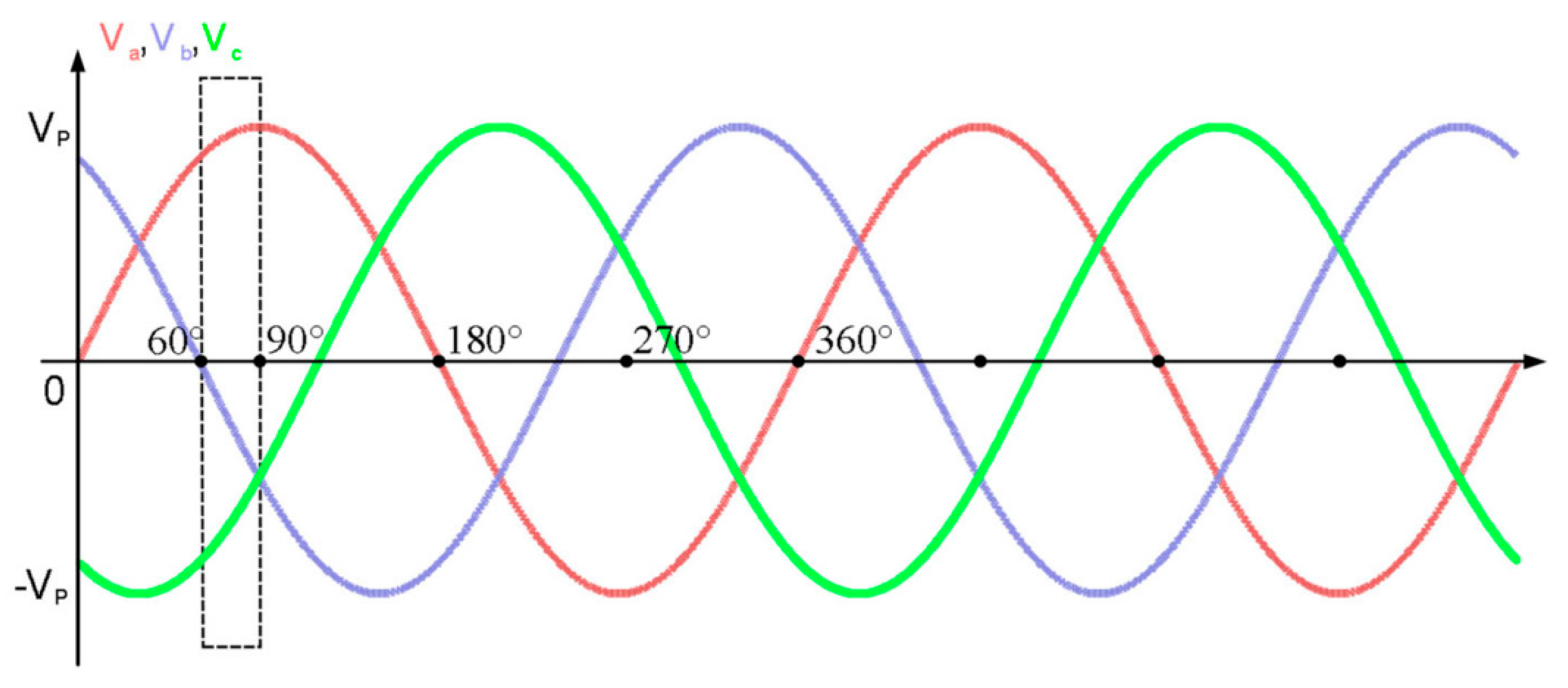
When operating in DCM, this rectifier has input currents naturally in phase with the input voltages in a way that does not require the use of a current control system [29,30] to achieve a high power factor. As a result of modular characteristics, the three-phase rectifier can be analyzed and designed as three independent modules (single-phase), each responsible for a third of the output power. To perform theoretical analysis, we considered the input voltage interval of 60 < ω t < 90 , as depicted in Figure 2. Consequently, the input voltages satisfy the inequality shown in Equation (1):
| V A | > | V B | > | V C |

2.1. PWM Techniques for the Three-Phase SEPIC Rectifier

Since the rectifier structure for each phase is realized with a bridgeless implementation, the modulation scheme can be performed in two different approaches. The three-phase rectifier modulated with conventional modulation presents the same command signal for both transistors, as represented in Figure 3.
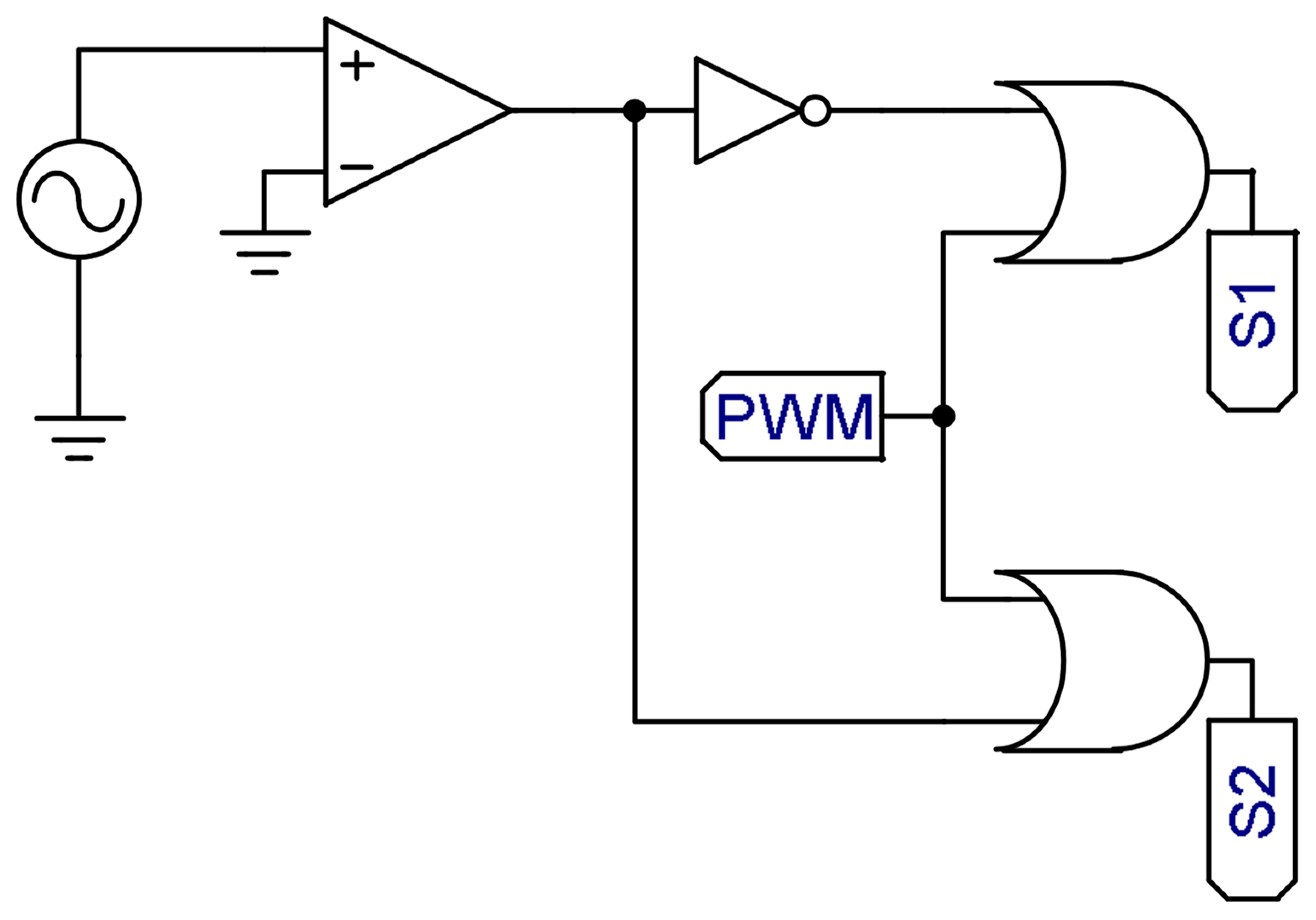
The alternative modulation proposed in [31] aims to reduce the losses by not conducting diodes in anti-parallel transistors. Figure 4 represents the command signals profile, where in the positive semi-cycle, the superior transistor is switched following the modulator comparison while the inferior transistor is turned on; the opposite occurs for the negative semi-cycle. Figure 5 shows a circuit for the implementation of alternative modulation. It is important to highlight that the alternative modulation must be synchronized with the input voltage of each phase. Therefore, it requires extra voltage sensors and the use of a phase-locked loop (PLL) circuit for synchronization.

2.2. Stages of Operation

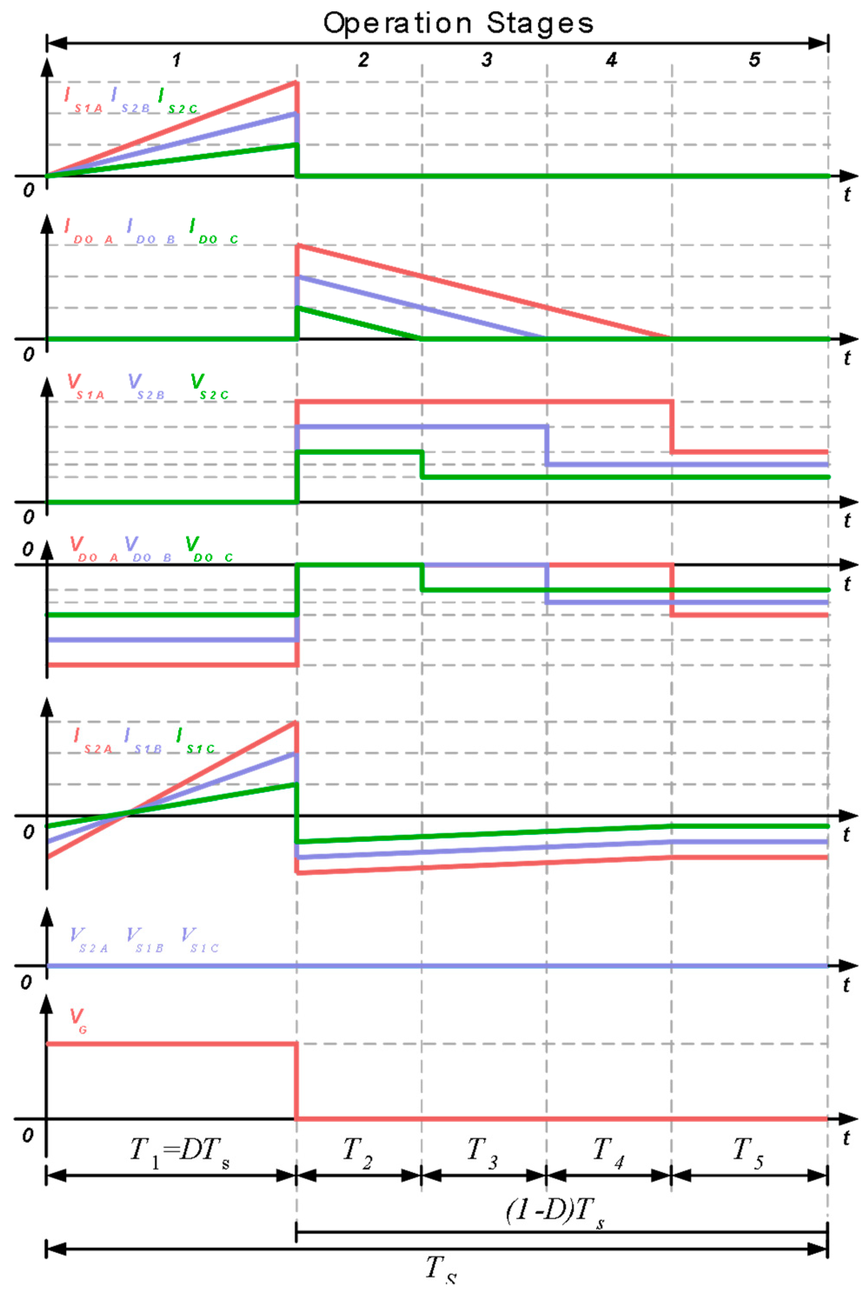
When operating with conventional PWM modulation, the SEPIC rectifier simultaneously presents the same command signal for all transistors. In DCM, the converter has five stages of operation, as seen in Figure 6.
During the first stage of operation, all transistors are turned on, and output diodes are blocked. The inductor currents increase according to the following relations: V A / L i A , V B / L i B , V C / L i C ,   V A / L o A , V B / L o B , V C / L o C . Meanwhile, the load is fed by capacitor C o .
The second stage of operation starts when all transistors are turned off. At this moment, the output diodes come into conduction, transferring the inductors’ storage energy to the load R o . At the input, current circulates through the anti-parallel diode according to the semi-cycle of input voltage at each moment. The inductor currents decrease according to the following relations: V o / L i A , V o / L i B , V o / L i C , V o / L o A , V o / L o B , V o / L o C .
When considering the input voltage interval 60 < ω t < 90 , the amplitude of each AC input voltage differs, and the storage energy on the passive elements of each module is also different. Therefore, the end of the energy transfer process of each module occurs at different times. Since the amplitude of AC voltage V C is smaller, the output diode of the third phase will be the first to stop conducting, as represented in the third stage of operation.
The fourth stage of operation starts when diode D o B blocks, and then the second module stops energy transfer to load R o and to capacitor C o . The fifth and last stage starts when diode D o A blocks, and the third module stops energy transfer to output. The capacitor C o feeds the load R o . The fifth stage indicates DCM since all semiconductors are blocked.

2.3. Ideal Waveforms

The ideal waveforms based on the operation stages section are illustrated in Figure 7, which shows the current and voltage waveforms on the transistors ( S 1 A ,   S 1 B ,   S 1 C ,   S 2 A , S 2 B ,   S 2 C ) , currents and voltages on the output diodes ( D o A , D o B , D o C ) , and the command signal for the transistors.

3. Design Equations and Losses Calculation

The main equations for the power circuit design are shown below [28]. Moreover, the losses calculation in each component is presented.

3.1. Inductor Design

Equations (2) and (3), respectively, are inductance values for the input and output inductors in each module. Output inductors are designed from values of input inductors, which, in turn, are calculated from a current ripple specification, ensuring the DCM operation.
L i = V p D Δ I L i f s
L o = L i R o V p 2 D 2 4 L i V o 2 f s R o V p 2 D 2
The root mean square (rms) input current value and the average and rms output current values on inductors are shown in Equations (4)–(6), respectively.
I L i r m s = 6 24 D 3 V p 2 [ 12 V o 2 L i D ( L i + 2 L o ) + L o 2 ( 16 V o 2 9 V p 2 D 2 ) ] V o 2 L i 2 L o 2 f s 2
I L o a v g = D 2 V p 2 ( L i + L o ) 4 V o L i L o f s
I L o r m s = 1 24 2 D 3 V p [ V p V o L i 2 ( 128 192 D ) + V p 2 L o D π ( 54 L i 27 L o ) + V o 2 L i 2 π ( 48 36 D ) ] π V o 2 L i 2 L o 2 f s 2

3.2. Capacitor Design

Equations (7) and (8) show input and output capacitance values, respectively. Input capacitors are designed from a voltage ripple specification, while the capacitor C o is designed from a specification of hold-up time (thold).
C i = D 2 V p [ D ( V p L o V o L i ) + 2 V o L i ] 2 8 V o 2 L i 2 L o Δ V C i f s 2
C o = 2 P o t h o l d V o 2 ( 0.9 V o ) 2

3.3. Semiconductor Design

The maximum voltage, maximum current, average current, and rms current values on transistors are given by Equations (9)–(12), respectively:
V S m a x = V p + V o
I S m a x = D V p ( L i + L o ) L i L o f s
I S a v g = D 2 V p [ 4 V o L i ( 4 D ) + L o ( V p D π + 8 V o ) ] 16 π V o L i L o f s
I S r m s = V p V o D 3 π 3 π V o [ L o 2 ( 16 9 D ) + 4 L i 2 ( 8 3 D ) + 32 L i L o ] + 2 V p ( 64 L o 2 + 96 L i L o ) 24 V o L i L o f s ,
while the maximum voltage across output diodes is given by Equation (13):
V D o m a x = V p + V o
The maximum, average, and rms current values on output diodes are shown in Equations (14)–(16), respectively.
I D o m a x = D V p ( L i + L o ) L i L o f s
I D o a v g = D 2 V p 2 ( L i + L o ) 4 V o L i L o f s
I D o r m s = 2 D V p ( L i + L o ) 3 L i L o f s D V p π V o
The maximum voltage and average current values for the rectifier diodes are shown in Equations (17) and (18), respectively.
V D r m a x = V p + V o
I D r a v g = D 2 V p ( L i + L o ) 2 π L i L o f s

3.4. Losses Calculation

The losses calculation approach in this paper considers the losses in transistors, diodes, and inductors. The transistor losses can be calculated using Equation (19), where RDSon is the conduction resistance, tf is the fall time, and tr is the rise time.
P S l o s s e s = R D S o n · I S r m s 2 + f s 2 · ( t f + t r ) · I S m a x · V S m a x
The diode losses can be calculated using Equation (20), where VF is the forward diode voltage for the output and rectifier diodes.
P D o , r l o s s e s = V F · I D o , r a v g
The losses in inductors are estimated from copper losses and magnetic core losses as presented in Equation (21), where lw is the wire length, ρc is the copper resistivity, Sw is the wire cross-sectional area, Bmax is the maximum flux density, Vn is the core volume, and a, b, and c are constants of magnetic material.
P L i , o l o s s e s = ρ c . l w S w · I L i , o r m s 2 + B m a x a · V n · ( b · f s + c · f s 2 )
The total losses in the rectifier can be estimated using Equation (22):
P l o s s e s = 6 · P S l o s s e s + 3 · P D o l o s s e s + 6 · P D r l o s s e s + 3 · P L i l o s s e s + 3 · P L o l o s s e s
Finally, the efficiency is estimated using Equation (23):
η = P o P o + P l o s s e s

4. Control and Dynamic Model

The control and modulation strategy are shown in Figure 8 through a block diagram. As the rectifier operates in DCM, it emulates a resistance for the input (e.g., for the PMSG). Consequently, the input currents have the exact shape of the respective input voltages without the necessity of a current control system. The control system is thus composed of a single voltage control system for controlling the DC output voltage.
The PWM modulator is implemented with a saw-tooth signal, performing a trailing edge modulation. Each transistor is commanded with the same command signal, implementing a simple command circuit.

4.1. Determination of Dynamic Model

To obtain the small-signal model for the control of the rectifier’s output voltage, the equivalent circuit shown in Figure 9 is considered [32]. The current i o ( t ) is composed of the sum of the output currents of each module, as shown in Equation (24):
i o ( t ) T s = i D o A ( t ) T s + i D o B ( t ) T s + i D o C ( t ) T s
The following differential equation, which describes the dynamic output voltage behavior, is obtained through the circuit analysis from the equivalent circuit depicted in Figure 9:
i o ( t ) T s = C o d v o ( t ) T s d t + v o ( t ) T s R o
For the linearization process, each variable in Equations (24) and (25) is rewritten as the sum of a constant value and a small-signal variable. The constant value represents the operation point (steady-state value), and the small-signal variable represents a perturbation around the operation point and is denoted by a  ^  mark on the variable. Therefore, it yields the following:
i o ( t ) T s = I o + i o ^ ( t ) v o ( t ) T s = V o + v o ^ ( t )
For the operation point, it yields Equation (27):
I o = C o d V o 2 d t + V o 2 R o I o = V o 2 R o
Replacing Equations (26) and (27) with Equation (25), we obtain Equation (28):
i o ^ ( t ) = C o d v o ^ ( t ) d t + v o ^ ( t ) R o
The average value of the output current can also be written in the form of Equation (29):
i o ( t ) T s = 3 d ( t ) 2 V p 2 ( L i + L o ) 4 v o ( t ) T s L i L o f s
It is observed in this expression that the current value i o ( t ) suffers variation when the duty cycle is changed. Therefore, any variation in the duty cycle also causes output voltage variation, causing a change in the current value. Consequently, applying a perturbation on duty cycle d(t) leads to a direct and indirect variation in the current i o ( t ) . The direct variation is generated by duty cycle alteration, while the indirect one is generated by output voltage variation. Thus, the current alteration for a specific duty cycle perturbation can be expressed as partial functions as shown in Equation (30):
i o ^ ( t ) = i o ( t ) T s d ( t ) d ^ ( t ) + i o ( t ) T s v o ( t ) T s v o ^ ( t )
Solving Equation (30), Equation (31) is obtained:
i o ^ ( t ) = 3 D V p 2 ( L i + L o ) 2 V o L i L o f s d ^ ( t ) 3 D 2 V p 2 ( L i + L o ) 4 V o 2 L i L o f s v o ^ ( t )
Equaling Equations (28) and (31) and applying the Laplace transform to the result of equality, the dynamic model represented by the transfer function for the small signal is obtained, as can be seen in Equation (32):
G ( s ) = v o ^ ( s ) d ^ ( s ) = 3 R o D V p 2 ( L i + L o ) 2 V o L i L o f s R o C o s + 3 R o D 2 V p 2 ( L i + L o ) 4 V o 2 L i L o f s + 1

4.2. Transfer Function Validation

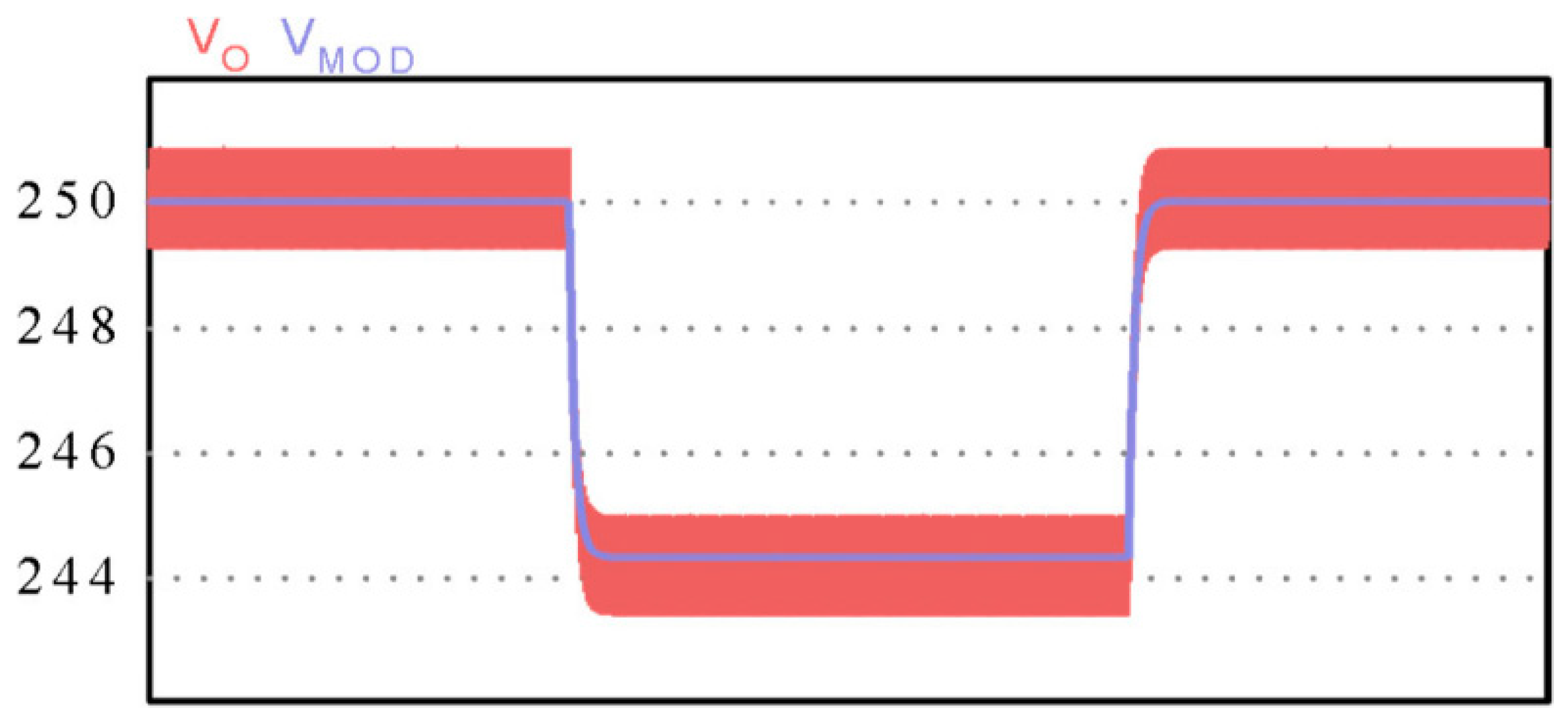
To validate the transfer function shown in Equation (32), a numeric simulation was performed using the values of the design specifications listed in Table 1 and the values of passive components listed in Table 2. The result obtained by applying negative and positive steps on the duty cycle of 2 % of its nominal value is shown in Figure 10, where it is compared with the circuit simulation result for the output voltage. Such a comparison highlights the similarity between the simulated rectifier dynamic response and the small-signal dynamic model response. Therefore, it is possible to use this model to represent the dynamic behavior of the output voltage of the rectifier.

5. Prototype and Experimental Results

In order to demonstrate the experimental operation of the SEPIC rectifier, a proof-of-concept prototype was built with 1500 W of rated power. The other design specifications are shown in Table 1. A photograph of the prototype is presented in Figure 11, and the bill of components is presented in Table 2.
The experimental results were obtained from a small-scale wind turbine emulator workbench built with a frequency converter, a permanent magnet synchronous motor as a primary machine, a gear box, a torque sensor, and a permanent magnet synchronous generator. A picture of the workbench can be seen in Figure 12.
The workbench can operate with maximum values of 3 kW of rated power, 12 m/s of rated wind speed, and 350 rpm of rated angular speed. The permanent magnet synchronous generator has 3 kW of rated power, 90 V of rated voltage, 30 Hz of rated frequency, ten poles, and a trapezoidal-shaped back-EMF (electromotive force).
The experimental verification on the small-scale wind turbine workbench emulates the operating conditions of the rectifier in a wind turbine, which is crucial to verify its performance and validate the theoretical studies.
The current waveforms drained from the PMSG are shown in Figure 13. It is possible to observe waveforms with a trapezoidal shape, and the currents present rms values of 5.23, 5.17, and 4.78 A.
The voltage (green) and current (yellow) waveforms in phase A are shown in Figure 14, with the rms voltage value in phase A approximately 90 V and frequency 30 Hz. From the trends outlined in this figure, it is possible to conclude that the rectifier provides a high power factor since the voltage and the current have the same shape, and there is no phase shift between voltage and current. Additionally, the rectifier can operate with non-sinusoidal waveforms.
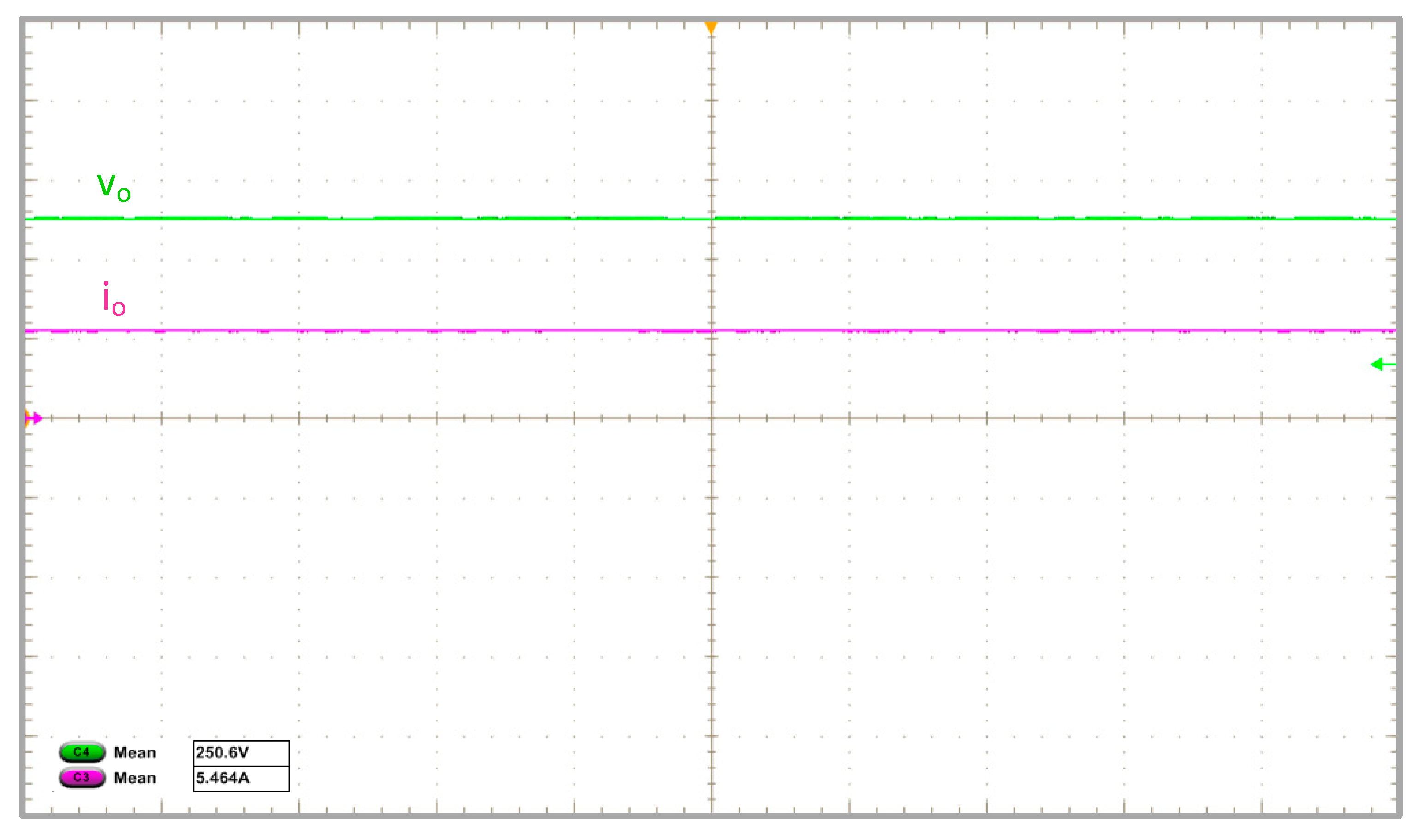
On the other hand, the output voltage and current waveforms are shown in Figure 15. The average output voltage is approximately 250 V, while the average output current is 5.5 A. Therefore, the output power is about 1.375 kW.
From Figure 15, it is possible to observe that the output voltage is kept at approximately 250 V by the action of the voltage controller.
The experimental and theoretical efficiency curves as a function of the output power are depicted in Figure 16. The rectifier presents an efficiency greater than 90% for a wide power variation. The maximum efficiency is about 91.5% when the rectifier processes about half of the rated power.
Figure 17 exhibits the theoretical losses distribution at rated power per component. It should be highlighted that the largest proportion of losses is in the transistors (47.4%) and the output inductors (21.4%).
The experimental results show the proposal’s feasibility when processing the energy of a small-scale wind turbine system. The three-phase phase-modular SEPIC rectifier provides high energy quality, maximizing the active power extracted from the wind turbine.

6. Conclusions

This paper proposes a three-phase phase-modular SEPIC rectifier to process the energy of a small-scale wind turbine. From the theoretical analysis, the design equations were stated, and a proof-of-concept prototype was built. The experimental results obtained from the emulator workbench show the ability of the rectifier to process the energy of a non-sinusoidal three-phase system since the permanent magnet synchronous generator has trapezoidal waveforms.
In conclusion, the proposal shows the following advantages of using this rectifier concept:
  • The inductances of the PMSG can be used as the input inductances of the rectifier, which decreases the component count of the rectifier, thus reducing the cost;
  • The high power factor is achieved naturally, as a characteristic of the rectifier operating in DCM, avoiding the use of a current control system. Therefore, this reduces the cost without using current and voltage sensors;
  • The output quantities (for example, the DC output voltage) can be controlled using simple control techniques and PWM modulation as the same control scheme as a DC–DC converter;
  • The phase-modular concept allows operation with phase fault without any additional control technique;
  • If necessary, the rectifier can provide high-frequency galvanic isolation between the generator and the output by replacing output inductors with coupled inductors.
In future works, maximum power point tracking (MPPT) strategies will be studied and implemented, and they will allow the system to operate at the point of maximum power for a range of wind speed variations.

Author Contributions

Conceptualization, C.H.I.F., W.d.J.K. and A.C.; methodology, C.H.I.F. and B.A.; software, C.H.I.F. and H.V.S.; validation, H.V.S., B.A. and A.C.; formal analysis, C.H.I.F. and G.F.d.L.; investigation, W.d.J.K. and C.H.I.F.; resources, B.A. and A.C.; data curation, G.F.d.L. and W.d.J.K.; writing—original draft preparation, G.F.d.L., W.d.J.K. and C.H.I.F.; writing—review and editing, H.V.S. and A.C.; visualization B.A.; supervision, C.H.I.F. and A.C.; project administration, C.H.I.F. and A.C.; funding acquisition, A.C. All authors have read and agreed to the published version of the manuscript.

Funding

This study was supported by the Coordenação de Aperfeiçoamento de Pessoa de Nível Superior—Brasil (CAPES)-Finance Code 001. The authors thank the Brazilian National Council for Scientific and Technological Development (CNPq), processes number 315298/2020-0 and 457608/2014-5, and Araucária Foundation, process number 51497, for their financial support.

Data Availability Statement

Not applicable.

Conflicts of Interest

The authors declare no conflict of interest.

Abbreviations

The following abbreviations have been used in this manuscript:
SEPICSingle-Ended Primary-Inductor Converter
DCMDiscontinuous Conduction Mode
DCDirect Current
PWMPulse Width Modulation
SWTSmall Wind Turbines
PMSGPermanent Magnet Synchronous Generator
PLLPhase-Locked Loop
ACAlternating Current
RMSRoot Mean Square
EMFElectromotive Force
MPPTMaximum Power Point Tracking

References

  1. Breyer, C.; Khalili, S.; Bogdanov, D.; Ram, M.; Oyewo, A.S.; Aghahosseini, A.; Gulagi, A.; Solomon, A.A.; Keiner, D.; Lopez, G.; et al. On the History and Future of 100% Renewable Energy Systems Research. IEEE Access 2022, 10, 78176–78218. [Google Scholar] [CrossRef]
  2. Bangga, G. Progress and Outlook in Wind Energy Research. Energies 2022, 15, 6527. [Google Scholar] [CrossRef]
  3. Becker, R.; Thrän, D. Optimal Siting of Wind Farms in Wind Energy Dominated Power Systems. Energies 2018, 11, 978. [Google Scholar] [CrossRef] [Green Version]
  4. Boroyevich, D.; Cvetkovic, I.; Burgos, R.; Dong, D. Intergrid: A Future Electronic Energy Network? IEEE J. Emerg. Sel. Top. Power Electron. 2013, 1, 127–138. [Google Scholar] [CrossRef]
  5. Gsänger, S.; Pitteloud, J. Small Wind World Report 2014; World Wind Energy Association: Bonn, Germany, 2023; Available online: http://small-wind.org/ (accessed on 8 May 2023).
  6. Enrici, P.; Meny, I.; Matt, D. Conceptual Study of Vernier Generator and Rectifier Association for Low Power Wind Energy Systems. Energies 2021, 14, 666. [Google Scholar] [CrossRef]
  7. Perera, S.M.H.D.; Putrus, G.; Conlon, M.; Narayana, M.; Sunderland, K. Wind Energy Harvesting and Conversion Systems: A Technical Review. Energies 2022, 15, 9299. [Google Scholar] [CrossRef]
  8. Baran, J.; Jąderko, A. An MPPT Control of a PMSG-Based WECS with Disturbance Compensation and Wind Speed Estimation. Energies 2020, 13, 6344. [Google Scholar] [CrossRef]
  9. Chub, A.; Husev, O.; Blinov, A.; Vinnikov, D. Novel Isolated Power Conditioning Unit for Micro Wind Turbine Applications. IEEE Trans. Ind. Electron. 2017, 64, 5984–5993. [Google Scholar] [CrossRef]
  10. Kortabarria, I.; Ibarra, E.; Ascarza, A.; De Alegra, I.M.; Andreu, J. Power Converters Used in Grid Connected Small Wind Turbines: Analisys of Alternatives. In Proceedings of the 5th IET International Conference on Power Electronics, Machines and Drives (PEMD 2010), Brighton, UK, 19–21 April 2010; Institution of Engineering and Technology: Brighton, UK, 2010; p. 143. [Google Scholar]
  11. Teodorescu, R.; Blaabjerg, F. Flexible Control of Small Wind Turbines With Grid Failure Detection Operating in Stand-Alone and Grid-Connected Mode. IEEE Trans. Power Electron. 2004, 19, 1323–1332. [Google Scholar] [CrossRef]
  12. Xue, Y.; Chang, L.; Kjaer, S.B.; Bordonau, J.; Shimizu, T. Topologies of Single-Phase Inverters for Small Distributed Power Generators: An Overview. IEEE Trans. Power Electron. 2004, 19, 1305–1314. [Google Scholar] [CrossRef]
  13. Wang, H.; Nayar, C.; Su, J.; Ding, M. Control and Interfacing of a Grid-Connected Small-Scale Wind Turbine Generator. IEEE Trans. Energy Convers. 2011, 26, 428–434. [Google Scholar] [CrossRef]
  14. Lazzarin, T.B.; Barbi, I.; Eckstein, R.H. Proposed Power and Control System for Small Scale Wind Turbines Connected to the Grid. In Proceedings of the 3rd Renewable Power Generation Conference (RPG 2014), Naples, Italy, 24–25 September 2014; Institution of Engineering and Technology: Naples, Italy, 2014; p. 2.2.4. [Google Scholar]
  15. Syahputra, R.; Soesanti, I. Performance Improvement for Small-Scale Wind Turbine System Based on Maximum Power Point Tracking Control. Energies 2019, 12, 3938. [Google Scholar] [CrossRef] [Green Version]
  16. De Freitas, T.R.S.; Menegaz, P.J.M.; Simonetti, D.S.L. Converter Topologies for Permanent Magnetic Synchronous Generator on Wind Energy Conversion System. In Proceedings of the XI Brazilian Power Electronics Conference, Natal, Brazil, 11–15 September 2011; IEEE: Natal, Brazil, 2011; pp. 936–942. [Google Scholar]
  17. Tonkoski, R., Jr.; Antônio Correa Lopes, L.; Antonio Villar Alé, J.; Daher Adegas, F.; Ronald Noal Souza, R.; Mofizul Islam, S.; Tan, K.; Soares Dos Reis, F. Harmonic Mitigation In Wind Turbine Energy Conversion Systems Using A 3-phase Single switch Boost Rectifier. Braz. J. Power Electron. 2007, 12, 269–276. [Google Scholar] [CrossRef]
  18. De Alencar E Silva, C.E.; De Souza Oliveira Júnior, D.; De Oliveira Filho, H.M.; Henrique Silva Colado Barreto, L.; Luiz Marcelo Antunes, F. A Three-Phase Rectifier For Wecs With Indirect Current Control. Braz. J. Power Electron. 2011, 16, 28–36. [Google Scholar] [CrossRef]
  19. De Freitas, T.R.S.; Antunes, H.M.A.; De Freitas Vieira, J.L.; Ferreira, R.T.; Simonetti, D.S.L. A DCM Three-Phase SEPIC Converter for Low-Power PMSG. In Proceedings of the 2012 10th IEEE/IAS International Conference on Industry Applications, Fortaleza, Brazil, 5–7 November 2012; IEEE: Fortaleza, Brazil, 2012; pp. 1–5. [Google Scholar]
  20. Oliveira, D.S.; Barreto, L.H.S.C.; Antunes, F.L.M.; Silva, M.I.B.V.; Queiroz, D.L.; Rangel, A.R. A DCM Three-Phase High Frequency Semi-Controlled Rectifier Feasible for Low Power WECS Based on a Permanent Magnet Generator. In Proceedings of the 2009 Brazilian Power Electronics Conference, Bonito-Mato Grosso do Sul, Brazil, 27 September–1 October 2009; IEEE: Bonito-Mato Grosso do Sul, Brazil, 2009; pp. 1193–1199. [Google Scholar]
  21. Oliveira, D.S.; Reis, M.M.; Silva, C.E.A.; Colado Barreto, L.H.S.; Antunes, F.L.M.; Soares, B.L. A Three-Phase High-Frequency Semicontrolled Rectifier for PM WECS. IEEE Trans. Power Electron. 2010, 25, 677–685. [Google Scholar] [CrossRef]
  22. Lazzarin, T.B.; Batista, F.A.B.; Costa, P.J.S.; Font, C.H.I. Proposal of a Modular Three-Phase SEPIC-DCM Rectifier for Small Wind Energy Conversion Systems. In Proceedings of the 2015 IEEE 24th International Symposium on Industrial Electronics (ISIE), Buzios, Brazil, 3–5 June 2015; IEEE: Buzios, Brazil, 2015; pp. 398–404. [Google Scholar]
  23. Balbino, A.J.; Nora, B.D.S.; Lazzarin, T.B. An Improved Mechanical Sensorless Maximum Power Point Tracking Method for Permanent-Magnet Synchronous Generator-Based Small Wind Turbines Systems. IEEE Trans. Ind. Electron. 2022, 69, 4765–4775. [Google Scholar] [CrossRef]
  24. Kolar, J.W.; Friedli, T. The Essence of Three-Phase PFC Rectifier Systems—Part I. IEEE Trans. Power Electron. 2013, 28, 176–198. [Google Scholar] [CrossRef]
  25. Collier, D.A.F.; Heldwein, M.L. Modeling and Design of a Micro Wind Energy System with a Variable-Speed Wind Turbine Connected to a Permanent Magnet Synchronous Generator and a PWM Rectifier. In Proceedings of the XI Brazilian Power Electronics Conference, Natal, Brazil, 11–15 September 2011; IEEE: Natal, Brazil, 2011; pp. 292–299. [Google Scholar]
  26. Di Nezio, G.; Di Benedetto, M.; Lidozzi, A.; Solero, L. Analysis and Design of a High-Efficiency SiC MOSFET 6-Phase Boost Rectifier. Energies 2022, 15, 2175. [Google Scholar] [CrossRef]
  27. Freitas, T.; Caliman, J.; Menegáz, P.; Dos Santos, W.; Simonetti, D. A DCM Single-Controlled Three-Phase SEPIC-Type Rectifier. Energies 2021, 14, 256. [Google Scholar] [CrossRef]
  28. De Jesus Kremes, W.; Font, C.H.I. Proposal of a Three-Phase Bridgeless PFC SEPIC Rectifier with MPPT for Small Wind Energy Systems. In Proceedings of the 2016 12th IEEE International Conference on Industry Applications (INDUSCON), Curitiba, Brazil, 20–23 November 2016; IEEE: Curitiba, Brazil, 2016; pp. 1–8. [Google Scholar]
  29. Simonetti, D.S.L.; Sebastian, J.; Dos Reis, F.S.; Uceda, J. Design Criteria for SEPIC and Cuk Converters as Power Factor Preregulators in Discontinuous Conduction Mode. In Proceedings of the 1992 International Conference on Industrial Electronics, Control, Instrumentation, and Automation, San Diego, CA, USA, 13 November 1992; IEEE: San Diego, CA, USA, 1992; pp. 283–288. [Google Scholar]
  30. Simonetti, D.S.L.; Sebastion, J.; Uceda, J. The Discontinuous Conduction Mode Sepic and Cuk Power Factor Preregulators: Analysis and Design. IEEE Trans. Ind. Electron. 1997, 44, 630–637. [Google Scholar] [CrossRef] [Green Version]
  31. De Jesus Kremes, W.; Font, C.H.I. PWM Techniques for a Single-Phase PFC Bridgeless SEPIC Rectifier. In Proceedings of the 2016 12th IEEE International Conference on Industry Applications (INDUSCON), Curitiba, Brazil, 20–23 November 2016; IEEE: Curitiba, Brazil, 2016; pp. 1–7. [Google Scholar]
  32. Tibola, G.; Barbi, I. Isolated Three-Phase High Power Factor Rectifier Based on the SEPIC Converter Operating in Discontinuous Conduction Mode. IEEE Trans. Power Electron. 2013, 28, 4962–4969. [Google Scholar] [CrossRef]
Figure 1. Three-phase phase-modular single-ended primary-inductance converter (SEPIC) rectifier.
Energies 16 05220 g001
Figure 2. Section used for theoretical analysis.
Energies 16 05220 g002
Figure 3. Conventional modulation waveforms.
Energies 16 05220 g003
Figure 4. Alternative modulation waveforms.
Energies 16 05220 g004
Figure 5. Circuit implementation for alternative modulation.
Energies 16 05220 g005
Figure 6. Operation Stages for SEPIC rectifier (the electronic components have the following abbreviations: V: voltage sources, L: inductors, C: capacitors, D: diodes, S: transistors, and R: resistors).
Energies 16 05220 g006
Figure 7. Ideal waveforms based on operation stages section.
Energies 16 05220 g007
Figure 8. Block diagram of control system.
Energies 16 05220 g008
Figure 9. Equivalent circuit for three-phase SEPIC rectifier.
Energies 16 05220 g009
Figure 10. Dynamic responses of rectifier output voltage (red) and small-signal model (blue) for a step of 2% in duty cycle.
Energies 16 05220 g010
Figure 11. Prototype of SEPIC rectifier with the phase-modular concept.
Energies 16 05220 g011
Figure 12. Small-scale wind turbine emulator workbench.
Energies 16 05220 g012
Figure 13. Waveforms of currents obtained from the PMSG (3 A/per division (/div)). Time (5 ms/div).
Energies 16 05220 g013
Figure 14. Waveforms of voltage (green) (50 V/div) and current (yellow) (5 A/div). Time (10 ms/div).
Energies 16 05220 g014
Figure 15. Waveforms of output voltage (100 V/div) and output current (5 A/div). Time (10 ms/div).
Energies 16 05220 g015
Figure 16. Experimental and analytical curves of efficiency as a function of the output power.
Energies 16 05220 g016
Figure 17. Theoretical losses distribution at rated power per component.
Energies 16 05220 g017
Table 1. Design specifications.
SpecificationValue
Output power ( P o )1500 W
Input voltage ( V i n R M S )90 V
Output voltage (Vo)250 V
Maximum duty cycle (D)0.55
Switching frequency (fs)25 kHz
Ripple voltage in capacitors ( Δ V C i )28.5%
Ripple current in input inductors ( Δ i L i )12%
Hold-up time ( t h o l d )8 ms
Table 2. List of components.
SpecificationValue
TransistorsSPW47N60C3 (650 V/47 A)
Rectifier diodes 1N5408 (1000 V/3 A)
Output diodes MUR860 (600 V/15 A)
Input inductorsInductance: 2.916 mH
Number of turns: 144
Wire conductor: 16 AWG
Toroidal core: APH46P60
Output inductorsInductance: 101.412 µH
Number of turns: 29
Wire conductor: 64 × 32 AWG
EE core: EE42/21/15 3C90
Input capacitors2 × 2.2 µF/250 V
Output capacitor3 × 470 µF/400 V
Disclaimer/Publisher’s Note: The statements, opinions and data contained in all publications are solely those of the individual author(s) and contributor(s) and not of MDPI and/or the editor(s). MDPI and/or the editor(s) disclaim responsibility for any injury to people or property resulting from any ideas, methods, instructions or products referred to in the content.