Article

Model Predictive Direct Speed Control of Permanent-Magnet Synchronous Motors with Voltage Error Compensation

School of Electrical Engineering and Automation, Harbin Institute of Technology, Harbin 150001, China
*
Author to whom correspondence should be addressed.
Energies 2023, 16(13), 5128; https://doi.org/10.3390/en16135128
Submission received: 11 June 2023 / Revised: 30 June 2023 / Accepted: 1 July 2023 / Published: 3 July 2023

Abstract

:
Traditional strategies for model predictive direct speed control of permanent-magnet synchronous motors are known to be vulnerable to voltage errors. In this paper, we present a novel approach that compensates for voltage errors arising from inverter nonlinearity and bus voltage uncertainties, while remaining unaffected by parameter errors. Initially, we conducted a detailed analysis to assess the impact of inverter nonlinearity and bus voltage uncertainties. Subsequently, we proposed a voltage error compensation strategy based on bus voltage identification. Using this strategy, the identified voltage error is effectively compensated within candidate voltage vectors. To validate the effectiveness of our proposed method, we conducted comprehensive experiments. The results demonstrate notable improvements compared with traditional model predictive control. Specifically, our method successfully reduces the total harmonic distortion of phase currents from 23.2% and 49.6% to 11.6% and 13.9%, respectively. Additionally, it accurately identifies voltage errors, even in the presence of parameter errors. Overall, our proposed method presents a robust and reliable solution for addressing voltage errors, thereby enhancing the performance and stability of the system.

1. Introduction

Permanent-magnet synchronous motors (PMSMs) are compact and efficient electric motors that use permanent magnets to create a magnetic field [1,2]. With precise speed control and high torque density, PMSMs find extensive usage across various applications, including renewable energy systems, industrial automation, electric vehicles, and robotics [3,4]. The control strategies of PMSMs play a crucial role in achieving accurate and efficient motor operation. Various control techniques, such as field-oriented control (FOC) and direct torque control (DTC), are employed to regulate the speed and torque of PMSMs [5]. These strategies utilize advanced algorithms, such as PI control [6], sliding mode control [7], model predictive control (MPC) [8], feedback loops, and mathematical models, to optimize motor performance, improve energy efficiency, and ensure smooth operation.
In recent years, MPC has become a widely adopted control strategy in PMSM drive systems [9,10]. MPC utilizes a mathematical model of the motor under consideration and considers constraints to generate optimal control actions. MPC offers several advantages, including fast and accurate response, robustness against disturbances, and ability to handle nonlinearities and constraints [11]. Among numerous MPC strategies, the model predictive direct speed control (MPDSC) strategy stands out as a highly promising approach [12,13,14]. It integrates the speed loop and the current loop into a unified control loop, thereby combining the advantages of MPC and direct speed control (DSC). This strategy enables simultaneous regulation of speed and current in PMSMs, resulting in improved dynamic response and control performance [15].
Previous research on the MPDSC strategy reveals that the control performance of this strategy is directly affected by the accuracy of the mathematical model proposed for a PMSM. The parameters of a PMSM can be obtained through either offline or online identification strategies [16], while variables such as current, speed, and load torque are measured and estimated in real time using corresponding sensors and observers [17]. Hence, the primary focus of this paper is to investigate the influence of voltage errors on MPDSC.
Voltage error in motor control mainly refers to the deviation between the theoretical voltages calculated by an algorithm and the actual voltages applied to a PMSM [18]. The formation of voltage error is primarily attributed to the nonlinearity of the inverter, which encompasses factors such as the dead-time effect [19], signal delay [20], and parasitic capacitance [21]. For conventional control strategies with modulation, voltage error arising from the nonlinearity of the inverter leads to the occurrence of harmonic combinations at specific frequencies [22]. Various compensation methods are employed to mitigate the effects caused by these harmonics [23,24]. In [25], through the minimization of the harmonic component of the current in the dq-axis, an accurate compensation factor is determined. In [26], the authors employ such harmonics to compensate for voltage errors resulting from the effects of dead time. In [27], the proposed approach employs a disturbance observer for real-time estimation of the disturbance voltages generated by dead time. The estimated disturbance voltages are subsequently utilized to compensate for the dead-time effects by adjusting the voltage references. The authors of [28] introduce a novel offline neural network approach that takes into account the impact of parasitic capacitance to accurately identify the nonlinearity of the inverter. The proposed method successfully achieves the decoupling of dead-time voltage and resistance voltage through the utilization of the identified results obtained from the neural network. In the study conducted by the authors of [29], an enhanced linear dead-time compensation method is introduced, which focuses on improving the resistance observer. The authors of [30] proposed a low-complexity MPC algorithm that incorporates dead-time compensation. By introducing an additional voltage vector on the voltage vector plane, the harmonic voltage vector induced by dead time is effectively suppressed. In [31], the authors propose an innovative compensation strategy based on adaptive linear learning to mitigate the dead-time issue in PMSM drives. This strategy involves the utilization of a self-tuning adaptive harmonic current decomposer, which applies the recursive least squares (RLS) algorithm to extract the sixth harmonic current component in the synchronous reference frame. Subsequently, a PI controller is employed to compensate for the direct-axis voltage. The study conducted by the authors of [32] focuses on analyzing the nonlinearity of the controller resulting from voltage distortion caused by dead time during PMSM operation. To improve control stability, an extended Kalman filter (EKF) is employed to predict the distorted output voltage. In [33], a novel dead-time compensation method is introduced, which utilizes a fractional-order proportional–integral (FOPI) controller to mitigate voltage errors. To address the dead-time effects, an enhanced particle swarm optimization algorithm is utilized for parameter design in the FOPI controller, resulting in accelerated convergence speed compared to other optimization algorithms.
However, for finite-control-set MPDSC (FCS-MPDSC), the switching states are directly obtained from the cost function, and therefore, the use of a modulator is usually unnecessary [34]. The switching states applied at each sampling instant may not change, and the effects caused by inverter nonlinearity are not continuous [35,36,37]. It is also not possible to analyze inverter nonlinearity in the same way as control strategies involving modulators. The authors of [38] discuss the impact of dead time on MPC and analyze the formation process of the equivalent voltage vector. Their method distinguishes between beneficial and nonbeneficial equivalent voltage vectors and introduces an optimized MPC approach that adjusts the timing of dead time to enhance performance. Similarly, an enhanced MPC scheme is introduced to mitigate the adverse impact of dead time on control performance by considering it as a dead-time-equivalent voltage vector and optimizing its utilization [39]. In [40], a voltage space vector compensation method is presented to mitigate the current distortion caused by the introduction of dead time. In [41], the authors provide a thorough analysis of the dead-time effect, introduce a voltage deviation term, and present a modified MPC approach with vector error compensation.
From the above studies, it can be observed that for FCS-MPC, voltage errors arising from the nonlinearity of the inverter are often addressed using the equivalent voltage vector method. However, based on the basic voltage vectors, their values are dependent on the bus voltage. When the bus voltage fluctuates or the accurate bus voltage cannot be obtained, significant voltage errors can occur [42]. Since FCS-MPC directly utilizes voltage vectors for delay compensation and future-state prediction, inaccurate bus voltage can have a significant impact. Existing FCS-MPC methods rarely consider the prediction error caused by inaccurate bus voltage separately; instead, they treat it as a part of the overall disturbance, along with parameter variations, external disturbances, and other errors, and observe and compensate for the overall disturbance [43,44]. In addition, adaptive and fuzzy control have been introduced to compensate for the effects of uncertain factors. The authors of [45] present a novel design for a one-degree-of-freedom device aimed at assisting paralyzed patients, which incorporates adaptive and fuzzy control techniques, thus introducing a new concept that utilizes hydraulic actuators. However, for further research such as research on sensorless control [46] and parameter identification [47], accurate voltage values are required. Therefore, it is necessary to conduct a detailed study on the inaccuracy of bus voltages.
In this study, a voltage-error-compensation-based MPDSC strategy is proposed. This paper first provides a brief introduction to the modified MPDSC strategy, followed by an analysis of the causes of voltage error and its impact on MPDSC. It then presents a bus voltage identification strategy based on recursive least squares (RLS) to achieve voltage error compensation. The primary contributions of this study are as follows:
(1)
The trapezoidal method in discretizing the motor motion equation is utilized to address the need for additional speed prediction in single-loop control, thereby enhancing the accuracy of discretization.
(2)
By considering both inverter nonlinearity and bus voltage fluctuations, the analysis of voltage error reveals that the voltage error in MPDSC can be attributed to bus voltage error.
(3)
A bus voltage identification strategy based on RLS is proposed, which enables voltage error compensation in MPDSC and exhibits robustness against motor parameter variations.

2. Modified FCS-MPDSC

2.1. Model of PMSM

A surface PMSM is used as an example, but the proposed method also applies to an interior PMSM. The dq-axis continuous mathematical model of surface PMSM [9,15,16] is as follows:
{ d i d d t = R s L i d + ω e i q + u d L d i q d t = R s L i q ω e i d + u q L ψ f L ω e
T e = 3 2 p ψ f i q
J d ω e d t = p ( T e T l ) F ω e
where ud, uq, id, and iq represent the voltages and currents in the dq-axis; ωe, Te, and Tl are the electrical angular velocity, electromagnetic torque, and load torque; Rs, L, and ψf are the motor stator resistance, inductance, and permanent magnet flux linkage; and p, J, and F are the number of pole pairs, moment of inertia, and friction coefficient.
The three-phase voltage that can be output [9,15,16] is as follows:
U a b c = [ U a U b U c ] = U d c 3 [ 2 1 1 1 2 1 1 1 2 ] [ S a S b S c ]
where U a b c = [ U a U b U c ] T is the terminal phase voltage; [ S a S b S c ] T is the switch status; and U d c is the bus voltage.
By applying the Clark transformation to Equation (4), the voltage vector in the αβ coordinate system [9,15,16] can be derived as follows:
[ u α u β ] = [ 2 3 1 3 1 3 0 3 3 3 3 ] U a b c
Using the Park transformation [9,15,16], candidate voltage vectors can be obtained for each of the eight sets of dq-axes as follows:
[ u d u q ] = [ c o s θ e s i n θ e s i n θ e c o s θ e ] [ u α u β ]
where θ e is the electrical angle.

2.2. Modified FCS-MPDSC

The forward Euler discrete method [43] was employed in this study with a sampling time of T s . Using this method, the continuous mathematical model of the motor is discretized to obtain a discrete mathematical model:
{ i d ( k + 1 ) = ( 1 R s T s L ) i d ( k ) + T s i q ( k ) ω e ( k ) + T s L u d ( k ) i q ( k + 1 ) = ( 1 R s T s L ) i q ( k ) T s i d ( k ) ω e ( k ) ψ f T s L ω e ( k ) + T s L u q ( k )
ω e ( k + 1 ) = p T s J ( T e ( k ) T l ) + ( 1 F T s J ) ω e ( k )
where k and k + 1 represent the current and the next moment.
According to Formula (6), there are only eight combinations of candidate voltage vectors, u d ( k ) and u q ( k ) , at moment k. Consequently, the predicted values at moment k + 1 can be derived using Formulas (7) and (8). Subsequently, the cost function, g [12], can be employed to determine the optimal voltage vector. The cost function serves as a criterion for evaluating the performance of different voltage vectors and selecting the one that minimizes the objective. By applying the cost function, the control algorithm can make informed decisions to choose the voltage vector that leads to the desired system behavior and achieves the desired control objectives:
g = λ 1 ( i d * i d ( k + 1 ) ) 2 + λ 2 ( T l T e ( k + 1 ) ) 2 + λ 3 ( ω e * ω e ( k + 2 ) ) 2 + g l i m i t
where λ 1 , λ 2 , and λ 3 are the weight factors, and g l i m i t is the motor current constraint item, the purpose of which is to protect the currents from exceeding the maximum current I m a x of the motor. Its calculation is as follows:
g l i m i t = { i n f ( i d ( k + 1 ) ) 2 + ( i q ( k + 1 ) ) 2 > I m a x 0 ( i d ( k + 1 ) ) 2 + ( i q ( k + 1 ) ) 2 I m a x
It is worth noting that ω e ( k + 2 ) at moment k + 2 needs to be predicted because ω e ( k + 1 ) at moment k + 1 is independent of u d ( k ) and u q ( k ) , so the accuracy of the discretizing equation in (8) affects the performance of the system [14]. To improve the accuracy of discretization and to tackle the challenge of predicting at the moment k + 2, the trapezoidal method [48] was utilized to discretize the equation of motion. The trapezoidal method was chosen for its ability to provide more accurate predictions by considering the average of the state variables at two adjacent time steps, resulting in improved accuracy and stability in the numerical solution. By incorporating the trapezoidal method, the discretization process accounts for the dynamics of the system and enhances the reliability of the predicted value at moment k + 1:
{ ω e ( k + 1 ) = ω e ( k ) + T s 2 ( ω ˙ e ( k ) + ω ˙ e ( k + 1 ) ) ω ˙ e ( k ) = p J ( T e ( k ) T l ) + F J ω e ( k ) ω ˙ e ( k + 1 ) = p J ( T e ( k + 1 ) T l ) + F J ω e ( k + 1 )
Simultaneously, to mitigate the impact resulting from system delay, a commonly adopted approach is the utilization of a one-step delay compensation method [38]. Taking moment k as an example, the system carries out the optimal voltage vector calculated at moment k−1 to predict the current and speed values at moment k + 1 according to Formula (7) and Formula (11). Next, the predicted value at moment k + 2 is computed, and the optimal voltage vector is subsequently output to the motor at moment k + 1.
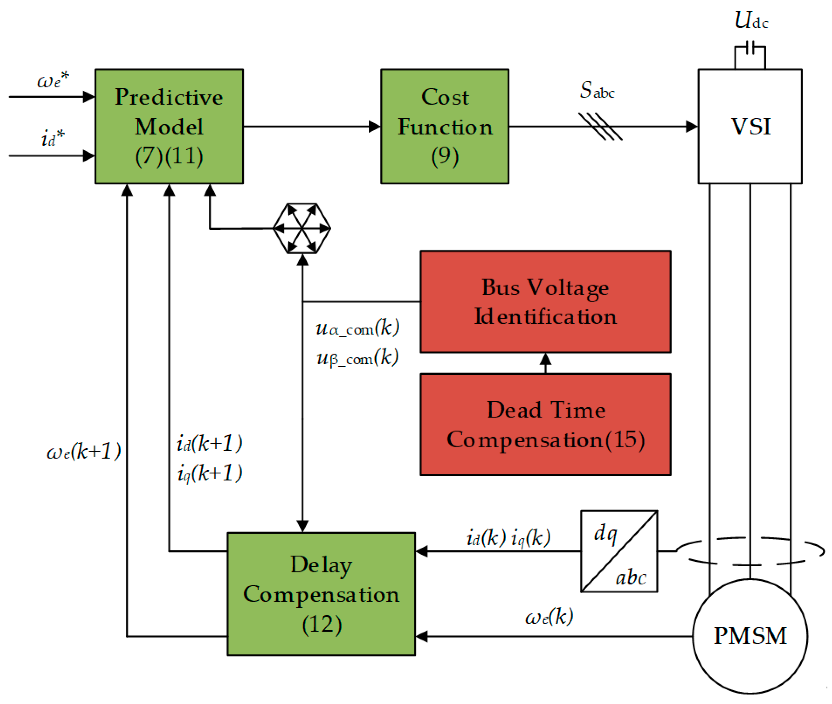
Figure 1 illustrates the structure of the proposed FCS-MPDSC.

3. Voltage Error Compensation

The accuracy of the mathematical model used directly impacts the performance of FCS-MPDSC. In a PMSM mathematical model, the current and speed are measured by sensors, and the parameters can be determined in advance, but there are few motor drive systems that measure candidate voltage vectors.
Therefore, this study investigated factors that contribute to voltage errors and explored their implications for FCS-MPDSC. Subsequently, a voltage error compensation method based on bus voltage identification is proposed to mitigate the influence of voltage errors.

3.1. Voltage Error Analysis

Typically, there exists a discrepancy between the theoretical voltage value calculated by an algorithm and the actual voltage applied to a motor, and one of the reasons for this discrepancy is the nonlinearity of the inverter. As shown in Formula (12), the nonlinearity of the inverter introduces errors in the candidate voltage vectors, u d ( k ) and u q ( k ) . Existing studies have found that when using traditional PWM modulation technology, the nonlinearity of the inverter is mainly caused by problems such as the dead-time effect and switch tube signal delay, and its dq-axis voltage errors are determined according to Formula (13):
{ u d _ r e a l ( k ) = u d ( k ) + Δ u d _ e r r o r i n v e r ( k ) u q _ r e a l ( k ) = u q ( k ) + Δ u q _ e r r o r i n v e r ( k )
{ Δ u d _ e r r o r i n v e r ( k ) = U d e a d D d Δ u q _ e r r o r i n v e r ( k ) = U d e a d D q
where u d _ r e a l ( k ) and u q _ r e a l ( k ) are the actual values; Δ u d _ e r r o r i n v e r ( k ) and Δ u q _ e r r o r i n v e r ( k ) are the voltage errors due to inverter nonlinearity; U d e a d is the magnitude of the voltage error; and D d and D q are the coefficients related to the electrical angle and the current direction.
In addition, it can be seen from Formula (6) that the candidate voltage vectors are related to Udc. When Udc fluctuates or the exact value of Udc cannot be obtained, the candidate voltage vectors will also have errors:
{ u d _ r e a l ( k ) = u d ( k ) + Δ u d _ e r r o r i n v e r ( k ) + Δ u d _ e r r o r b u s ( k ) u q _ r e a l ( k ) = u q ( k ) + Δ u q _ e r r o r i n v e r ( k ) + Δ u q _ e r r o r b u s ( k )
where Δ u d _ e r r o r b u s ( k ) and Δ u q _ e r r o r b u s ( k ) are the voltage errors caused by bus voltage uncertainties. The actual value of the bus voltage is U ^ dc = U dc + Δ U dc , and Δ U dc is the error of the bus voltage. The voltage errors of each voltage vector under the αβ-axis are shown in Table 1.

3.2. Voltage Error Impact on FCS-MPDSC

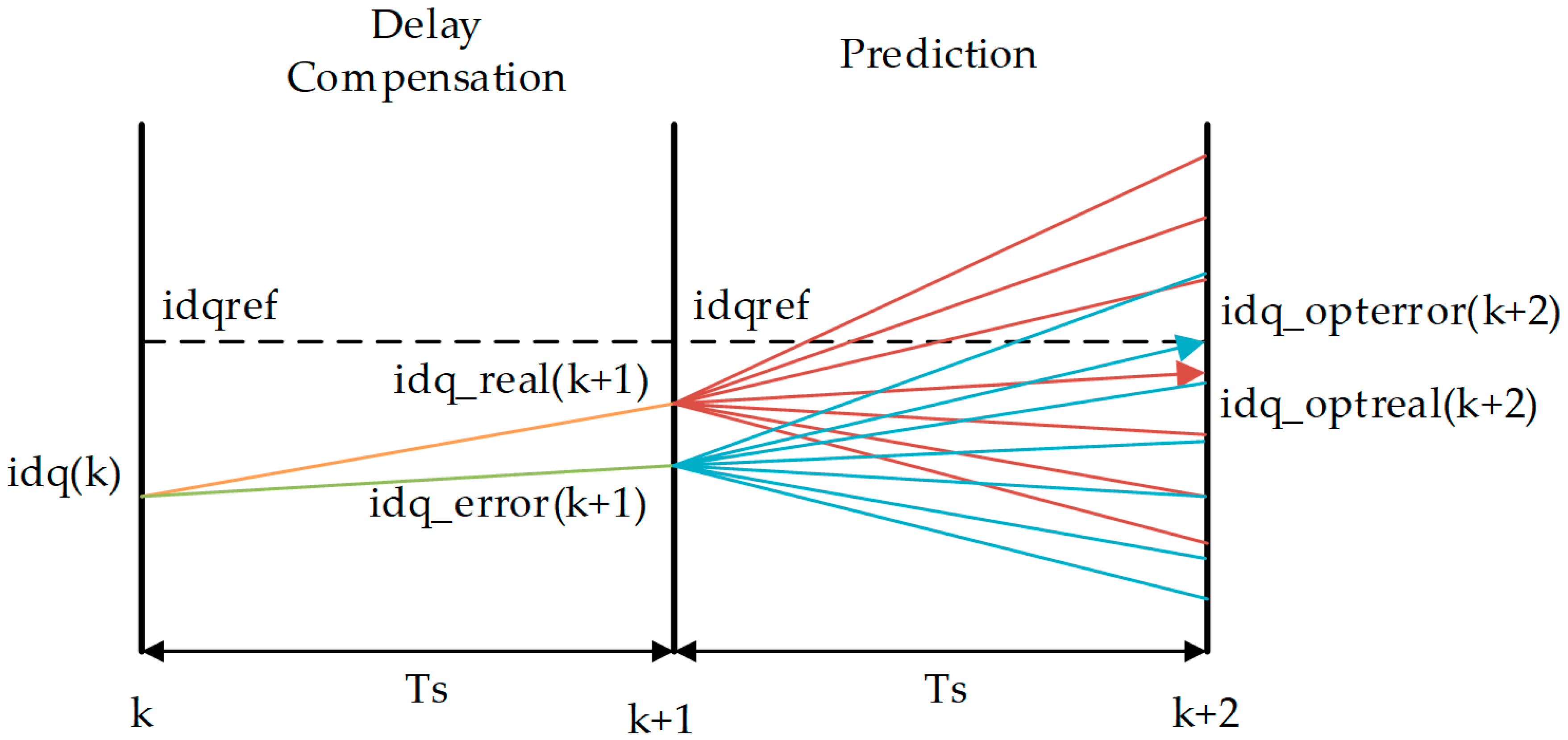
While FCS-MPDSC exhibits a degree of robustness to voltage vector errors, meaning it only needs to identify the optimal voltage vector rather than accurately calculate the output voltage value, significant voltage errors can still impact the selection of the optimal voltage vector. Additionally, the one-step delay compensation method further amplifies the influence of voltage errors on the predicted value, as illustrated in Figure 2.
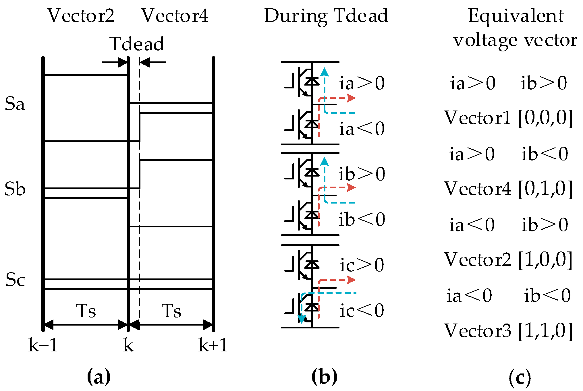
Unlike traditional PWM modulation technology, FCS-MPDSC does not have a dead zone in each sampling period. It is only when the switch states of two adjacent sampling moments are different that the system can set a dead zone. In Figure 3, the voltage vectors Vector 2 and Vector 4 are taken as examples. When the state of the a-bridge arm changes from 1 to 0, and the state of the b-bridge arm changes from 0 to 1, the system will set a dead zone, and the time is Tdead. When the state of the c-bridge arm is always 0, the system does not need to set a dead zone. The specific switching signal situation is shown in Figure 3a. During the period Tdead, the diodes corresponding to each phase current direction are activated, as depicted in Figure 3b. Hence, the voltage error resulting from inverter nonlinearity can be treated as an equivalent voltage vector, which is also among the eight fundamental voltage vectors. Figure 3c illustrates the equivalent voltage vectors for various combinations of phase currents.
As for the bus voltage error, because it exists in the six effective voltage vectors, its influence is more obvious for FCS-MPDSC.

3.3. Voltage Error Compensation Based on Bus Voltage Identification

To address the impact of voltage errors on FCS-MPC, this paper presents a voltage error compensation method based on bus voltage identification, which effectively compensates for voltage errors resulting from both inverter nonlinearity and bus voltage uncertainties.
Firstly, considering the voltage error resulting from inverter nonlinearity, it can be considered as an equivalent voltage vector applied during Tdead. The equivalent voltage vector and the candidate voltage vector are combined to form a compensatory candidate voltage vector, which is expressed as follows:
{ u α _ c o m ( k ) = 1 T d e a d T s u α ( k ) + T d e a d T s u α _ e q u ( k ) u β _ c o m ( k ) = 1 T d e a d T s u β ( k ) + T d e a d T s u β _ e q u ( k )
where u α _ e q u ( k ) and u β _ e q u ( k ) are the equivalent voltage vectors. Therefore, the voltage error generated by inverter nonlinearity will also be composed of basic voltage vectors. Based on the analysis in Section 3.1, it is evident that the basic voltage vectors are mainly caused by the bus voltage error. Therefore, the compensation for voltage errors caused by inverter nonlinearity and bus voltage fluctuations can be achieved by identifying the bus voltage.
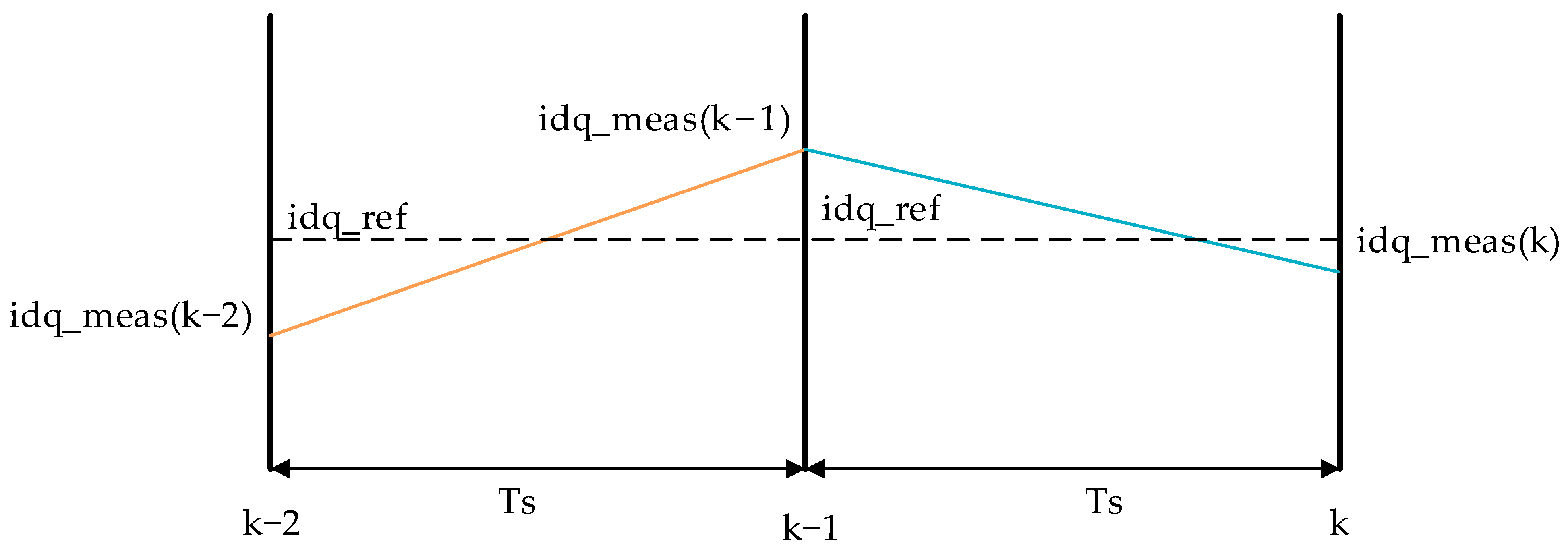
In this study, the recursive least squares (RLS) method was employed to estimate the bus voltage U ^ dc . As depicted in Figure 4, due to the application of only one voltage vector in each sampling period, the proposed FCS-MPDSC is unable to achieve zero-error control. Consequently, in two consecutive sampling periods, the rate of change in the motor current is non-zero, leading to variations in the motor’s states.
From Formula (15), the actual value of the dq-axis voltage can be obtained considering inverter nonlinearity and the error of the bus voltage as follows:
{ u d _ r e a l ( k ) = f d k ( θ e ( k ) ) U ^ d c u q _ r e a l ( k ) = f q k ( θ e ( k ) ) U ^ d c
where f d k ( θ e ( k ) ) and f q k ( θ e ( k ) ) are the voltage coefficients, which are determined by the optimal voltage vector and the equivalent voltage vector at moment k.
Taking the change rate of the motor current as a known variable and considering the parameter errors, the equation for the dq-axis voltage can be reformulated as follows:
{ 0 = i d ( k ) R ^ s + ( i q ( k ) ω e ( k ) d i d d t ( k ) ) L ^ + f d k ( θ e ( k ) ) U ^ d c 0 = i q ( k ) R ^ s ( i d ( k ) ω e ( k ) + d i q d t ( k ) ) L ^ ω e ( k ) ψ ^ f + f q k ( θ e ( k ) ) U ^ d c
where R ^ s , L ^ , and ψ ^ f are the actual parameters of PMSM.
Therefore, in addition to U ^ d c , there are three unknowns, namely R ^ s , L ^ , and ψ ^ f , but the equation set has a general solution where four unknowns are all zero. Considering that ψ ^ f can be obtained from the mechanical equation, it can be taken as a known quantity ψ f . Since only the q-axis voltage equation contains the term of ψ f , the RLS method is applied to solve for U ^ d c , R ^ s , and L ^ using only the q-axis equation. The modified equation is as follows:
ω e ( k ) ψ f = i q ( k ) R ^ s ( i d ( k ) ω e ( k ) + d i q d t ( k ) ) L ^ + f q k ( θ e ( k ) ) U ^ d c
Since three unknowns need to be solved, this study exploited the non-zero change rate of the motor current in FCS-MPC and combined the measured values of the past three moments to construct three equations with different coefficients to realize the bus voltage estimation based on RLS. Taking k moment as an example, by storing the state of the motor at moments k − 3, k − 2, and k − 1, the equations are as follows:
{ ω e ( k 3 ) ψ f = i q ( k 3 ) R ^ s ( i d ( k 3 ) ω e ( k 3 ) + d i q d t ( k 3 ) ) L ^ + f q k ( θ e ( k 3 ) ) U ^ d c ω e ( k 2 ) ψ f = i q ( k 2 ) R ^ s ( i d ( k 2 ) ω e ( k 2 ) + d i q d t ( k 2 ) ) L ^ + f q k ( θ e ( k 2 ) ) U ^ d c ω e ( k 1 ) ψ f = i q ( k 1 ) R ^ s ( i d ( k 1 ) ω e ( k 1 ) + d i q d t ( k 1 ) ) L ^ + f q k ( θ e ( k 1 ) ) U ^ d c
The state matrices of RLS are as follows:
y ( k ) = [ ω e ( k 3 ) ψ f ω e ( k 2 ) ψ f ω e ( k 1 ) ψ f ] T
θ ( k ) = [ R ^ s ( k ) L ^ ( k ) U ^ d c ( k ) ] T
φ ( k ) = [ i q ( k 3 ) i d ( k 3 ) ω e ( k 3 ) d i q d t ( k 3 ) f q k 2 ( θ e ( k 3 ) ) i q ( k 2 ) i d ( k 2 ) ω e ( k 2 ) d i q d t ( k 2 ) f q k 2 ( θ e ( k 2 ) ) i q ( k 1 ) i d ( k 1 ) ω e ( k 1 ) d i q d t ( k 1 ) f q k 1 ( θ e ( k 1 ) ) ] T
e ( k ) = y ( k ) φ T ( k ) θ ( k )
The RLS equations are as follows:
K ( k ) = P ( k 1 ) φ ( k ) [ λ I + φ T ( k ) P ( k 1 ) φ ( k ) ] 1
P ( k ) = [ I K ( k ) θ T ( k ) ] λ 1 P ( k 1 )
θ ( k ) = θ ( k 1 ) + K ( k ) e ( k )
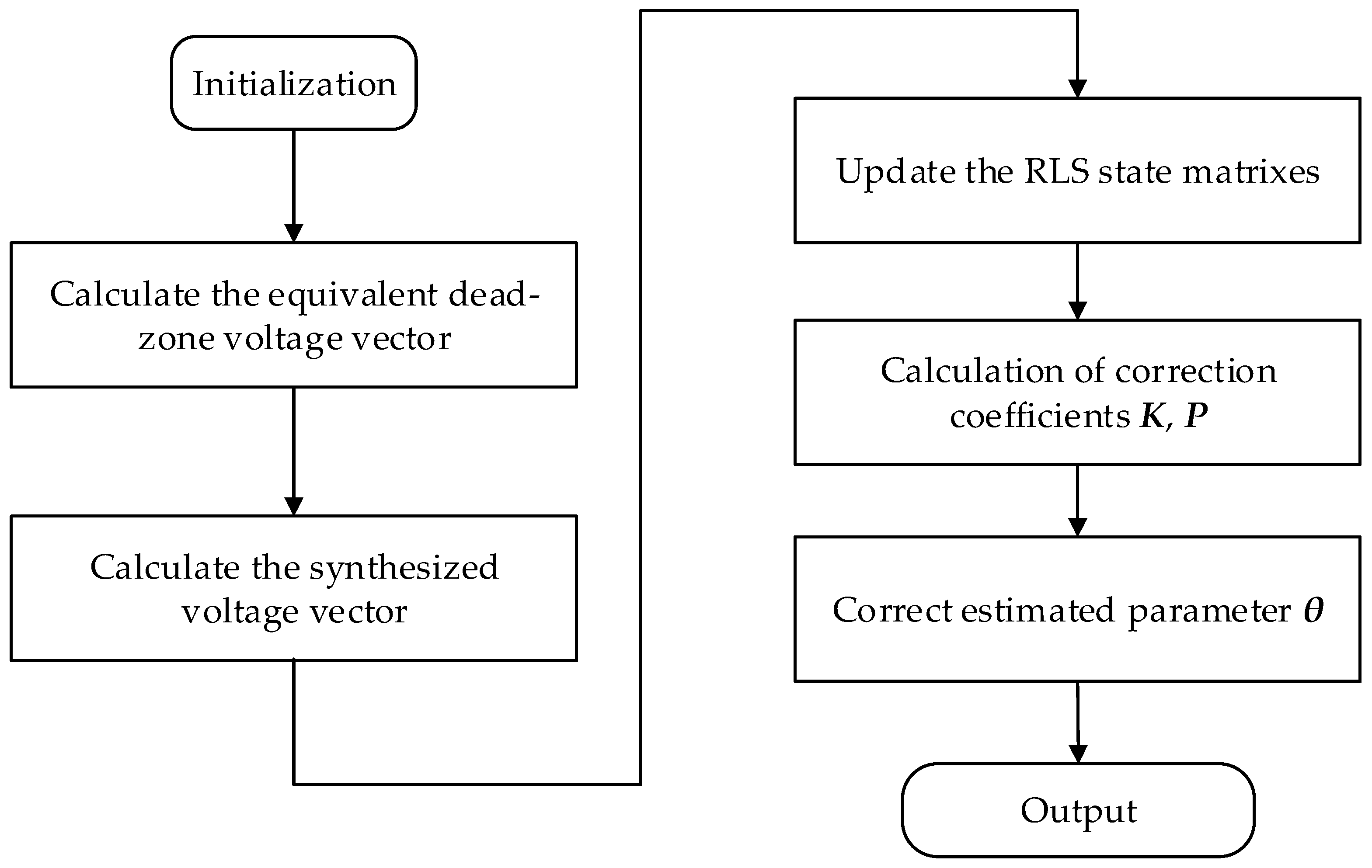
Figure 5 illustrates the flowchart of bus voltage identification based on RLS.
This strategy first calculates the equivalent dead-zone voltage vector, which is zero if the switch state does not change. Then, according to the current, speed measurements, and voltage vector coefficients of the past three moments, the state matrices y and φ of RLS are updated, the correction coefficient matrices K and P are calculated, and, finally, the corrected estimated parameter θ is output. After obtaining the estimated value of the bus voltage, this study adopted the voltage feedforward compensation strategy to correct the voltage vector error, and its control principle is shown in Figure 6.

4. Experimental Results

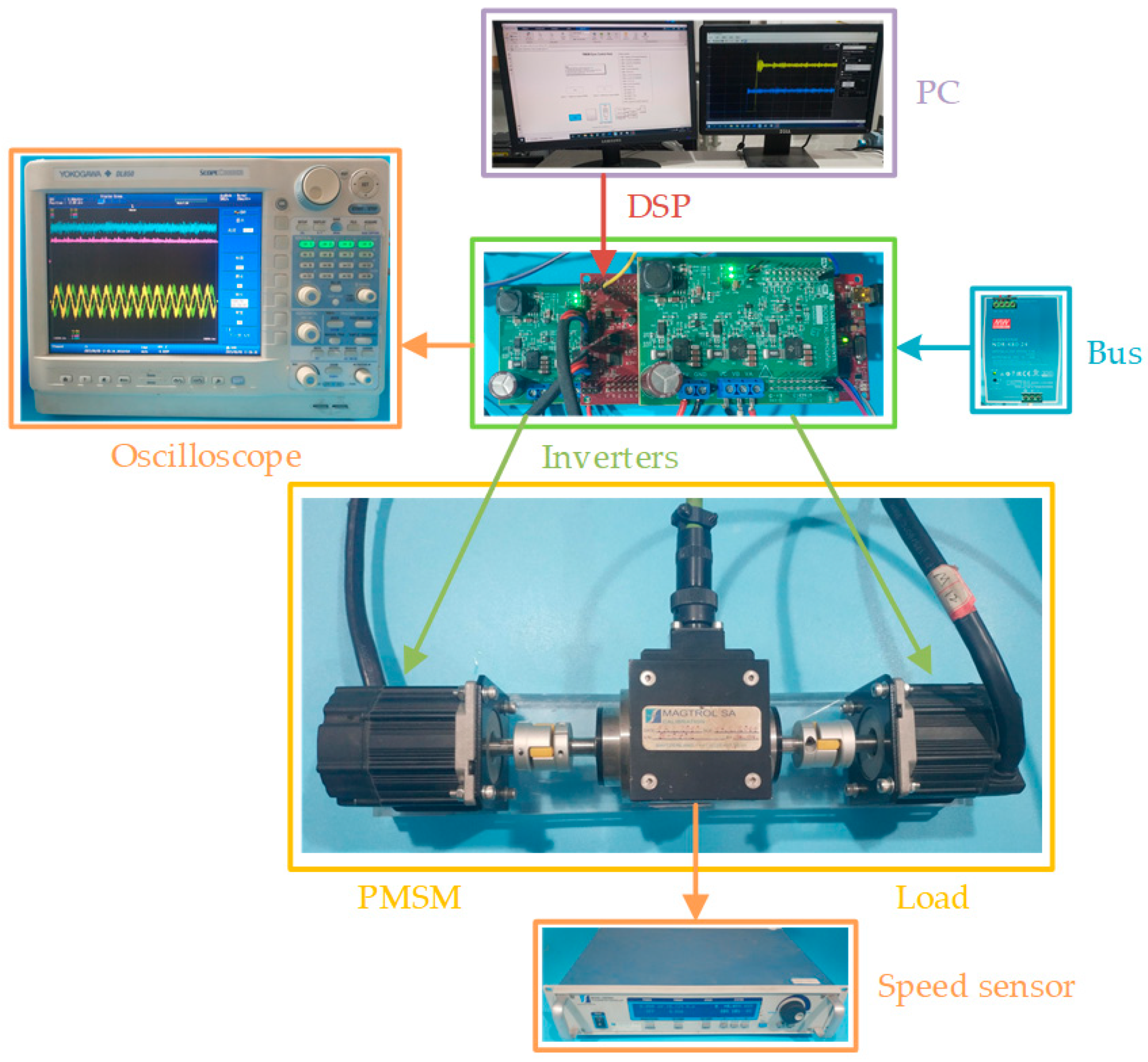
The experimental setup is depicted in Figure 7. The controller uses TI’s DSP evaluation board LAUNCHXL-F28379D, the drivers use GaN-based BOOSTXL-3PhGaNInv, and the PMSMs are Teknic’s M-2310P-LN-04K. The parameters are presented in Table 2.
To verify the proposed voltage error compensation strategy, this study compared an FCS-MPDSC without voltage compensation (FCS-MPDSC without VC) [13], a FCS-MPDSC with centralized disturbance compensation (FCS-MPDSC with CDC) [43], and the proposed FCS-MPDSC with bus voltage compensation. The FCS-MPDSC without VC is the traditional strategy without any voltage compensation method. The FCS-MPDSC with CDC observes and compensates for voltage errors and parameter errors using centralized disturbance terms. In this study, all three strategies were utilized to conduct motor control experiments under the influence of inverter nonlinearity, bus voltage errors, and parameter errors. The experimental results were then numerically compared with the results obtained using the three strategies. In the experiment, the dq-axis current data were the output given by the DAC that comes with DSPF28379D, and these data were collected using an oscilloscope together with the phase current waveforms; the rotational speed data were collected using the software of Magtrol through the speed sensor.
In this study, we primarily compared the experimental results of the different control strategies using two metrics. The first metric is the steady-state error of the speed response, which is calculated using the following formula:
Δ n = n r e f n a v e r a g e
where n r e f is the velocity reference value, and n a v e r a g e is the average value of the speed steady-state response. In this study, the speed reference value was set to 1000 r/min. The average value of the speed steady-state response was obtained using the mean function in MATLAB.
The second metric is the total harmonic distortion (THD), which is calculated using the following formula:
V a l u e T H D = ( I 2 ) 2 + ( I 3 ) 2 + ( I 4 ) 2 + + ( I n ) 2 ( I 1 ) 2
where I 1 is the root mean square (RMS) value of the fundamental component of the phase current, and I n are the RMS values of the harmonic components of the phase current. In this study, the fundamental frequency of the phase current was set to 66.667 Hz. The RMS values of the various frequency components of the phase current were obtained using the FFT function in MATLAB.

4.1. Inverter Nonlinearity

The motor system was given the following reference values: a speed reference value of 1000 r/min, a load torque of 0.2 Nm, and a dead time of 1 μs.
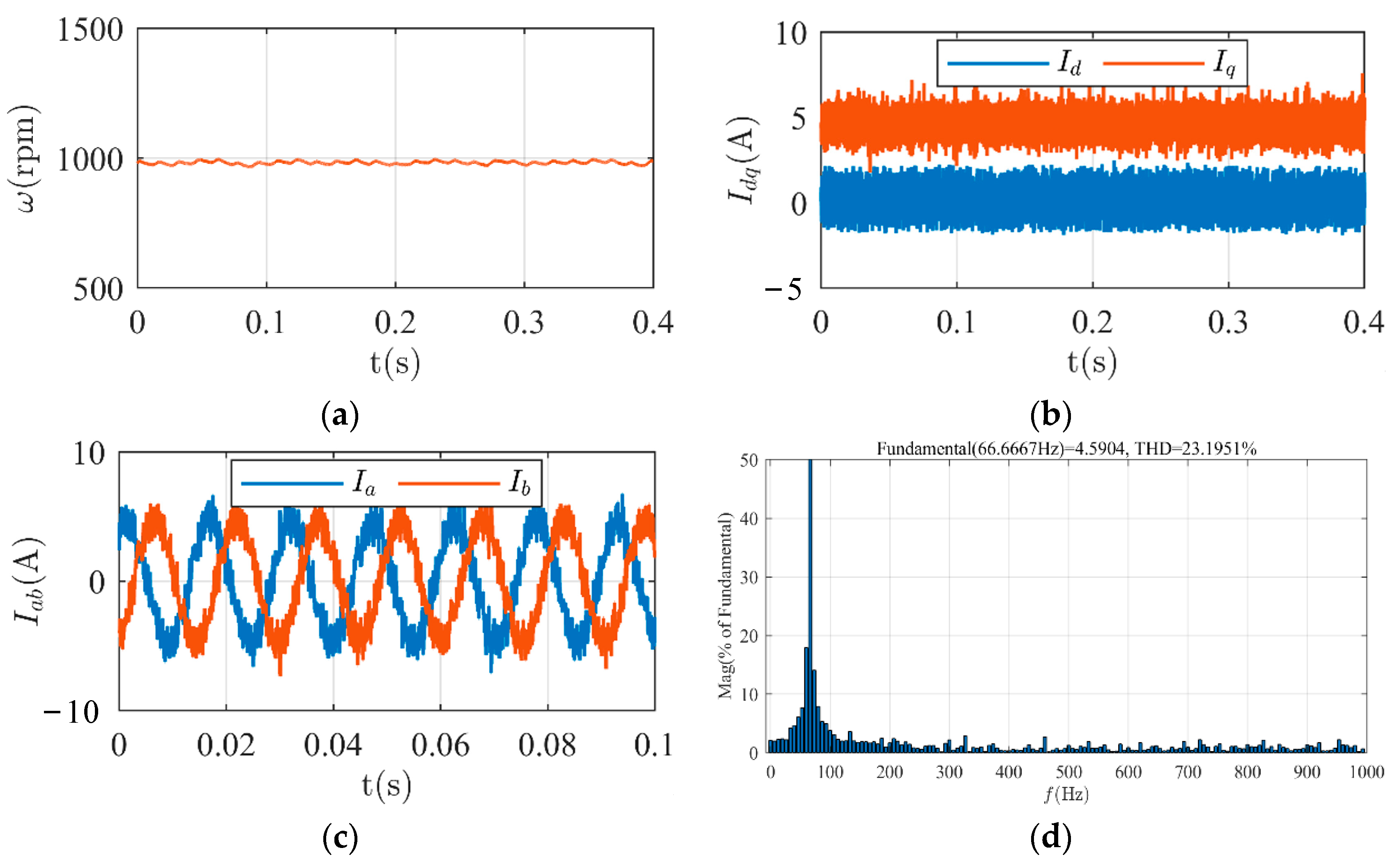
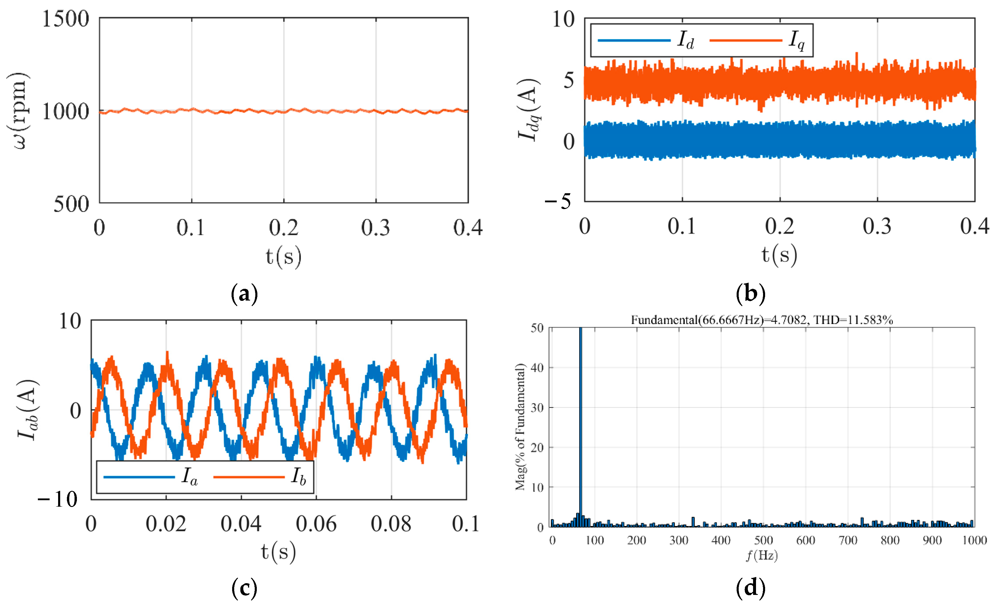
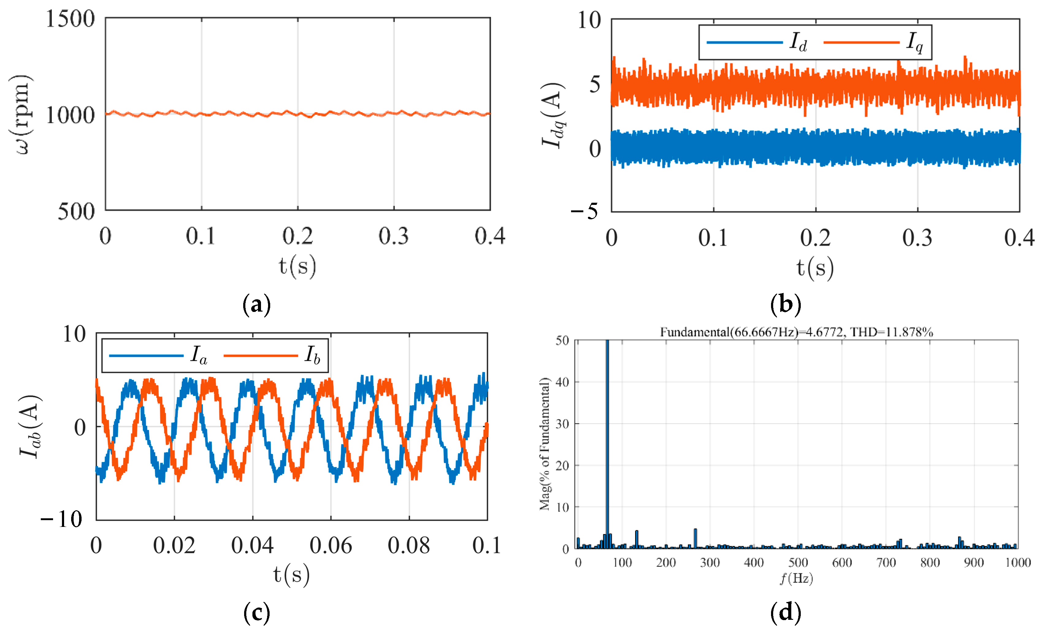
The experimental results of the three control strategies after the motor had reached a steady state are presented in Figure 8, Figure 9 and Figure 10. In Figure 8a, Figure 9a and Figure 10a, without compensation for the voltage error caused by inverter nonlinearity, a small steady-state error in speed occurs, which is approximately 10 r/min. However, both the FCS-MPDSC with CDC and the proposed FCS-MPDSC exhibit almost no steady-state error. Figure 8b, Figure 9b and Figure 10b display the dq-axis currents for the three control strategies. Compared to the current waveforms under the FCS-MPDSC without VC, both the FCS-MPDSC with CDC and the proposed FCS-MPDSC reduce current fluctuations. Figure 8c,d, Figure 9c,d and Figure 10c,d illustrate the waveforms of phase currents ia and ib, as well as the fast Fourier transform (FFT) results of ia. The total harmonic distortion (THD) of phase current ia is 23.2% under the FCS-MPDSC without VC, while the THD of current ia is reduced to 10.1% and 11.6% under the FCS-MPDSC with CDC and the proposed FCS-MPDSC, respectively. These results demonstrate that the proposed FCS-MPDSC can compensate for the voltage error caused by inverter nonlinearity, similar to the effect achieved by the FCS-MPDSC with CDC.

4.2. Bus Voltage Error

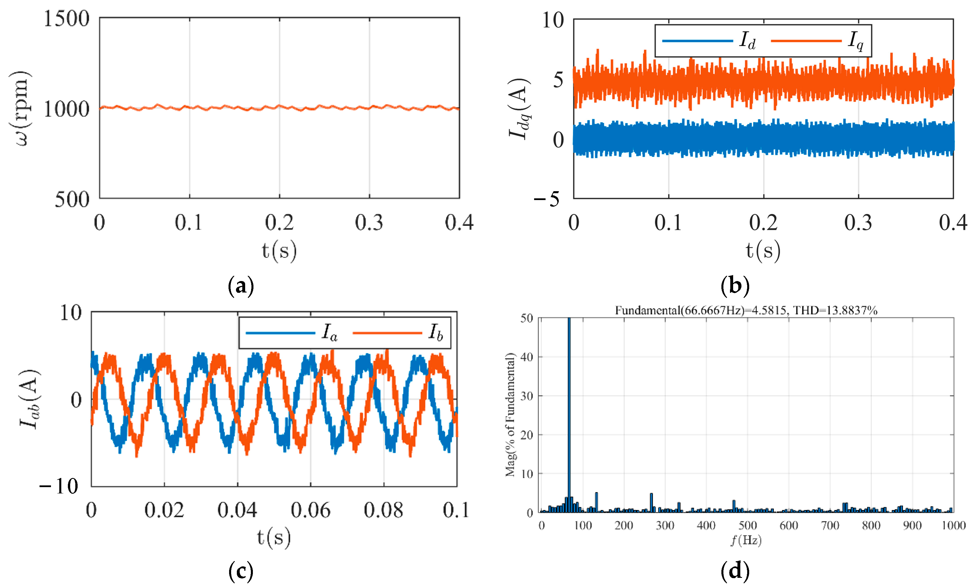
In this experiment, the motor was set to operate under the same conditions as those with inverter nonlinearity, but there was a 5V error in the bus voltage value. The experimental waveforms for the three control strategies are presented in Figure 11, Figure 12 and Figure 13. As shown in Figure 11a, Figure 12a and Figure 13a, the bus voltage error leads to a steady-state error of approximately 40 r/min in speed under FCS-MPDSC without VC. However, both the FCS-MPDSC with CDC and the proposed FCS-MPDSC maintain the motor speed effectively. Figure 11b–d, Figure 12b–d and Figure 13b–d display the motor’s dq-axis currents, phase currents, and FFT results. The bus voltage error significantly affects the motor’s current under the FCS-MPDSC without VC. The dq-axis current fluctuation becomes larger than when only dealing with voltage error caused by inverter nonlinearity, and the THD of the phase current reaches 49.6%. In this scenario, both the FCS-MPDSC with CDC and the proposed FCS-MPDSC effectively mitigate the influence of bus voltage errors. The THD of the phase current is reduced to 11.9% under the FCS-MPDSC with CDC, while it is reduced to 13.9% under the proposed FCS-MPDSC. These results demonstrate that when the parameters are accurate, the proposed FCS-MPDSC can effectively suppress voltage errors, achieving a similar suppression effect as the FCS-MPDSC with CDC.

4.3. Parameter Errors

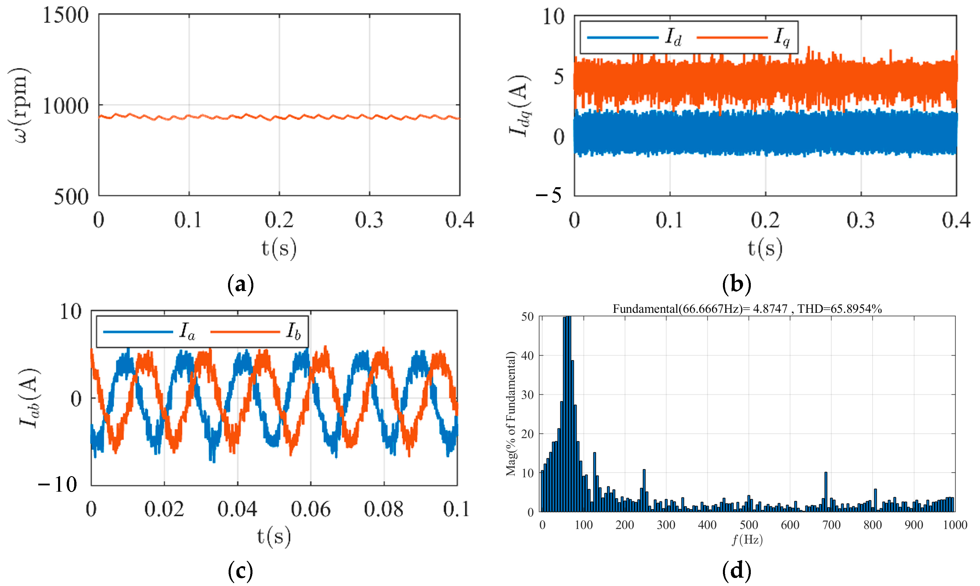
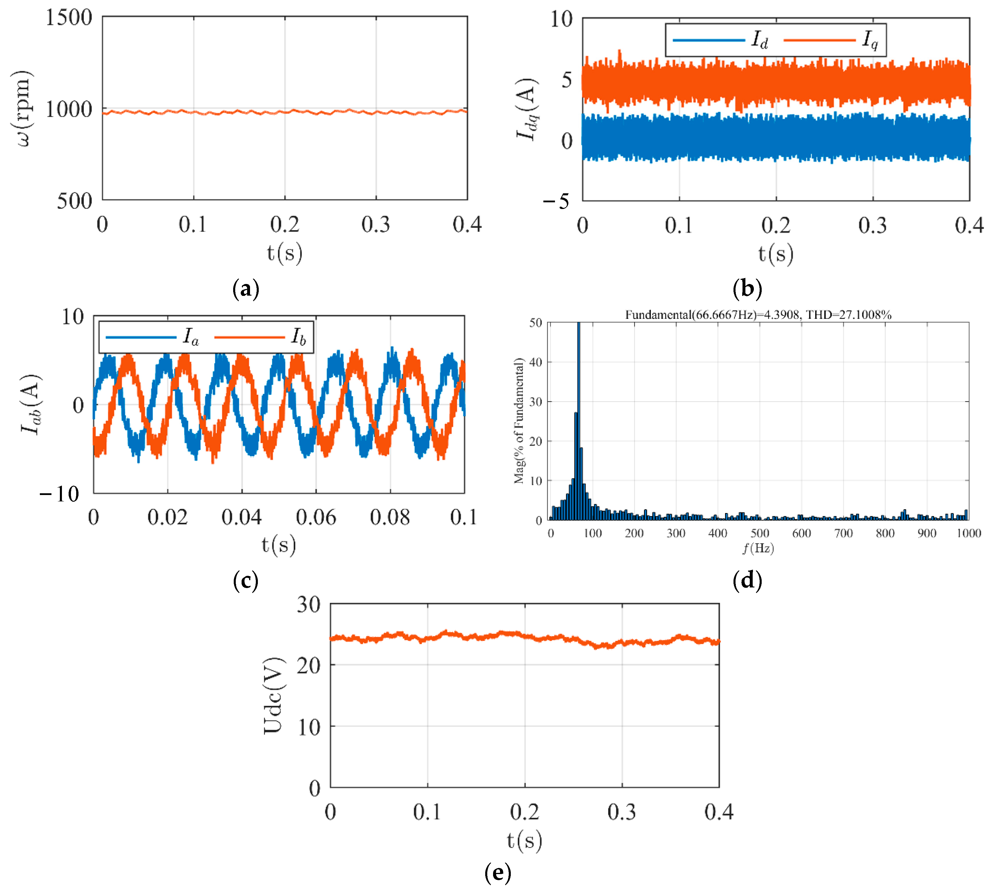
Next, we investigated not only the voltage error resulting from inverter nonlinearity and bus voltage uncertainty, but also errors in the parameters. The motor was set to operate under the same conditions as in the previous experiment, with the motor’s parameters assumed to be twice their actual values. The experimental results are presented in Figure 14, Figure 15 and Figure 16. Figure 14a shows that due to the introduction of parameter errors, the steady-state error in speed further increases to 70 r/min under the FCS-MPDSC without VC. In Figure 15a, the FCS-MPDSC with CDC is still capable of controlling the motor speed effectively. However, the proposed FCS-MPDSC cannot compensate for parameter errors, resulting in a steady-state speed error of 30 r/min, as shown in Figure 16a. The current experimental results depicted in Figure 14b–d, Figure 15b–d and Figure 16b–d indicate that the THD of ia under the FCS-MPDSC without VC rises to 65.9%. In contrast, the THD of ia under the FCS-MPDSC with CDC remains at 14.1%, while the THD of ia under the proposed FCS-MPDSC reaches 27.1%. However, the bus voltage error observation strategy based on RLS can accurately observe the actual bus voltage value, as shown in Figure 16e.
Table 3 presents a comprehensive summary of all of the metrics obtained from the experimental results using the three different strategies. The experimental results validate the effectiveness of our proposed strategy. The strategy successfully mitigates the adverse effects of voltage errors, leading to improved speed-tracking accuracy and reduced THD in phase currents. Specifically, our method achieves a significant reduction in THD, lowering it from 23.2% (with inverter nonlinearity) and 49.6% (with bus voltage error) to 11.6% and 13.9%, respectively. Although the proposed FCS-MPDSC cannot suppress parameter errors, it can obtain precise voltage values, which is beneficial for further research on other algorithms, such as parameter identification and efficiency calculation.
Table 4 provides the percentage magnitude of the fifth- and seventh-harmonic components of the phase current under the three different strategies. It is evident that the proposed FCS-MPDSC successfully mitigates the amplitude of the harmonic components in the phase current caused by voltage errors. The amplitudes of the fifth harmonic and the seventh harmonic decrease from 2.9% and 2.7% (with inverter nonlinearity), and from 7.6% and 6.0% (with bus voltage error), to 1.4% and 1.7%, and to 1.5% and 1.9%, respectively.

5. Conclusions

In conclusion, this study proposes a voltage-error-compensation-based model predictive direct speed control (MPDSC) strategy for addressing the impact of voltage errors in PMSM systems. Through a comprehensive analysis of voltage errors arising from inverter nonlinearity and bus voltage uncertainties, we identified that these errors can be effectively compensated using bus voltage identification. To achieve this, we designed an identification strategy based on recursive least squares (RLS) and the current rate of change. The experimental results validate the effectiveness of our proposed strategy. The strategy successfully mitigates the adverse effects of voltage errors, leading to improved speed-tracking accuracy and reduced total harmonic distortion (THD) in phase currents. Specifically, our method achieves a significant reduction in THD, lowering it from 23.2% (with inverter nonlinearity) and 49.6% (with bus voltage error) to 11.6% and 13.9%, respectively. Among them, the amplitude of the fifth harmonic and the seventh harmonic decreases from 2.9% and 2.7% (with inverter nonlinearity), and from 7.6% and 6.0% (with bus voltage error), to 1.4% and 1.7%, and to 1.5% and 1.9%, respectively. Furthermore, an important advantage of our strategy is its identification of precise voltage values with parameter errors. This capability enhances the stability and performance of the MPDSC system. In summary, our voltage-error-compensation-based MPDSC strategy offers a promising solution for addressing voltage errors in PMSM systems. It effectively improves speed-tracking accuracy, reduces THD in phase currents, and exhibits robustness against parameter errors. The experimental results provide strong evidence of the effectiveness and practicality of our proposed strategy.

Author Contributions

Conceptualization, L.G.; methodology, L.G.; software, L.G.; validation, L.G.; formal analysis, L.G.; investigation, L.G.; resources, L.G.; data curation, L.G.; writing—original draft preparation, L.G.; writing—review and editing, L.G.; visualization, L.G.; supervision, F.C.; project administration, F.C.; funding acquisition, F.C. All authors have read and agreed to the published version of the manuscript.

Funding

This research was funded by the National Natural Science Foundation of China, grant number 52177031.

Data Availability Statement

Not applicable.

Conflicts of Interest

The authors declare no conflict of interest.

References

  1. Song, Z.; Dong, Z.; Wang, W.; Liu, S.; Liu, C. A Novel Modulation Strategy for Asymmetrical Six-Phase Series-Winding PMSM Based on Predictive Controller. IEEE Trans. Ind. Electron. 2023, 70, 5592–5603. [Google Scholar] [CrossRef]
  2. Song, Z.; Huang, R.; Wang, W.; Dong, Z.; Liu, C. Harmonic Current Control of OW-PMSM for Low-Voltage Traction by Nonlinear Disturbance Rejection with Improved Modulation Scheme. IEEE Trans. Veh. Technol. 2023, 72, 3119–3131. [Google Scholar] [CrossRef]
  3. Liu, S.; Song, Z.; Dong, Z.; Liu, Y.; Liu, C. Generic Carrier-Based PWM Solution for Series-End Winding PMSM Traction System with Adaptative Overmodulation Scheme. IEEE Trans. Transp. Electrif. 2023, 9, 712–726. [Google Scholar] [CrossRef]
  4. Liu, S.; Song, Z.; Liu, Y.; Chen, Y.; Liu, C. Flux-Weakening Controller Design of Dual Three-Phase PMSM Drive System with Copper Loss Minimization. IEEE Trans. Power Electron. 2023, 38, 2351–2363. [Google Scholar] [CrossRef]
  5. Chen, Y.; Liu, C.; Liu, S.; Song, Z. A New Cascaded Adaptive Deadbeat Control Method for PMSM Drive. IEEE Trans. Ind. Electron. 2023, 70, 3384–3393. [Google Scholar] [CrossRef]
  6. Wu, Z.; Yang, Z.; Ding, K.; He, G. Transfer Mechanism Analysis of Injected Voltage Harmonic and its Effect on Current Harmonic Regulation in FOC PMSM. IEEE Trans. Power Electron. 2022, 37, 820–829. [Google Scholar] [CrossRef]
  7. Nguyen, T.H.; Nguyen, T.T.; Nguyen, V.Q.; Le, K.M.; Tran, H.N.; Jeon, J.W. An Adaptive Sliding-Mode Controller with a Modified Reduced-Order Proportional Integral Observer for Speed Regulation of a Permanent Magnet Synchronous Motor. IEEE Trans. Ind. Electron. 2022, 69, 7181–7191. [Google Scholar] [CrossRef]
  8. Yang, L.; Li, H.; Huang, J.; Zhang, Z.; Zhao, H. Model Predictive Direct Speed Control with Novel Cost Function for SMPMSM Drives. IEEE Trans. Power Electron. 2022, 37, 9586–9595. [Google Scholar] [CrossRef]
  9. Zhang, X.; Zhao, Z.; Xu, C. A Flux-Weakening Method for PMSM Based Model Predictive Direct Speed Control. In Proceedings of the 2020 IEEE 9th International Power Electronics and Motion Control Conference (IPEMC2020-ECCE Asia), Nanjing, China, 29 November–2 December 2020; pp. 2557–2561. [Google Scholar] [CrossRef]
  10. He, C.; Hu, J.; Li, Y. Predictive Position Control with System Constraints for PMSM Drives Based on Geometric Optimization. IEEE Trans. Ind. Electron. 2023, 70, 7773–7782. [Google Scholar] [CrossRef]
  11. Kakosimos, P.; Abu-Rub, H. Predictive Speed Control with Short Prediction Horizon for Permanent Magnet Synchronous Motor Drives. IEEE Trans. Power Electron. 2018, 33, 2740–2750. [Google Scholar] [CrossRef]
  12. Kawai, H.; Zhang, Z.; Kennel, R.; Doki, S. Direct Speed Control Based on Finite Control Set Model Predictive Control with Voltage Smoother. IEEE Trans. Ind. Electron. 2023, 70, 2363–2372. [Google Scholar] [CrossRef]
  13. Xu, Y.; Ren, J.; Fan, L.; Yin, Z. Multidisturbance Suppressed Model Predictive Direct Speed Control with Low Pulsation for PMSM Drives. IEEE J. Emerg. Sel. Top. Power Electron. 2022, 10, 6135–6147. [Google Scholar] [CrossRef]
  14. Gong, C.; Hu, Y.; Ni, K.; Liu, J.; Gao, J. SM Load Torque Observer-Based FCS-MPDSC With Single Prediction Horizon for High Dynamics of Surface-Mounted PMSM. IEEE Trans. Power Electron. 2020, 35, 20–24. [Google Scholar] [CrossRef]
  15. Mao, J.; Li, H.; Yang, L.; Zhang, H.; Liu, L.; Wang, X.; Tao, J. Non-Cascaded Model-Free Predictive Speed Control of SMPMSM Drive System. IEEE Trans. Energy Convers. 2022, 37, 153–162. [Google Scholar] [CrossRef]
  16. Wang, Q.; Wang, G.; Zhao, N.; Zhang, G.; Cui, Q.; Xu, D. An Impedance Model-Based Multiparameter Identification Method of PMSM for Both Offline and Online Conditions. IEEE Trans. Power Electron. 2021, 36, 727–738. [Google Scholar] [CrossRef]
  17. Wang, Y.; Xu, Y.; Zou, J. Sliding-Mode Sensorless Control of PMSM With Inverter Nonlinearity Compensation. IEEE Trans. Power Electron. 2019, 34, 10206–10220. [Google Scholar] [CrossRef]
  18. Zhao, H.Q.; Wu, M.J.; Kawamura, A. An accurate approach of nonlinearity compensation for VSI inverter output voltage. IEEE Trans. Power Electron. 2004, 19, 1029–1035. [Google Scholar] [CrossRef]
  19. Zhou, S.; Liu, K.; Wu, J.; Li, K.; Huang, C.; Zhang, D. Differential-Mode Circulating Current Suppression for Paralleled Inverters Fed PMSM Drives Considering Dead Time Compensation. IEEE Trans. Power Electron. 2023, 38, 8742–8753. [Google Scholar] [CrossRef]
  20. Park, D.-M.; Kim, K.-H. Parameter-Independent Online Compensation Scheme for Dead Time and Inverter Nonlinearity in IPMSM Drive Through Waveform Analysis. IEEE Trans. Ind. Electron. 2014, 61, 701–707. [Google Scholar] [CrossRef]
  21. Pengcheng, D.; Dianguo, X.; Bo, W.; Yong, Y. Offline Parameter Identification Strategy of Permanent Magnet Synchronous Motor Considering the Inverter Nonlinearities. In Proceedings of the 2022 25th International Conference on Electrical Machines and Systems (ICEMS), Chiang Mai, Thailand, 29 November–2 December 2022; pp. 1–5. [Google Scholar] [CrossRef]
  22. Pei, L.; Li, L.; Liu, J.; Cheng, Z.; Guo, Q.; Liu, H. A Robust Deadzone Compensation Method Against Parameter Variations based on Kalman Filter and Neural Networks. In Proceedings of the IECON 2021—47th Annual Conference of the IEEE Industrial Electronics Society, Toronto, ON, Canada, 13–16 October 2021; pp. 1–6. [Google Scholar] [CrossRef]
  23. Inoue, Y.; Morimoto, S.; Sanada, M. Comparative Study on Dead-time Compensation for Improvement of Starting Characteristic in High Speed PMSM Drive System. In Proceedings of the 2022 25th International Conference on Electrical Machines and Systems (ICEMS), Chiang Mai, Thailand, 29 November–2 December 2022; pp. 1–5. [Google Scholar] [CrossRef]
  24. Li, T.; Liang, C.; Su, D. UKF-based Offline Estimation of PMSM Magnet Flux Linkage Considering Inverter Dead-time Voltage Error. In Proceedings of the 2022 IEEE Applied Power Electronics Conference and Exposition (APEC), Houston, TX, USA, 20–24 March 2022; pp. 145–152. [Google Scholar] [CrossRef]
  25. Liu, K.; Zhu, Z.Q. Online Estimation of the Rotor Flux Linkage and Voltage-Source Inverter Nonlinearity in Permanent Magnet Synchronous Machine Drives. IEEE Trans. Power Electron. 2014, 29, 418–427. [Google Scholar] [CrossRef] [Green Version]
  26. Hwang, S.-H.; Kim, J.-M. Dead Time Compensation Method for Voltage-Fed PWM Inverter. IEEE Trans. Energy Convers. 2010, 25, 1–10. [Google Scholar] [CrossRef]
  27. Kim, H.-S.; Moon, H.-T.; Youn, M.-J. On-line dead-time compensation method using disturbance observer. IEEE Trans. Power Electron. 2003, 18, 1336–1345. [Google Scholar] [CrossRef]
  28. Zhang, Q.; Fan, Y. The Online Parameter Identification Method of Permanent Magnet Synchronous Machine under Low-Speed Region Considering the Inverter Nonlinearity. Energies 2022, 15, 4314. [Google Scholar] [CrossRef]
  29. Chen, H.; Yao, Z.; Liu, Y.; Lin, J.; Wang, P.; Gao, J.; Zhu, S.; Zhou, R. PMSM Adaptive Sliding Mode Controller Based on Improved Linear Dead Time Compensation. Actuators 2022, 11, 267. [Google Scholar] [CrossRef]
  30. Wang, H.; Zheng, X.; Yuan, X.; Wu, X. Low-Complexity Model-Predictive Control for a Nine-Phase Open-End Winding PMSM With Dead-Time Compensation. IEEE Trans. Power Electron. 2022, 37, 8895–8908. [Google Scholar] [CrossRef]
  31. Jin, S.; Zhang, W.; Liu, Z.; Xie, F.; Xu, Y.; Zou, J. Direct-axis Dead-time Effect Compensation Strategy Based on Adaptive Linear Neuron Method for PMSM Drives. In Proceedings of the IECON 2022—48th Annual Conference of the IEEE Industrial Electronics Society, Brussels, Belgium, 17–20 October 2022; pp. 1–6. [Google Scholar] [CrossRef]
  32. Son, D.-I.; Han, J.-S.; Park, J.-S.; Lim, H.-S.; Lee, G.-H. Performance Improvement of DTC-SVM of PMSM with Compensation for the Dead Time Effect and Power Switch Loss Based on Extended Kalman Filter. Electronics 2023, 12, 966. [Google Scholar] [CrossRef]
  33. Li, F.; Luo, Y.; Luo, X.; Chen, P.; Chen, Y. Optimal FOPI Error Voltage Control Dead-Time Compensation for PMSM Servo System. Fractal Fract. 2023, 7, 274. [Google Scholar] [CrossRef]
  34. Chen, Z.; Qiu, J.; Jin, M. Adaptive finite-control-set model predictive current control for IPMSM drives with inductance variation. IET Electr. Power Appl. 2017, 11, 874–884. [Google Scholar] [CrossRef]
  35. Brosch, A.; Hanke, S.; Wallscheid, O.; Böcker, J. Data-Driven Recursive Least Squares Estimation for Model Predictive Current Control of Permanent Magnet Synchronous Motors. IEEE Trans. Power Electron. 2021, 36, 2179–2190. [Google Scholar] [CrossRef]
  36. Yang, M.; Yang, K.; Li, G.; Yi, C.; Xu, D. A Novel Dead-Time Compensation Method for Direct Predictive Control. In Proceedings of the 2015 Fifth International Conference on Instrumentation and Measurement, Computer, Communication and Control (IMCCC), Qinhuangdao, China, 18–20 September 2015; pp. 273–277. [Google Scholar] [CrossRef]
  37. Fuentes, E.J.; Silva, C.; Quevedo, D.E.; Silva, E.I. Predictive speed control of a synchronous permanent magnet motor. In Proceedings of the 2009 IEEE International Conference on Industrial Technology, Gippsland, Australia, 10–13 February 2009; pp. 1–6. [Google Scholar] [CrossRef]
  38. Zhang, X.; Cheng, Y.; Zhao, Z.; Yan, K. Optimized Model Predictive Control with Dead-Time Voltage Vector for PMSM Drives. IEEE Trans. Power Electron. 2021, 36, 3149–3158. [Google Scholar] [CrossRef]
  39. Xue, Z.; Niu, S.; Li, X. A Simplified Multi-Vector-Based Model Predictive Current Control for PMSM with Enhanced Performance. IEEE Trans. Transp. Electrif. 2023. Early Access. [Google Scholar] [CrossRef]
  40. Sun, X.; Zhang, Y.; Cai, Y.; Tian, X. Compensated Deadbeat Predictive Current Control Considering Disturbance and VSI Nonlinearity for In-Wheel PMSMs. IEEE/ASME Trans. Mechatron. 2022, 27, 3536–3547. [Google Scholar] [CrossRef]
  41. Li, Y.; Zhang, Z.; Li, K.; Zhang, P.; Gao, F. Predictive current control for voltage source inverters considering dead-time effect. CES Trans. Electr. Mach. Syst. 2020, 4, 35–42. [Google Scholar] [CrossRef]
  42. Li, J.; Song, W.; Yue, H.; Sun, N.; Ma, C.; Feng, R. An Improved MPC With Reduced CMV and Current Distortion for PMSM Drives Under Variable DC-Bus Voltage Condition in Electric Vehicles. IEEE Trans. Power Electron. 2023, 38, 5167–5177. [Google Scholar] [CrossRef]
  43. Zhang, X.; Cheng, Y.; Zhao, Z.; He, Y. Robust Model Predictive Direct Speed Control for SPMSM Drives Based on Full Parameter Disturbances and Load Observer. IEEE Trans. Power Electron. 2020, 35, 8361–8373. [Google Scholar] [CrossRef]
  44. Li, S.; Xu, Y.; Zhang, W.; Zou, J. Robust Deadbeat Predictive Direct Speed Control for PMSM With Dual Second-Order Sliding-Mode Disturbance Observers and Sensitivity Analysis. IEEE Trans. Power Electron. 2023, 38, 8310–8326. [Google Scholar] [CrossRef]
  45. Abbasimoshaei, A.; Stein, T.; Rothe, T.; Kern, T.A. Design and impedance control of a hydraulic robot for paralyzed people. In Proceedings of the 8th RSI International Conference on Robotics and Mechatronics, ICRoM 2020, Online, Iran, 19 November 2020; Available online: https://icrom.ir/wp-content/uploads/2020/12/17-revised.pdf (accessed on 17 December 2020).
  46. Wang, Y.; Xu, Y.; Zou, J. ILC-Based Voltage Compensation Method for PMSM Sensorless Control Considering Inverter Nonlinearity and Sampling Current DC Bias. IEEE Trans. Ind. Electron. 2020, 67, 5980–5989. [Google Scholar] [CrossRef]
  47. Wang, Q.; Wang, G.; Liu, S.; Zhang, G.; Xu, D. An Inverter-Nonlinearity-Immune Offline Inductance Identification Method for PMSM Drives Based on Equivalent Impedance Model. IEEE Trans. Power Electron. 2022, 37, 7100–7112. [Google Scholar] [CrossRef]
  48. Ahmed, S.S. Solving a System of Fractional-Order Volterra Integro-Differential Equations Based on the Explicit Finite Difference Approximation via the Trapezoid Method with Error Analysis. Symmetry 2022, 14, 575. [Google Scholar] [CrossRef]
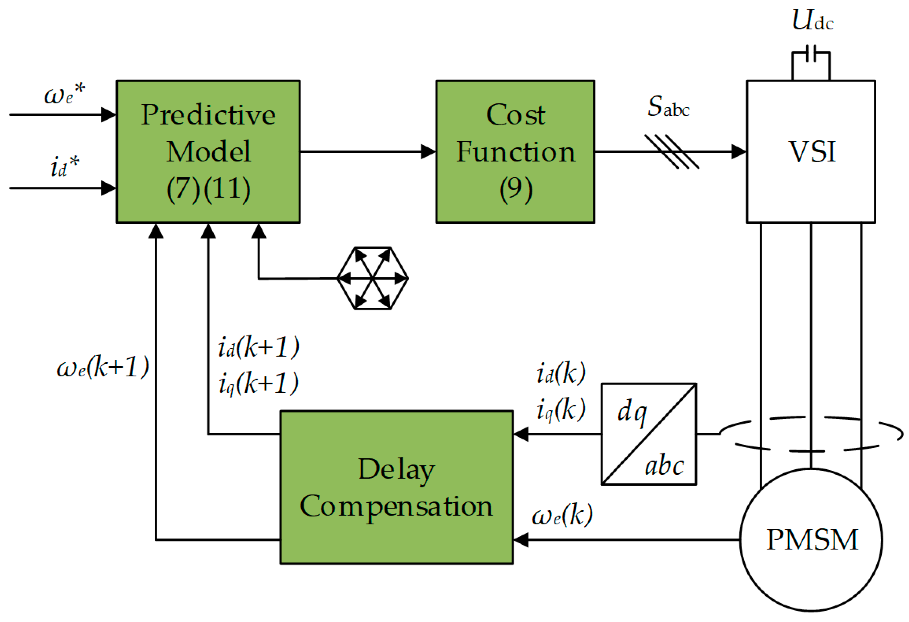
Figure 1. The basic structure of the proposed FCS-MPDSC (* represents the reference value).
Energies 16 05128 g001
Figure 2. Influence of voltage errors on optimal voltage vector selection.
Energies 16 05128 g002
Figure 3. Influence of voltage errors on optimal voltage vector selection: (a) specific switching signal situation; (b) direction of phase current during Tdead; and (c) the equivalent voltage vectors for various combinations of phase currents.
Energies 16 05128 g003
Figure 4. The change rate of the motor current.
Energies 16 05128 g004
Figure 5. The flowchart of bus voltage identification based on RLS.
Energies 16 05128 g005
Figure 6. The basic structure of the proposed FCS-MPDSC based on voltage error compensation ( * represents the reference value).
Energies 16 05128 g006
Figure 7. Experimental platform.
Energies 16 05128 g007
Figure 8. Inverter nonlinearity under FCS-MPDSC without VC: (a) mechanical velocity; (b) dq-axis currents; (c) phase currents; and (d) harmonic spectrum of phase current.
Energies 16 05128 g008
Figure 9. Inverter nonlinearity under FCS-MPDSC with CDC: (a) mechanical velocity; (b) dq-axis currents; (c) phase currents; and (d) harmonic spectrum of phase current.
Energies 16 05128 g009
Figure 10. Inverter nonlinearity under proposed FCS-MPDSC: (a) mechanical velocity; (b) dq-axis currents; (c) phase currents; and (d) harmonic spectrum of phase current.
Energies 16 05128 g010
Figure 11. Bus voltage error under FCS-MPDSC without VC: (a) mechanical velocity; (b) dq-axis currents; (c) phase currents; and (d) harmonic spectrum of phase current.
Energies 16 05128 g011aEnergies 16 05128 g011b
Figure 12. Bus voltage error under FCS-MPDSC with CDC: (a) mechanical velocity; (b) dq-axis currents; (c) phase currents; and (d) harmonic spectrum of phase current.
Energies 16 05128 g012
Figure 13. Bus voltage error under proposed FCS-MPDSC: (a) mechanical velocity; (b) dq-axis currents; (c) phase currents; and (d) harmonic spectrum of phase current.
Energies 16 05128 g013
Figure 14. Parameter errors under FCS-MPDSC without VC: (a) mechanical velocity; (b) dq-axis currents; (c) phase currents; and (d) harmonic spectrum of phase current.
Energies 16 05128 g014
Figure 15. Parameter errors under FCS-MPDSC with CDC: (a) mechanical velocity; (b) dq-axis currents; (c) phase currents; and (d) harmonic spectrum of phase current.
Energies 16 05128 g015aEnergies 16 05128 g015b
Figure 16. Parameter errors under the proposed FCS-MPDSC: (a) mechanical velocity; (b) dq-axis currents; (c) phase currents; (d) harmonic spectrum of phase current; and (e) bus voltage observation.
Energies 16 05128 g016
Table 1. The errors of voltage vectors.
Voltage VectorVoltage Value
Vector 1 [ 0 0 ]
Vector 2 [ 2 Δ U d c / 3 0 ]
Vector 3 [ Δ U dc / 3 Δ U dc / 3 ]
Vector 4 [ Δ U dc / 3 Δ U dc / 3 ]
Vector 5 [ 2 Δ U d c / 3 0 ]
Vector 6 [ Δ U dc / 3 Δ U dc / 3 ]
Vector 7 [ Δ U dc / 3 Δ U dc / 3 ]
Vector 8 [ 0 0 ]
Table 2. Parameters of PMSM.
ParametersValues
p4
Rs0.36 Ω
L0.2 mH
ψf0.0064 Wb
Udc24 V
Table 3. Experimental results using different strategies.
FCS-MPDSC
without VC
FCS-MPDSC
with CDC
Proposed
FCS-MPDSC
Speed ErrorTHD of Phase CurrentSpeed ErrorTHD of Phase CurrentSpeed ErrorTHD of Phase Current
Inverter Nonlinearity10 r/min23.2%010.1%011.6%
Bus Voltage Error40 r/min49.6%011.9%013.9%
Parameter Errors70 r/min65.9%014.1%30 r/min27.1%
Table 4. Experimental results using different strategies.
FCS-MPDSC
without VC
FCS-MPDSC
with CDC
Proposed
FCS-MPDSC
5th7th5th7th5th7th
Inverter Nonlinearity2.9%2.7%1.0%1.3%1.4%1.7%
Bus Voltage Error7.6%6.0%1.2%1.6%1.5%1.9%
Parameter Errors10.1%8.3%1.7%2.2%3.4%3.2%
Disclaimer/Publisher’s Note: The statements, opinions and data contained in all publications are solely those of the individual author(s) and contributor(s) and not of MDPI and/or the editor(s). MDPI and/or the editor(s) disclaim responsibility for any injury to people or property resulting from any ideas, methods, instructions or products referred to in the content.