1. Introduction
In recent years, PMSMs have been widely applied in industry, such as in electric vehicles [
1,
2,
3], ships [
4,
5], railway traction [
6,
7], and electric aircraft [
8,
9], due to their merits of high efficiency, high power/weight ratio, and simple structure. At the same time, model predictive control (MPC) has gained a higher profile with the development of microprocessors and power electronics due to its fast response and ease of including restrictions [
10,
11]. In this context, the literature on the application of MPC in the three-phase PMSM has been reviewed [
12,
13]. However, there are still many concerns about MPC applied in PMSMs.
In addition, multiphase PM machines, especially dual three-phase (DTP) PMSMs, are gaining increasing attention in high power and safety applications [
14,
15,
16,
17]. Compared to three-phase machines, DTP PMSMs offer improved fault tolerance and greater torque density [
18]. The extension of conventional MPC to DTP PMSMs faces two main problems. The first is the increase in computational burden [
19,
20] and the second is the existence of harmonic components in the
subspace [
21,
22,
23].
To reduce the computational burden, in [
24], only the largest voltage vectors in the DTP PMSM are chosen. However, this will cause undesirable harmonic components and worsen the performance of the total system. To this end, in [
25] a simplified predictive torque control strategy for dual three-phase motors is proposed, considering only the 36 voltage vectors in the outer three layers. However, although this method improves the control performance, the computational burden is not reduced. In [
26], a two-step MPC is proposed to reduce the switching frequency and computational burden. In this case, only six voltage vectors are used as candidate voltage vectors, effectively reducing the computational burden. Nevertheless, these methods cannot reject the influence of harmonic components in the xy subspace as only one set of voltage vectors is considered.
In [
27], the concept of a virtual voltage vector is proposed. A large basic vector and a medium-amplitude basic voltage vector are used to synthesize a virtual voltage vector. Then, a set of 12 virtual voltage vectors can be obtained to control the torque in the αβ plane and suppress the harmonic current in the xy plane at the same time. In [
28], direct torque control is implemented through virtual voltage vectors for a dual three-phase PMSM. However, these methods only output virtual voltage vectors with fixed amplitudes. The angle of the virtual voltage vector can change arbitrarily, but the amplitude is fixed. This causes a large amount of torque ripple and current ripple. To this end, in [
29], a set of 12 virtual voltage vectors is first determined. Then, in 12 sectors, two adjacent virtual voltage vectors are used to synthesize a vector. In this case, the amplitude of the virtual voltage vector can be arbitrarily changed to track the given reference voltage vector. However, this method will decrease the voltage utilization and increase the switching frequency. Moreover, there are still undesirable ripples of torque and flux, which result from the sparse voltage vectors in the αβ subspace.
To our knowledge, the existing FCS-MPC research applied in a six-phase PMSM cannot offer more precise and lower harmonic voltage vectors. Moreover, with the increasing voltage vector numbers, the cost function-based FCS-MPC could not deal with the increasing computational burden. Last but not least, those existing research works have not discussed the regulation of fixed switching frequency.
To extend the application of FCS-MPC, improved model predictive current control (MPCC) with discrete VVs (DVVs) is proposed in this paper. Discrete voltage vectors with varying angles and amplitudes are synthesized and incorporated into the control set to enhance system performance, enabling simultaneous control of both amplitude and angle. Moreover, all these discrete VVs will not cause the harmonic components in the subspace. Furthermore, all these DVVs, except the zero and largest amplitude vectors, have the same switching frequency in one control cycle. The duty cycle for these DVVs is specified in a switching table according to their amplitude and angle.
Then, a two-step selection method is investigated to release the contradiction based on the computational burden and the count of voltage vectors. The concept of DBCC is introduced to obtain the reference voltage vectors at first. Then, the duty cycle is selected from the switching table due to the index of DVVs by two-step functions. Compared to FCS-MPC with a cost function, the proposed control method achieves greater stability and reduces computational burden, without being affected by the increasing number of voltage vectors.
The remainder of this paper is structured as follows.
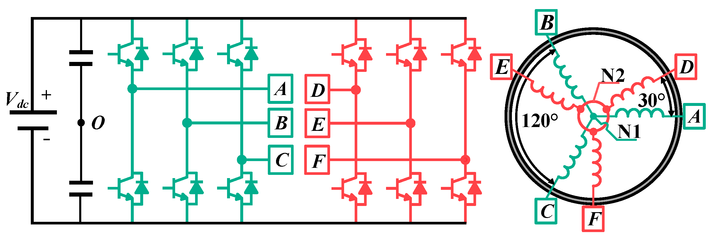
Section 2 briefly introduces the structure of a six-phase PMSM and MPCC. In
Section 3, the switching pulse generation method using VVs with a duty cycle, along with the proposed control scheme structure, is presented.
Section 4 offers both simulation and experimental results. Finally, the conclusion and potential future work are discussed in
Section 5.
3. Improved Model Predictive Current Control
This section discusses an enhanced MPCC that incorporates discrete VVs. Initially, the DVV with a duty cycle is introduced. Following that, a two-step selection method, inspired by the DBCC concept, is presented to alleviate computational complexity.
3.1. VV with a Duty Cycle
The concept of VV is to synthesize multiple vectors in one duty cycle to achieve the desired voltage vector. In a six-phase PMSM drive system, two voltage vectors, which have the same direction in the fundamental subspace and opposite directions in the xy subspace, can be synthesized within a single duty cycle to achieve more efficient control. Then, the voltage in the xy subspace can be treated as zero, which will highly suppress the influence of harmonic components.
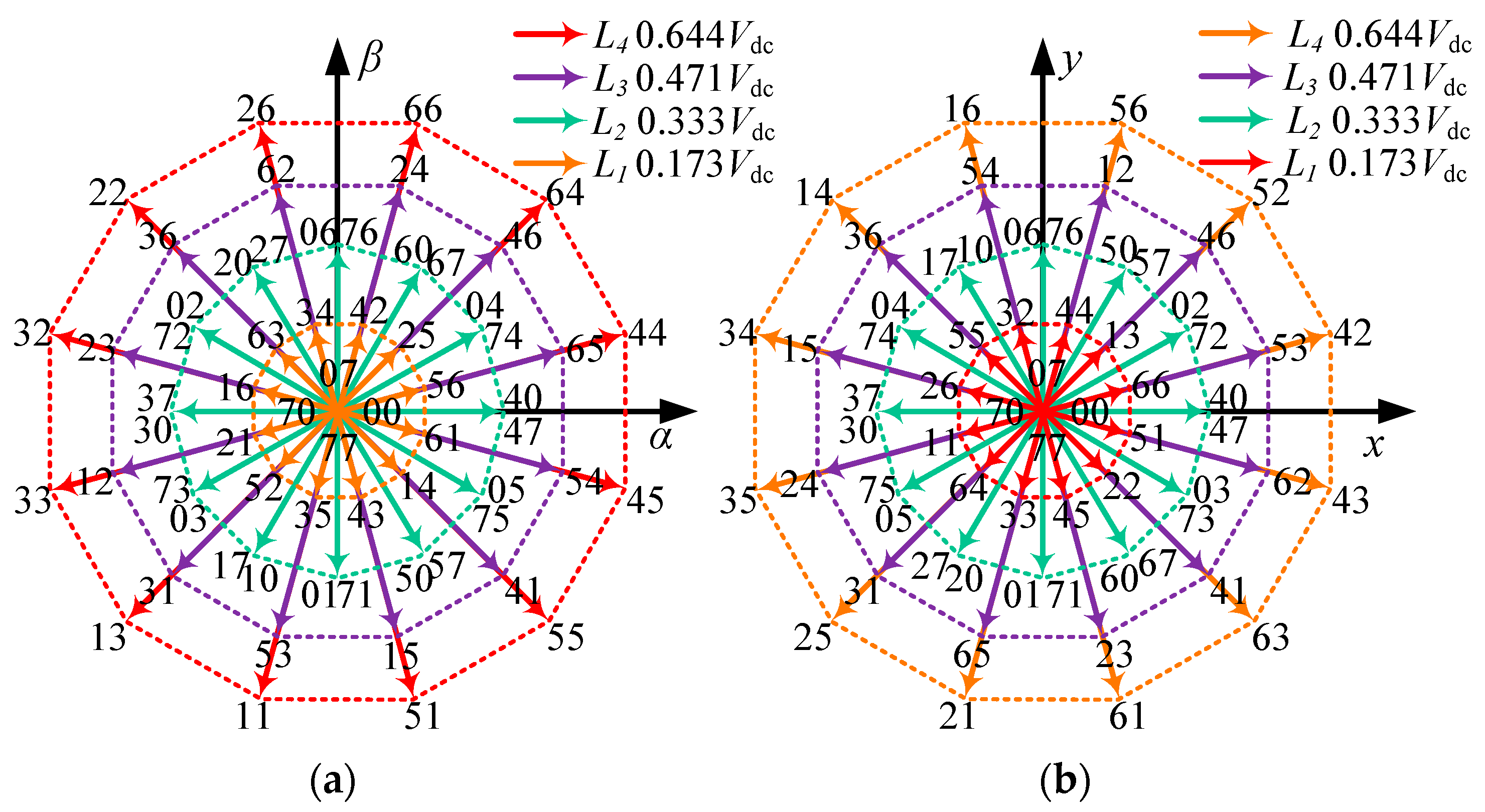
Obviously, the voltage vectors of groups L4 and L3 could be combined to achieve the largest VVs without components in the xy subspace. The proportion of these two groups can be calculated through the condition that voltage vectors in the xy subspace are zero. In this case, the duration time of each voltage vector group should be
t1 = 0.73 Tm and
t2 = 0.27 Tm. The basic form of VVs can be represented as follows:
The amplitude of the fundamental voltage vectors is 0.597 Udc, which is 7% lower than the voltage vectors in group L4.
Moreover, under the rated rotation speed and load torque situation, the application of these VVs with 0.597 Udc amplitude could fulfill the requirements of the system without too much adjustment of the zero-voltage vector, which could avoid additional ripples. In the real world, application under different speed references would introduce additional ripples in the torque and phase currents. The mechanism is the difference between the various required amplitude voltage vectors and the fixed amplitude of voltage vectors.
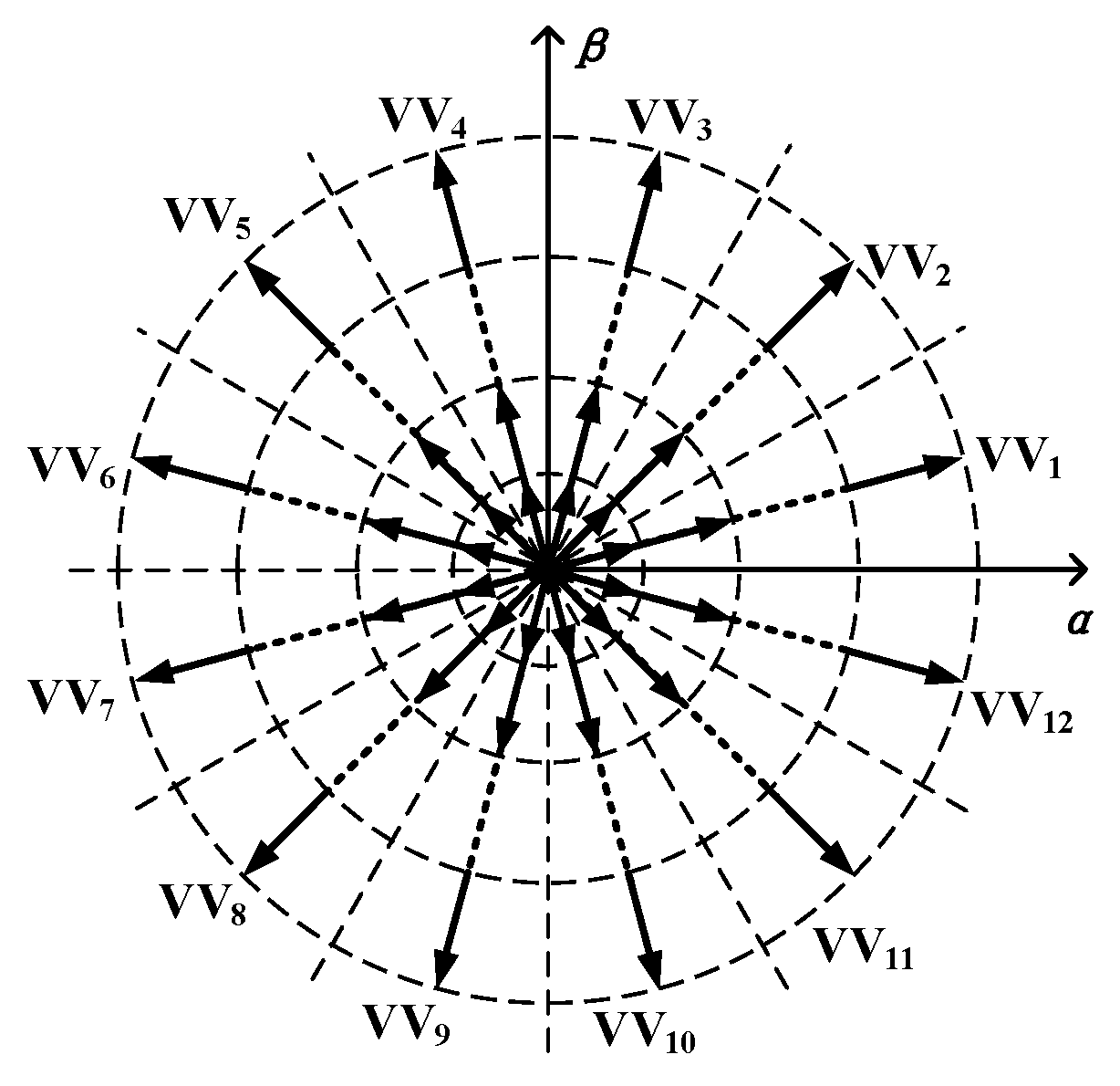
To reduce the influence of these problems, the DVV is introduced to deal with such problems. The zero-voltage vector is injected in traditional VVs to obtain the new one with different amplitudes. The distribution of DVVs in the αβ subspace is shown in
Figure 4.
Compared to conventional VVs, the proposed DVV achieves a more accurate voltage vector. While considering the generation of a standard PWM, some modifications should be introduced.
These basic VVs could be divided into two groups, namely S1 (VV1, VV3… VV11) and S2 (VV2, VV4… VV12). The VVs in group S1 could be constructed to be standard symmetrical PWMs because of the uniform arrangement of the switching state, which is shown in
Figure 5a. Standard symmetrical PWMs cannot be obtained directly in VVs in group S2 because of the conflict in the duty cycle, as depicted in
Figure 5b.
The voltage vectors in group L2 are applied to construct the standard symmetrical PWM for VVs in group S2. For instance, VV2 includes two vectors, vector 46 and vector 64. Vector 64, which is a member of group L4, can be replaced by two adjacent vectors in group L2, vector 04 and vector 67. Then, the standard symmetrical PWM of group S2 could be established by vectors in groups L3 and L2, as shown in
Figure 5c.
Finally, to adjust the amplitude of VVs, an additional duty cycle is applied to separate these basic VVs in equal amplitude. The zero vector is injected in VV1 to VV12 according to the required amplitude. Define the uniform expression of voltage vectors in the αβ subspace as:
where
i is the index of the amplitude,
j is the index of the voltage vector angle, and
A is the standard amplitude of basic VVs, which equals 0.597 Udc. In this case, the sector between VV VVi and the zero vector is divided into
N parts. The PWM generation of the proposed DVV is shown in
Figure 5d.
3.2. Proposed Two-Step Selection Method
Discrete VVs will introduce more computational burden into the conventional MPCC structure because of the increasing number of possible choices. In order to resolve this problem, a two-step selection method could be constructed.
According to the concept of DBCC, the reference voltage would force the currents to match the reference currents given by the outer speed controller in each controlling period. Using the predictive model (3), the deadbeat control scheme can be formulated through the following constraints:
where
iqref and
idref are the reference currents given by the speed controller.
Then, the reference voltage is shown in (9).
where
ed,
eq represent values related to the back EMF. From the above equation, the reference voltage vector can be obtained. This reference voltage vector is capable of driving the current state to match the reference one in the next period. Consequently, the magnitude of the reference voltage may surpass the DC bus voltage, especially during the acceleration phase.
Moreover, the system states in this instant could be predicted according to the predictive model [
25], as shown in Equation (10).
Then, the inverse park transformation, which could transform the reference voltage in the dq subspace to the αβ subspace, can be expressed as:
In this case, there are two characteristics to determine the reference voltage, which can be expressed as:
where
Aref is the amplitude of the reference voltage and
θref is the angle of the reference voltage.
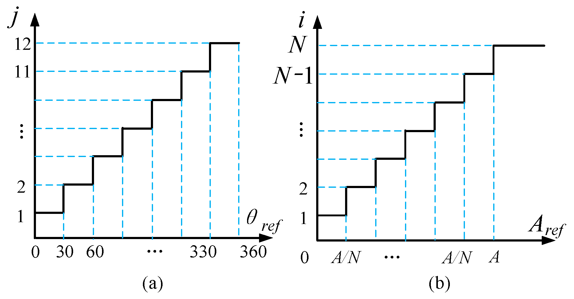
According to the angle of reference, the index number j could be determined according to the step function shown in
Figure 6a.
In general, a smaller amplitude section
N would make the distribution of voltage vectors sparse, which would cause additional ripples. While considering the influence of an overly large amplitude section
N, system noises should be considered. Due to the high-frequency disturbances introduced by the current sensors, the reference voltage calculation within the αβ subspace can be expressed as follows:
where
σα,
σβ is the disturbance caused by current sensor. Obviously, the voltage in the αβ subspace should overcome the back electromotive force (EMF) and produce torque at the same time. In practical terms, the proportion of back EMF is much larger than the torque production section, especially in high-speed regions. Then, the amplitude of the reference voltage under a steady state could be expressed as:
It needs to be mentioned that compared with the back EMF components, the high-frequency disturbance has a small value. Then, its second-order disturbance components could be eliminated. Then, Equation (14) could be simplified as:
where
iref is the current amplitude given by the PI controller. Then, the disturbance caused by the current sensors in the amplitude of voltage vectors has a similar distribution to the original high-frequency disturbance.
The duty cycle of the DVV could be selected, according to the similar step function in
Figure 6b. By increasing amplitude section
N, the performance of IMPCC would be better. However, considering the high-frequency distribution in the reference amplitude, the amplitude section
N should define a minimum interval that is larger than the disturbance, as shown in Equation (16):
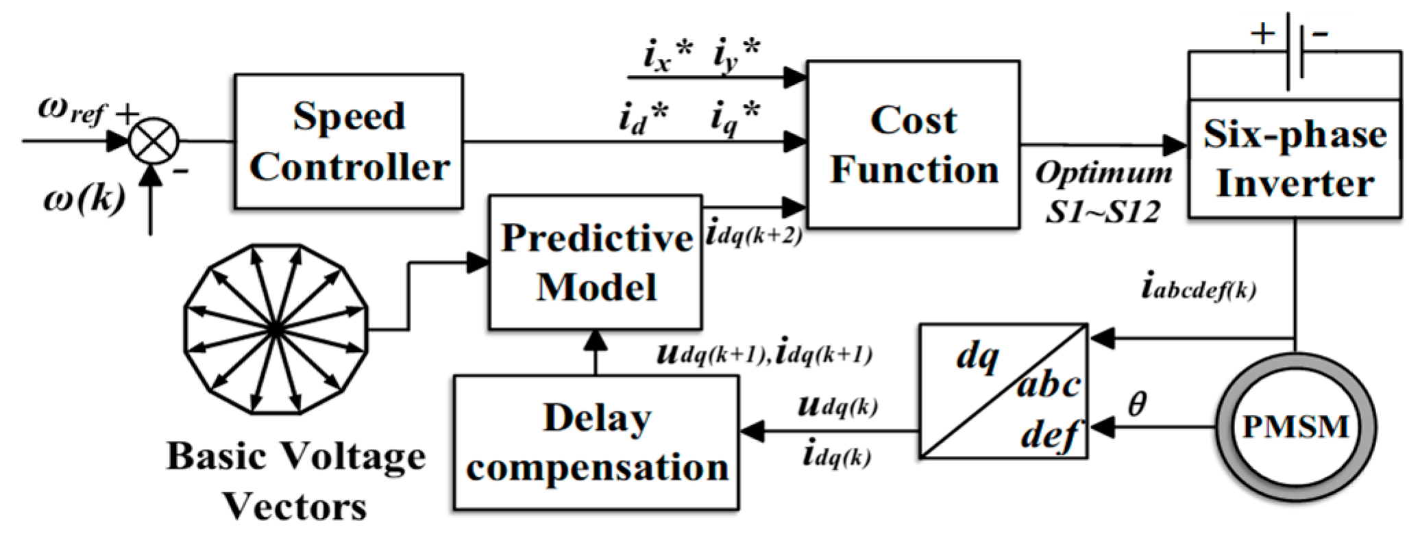
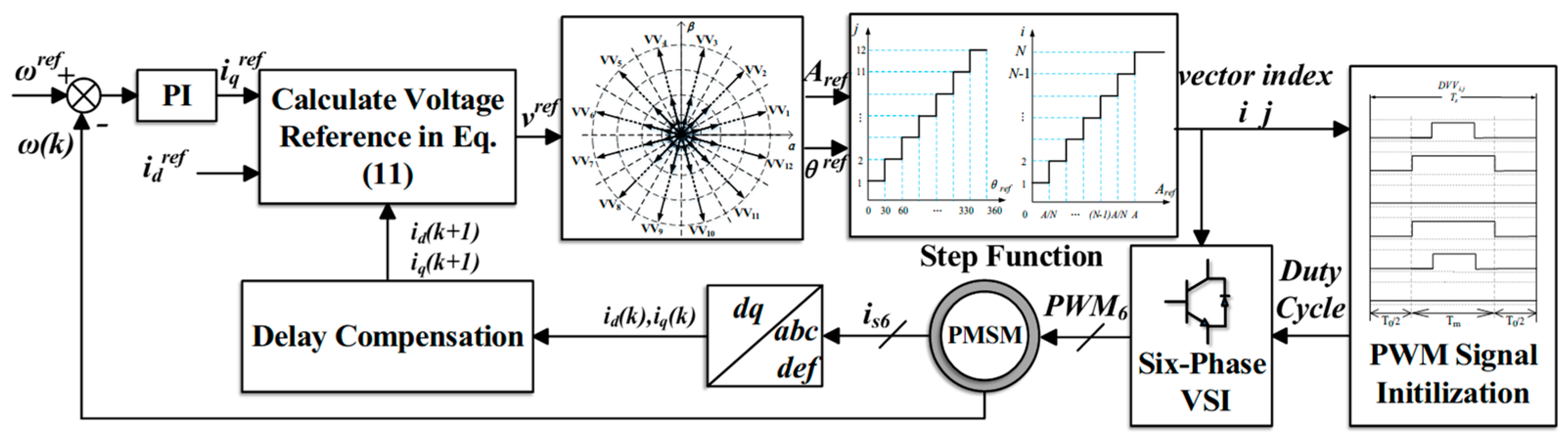
According to these two-step functions, the index of selected VVs could be easily identified. Then, the duty cycle could be determined with the initialization of the DVV. The proposed MPCC with a discrete DVV is shown in
Figure 7.
The proposed MPCC with a discrete DVV can be divided into several steps. Firstly, the improved VVs are initialized. The duty cycle is set according to the number of amplitude sections N. Secondly, the reference voltage vector is determined within the reference current and the system states. To address the effects of large control intervals, delay compensation is applied to predict the current system states. Then, the cost function in the conventional MPCC is replaced by two-step functions. The index of improved VVs could be obtained through the output of the step function. It needs to be mentioned that these two-step functions just select the index that is closest to the reference voltage vector. Actually, these two-step functions could be treated as two cost functions to obtain the minimum straight distance of the amplitude and angle. Finally, the duty cycle is determined based on the table provided during the initialization of the DVV.
In comparison to traditional VVs, the IMPCC could provide more precise voltage vectors, utilizing VVs of varying amplitudes. Additionally, it reduces the computational load by replacing the iterative optimization process with two-step functions.
4. Discussion
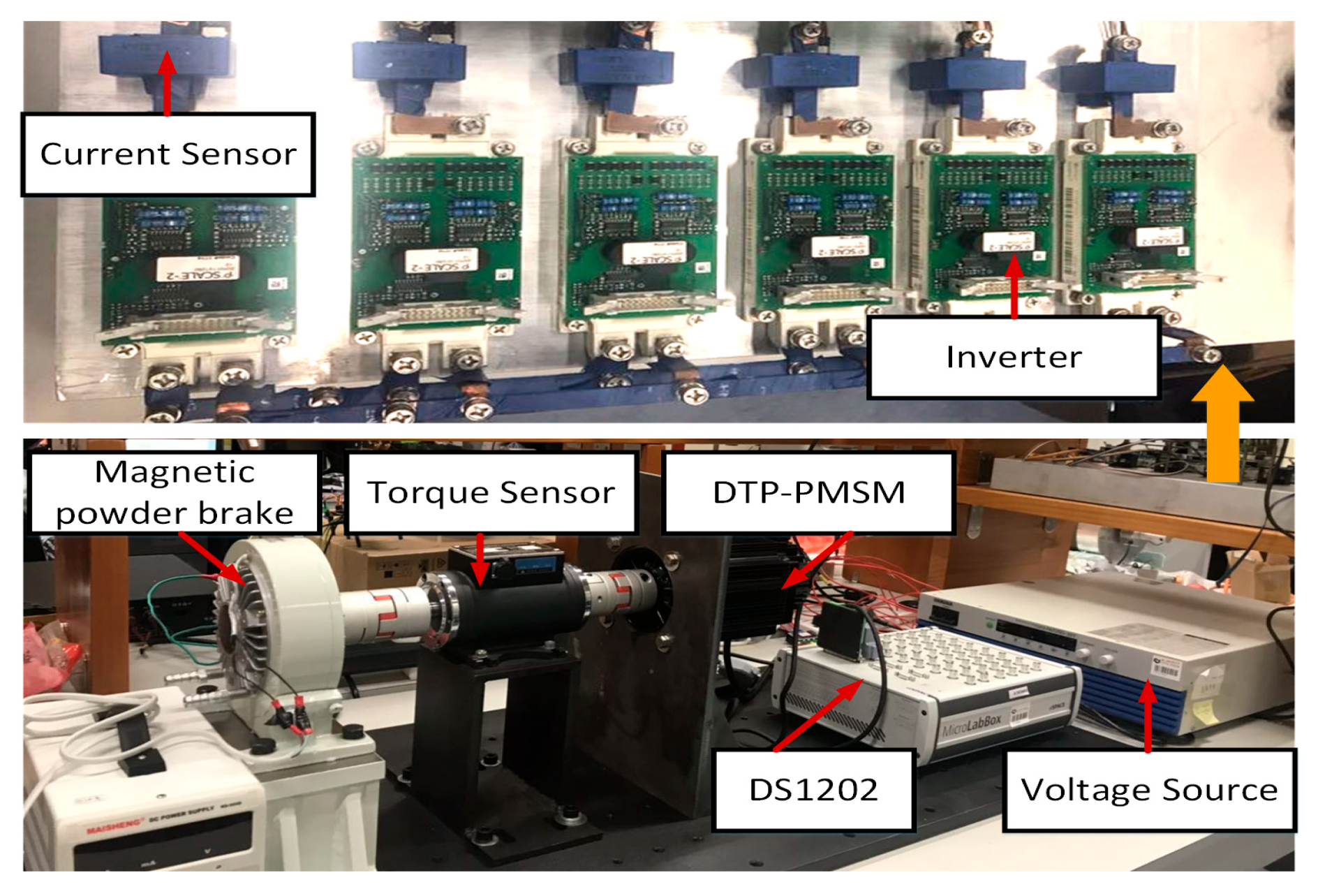
To further highlight the advantages of the control scheme in this paper, an experiment test bench is established as shown in
Figure 8. This test bench consists of a DS1202 controller, a six-phase, two-level VSI that powers the PMSM, current sensors, voltage sensors, and torque and speed sensors. The parameters of the PMSM are listed in
Table 1.
4.1. Steady-State Performance
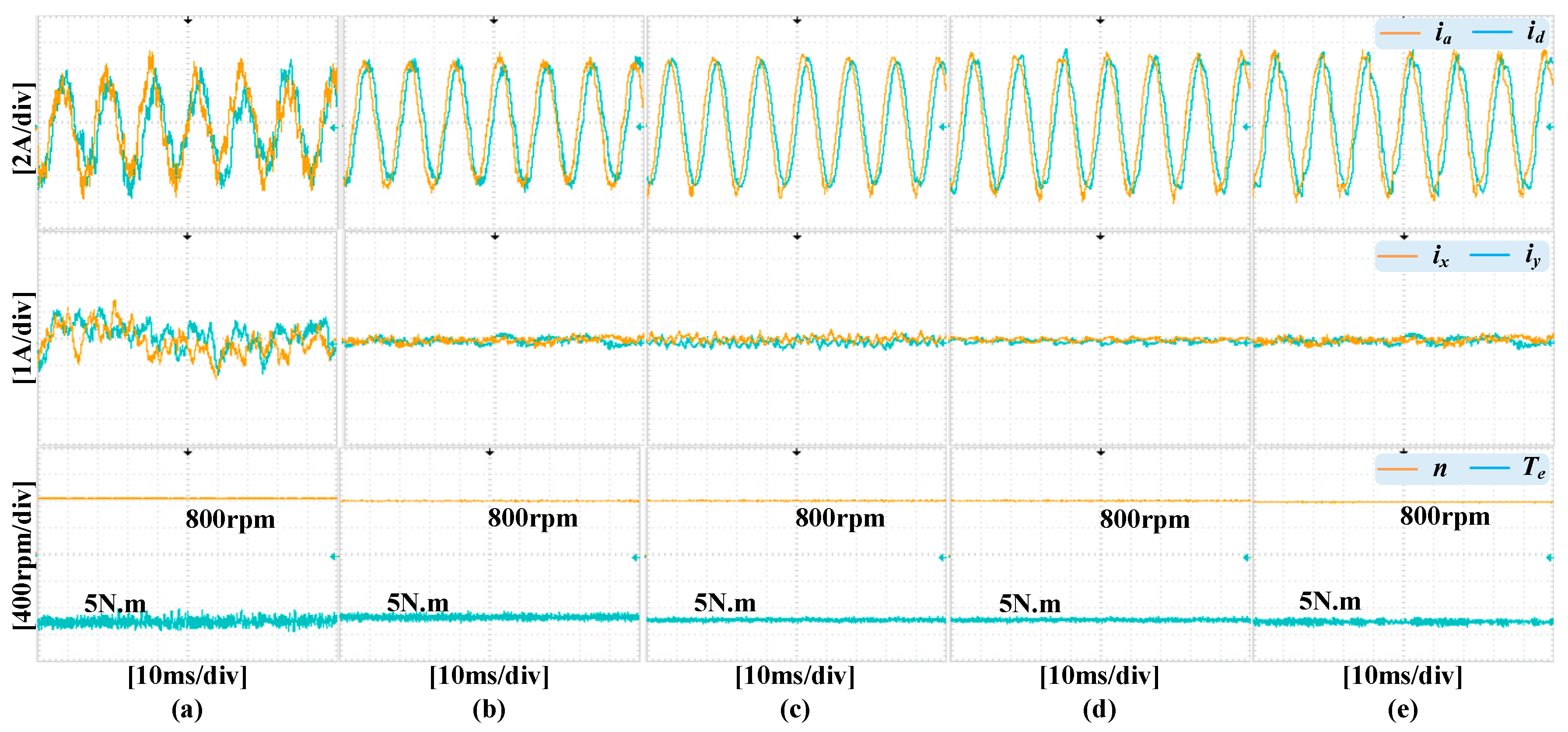
Firstly, steady-state performance under a rated load and a reference speed of 800 r/min is tested. Conventional MPCC, DBCC, MPCC with VV, IMPCC with
N = 10 under 10 kHz and 8 kHz, and IMPCC with
N = 4 are compared. As illustrated in
Figure 9, the waveforms displayed from top to bottom correspond to the stator phase currents, harmonic currents, motor speed, and electromagnetic torque.
The distinction between the traditional MPCC and other control schemes in the xy subspace primarily lies in the use of VVs. For the traditional MPCC, in one cycle, one output voltage vector leads to a large amount of harmonic current and torque ripple. As can be seen from
Figure 9, the conventional MPCC causes a ±1 A harmonic current, and the THD of the current is 20.32%, as shown in
Figure 10. This is mainly because there is a large error between the output voltage vector and the desired voltage vector. These errors lead to torque ripple and current harmonics. By applying VVs, these errors can be effectively reduced. Consequently, the voltage components in the xy subspace can be zero, resulting in sinusoidal phase currents. This means that an MPCC with virtual vectors can suppress harmonic currents and torque ripple. As a result, the current THD of the MPCC with virtual vectors is 8.56%, which is 57.8% lower than that of the traditional MPCC. The IMPCC proposed in this paper can achieve different control performances by setting
N. When
N is set to a higher value, more sectors can be obtained, leading to smaller errors between the desired vector and the output vector. Conversely, when N is relatively smaller, the error between the desired vector and the output vector is larger, but the computational effort is reduced. For example, when N is 10, the THD is 6.33%, which is 26% lower than the MPCC with VVs. When N is 4, the THD reaches 8.78%. For comparison, the IMPCC proposed in this paper is more flexible and has a better harmonic suppression effect.
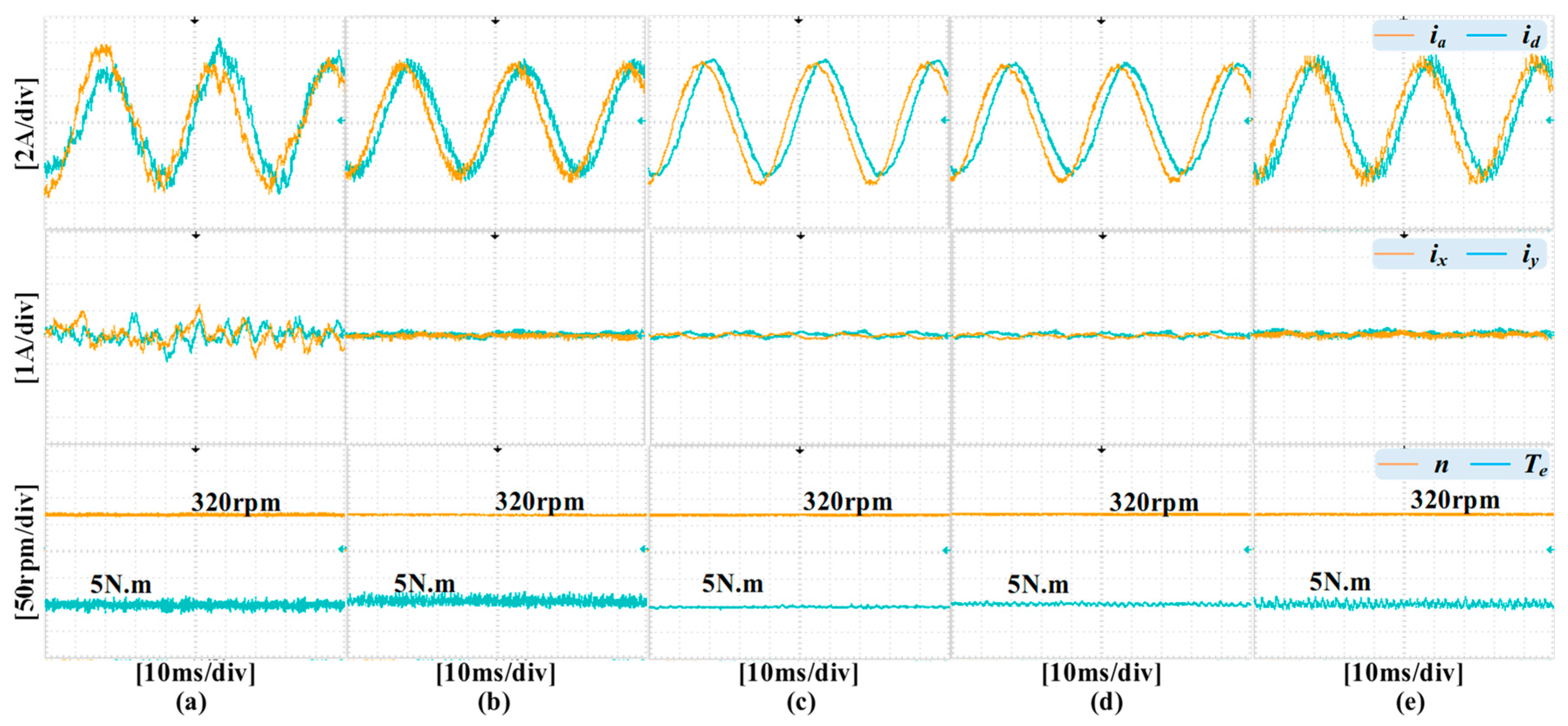
Furthermore, the performance difference becomes more noticeable with the decrease in operating speed.
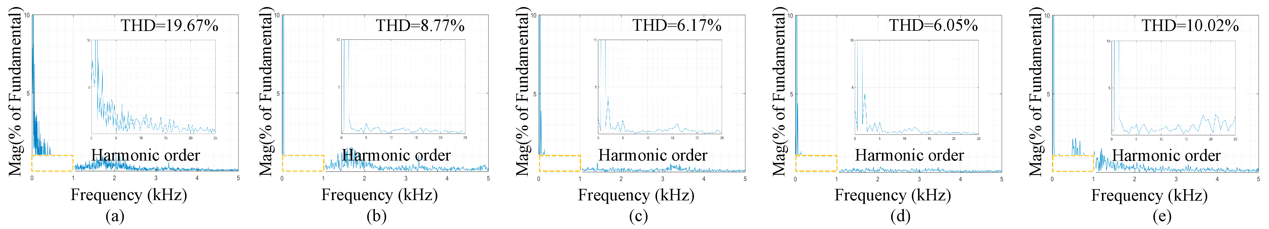
Figure 11 illustrates the steady-state performances of different control methods under a rated load and speed (320 r/min). When the motor operates at low speeds, a lower voltage vector amplitude is required. However, for the traditional MPCC, only one voltage vector with a constant amplitude is output in one cycle. This leads to a significant error between the desired voltage vector and the output vector, resulting in a harmonic current ripple of ±1 A. This method also introduces large torque and current ripples, with the current THD reaching 19.67%, as shown in
Figure 12.
For an MPCC with virtual vectors, the use of virtual voltage vectors can effectively suppress harmonic currents. Compared with the traditional MPCC, its THD is 8.56%, which is 56.4% lower than that of the traditional MPCC. For the IMPCC proposed in this paper, by adjusting the value of N, zero-voltage vectors can be inserted to reduce the amplitude of the output vector, thereby minimizing the error between the desired vector and the output vector. Consequently, its torque ripple and current ripple are reduced. When N is set to 10, the THD is 6.33%, which is 26% lower than that of the MPCC with virtual vectors. Moreover, it is worth noting that as N increases, better harmonic current suppression can be achieved.
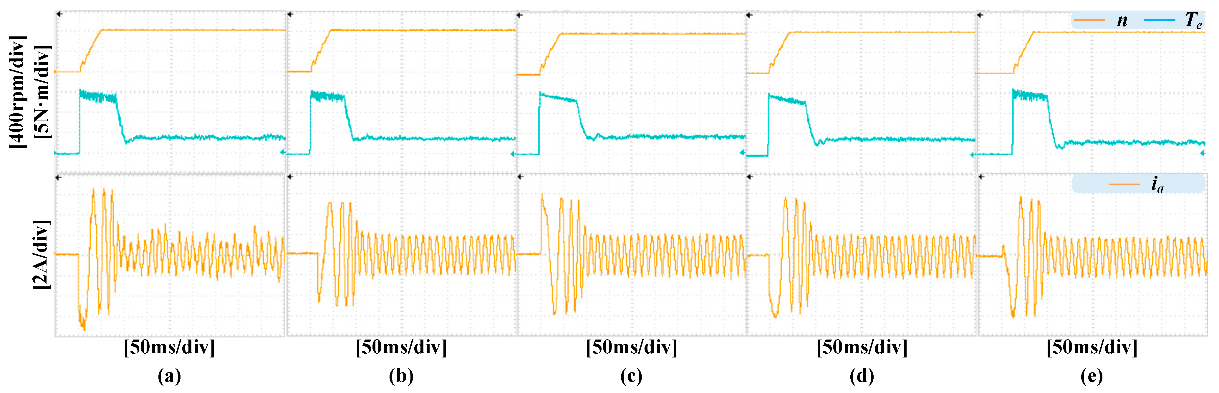
4.2. Acceleration Test
Secondly, the acceleration responses without load variation of these schemes are tested. The motor accelerates from standstill to 800 r/min under a 3 N·m load. All control schemes are evaluated using the same PI parameters.
Figure 13 illustrates the speed, torque, and phase A current responses during the acceleration phase. It can be seen that all the control schemes exhibit similar transient behaviors. All control schemes can accelerate the speed from 0 r/min to 800 r/min within 50 ms. Moreover, the speed responses are very smooth, with no observed overshoot, and the jitter in the speed curve is slight.
However, when the system enters a steady state, the current ripple of the traditional MPCC is very significant, with a ripple of ±2.5 A, causing the current waveform to become distorted. Additionally, the torque ripple is also considerable. With the introduction of virtual voltage vectors, the control performance improves. For the MPCC with virtual voltage vectors and IMPCC, both demonstrate similar current waveforms with a current ripple of ±2 A, which is 20% lower than that of the traditional MPCC, approaching a sine wave. Additionally, the torque ripple for both control strategies is relatively small.
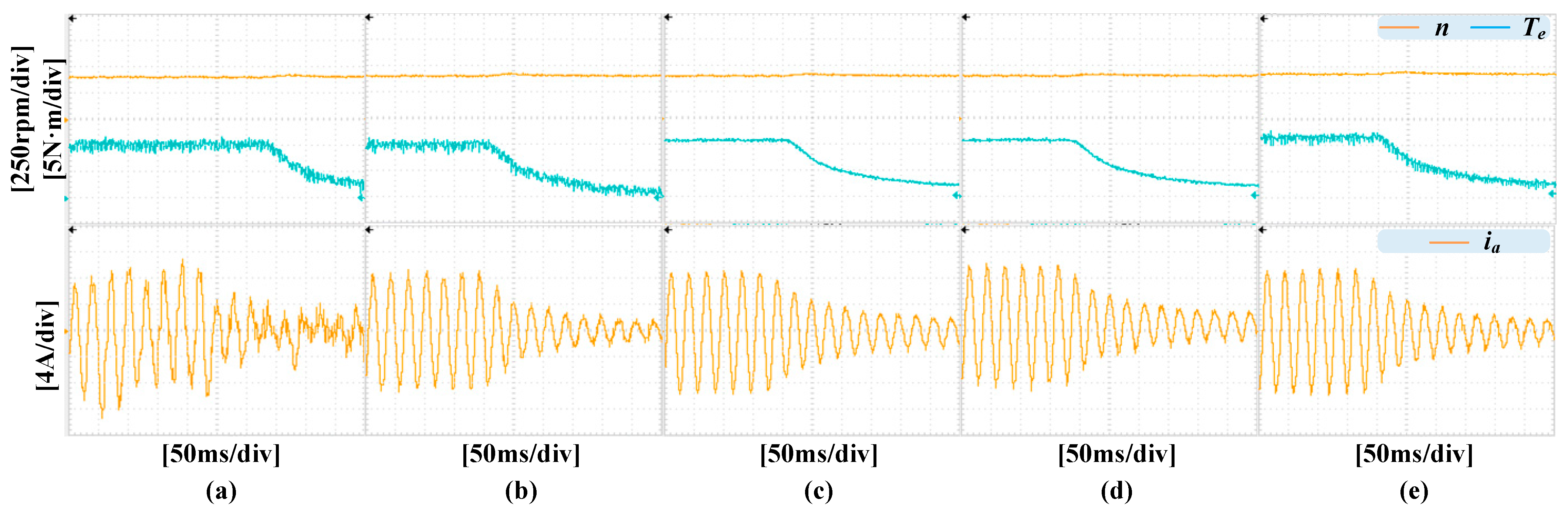
4.3. Dynamic Performance with Load Change
Thirdly, a dynamic test with load variation is performed to evaluate the performance of these control schemes. The reference speed is set to 400 r/min, while the load is adjusted from the rated value to zero.
Figure 14 shows the transient state responses of speed, load, and phase current A of all these control schemes.
All these control schemes can track the load change smoothly and quickly without any speed change within 250 ms. Moreover, when the torque decreases, the speed waveforms show a slight increase. From
Figure 14, it can be seen that the traditional MPCC exhibits a higher THD in both steady-state and dynamic conditions. When the motor operates under no-load conditions, the traditional MPCC causes significant torque ripple, with a torque ripple of ±1 N·m. The MPCC with virtual vectors generates a smaller torque ripple, approximately ±0.8 N·m, which is 20% lower than the traditional MPCC. The IMPCC proposed in this paper produces a torque ripple of ±0.2 N·m, which is 75% lower than the MPCC with virtual vectors. When N is set to 10, the phase current is closer to a sine wave. It can also be observed that when N decreases, the error between the desired vector and the output vector increases, and the torque ripple and current ripple also increase.
This section provides a comprehensive demonstration of the advantages of the proposed control scheme with DVVs, which outperforms both the conventional MPCC and the MPCC with VVs. The proposed scheme effectively suppresses current harmonics and torque ripples. Additionally, the predictive model has been redesigned to obtain the reference voltage vectors. In the conventional MPCC, the cost function is substituted by a step function for addressing the indexing of the reference voltage vectors. Through initializing the PWM generation and voltage vector indexing, the computational burden of the IMPCC is also mitigated. To evaluate the real-time performance of the IMPCC,
Table 2 presents a comparison of the computational burden between the MPCC with virtual vector and the proposed one. The MPCC with virtual vectors takes 49.8 μs to execute the control scheme, while the IMPCC proposed in this paper takes 47.4 μs, which is 4.8% faster than the MPCC. Additionally, the IMPCC simultaneously produces better control performances with respect to harmonic current suppression and torque ripple.
5. Conclusions
In general, the contradiction between the computation burden and increasing voltage vector numbers is the main problem of MPC in multiphase motors. In addition, the harmonic components and torque production related to components in different frames would cause additional problems in the voltage selection of FCS-MPC in six-phase PMSMs. To deal with the aforementioned problems, the main contributions of this paper are summarized as follows:
(1) An IMPCC with discrete voltage vectors is proposed to reduce the harmonic components. Experimental results show that, compared with the traditional MPCC, the proposed IMPCC can effectively reduce the harmonic currents at the steady state. The THD of the current is reduced from 20.32% to 6.33%, and the torque ripple is also smaller.
(2) Although the proposed IMPCC uses more voltage vectors, it achieves better control performance. Compared with the traditional MPCC, it has similar total execution times of 49.8 μs and 47.4 μs, respectively.
(3) In this paper, twelve virtual voltage vectors are synthesized from vectors in L4 and L3, with an amplitude of 0.597 Vdc, which is 7% less than the voltage vectors in L4. This method represents a trade-off between the control performance of dual three-phase motors and DC bus utilization. This method may need to be reconsidered under high-speed conditions. Existing methods also exhibit similar problems; therefore, in future work, strategies that do not reduce bus voltage utilization and control performance will be investigated, for example, by injecting common-mode voltage or synthesizing virtual voltage vectors with higher amplitudes.


