Article

Intelligent ISSA-Based Non-Singular Terminal Sliding-Mode Control of DC–DC Boost Converter Feeding a Constant Power Load System

Faulty of Metallurgical and Energy Engineering, Kunming University of Science and Technology, Kunming 650000, China
*
Author to whom correspondence should be addressed.
Energies 2023, 16(13), 4973; https://doi.org/10.3390/en16134973
Submission received: 22 March 2023 / Revised: 2 May 2023 / Accepted: 30 May 2023 / Published: 27 June 2023
(This article belongs to the Section F3: Power Electronics)

Abstract

:
In response to the issue of system oscillations in direct current (DC) microgrid systems with constant power loads (CPL), this paper proposes a non-singular terminal sliding-mode control (NTSMC) strategy based on the improved salp swarm algorithm (ISSA). Firstly, the state-feedback exact linearization technique is employed to establish a linearized model of the converter system. Then, the NTSMC based on a composite sliding-mode surface is designed to achieve rapid convergence and effectively weaken the chattering issue in traditional sliding-mode control, ensuring a constant power supply to the load. The parameters of the proposed NTSMC are optimized using the ISSA, which introduces an intelligent NTSMC. Finally, a MATLAB/Simulink simulation model is established. The simulation results show that the ISSA-based composite sliding-mode surface NTSMC system designed for DC microgrid systems with CPL exhibits high robustness and guarantees ideal steady-state characteristics and dynamic responses when input voltage fluctuations and load disturbances occur.

1. Introduction

Influenced by the growing demand for electric energy, distributed power sources, including renewable energy generation, have been integrated into the grid [1]. Microgrids (MGs), an essential component of smart grids, are small-scale power systems that promote the effective integration of distributed generation [2]. In addition, MGs, as an effective means to improve new energy absorption capacity and a valuable supplement to large grids, are the future development trend of distributed clean energy supply systems [3]. In the future, MGs will play an essential role in intelligent distribution and innovative grid systems [4]. MGs can be divided into direct current micro-grids (DCMGs) and alternating current micro-grids (ACMGs) according to the type of access bus between the load and distributed energy in the MG [5]. In particular, unlike ACMGs, DCMGs do not have reactive power compensation and harmonic power balance problems and do not require reactive power compensation capacitors and other equipment [6]. In addition, the design of DCMGs is simple, and their cost of construction is low [7]. Therefore, studying the green and reliable power supply of DCMGs with practical significance and application value is vital.
DCMGs contain several DC–DC converters interconnected in a cascade to meet operating conditions. These converters serve as the central power processing units for renewable energy sources and the grid, coordinating the power quality and voltage amplitude requirements of the power sources and loads [8]. In the DC–DC converter cascade form, the front converter is the feeder system, and the back converter is the load system [9]. Most converters are controlled internally by closed-loop control to ensure their output of stable voltage and current [10]. When a load converter is connected to a constant-size resistor, its output power is constant and can be considered the constant power load (CPL) of the front-stage feeder system [11]. A CPL with negative impedance characteristics cascaded with a DC–DC converter reduces the reliability of the system’s power supply and even endangers the system’s stability [12]. In particular, in high-voltage DC distribution systems and DCMG systems, CPLs account for more than 75% of the total load, posing a significant challenge to the operation and control of distributed power supply systems [13].
DC–DC converter systems with CPL have high control difficulty because of fluctuations in their circuit parameters and nonlinear characteristics. Therefore, designing a reasonable stabilization control strategy to improve the nonlinear performance of DC–DC converter systems with CPL and to imbue it with good steady-state and dynamic characteristics is the key to improving the control performance of the DCMG. This control problem has become a current research hotspot [14]. Aiming to deeply analyze and study the control problem of DC–DC converters and find a better control method, more and more scholars have shifted their research focus to the control of these systems, and rich research has been carried out for DC–DC converters. DC–DC converters with CPL are a nonlinear system based on traditional control methods. In order to obtain the small signal model necessary for these systems, the system is linearized around the equilibrium point. Then, control theory methods such as linear double closed-loop PID are used to design the controller [15]. However, closed-loop PID control does not guarantee optimal performance. The converter under different controller parameters and the requirement for the current loop to have sufficiently high bandwidth to suppress disturbances effectively increase the controller design and implementation difficulty. Therefore, there are better control methods than linear double closed-loop PID control for power electronic converters.
In order to cope with the adverse effects on system stability that occur when CPLs are present, significant theoretical results have been obtained for the control of nonlinear systems of DC converters with CPLs through continuous in-depth modeling analysis and control studies. They can be divided into two main categories: passive damping techniques (PDTs) and active damping techniques (ADTs). PDTs increase the damping of the system to counteract the negative impedance characteristics of the CPL by adding passive components such as resistors, capacitors, and inductors to the system [16,17]. However, this approach increases the cost and complexity of the system. Furthermore, the compensated passive components increase the power loss and make the system less efficient.
ADTs are mainly used to increase the system damping to counteract the negative impedance characteristics of the CPL by adding compensation measures to the system control loop. Commonly used ADTs include backstepping control (BC), feedback linearization control (FLC), and sliding mode control (SMC). These techniques provide a more flexible and effective solution for system damping than PDT methods. Active damping techniques achieve the damping effect on series/parallel resistors in nonlinear circuits with CPLs by adding a compensation factor to the control structure on the source or load side of the feeder. In [18], the dynamic performance of the DCMG is improved by applying the active damping technique to the bidirectional DC–DC converter in the DCMG. Compared to passive damping techniques, active damping techniques do not lead to an additional increase in the size and complexity of the circuit system.
Kanellakopoulos and Kokotovic first proposed BC to achieve the systematic design of systems with uncertain parameters [19]. The basic idea is to convert a complex nonlinear system into subsystems below the order of the system by decomposition, to design intermediate virtual quantities and Lyapunov functions for the resulting subsystems and back off to the whole system, and finally, to integrate all virtual control quantities to achieve the design of the whole control law [20]. In [21], a composite nonlinear controller combining BC and double integral SMC was proposed and used for a CPL-fed DC–DC enhancement converter. The proposed controller improved the DC bus voltage stability under large perturbations in DC distribution systems. In [22], a third-order Kalman filter estimation method for CPL was proposed. The estimated value was fed back to the connected adaptive BC controller to obtain the switching duty cycle and achieve accurate tracking of the output voltage reference to stabilize the system. In [23], a BC method was used to complete the controller design for CPL loads driven by boost converters in DCMG to achieve bus voltage stabilization in DCMG.
FLC is an essential branch of differential geometric methods. Its core idea is to counteract nonlinear features in a system by introducing nonlinear coordinate transformations and state feedback [24]. Unlike approximate linearization methods, FLC is not limited by the vicinity of the operating point. FLC is an exact method for converting nonlinear systems into linear energy systems that can be controlled linearly and for using traditional linear control theory to design controllers to achieve the desired performance index [25]. FLC does not ignore higher-order terms and can ensure that closed-loop systems have ample signal stability. However, parameter perturbations in the system often lead to its slow transient response, so it needs to be combined with other control algorithms to improve a system’s dynamic performance [26]. The objective holographic FLC can stabilize a system by bypassing the non-minimum phase system, for which the method places the pole-zero of the system at the corresponding desired position through feedback to achieve the satisfactory dynamic and static performance of the control system with CPL [27]. In [28], a method based on an LFC combined with a disturbance observer was proposed. The LFC compensates for model uncertainties and unknown loads to ensure asymptotic regulation under a composite controller. Experiments show that this controller can achieve good transient and steady-state performance in the CPL system. Similarly, to stabilize the DCMG system and determine the stabilization strategy of the nonlinear system by designing the linearized system’s feedback coefficients, the DC–DC converter’s DCMG stabilization strategy’s feasibility and effectiveness was verified by simulation results in MATLAB [29].
SMC is a nonlinear, robust control technique. SMC is robust to perturbations of the control object itself [30]. Usually, the system’s dynamic moves along the designed sliding-mode state trajectory according to the current system deviation and the dynamic changes of its state derivatives to maintain stability on the sliding-mode surface [31]. SMC has been widely used in controlling DC–DC and AC–DC power converters, especially in controlling the instability of power electronic systems caused by CPL fluctuations due to its fast response and simple implementation [32,33]. However, SMC requires constant logic transitions as a discontinuous control method. This situation inevitably leads to jitter phenomena that affect the system’s stability, thus limiting the system’s tuning time and convergence speed. Therefore, how to eliminate the jitter phenomenon has become a research hotspot for scholars in related fields [34]. In [35], for DC–DC converters with CPL, an SMC control strategy based on pulse-width modulation (PWM) was adopted to suppress the instability caused by CPL in DCMG systems in order to improve the overall MG control performance. The literature [36,37] demonstrates that, to suppress the effect of the system’s aggregate disturbance, a composite control scheme combining SMC and disturbance observer has been designed for the Buck converter, which has good anti-disturbance and transient performance when the CPL fluctuates.
A review of the DC–DC converter research reveals the following problems. In some papers, the voltage fluctuation range is extensive, so in some cases, there is no good damping effect. Most papers achieve proper damping but neglect the CPL’s nonlinearity, so the controller can easily track variations and suppress oscillations. In addition, the SMC described above was applied to the Boost DC–DC converter control problem. However, the SMC is not intelligent, and the designer must manually select the parameters of the SMC; furthermore, optimization methods were not used to optimize the tunable parameters. The authors of the present study know of no studies on using the Boost DC–DC converter controller with CPL based on the composite sliding-mode surface non-singular terminal sliding-mode control strategy technique (NTSMC) and the ISSA to solve the stabilization problem for islanded DCMGs.
This paper is organized as follows. In Section 2, the principle of exact feedback linearization is presented, as well as the required mathematical conditions. Section 3 presents the dynamical equations of the Boost DC–DC converter and the CPL. Then, in Section 4, an NTSMC is designed for the Boost DC–DC converter control. Section 5 presents the ISSA and its application to the NTSMC parameter optimization problem. A simulation study is performed in Section 6 to show the advantages of the new method. Finally, Section 7 concludes the paper.

2. Preliminaries

State-feedback linearization addresses nonlinear system characteristics by applying techniques such as coordinate transformations and nonlinear state feedback. This approach transforms the original nonlinear system into a linear, controllable system. It can be applied over a broad range rather than just near the system’s working point. The result is an effective solution that offers significant benefits for system control [38,39].

2.1. Differential Geometry Concepts

Differential geometry methods are widely used for analyzing the structure and designing controllers for nonlinear control systems. As a result, they have become an important research direction in nonlinear control. State feedback linearization requires extensive knowledge of differential geometry and differential topology. Therefore, this section provides an introduction to the relevant theoretical knowledge.
Diffeomorphism plays a crucial role in nonlinear systems, extending the concepts of linear transformations in linear systems. It enables the conversion of certain nonlinear systems into linear ones through appropriate mappings. A differential homogeneous mapping is defined as a smooth, homogeneous mapping f : X Y , where f and its inverse mapping f 1 are smooth. When a differential homogeneous mapping exists between sets X and Y , they are considered Diffeomorphic. This concept establishes a one-to-one correspondence while preserving the structural properties and smoothness of the sets. By harnessing Diffeomorphism, nonlinear systems can be transformed into linear systems, facilitating analysis and leveraging established linear systems theory. This opens up new possibilities for understanding and manipulating nonlinear dynamics in diverse scientific and engineering fields.
Definition 1.
Expanding upon the concept of Diffeomorphism, we can establish related definitions. Consider a smooth function h : X R defined on an n-dimensional differential manifold X , along with a smooth vector field f : X T p X . The Lie derivative L f h : X R captures the derivative of h along the vector field f . Mathematically, it is expressed as
L f h ( p ) = f ( h ) ( p ) = i = 1 n f i ( p ) h x i ( p ) , p X .
A vector field is defined as such that for all p X , f ( p ) T p X , where a smooth vector field refers to a vector field that has partial derivatives of any order concerning its independent variable. The definition of solving higher-order Lie derivatives is as follows:
L f k h ( x ) = L f k 1 h x f ( x )
The zero-th order Lie derivative is defined as L f 0 h ( x ) = h ( x ) .
Definition 2.
For two smooth vector fields f and g defined on the subset U of R n , the new vector field Lie product [ f , g ] is
[ f , g ] = g f f g
where g and f represent the Jacobian matrices of vector fields g and f, respectively, and the Lie product [ f , g ] is commonly written as a d f g . From its definition, it can be seen that
a d f g = [ f , g ] ( x ) = g x T f f x T g
where g x T and f x T are
g x T = g 1 x 1 g 1 x 2 g 1 x n g 2 x 1 g 2 x 2 g 2 x n g n x 1 g n x 2 g n x n , f x T = f 1 x 1 f 1 x 2 f 1 x n f 2 x 1 f 2 x 2 f 2 x n f n x 1 f n x 2 f n x n
In addition, the vector field g can also perform multiple Lie product operations on other vector fields f , yielding
a d f i g = f , a d f i 1 g , i = 1 , 2 ,
where the zero-th order Lie derivative is defined as a d f 0 g ( x ) = g ( x ) .

2.2. State-Feedback Linearization

A single-input–single-output (SISO) affine nonlinear dynamic system can be described as
x ˙ = f ( x ) + g ( x ) u y = h ( x )
The relationship between the input u and the output y of the SISO affine nonlinear dynamic system can be established by taking the derivative of the output and using the Lie derivative, as follows:
y ˙ = h ( x ) x x ˙ = h ( x ) x ( f ( x ) + g ( x ) u ) = L f h ( x ) + L g h ( x ) u
If there is L g h ( x ) = 0 near x 0 , then taking the derivative of Equation (8) results in
y ¨ = L f h ( x ) x x ˙ = L f h ( x ) x ( f ( x ) + g ( x ) u ) = L f 2 h ( x ) + L g L f h ( x ) u
Similarly, if in the vicinity of x 0 , it holds that L g L f h ( x ) = 0 , we can take successive derivatives of the system output function y ( t ) until
y ( r ) = L f r h ( x ) + L g L f r 1 h ( x ) u
According to Equation (9), if x = x 0 and L g L f r 1 h x 0 0 , then due to the fact that f ( x ) and g ( x ) are smooth vector fields and h ( x ) is a smooth function, there exists x 0 U such that for any x within the domain U , we have L g L f r 1 h ( x ) > a 0 , where a 0 R + is a positive constant.
A new input is defined as v R , and a nonlinear input transformation is introduced by Equation (11).
u = L f r h ( x ) + v L g L f r 1 h ( x )
Let us define a new input signal v ( t ) R and introduce a nonlinear input transformation so that the original output signal y and the new input signal v establish the following rth order linear differential equation:
y ( r ) ( t ) = v ( t )
At the same time, the feedback linearization order determines the input transformation’s final form and the system’s order, which is essential in the feedback linearization process. For affine nonlinear systems, if the following conditions are satisfied in the neighborhood of x 0 , D 0 : x D 0 , L g L f i 1 h ( x ) = 0 , ( 0 i < r 1 ) and L g L f r 1 h x 0 0 at x 0 , then the system has a relative degree of r at the point x 0 . The relative degree characterizes the dynamic response relationship between the input and output of the system.

2.3. Conditions for State-Feedback Exact Linearization

The condition of exact feedback linearization is the complete linearization of nonlinear systems, which must strictly meet exact linearization conditions [40,41]. The relationship between the relative order of the system and the dimensionality of the system–state space n mainly includes two cases, r < n or r = n . The necessary and sufficient condition for the SISO affine nonlinear system to realize exact feedback linearization is that there exists a neighborhood D 0 D such that the relative order r of the system is equal to the dimensionality of the system n, which requires that the following condition restrictions be met:
(1) For all x D 0 , the matrix B = g ( x ) a d f g ( x ) a d f n 1 g ( x ) has rank n.
(2) The distribution ζ = span ( g a d f g a d f n 2 g ) is involutive in the neighborhood D 0 ; that is, for any τ 1 , τ 2 D , their Lie bracket is τ 1 , τ 2 D .

3. Modeling of a DC Microgrid with CPL

3.1. Boost Modelling

A typical DCMG system structure is shown in the islanding mode in Figure 1. It comprises distributed energy sources (PV power and fuel cells), energy storage devices, and loads (including resistive and CPL loads). Typically, a distributed energy source needs to be connected to a DCMG through a converter, and the load must also be controlled through the converter. Taking the most common distributed energy source connected to the DC bus through the Boost converter as an example, the topology of a simplified DCMG cascade system with CPL is shown in Figure 2.
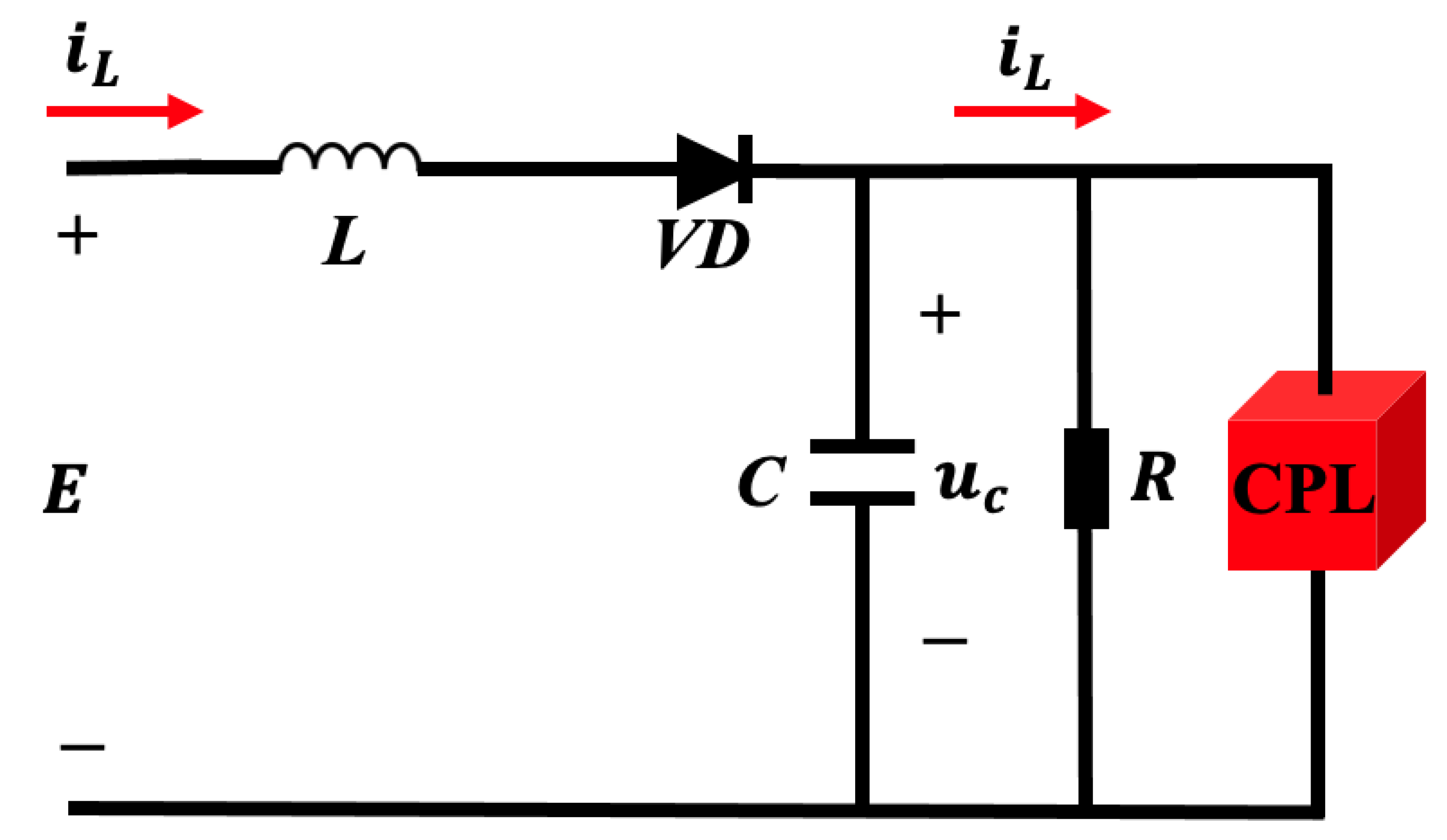
In Figure 2, the power switch S is controlled by PWM, V D is the diode, L is the inductor, i L is the inductor current, E is the input voltage, C is the filter capacitor, u C is the DC bus voltage, and R is the resistive load resistance.
The switch resistance, diode on-resistance, inductor resistance, and capacitor equivalent series resistance are assumed to be zero. The input control variable u ( 0 , 1 ) is the duty cycle function, which regulates the on and off states of the converter switch. The switching period is T s . According to the two operating states (on and off) of the switching tube S, the system is divided into the following two operating modes.
When 0 < u < u T s , the switch S turns on and V D turns off, the system is in the first mode of operation as shown in Figure 3.
According to the relationship of each circuit parameter in Figure 3, the Kirchhoff law of voltage and current yields
L d i L dt = E u C C d u C dt = i L u C R P u C
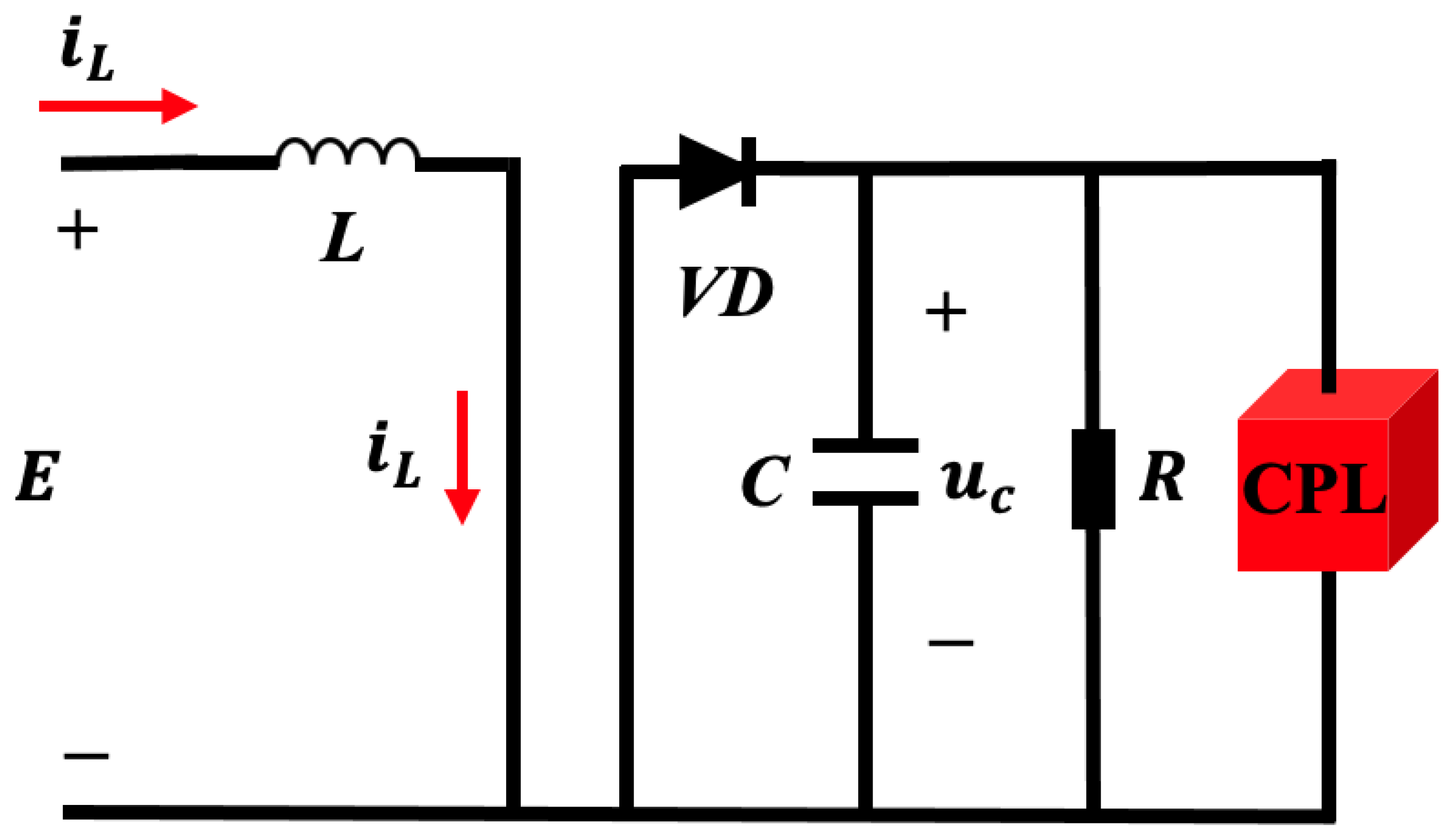
When u T s < u < T s , V D turns on, and S turns off, the system is in the second mode of operation, as shown in Figure 4.
Similarly, the relationship between the circuit parameters in Figure 4 can be deduced from Kirchhoff’s voltage and current laws:
L d i L dt = E C d u C dt = u C R P u C
According to Figure 3 and the system shown in Figure 4, the operating state of the DC–DC converter changes between modes as the switching state of the switching tubes changes. By applying Kirchhoff’s voltage and current laws, we can obtain
L d i L dt = E ( 1 u ) u C C d u C dt = ( 1 u ) i L u C R P u C

3.2. CPL Modeling

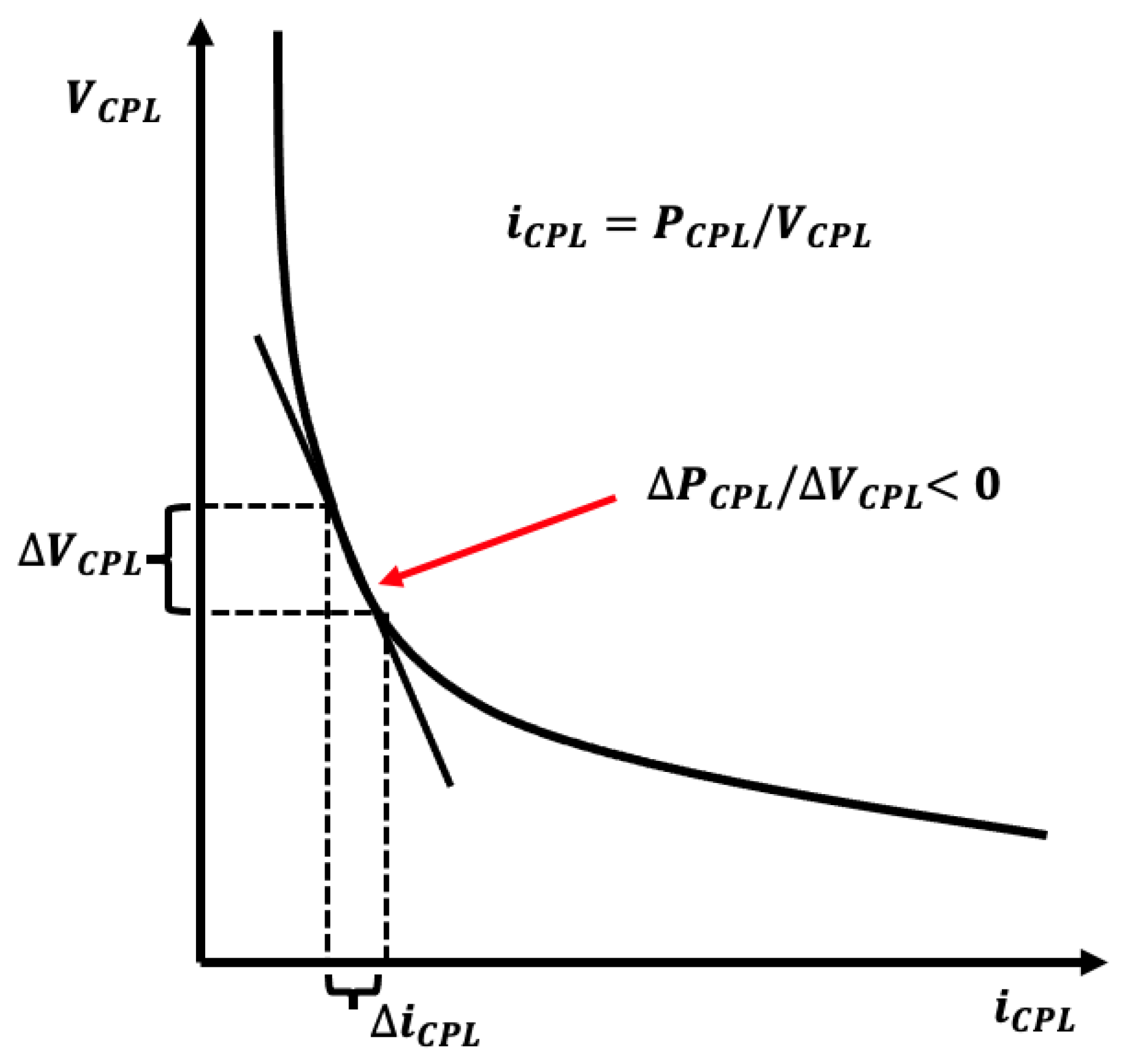
A typical CPL voltammetric curve is shown in Figure 5, where the current drawn by the CPL is inversely proportional to its voltage. When the voltage across the CPL becomes more prominent, the current value decreases accordingly; conversely, when the voltage across the CPL decreases, the current becomes larger accordingly [42]. Therefore, the load characteristics of CPL can be described as
i CPL = P CPL v CPL v CPL > ε
where P CPL is the rated power of CPL ; i CPL is the current absorbed by CPL ; v CPL is the voltage across the CPL; and ε is an arbitrarily small positive value.
The small-signal model of CPL is derived by approximating the operating point of the V-I curve of CPL with a tangent line. This approximation involves performing a first-order Taylor expansion of Equation (16) around its current operating point. The small-signal approximation for the current i cpl is then given by:
i cpl P v cpl P v cpl 2 v cpl v cpl = 2 P v cpl P v cpl 2 v cpl

4. Controller Design

4.1. Feedback Linearization

The Boost model described by Equation (15) is nonlinear, and in this paper, the state variables x 1 = i L and x 2 = u C are chosen. Then, Equation (15) can be rewritten as:
x ˙ 1 = 1 L E ( 1 u ) x 2 x ˙ 2 = 1 C ( 1 u ) x 1 x 2 R P x 2
To make the output voltage track the set reference voltage, we define the output function as
y = h ( x ) = x 2 u Cref
where u Cref is the output voltage’s reference value.
The affine nonlinear standard type describing the system can be obtained as
X ˙ = f ( X ) + g ( X ) u y = h ( X ) = x 2 u Cref
where f ( X ) = E L x 2 L x 1 C x 2 R C P C x 2 T , g ( X ) = x 2 L x 1 C T .
Then, the Lie derivative of the original output function h ( x ) = x 2 u C r e f for the nonlinear system yields
L g h ( x ) = h ( x ) x g ( x ) = x 1 C
According to the conditions that must be satisfied for the exact feedback linearization described in Section 2.3, it is clear that the output function y = h ( x ) defined by Equation (19) cannot be linearized exactly by the coordinate transformation. Therefore, it is necessary to reconstruct the output function so that the relative order of the system is equal to the system’s dimension. In order to determine the new output function y = ω ( x ) , the following partial differential equation needs to be solved:
L g L f 0 ω ( x ) = L g ω ( x ) = ω ( x ) x g ( x ) = 0
Expanding Equation (22) yields
ω ( x ) x 1 x 2 L ω ( x ) x 1 x 1 C = 0
Solving Equation (23) yields
ω ( x ) = 1 C x 1 2 + 1 L x 2 2
Combining the system output functions described by Equation (24), the nonlinear system model of the DC–DC converter with CPL can be rewritten as:
x ˙ = f ( x ) + g ( x ) u y = ω ( x ) = 1 C x 1 2 + 1 L x 2 2
To achieve the exact feedback linearization, the following Lie derivatives are calculated from the new output function:
L f ω ( x ) = ω ( x ) x f ( x ) = 2 x 1 C 2 x 2 L f ( x ) = 2 R L C E R x 1 x 2 2 R P L g L f ω ( x ) = L f ω ( x ) x g ( x ) = 2 E L C 4 x 2 R L C g ( x ) = 2 E L 2 C x 1 + 4 x 1 x 2 R L C 2 L f 2 ω ( x ) = L f ω ( x ) x f ( x ) = 2 E L C 4 x 2 R L C f ( x ) = 2 E E x 2 L 2 C + 4 x 2 R L C 2 x 2 R P x 2 x 1
Therefore, according to the calculation result of Equation (26), the following coordinate transformation can be defined:
z = z 1 z 2 = ω ( x ) L f ω ( x )
The derivatives of z 1 and z 2 in the coordinate transformation are obtained as
z ˙ 1 z ˙ 2 = z 2 L f 2 ω ( x ) + L g L f ω ( x ) u
A new control variable v is defined, whose mathematical expression is
v = L f 2 ω ( x ) + L g L f ω ( x ) u
Then, the nonlinear system described by Equation (20) can be changed into the following linear second-order system of the Brunovsky standard type:
z ˙ 1 z ˙ 2 = 0 1 0 0 z 1 z 2 + 0 1 v

4.2. Design of NTSMC

The conventional non-singular terminal sliding mode controller (NTSMC) exhibits slow convergence during the sliding mode. To address this issue and enhance system performance, this paper proposes a novel NTSMC controller based on a composite sliding mode surface. The controller is designed to improve the convergence speed and reduce tuning time of the system. It focuses on achieving satisfactory dynamic tuning capability and robust performance for the system’s reference voltage u C r e f and reference inductor current i L r e f . By incorporating the composite sliding mode surface, the controller aims to provide efficient tuning and robust control, offering improved performance and faster convergence for various applications.
According to the state space equation described by the system described by Equation (30), the error variable for its control is defined as
e 1 = z 1 z 1 ref e 2 = z 2 z 2 ref
where z 1 ref and z 2 ref are the values of the state variables z 1 and z 2 at steady state, respectively.
At the time the system reaches the steady state, there is x 1 = i Lref and x 2 = u Cref . According to Kirchhoff’s current law, the steady-state reference value of the inductor current can be expressed as
x 1 ref = i Lref = P load E = P + u Cref 2 R E = u Cref 2 R E + P E
Therefore, according to Equations (30) and (32), we can further obtain the values of state variables z 1 ref and z 2 ref at steady state as
z 1 ref = 1 C i L ref 2 + 1 L u C ref 2 z 2 ref = 2 R L C E R i L ref u C ref 2 R P
From Equation (33), the equation of state of the error variable is given by
e ˙ 1 = e 2 e ˙ 2 = z 2 = v
In order to improve the dynamic performance of the system, a composite phased sliding-mode switching surface is selected, as shown below:
S = S 1 = e 1 + 1 α sgn e 2 e 2 β , e 1 < 1 S 2 = e 2 + α 1 β sgn e 1 e 1 η , e 1 1
where α > 0 , β , and η > 1 are parameters to be determined.
The derivative of Equation (35) is obtained as
S ˙ = S ˙ 1 = e ˙ 1 + β α e 2 β 1 e ˙ 2 = e 2 + β α e 2 β 1 v , e 1 < 1 S ˙ 2 = e ˙ 2 + η α 1 β e 1 η 1 e ˙ 1 = v + η α 1 β e 1 η 1 e 2 , e 1 1
Ensuring that the system described by Equation (30) converges quickly to the defined sliding-mode switching surface, the following phased exponential convergence law is adopted:
S ˙ = S ˙ 1 = β α e 2 β 1 λ S 1 ε sgn S 1 , e 1 < 1 S ˙ 2 = λ S 2 ε sgn S 2 , e 1 1
Thus, the NTSMC law v based on the composite sliding surface can be expressed as
v = v 1 = α β sgn e 2 e 2 2 β λ S 1 ε sgn S 1 , e 1 < 1 v 2 = η α 1 β e 1 n 1 e 2 λ S 2 ε sgn S 2 , e 1 1

4.3. NTSMC Controller Stability Analysis

In this paper, in order to verify the stability of the proposed sliding-mode controller, the following Lyapunov function is defined:
V 1 = 1 2 S 1 2 V 2 = 1 2 S 2 2
Derivation for V 1 and V 2 yields
V ˙ 1 = S 1 S ˙ 1 = β α x 2 v 1 λ S 1 ε sgn S 1 S 1 = β α x 2 v 1 λ S 1 2 ε S 1 V ˙ 2 = S 2 S ˙ 2 = S 2 λ S 2 ε sgn S 2 = λ S 2 2 ε S 2
Since α , β , λ , ε are all values greater than zero, V ˙ 1 0 , and V ˙ 2 0 , satisfy the Lyapunov stability condition.
In summary, the corresponding control law of the original nonlinear system can be obtained from the stated exact linearized state-feedback relationship equation, and the control law v can be obtained from the NTSMC controller as
u ( x ) = u 1 ( x ) = L f 2 ω ( x ) + v 1 L g L f ω ( x ) , e 1 < 1 u 2 ( x ) = L f 2 ω ( x ) + v 2 L g L f ω ( x ) , e 1 1
The control law described by Equation (41) can be used to generate PWM pulses by comparing them with the delta carrier signal of the desired switching frequency. These PWM pulses can be used to control the on and off state of the Boost DC–DC converter switching tubes, thus achieving the goal of stable control of the Boost DC–DC converter with CPL.

5. Improved SSA and Its Application to the NTSMC

5.1. Salp Swarm Algorithm

The salp swarm algorithm (SSA) is an algorithm that effectively simulates the swimming and foraging process of the salp swarm in the ocean. Salp individuals move much like jellyfish, but because they are challenging to keep and study in experimental settings, the SSA has become an essential tool for researchers to explore their movement and behavior. One of the most exciting aspects is the group-feeding behavior of the tarantula. In the deep sea, salp individuals often form chains of salp swarms for their locomotor behavior, as shown in Figure 6. Although the main bioinformatic reasons for this behavior are not clear, several researchers have studied this and found that this behavior can better exploit rapid coordination changes to achieve better movement trajectories to optimize foraging behavior. In conclusion, the SSA can not only simulate the movement and behavior of the salp swarm but also provide a valuable reference for the study and understanding of the group foraging behavior of the salp swarm [43,44].
In order to model the movement trajectories of the salp swarm population during foraging, we first divided the salp swarm population into two categories: leaders and followers. The leader is located at the top of the chain of the salp swarm, while the other salps are considered followers. As the name suggests, the leaders of the salp swarm are responsible for guiding the group’s movement, while the followers follow. Similar to other population intelligence optimization techniques, we defined the positions of the salp swarm in an n-dimensional search space as a model, where n is determined based on a given problem. Thus, the positions of all salps were stored in a two-dimensional matrix. In the search space, we used F as the food source (the fitness function to be solved) as the target for the salp swarm to search for food [45].
The mathematical model of the foraging movement trajectory of the salp swarm chain is as follows:
x j 1 = F j + c 1 × u b j l b j × c 2 + l b j , c 3 0 F j c 1 × u b j l b j × c 2 + l b j , c 3 < 0 x j i = 1 2 x j i x j i 1 , i 2
where X j 1 denotes the position of the first bottle sea squirt in j dimensions, i 2 , X j i denotes the position of the ith Nara sea squirt follower in j dimensions, F j denotes the position of the food source in j dimensions, u b j is the maximum vector in the search space, l b j is the minimum vector in the search space, and c 1 , c 2 , and c 3 are random numbers.
Equation (42) shows that the leader only updates its position to the food source. One of the parameters c 1 is the most important parameter in this algorithm and is defined as follows:
c 1 = 2 e 4 L l 2
where l is the current iteration of the algorithm and L is the total number of iterations of the algorithm. c 2 and c 3 are random numbers in the range [ 0 , 1 ] . In fact, c 2 and c 3 determine whether the next position of the salp swarm in the jth dimension should be positive or negative infinity, as well as the step length of the salp swarm.

5.2. SSA Improvement Based on Levy Flight

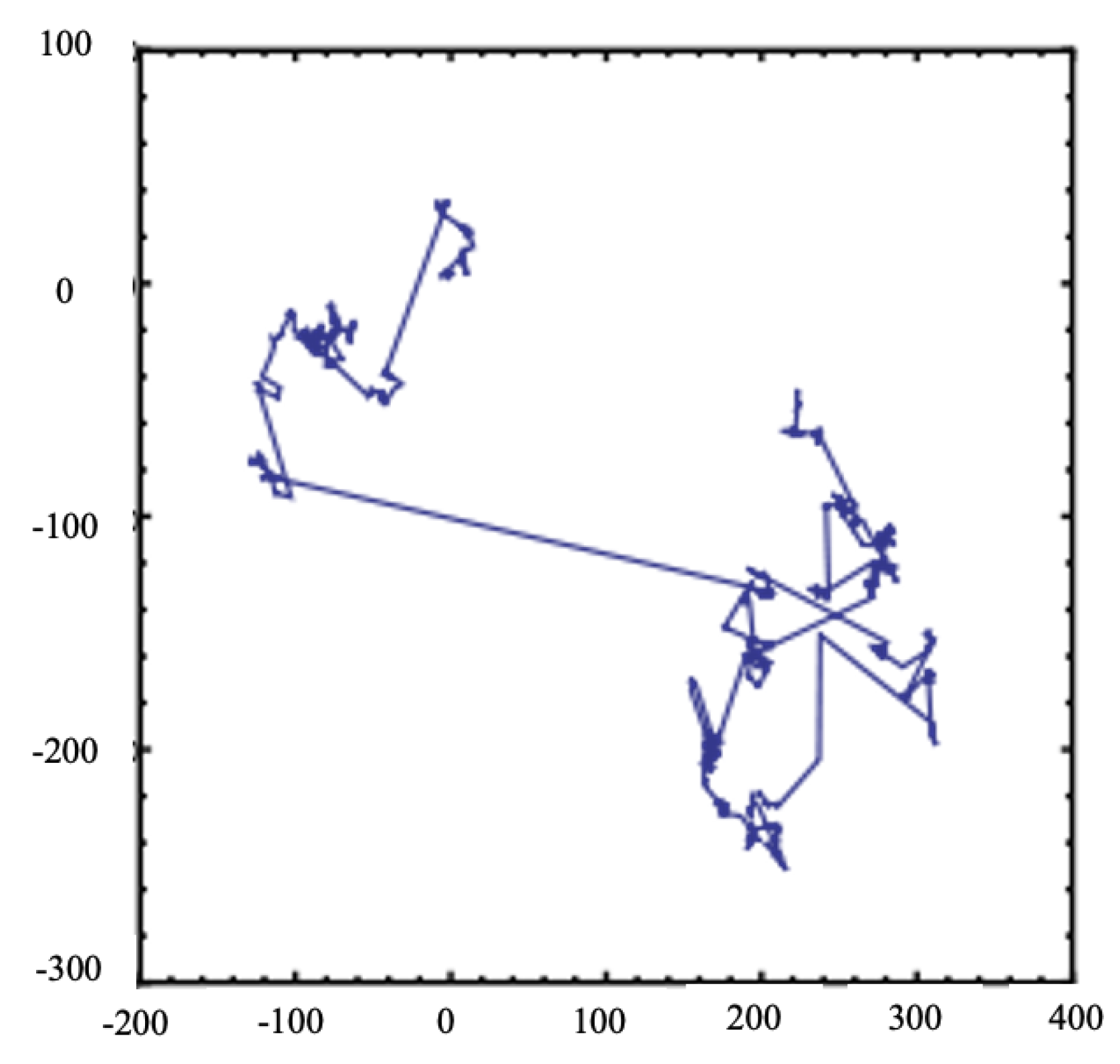
Levy flight is a method of depicting the Levy distribution in random steps. Numerous studies have shown that many animals and insects behave in a way that is classically characteristic of Levy flight. Levy flight is a method of random step size, as shown in Figure 7, a simulated image of the Levy flight trajectory, which always occurs with small step sizes but occasionally occurs with large jumps [46].
The equation for Levy’s flight is as follows:
L e v y μ = t λ , 1 < λ 3
The step s of Levy’s flight is given by
s = μ | v | 1 β
where the parameters β = 1.5 , μ = N 0 , σ μ 2 and v = N 0 , σ v 2 all denote gamma functions.
The variance σ μ of the parameters can be described by the following equation:
σ μ = Γ ( 1 + β ) × sin π × β 2 Γ ( 1 + β ) 2 × β × 2 ( β 1 ) 2 1 β , σ v = 1
Since Levy’s flight has the property of increasing the population diversity and expanding the search range, adding it to Equation (42) can better complete the update of the leader’s position and make it easier to jump out of the local optimum problem. Therefore, the improved mathematical model of the SSA algorithm can be expressed by combining Equations (44) and (42) as follows:
x j 1 = F j + c 1 × u b j l b j + l b j × Levy , c 3 0 F j c 1 × u b j l b j + l b j × Levy , c 3 < 0
The parameter c 1 in Equation (47) is obtained from Equation (43), which enables the optimization algorithm to tighten the optimal value of the fitness function with the increase in the number of iterations. The combination of the parameter c 1 and the Levy flight strengthens the global search capability of the SSA and ensures the optimal value in time. This method not only improves the search intensity of SSA but also increases the diversity of the algorithm. The optimization algorithm ensures that the algorithm can find the optimal value of the algorithm and avoid falling into the local optimum, and the algorithm has better global search capabilities due to its enhanced diversity. The optimization effect of NTSMC can thus be better obtained.

5.3. NTSMC Parameter Optimization Based on Improved SSA

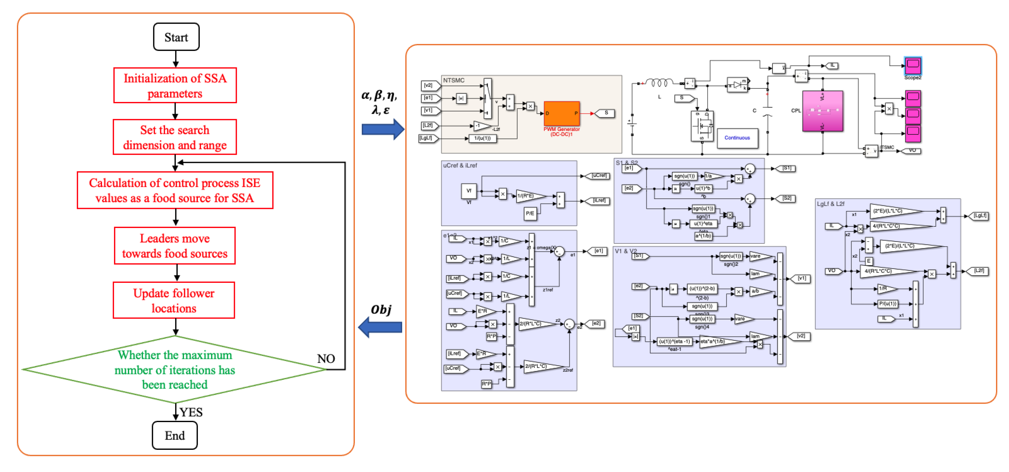
The NTSMC proposed for the voltage stabilization control of the CPL includes several parameters. The values of these parameters significantly influence the performance of the NTSMC. Therefore, the appropriate adjustment of these parameters is required. The number of NTSMC parameters is 5, including the sliding-mode surface parameters α , β , and η (3 parameters) and the convergence law parameters λ and ε (2 parameters). This paper uses an improved SSA (ISSA) to optimize and adjust these parameters. The objective function to be optimized by ISSA is Equation (48). This optimization objective aims to minimize the output voltage’s absolute variation along the time period, as follows:
O b j = 0 T ( u C u C r e f ) 2 d t
In this paper, we used ISSA to search for and solve the optimal values of the sliding-mode surface and convergence law parameters of NTSMC, which transforms the problem of optimizing the parameters into the problem of finding the optimal solution to the objective function. Therefore, in this paper, we used Equation (48) as the fitness function of the ISSA. F j in Equation (47) was used as the food source of the salp leader, and we found the minimum value of Equation (48) more quickly by the predation of the salp swarm on the food, which is the optimal parameter of the NTSMC. The overall optimization flow chart is shown in Figure 8. Therefore, after the optimization of ISSA, it is necessary to obtain the intelligent non-singular terminal sliding-mode control strategy (INTSMC).

6. Numerical Study

In order to verify the effectiveness of the proposed control strategy, a simulation circuit was built in the MATLAB/Simulink platform according to the above discussion. The Boost DC–DC converter system with a CPL based on SMC and the Boost DC–DC converter system with a CPL based on the proposed INTSMC was constructed to further demonstrate the superiority of the controller designed in this paper. The system’s dynamic performance was compared under three conditions: start-up response, input voltage ingestion, and load disturbance, respectively.
The SMC used for comparison has a sliding surface, which can be defined as
S = x 1 x 2 x 1 r e f x 2 r e f
where x 1 ref = i Lref = u cref 2 / R E + P / E ; x 2 r e f = u C r e f . Moreover, this SMC’s sliding-mode convergence law was chosen to be S ˙ = λ S ε s g n S . Therefore, the control law of this SMC can be expressed mathematically as
u = 1 ( P x 1 / C x 2 ) ( E x 2 / L ) λ S ( x 1 2 / C ) ( x 2 2 / L ) + ε s g n ( S ) x 1 2 / C ( x 2 2 / L )
The control parameters of the SMC were then taken from the literature [47].
In this paper, the rated capacity of the converter was 1 kVA, the sampling period was 28 μ s, and the electrical parameters in the CPL system are shown in the following Table 1.
The optimization operating environment was based on the Windows 10 operating system, and MATLAB was used to program the optimization. During optimization, the maximum number of iterations M of the SSA algorithm was ten, and the population size N was 30. Ultimately, the optimal values of these parameters are also given in Table 2.

6.1. Case I: System Start-Up Response

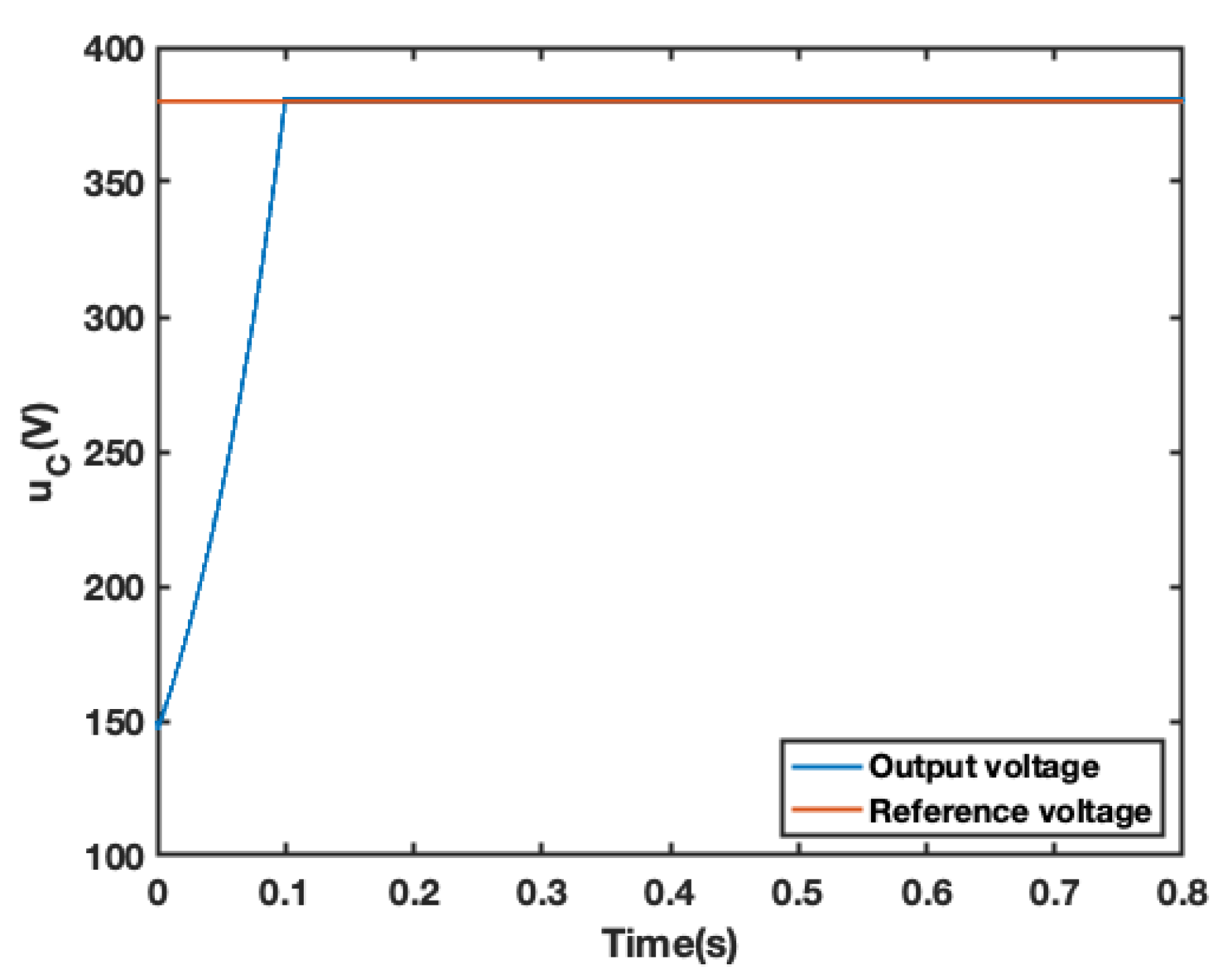
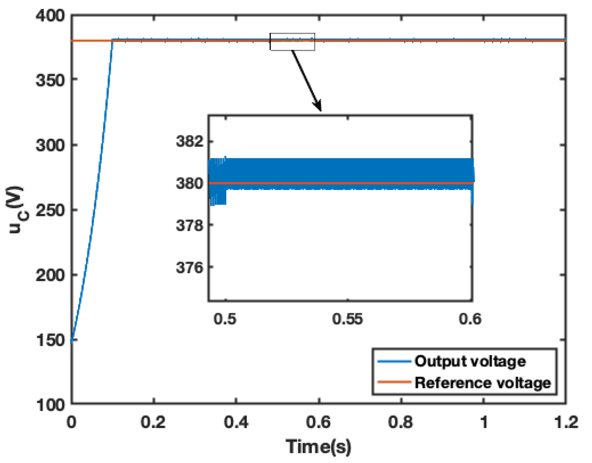
The objective of this study was to evaluate the performance of the Boost DC–DC converter system with CPL under different controllers. We investigated the output voltage and system duty ratio of two systems, as depicted in Figure 9 and Figure 10. In addition, we analyzed the voltage start-up response and duty ratio responses of the two systems.
Our comparative analysis of the voltage start-up response in Figure 9 and Figure 10 reveals that the proposed controller, INTSMC, achieves faster start-up, with the system reaching steady state in about 0.1 seconds and constantly closely tracking its reference value. On the other hand, the system under SMC control takes about 0.4 seconds to enter a steady state. Moreover, the waveform stability of the INTSMC-controlled system is higher, with a lower ripple content after reaching steady state.
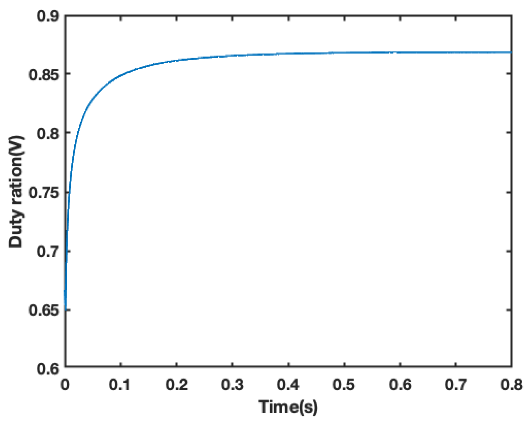
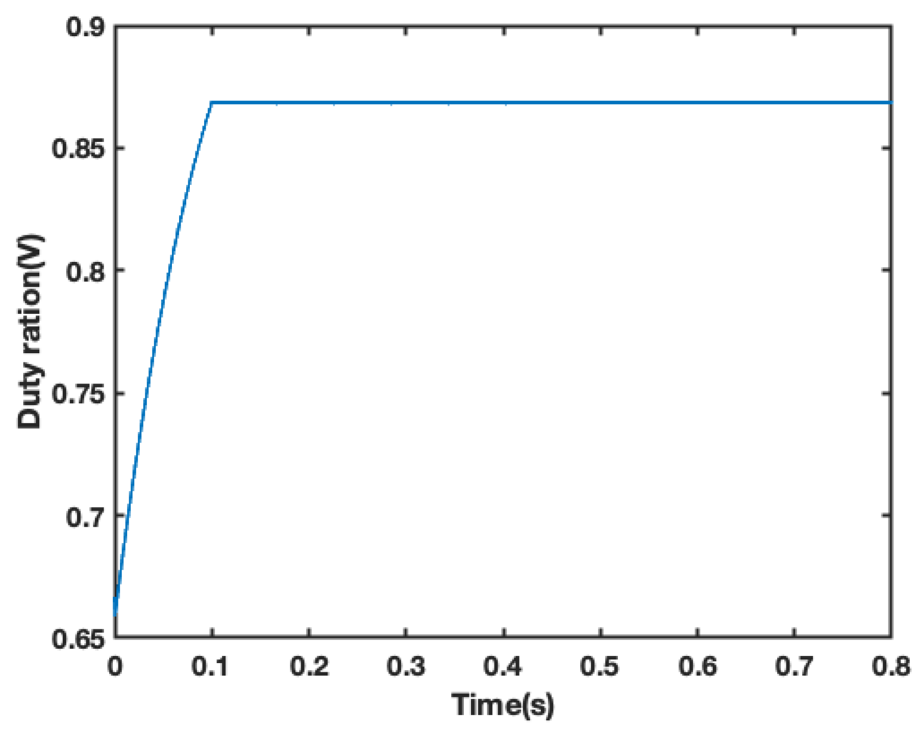
The duty ratio responses of the systems under different controllers are shown in Figure 11 and Figure 12. Both systems exhibit varying degrees of jitter, and the magnitude of jitter in both systems is small, which underscores the advantage of the sliding-mode controller in suppressing jitter.
Overall, our results demonstrate the superiority of the Boost DC–DC converter system with CPL under INTSMC control in terms of faster start-up, higher waveform stability, and lower ripple content. These findings have important implications for the design and optimization of DC–DC converter systems, especially in applications that require stable and fast performance.

6.2. Case II: System Performance during Input Voltage Ingestion

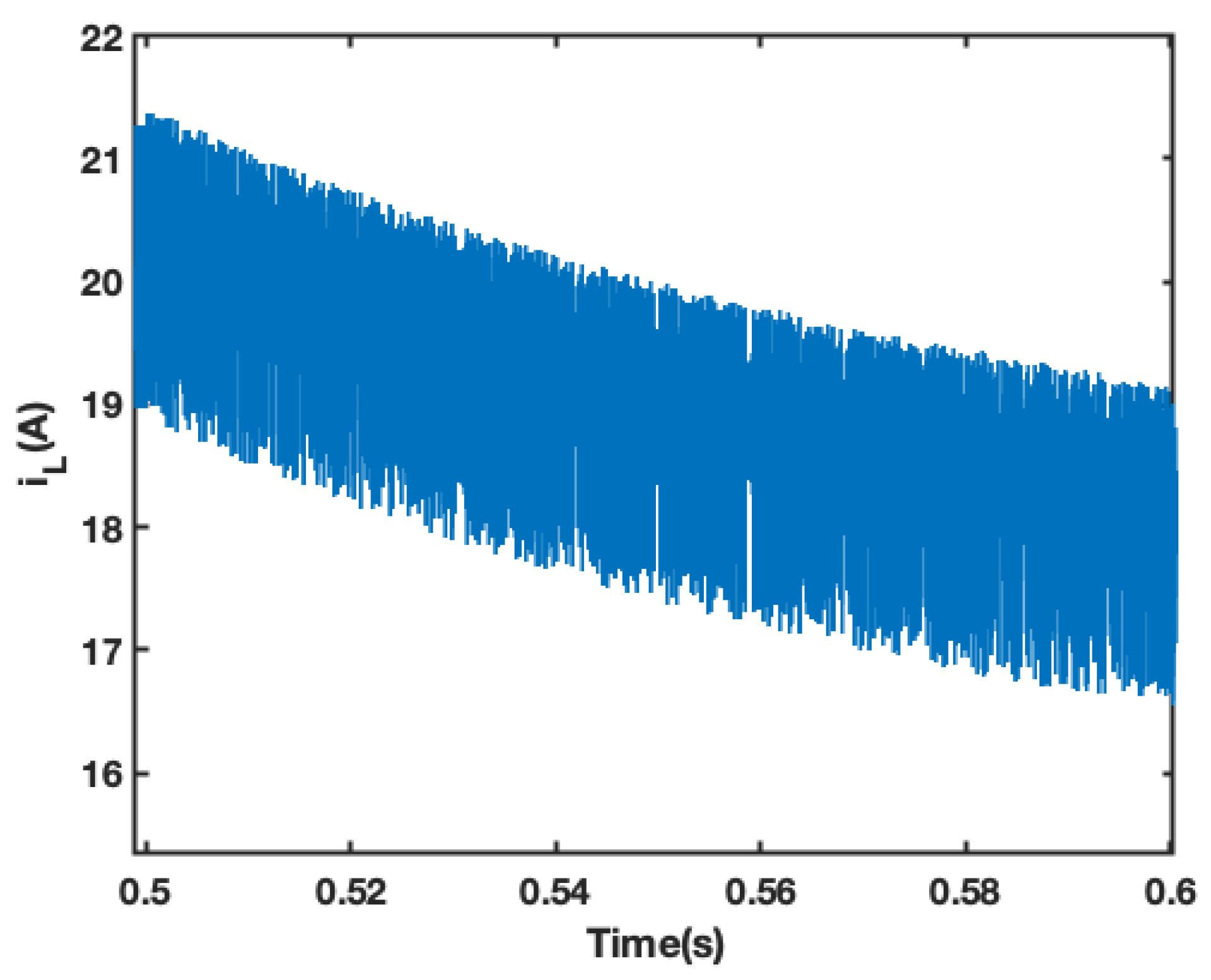
To investigate the robustness of the system during input voltage perturbation, we increased the source-side input voltage from 50 V to 50.25 V in 0.5 s and then recovered it in 0.6 s, as shown in Figure 13. Figure 14 and Figure 15 depict the output voltage responses of the systems under INTSMC and SMC, respectively, when the source-side input voltage is perturbed. In addition, Figure 16 and Figure 17 show the inductor current responses of the two systems under the applied voltage perturbation.
Our results reveal that both the system under INTSMC and the system under SMC deviate from the reference voltage value at the moment of a sudden change in output voltage when the source-side input voltage is perturbed, as observed in Figure 14 and Figure 15. However, the system under INTSMC converges to the steady state faster, with a smaller voltage fluctuation amplitude and ripple and a smoother transition. Furthermore, our analysis demonstrates that the overshoot amplitude of the system under INTSMC is small at the time of the jump in input voltage, allowing it to quickly track the new reference value to ensure the CPL’s power supply. Therefore, the system under INTSMC exhibits greater resistance to disturbances in the input voltage.
Overall, our findings demonstrate the robustness of the Boost DC–DC converter system with CPL under INTSMC control during input voltage perturbation. These results have significant implications for the design and optimization of DC–DC converter systems, particularly in applications where robust performance is critical.

6.3. Case III: Resistance to Load Disturbance

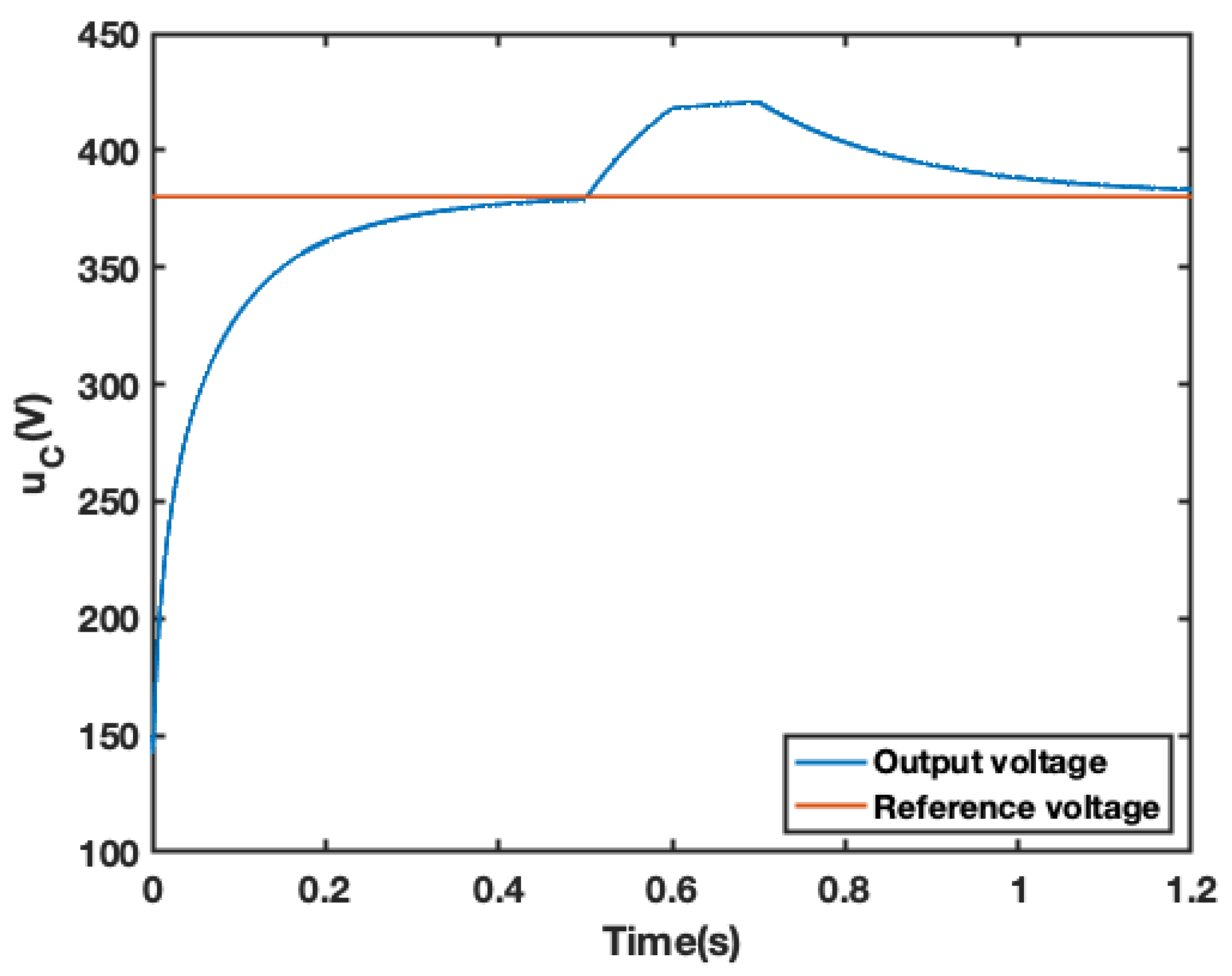
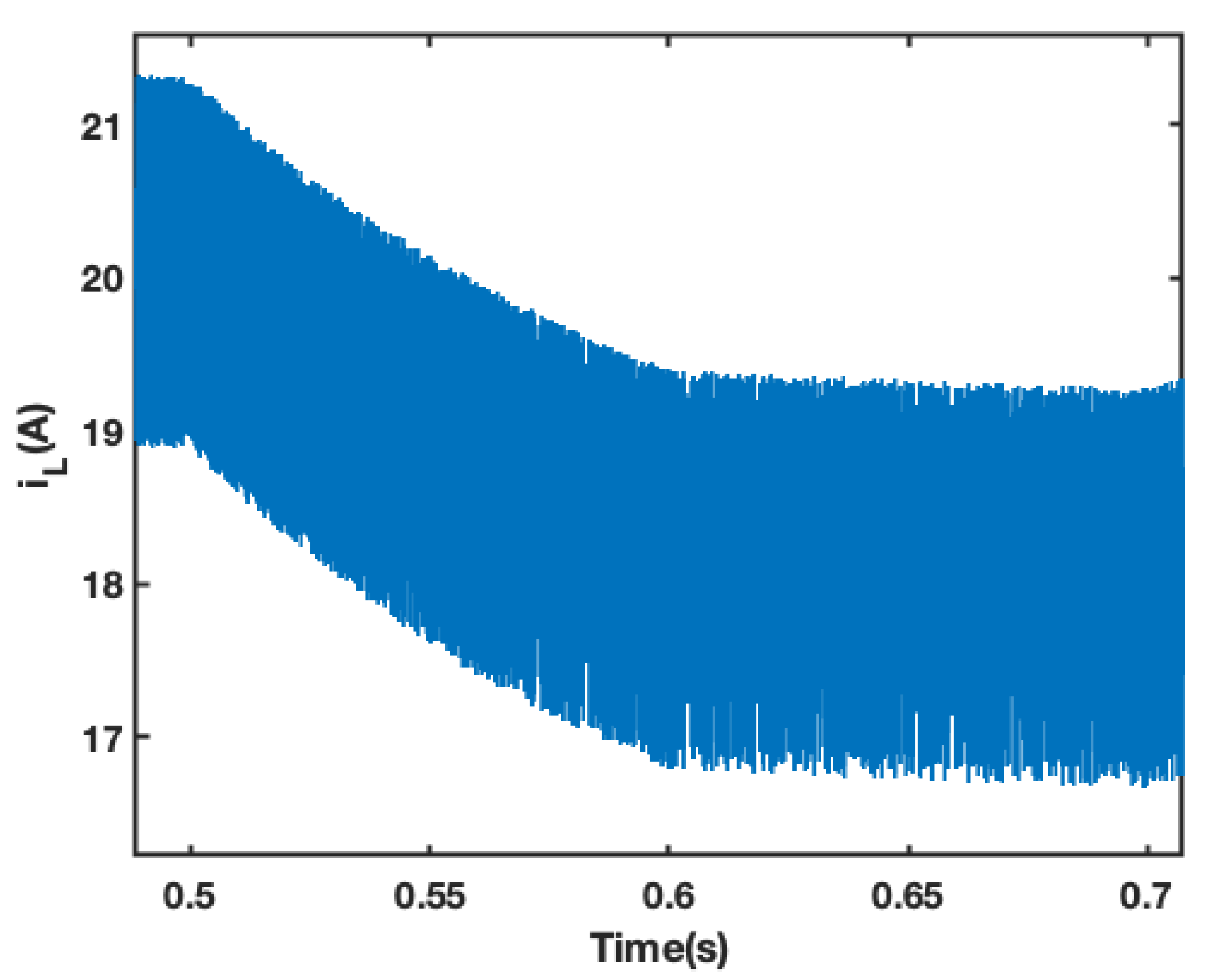
CPL load fluctuation is a significant factor affecting the stability of DC converter systems. In this study, we performed a case simulation to verify the strong robustness of the improved SSA-based INTSMC strategy. As illustrated in Figure 18, we suddenly reduced the CPL power from 1000 W to 800 W at 0.5 s and restored it to 1000 W at 0.7 s to simulate the fluctuation of the CPL’s load.
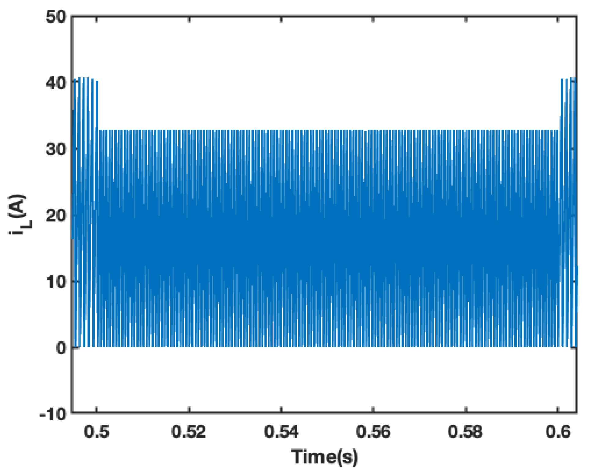
The output voltage and inductor current response waveforms of the two systems under perturbation of the CPL’s load are presented in Figure 19 and Figure 20, respectively. Our comparative analysis in Figure 19 and Figure 20 demonstrates that the output voltage of both systems deviates from the reference voltage value when the CPL changes abruptly. However, the system under INTSMC maintains an unchanged output voltage and always maintains tracking accuracy before the perturbation, indicating better control performance than the system under SMC. Moreover, the comparison of the inductor current response in Figure 21 and Figure 22 further confirms the superior control performance of the proposed INTSMC when the constant power load is disturbed.
Overall, our results indicate that the proposed controller exhibits better dynamic response and robustness to CPL perturbations. These findings have significant implications for the design and optimization of DC converter systems, particularly in applications where stable and robust performance is crucial.

7. Conclusions

Due to the environmental and economic benefits of DCMGs, they provide a strong impetus for the efficient, low-carbon, and sustainable development of power grids. However, the CPL of DCMGs can bring about MG stability problems, which should be suppressed using appropriate controllers. This paper proposes an improved SSA-based non-singular terminal sliding-mode control technique (NTSMC) for targeting the stability problem of Boost DC–DC converter systems with CPL. The improved SSA algorithm is applied to adjust the parameters of the proposed NTSMC optimally. This paper proposes an intelligent NTSMC for the CPL stability problem of DCMG, which was not available before. The simulation results show that the intelligent NTSMC (INTSMC) controller is faster than the conventional SMC controller and can resist disturbances in source-side input voltage and perturbations in the CPL’s load to ensure good dynamic regulation and the steady-state tracking capability of the output voltage and inductor current, thus ensuring the stable and reliable operation of the system. At the same time, the designed controller combines the advantages of state-feedback accurate linearization and sliding-mode variable structure control, which has a substantial engineering practical value.

Author Contributions

Conceptualization, L.L.; methodology, L.L. and Y.Z.; software, L.L. and Y.Z.; validation, Y.Z.; formal analysis, L.L.; investigation, L.L.; resources, Y.Z.; data curation, Y.Z.; writing—original draft preparation, L.L.; writing—review and editing, Y.Z.; project administration, Y.Z.; funding acquisition, Y.Z. All authors have read and agreed to the published version of the manuscript.

Funding

The research reported here is financially supported by the National Natural Science Foundation of China, under grants no. 52079059 and 52269020.

Institutional Review Board Statement

Not applicable.

Informed Consent Statement

Not applicable.

Data Availability Statement

Not applicable.

Acknowledgments

We thank Yonggang Zhu for his contribution to this study.

Conflicts of Interest

The authors declare no conflict of interest.

References

  1. Elmouatamid, A.; Ouladsine, R.; Bakhouya, M.; El Kamoun, N.; Khaidar, M.; Zine-Dine, K. Review of control and energy management approaches in micro-grid systems. Energies 2020, 14, 168. [Google Scholar] [CrossRef]
  2. Vuddanti, S.; Salkuti, S.R. Review of energy management system approaches in microgrids. Energies 2021, 14, 5459. [Google Scholar]
  3. Lopez-Prado, J.L.; Vélez, J.I.; Garcia-Llinas, G.A. Reliability evaluation in distribution networks with microgrids: Review and classification of the literature. Energies 2020, 13, 6189. [Google Scholar] [CrossRef]
  4. Arbab-Zavar, B.; Palacios-Garcia, E.J.; Vasquez, J.C.; Guerrero, J.M. Smart inverters for microgrid applications: A review. Energies 2019, 12, 840. [Google Scholar] [CrossRef] [Green Version]
  5. Ali, S.; Zheng, Z.; Aillerie, M.; Sawicki, J.P.; Pera, M.C.; Hissel, D. A review of DC Microgrid energy management systems dedicated to residential applications. Energies 2021, 14, 4308. [Google Scholar] [CrossRef]
  6. Al-Tameemi, Z.H.A.; Lie, T.T.; Foo, G.; Blaabjerg, F. Control strategies of DC microgrids cluster: A comprehensive review. Energies 2021, 14, 7569. [Google Scholar] [CrossRef]
  7. Fotopoulou, M.; Rakopoulos, D.; Trigkas, D.; Stergiopoulos, F.; Blanas, O.; Voutetakis, S. State of the art of low and medium voltage direct current (Dc) microgrids. Energies 2021, 14, 5595. [Google Scholar] [CrossRef]
  8. Zhang, Q.; Zhuang, X.; Liu, Y.; Wang, C.; Guo, H. A novel autonomous current-sharing control strategy for multiple paralleled DC–DC converters in islanded DC microgrid. Energies 2019, 12, 3951. [Google Scholar] [CrossRef] [Green Version]
  9. Babaei, E.; Saadatizadeh, Z. A new interleaved high voltage gain bidirectional buck-boost DC/DC converter with capability of zero voltage switching. Electr. Power Components Syst. 2019, 47, 1180–1195. [Google Scholar] [CrossRef]
  10. Farsizadeh, H.; Gheisarnejad, M.; Mosayebi, M.; Rafiei, M.; Khooban, M.H. An intelligent and fast controller for DC/DC converter feeding CPL in a DC microgrid. IEEE Trans. Circuits Syst. II: Express Briefs 2019, 67, 1104–1108. [Google Scholar] [CrossRef]
  11. AL-Nussairi, M.K.; Bayindir, R.; Padmanaban, S.; Mihet-Popa, L.; Siano, P. Constant power loads (cpl) with microgrids: Problem definition, stability analysis and compensation techniques. Energies 2017, 10, 1656. [Google Scholar] [CrossRef] [Green Version]
  12. Wu, J.; Lu, Y. Adaptive backstepping sliding mode control for boost converter with constant power load. IEEE Access 2019, 7, 50797–50807. [Google Scholar] [CrossRef]
  13. Liao, J.; You, X.; Liu, H.; Huang, Y. Voltage stability improvement of a bipolar DC system connected with constant power loads. Electr. Power Syst. Res. 2021, 201, 107508. [Google Scholar] [CrossRef]
  14. Singh, S.; Gautam, A.R.; Fulwani, D. Constant power loads and their effects in DC distributed power systems: A review. Renew. Sustain. Energy Rev. 2017, 72, 407–421. [Google Scholar] [CrossRef]
  15. Thounthong, P. Port-Hamiltonian Formulation of Adaptive Hamiltonian PID controller to Solve Constant Power Load Stability Issue in DC Microgrid: Control of a Fuel Cell Converter. In Proceedings of the 2021 IEEE 12th Energy Conversion Congress & Exposition-Asia (ECCE-Asia), Singapore, 24–27 May 2021; pp. 1864–1869. [Google Scholar]
  16. Khaligh, A. Realization of parasitics in stability of DC–DC converters loaded by constant power loads in advanced multiconverter automotive systems. IEEE Trans. Ind. Electron. 2008, 55, 2295–2305. [Google Scholar] [CrossRef]
  17. Cespedes, M.; Xing, L.; Sun, J. Constant-power load system stabilization by passive damping. IEEE Trans. Power Electron. 2011, 26, 1832–1836. [Google Scholar] [CrossRef]
  18. Radwan, A.A.A.; Mohamed, Y.A.R.I. Linear active stabilization of converter-dominated DC microgrids. IEEE Trans. Smart Grid 2011, 3, 203–216. [Google Scholar] [CrossRef]
  19. Shen, X.; Xie, T.; Wang, T. A fuzzy Adaptative Backstepping control strategy for marine current turbine under disturbances and uncertainties. Energies 2020, 13, 6550. [Google Scholar] [CrossRef]
  20. Bjaoui, M.; Khiari, B.; Benadli, R.; Memni, M.; Sellami, A. Practical implementation of the backstepping sliding mode controller MPPT for a PV-storage application. Energies 2019, 12, 3539. [Google Scholar] [CrossRef] [Green Version]
  21. Ghosh, S.K.; Roy, T.K.; Pramanik, M.A.H.; Mahmud, M.A. Design of nonlinear backstepping double-integral sliding mode controllers to stabilize the DC-bus voltage for DC–DC converters feeding CPLs. Energies 2021, 14, 6753. [Google Scholar] [CrossRef]
  22. Yousefizadeh, S.; Bendtsen, J.D.; Vafamand, N.; Khooban, M.H.; Blaabjerg, F.; Dragičević, T. Tracking control for a DC microgrid feeding uncertain loads in more electric aircraft: Adaptive backstepping approach. IEEE Trans. Ind. Electron. 2018, 66, 5644–5652. [Google Scholar] [CrossRef] [Green Version]
  23. Xu, Q.; Zhang, C.; Wen, C.; Wang, P. A novel composite nonlinear controller for stabilization of constant power load in DC microgrid. IEEE Trans. Smart Grid 2017, 10, 752–761. [Google Scholar] [CrossRef]
  24. Chen, Y.T.; Yu, C.S.; Chen, P.N. Feedback linearization based robust control for linear permanent magnet synchronous motors. Energies 2020, 13, 5242. [Google Scholar] [CrossRef]
  25. Li, X.; Chen, X. A Multi-Index Feedback Linearization Control for a Buck-Boost Converter. Energies 2021, 14, 1496. [Google Scholar] [CrossRef]
  26. Mehrasa, M.; Babaie, M.; Sharifzadeh, M.; Al-Haddad, K. An Input–Output Feedback Linearization Control Method Synthesized by Artificial Neural Network for Grid-Tied Packed E-Cell Inverter. IEEE Trans. Ind. Appl. 2021, 57, 3131–3142. [Google Scholar] [CrossRef]
  27. Li, J.; Pan, H.; Long, X.; Liu, B. Objective holographic feedbacks linearization control for boost converter with constant power load. Int. J. Electr. Power Energy Syst. 2022, 134, 107310. [Google Scholar] [CrossRef]
  28. Errouissi, R.; Shareef, H.; Viswambharan, A.; Wahyudie, A. Disturbance-Observer-Based Feedback Linearization Control for Stabilization and Accurate Voltage Tracking of a DC–DC Boost Converter. IEEE Trans. Ind. Appl. 2022, 58, 6687–6700. [Google Scholar] [CrossRef]
  29. Shao, X.; Hu, J.; Zhao, Z. Stabilisation strategy based on feedback linearisation for DC microgrid with multi-converter. J. Eng. 2019, 2019, 1802–1806. [Google Scholar] [CrossRef]
  30. Majout, B.; Bossoufi, B.; Bouderbala, M.; Masud, M.; Al-Amri, J.F.; Taoussi, M.; Karim, M. Improvement of PMSG-based wind energy conversion system using developed sliding mode control. Energies 2022, 15, 1625. [Google Scholar] [CrossRef]
  31. Benbouhenni, H.; Bizon, N. A synergetic sliding mode controller applied to direct field-oriented control of induction generator-based variable speed dual-rotor wind turbines. Energies 2021, 14, 4437. [Google Scholar] [CrossRef]
  32. Al Zawaideh, A.; Boiko, I.M. Analysis of stability and performance of a cascaded PI sliding-mode control DC–DC boost converter via LPRS. IEEE Trans. Power Electron. 2022, 37, 10455–10465. [Google Scholar] [CrossRef]
  33. Armghan, H.; Yang, M.; Armghan, A.; Ali, N.; Wang, M.Q.; Ahmad, I. Design of integral terminal sliding mode controller for the hybrid AC/DC microgrids involving renewables and energy storage systems. Int. J. Electr. Power Energy Syst. 2020, 119, 105857. [Google Scholar] [CrossRef]
  34. Zheng, C.; Dragičević, T.; Zhang, J.; Chen, R.; Blaabjerg, F. Composite robust quasi-sliding mode control of DC–DC buck converter with constant power loads. IEEE J. Emerg. Sel. Top. Power Electron. 2020, 9, 1455–1464. [Google Scholar] [CrossRef]
  35. El Aroudi, A.; Martinez-Trevino, B.A.; Vidal-Idiarte, E.; Cid-Pastor, A. Fixed switching frequency digital sliding-mode control of DC–DC power supplies loaded by constant power loads with inrush current limitation capability. Energies 2019, 12, 1055. [Google Scholar] [CrossRef] [Green Version]
  36. Yang, P.; Ma, X.; Wang, J.; Zhang, G.; Zhang, Y.; Chen, L. Disturbance observer-based terminal sliding mode control of a 5-DOF upper-limb exoskeleton robot. IEEE Access 2019, 7, 62833–62839. [Google Scholar] [CrossRef]
  37. Wang, J.; Li, S.; Yang, J.; Wu, B.; Li, Q. Finite-time disturbance observer based non-singular terminal sliding-mode control for pulse width modulation based DC–DC buck converters with mismatched load disturbances. IET Power Electron. 2016, 9, 1995–2002. [Google Scholar] [CrossRef]
  38. Zou, Y.; Hu, W.; Xiao, Z.; Wang, Y.; Chen, J.; Zheng, Y.; Zeng, Y. Design of intelligent nonlinear robust controller for hydro-turbine governing system based on state-dynamic-measurement hybrid feedback linearization method. Renew. Energy 2023, 204, 635–651. [Google Scholar] [CrossRef]
  39. Bacha, S.; Munteanu, I.; Bratcu, A.I. Power electronic converters modeling and control. Adv. Textb. Control. Signal Process. 2014, 454, 454. [Google Scholar]
  40. Lu, Q.; Sun, Y.; Mei, S. Nonlinear Control Systems and Power System Dynamics; Springer Science & Business Media: Berlin, Germany, 2001. [Google Scholar]
  41. Zhou, K.; Ai, M.; Sun, D.; Jin, N.; Wu, X. Field weakening operation control strategies of PMSM based on feedback linearization. Energies 2019, 12, 4526. [Google Scholar] [CrossRef] [Green Version]
  42. Rahimi, A.M.; Emadi, A. Active damping in DC/DC power electronic converters: A novel method to overcome the problems of constant power loads. IEEE Trans. Ind. Electron. 2009, 56, 1428–1439. [Google Scholar] [CrossRef]
  43. Tudose, A.M.; Picioroaga, I.I.; Sidea, D.O.; Bulac, C. Solving single-and multi-objective optimal reactive power dispatch problems using an improved salp swarm algorithm. Energies 2021, 14, 1222. [Google Scholar] [CrossRef]
  44. Zishan, F.; Mansouri, S.; Abdollahpour, F.; Grisales-Noreña, L.F.; Montoya, O.D. Allocation of Renewable Energy Resources in Distribution Systems while Considering the Uncertainty of Wind and Solar Resources via the Multi-Objective Salp Swarm Algorithm. Energies 2023, 16, 474. [Google Scholar] [CrossRef]
  45. Tightiz, L.; Mansouri, S.; Zishan, F.; Yoo, J.; Shafaghatian, N. Maximum Power Point Tracking for Photovoltaic Systems Operating under Partially Shaded Conditions Using SALP Swarm Algorithm. Energies 2022, 15, 8210. [Google Scholar] [CrossRef]
  46. Fan, Y.; Shao, J.; Sun, G.; Shao, X. Proportional–integral–derivative controller design using an advanced lévy-flight salp swarm algorithm for hydraulic systems. Energies 2020, 13, 459. [Google Scholar] [CrossRef] [Green Version]
  47. Singh, S.; Fulwani, D.; Kumar, V. Robust sliding-mode control of dc/dc boost converter feeding a constant power load. IET Power Electron. 2015, 8, 1230–1237. [Google Scholar] [CrossRef]
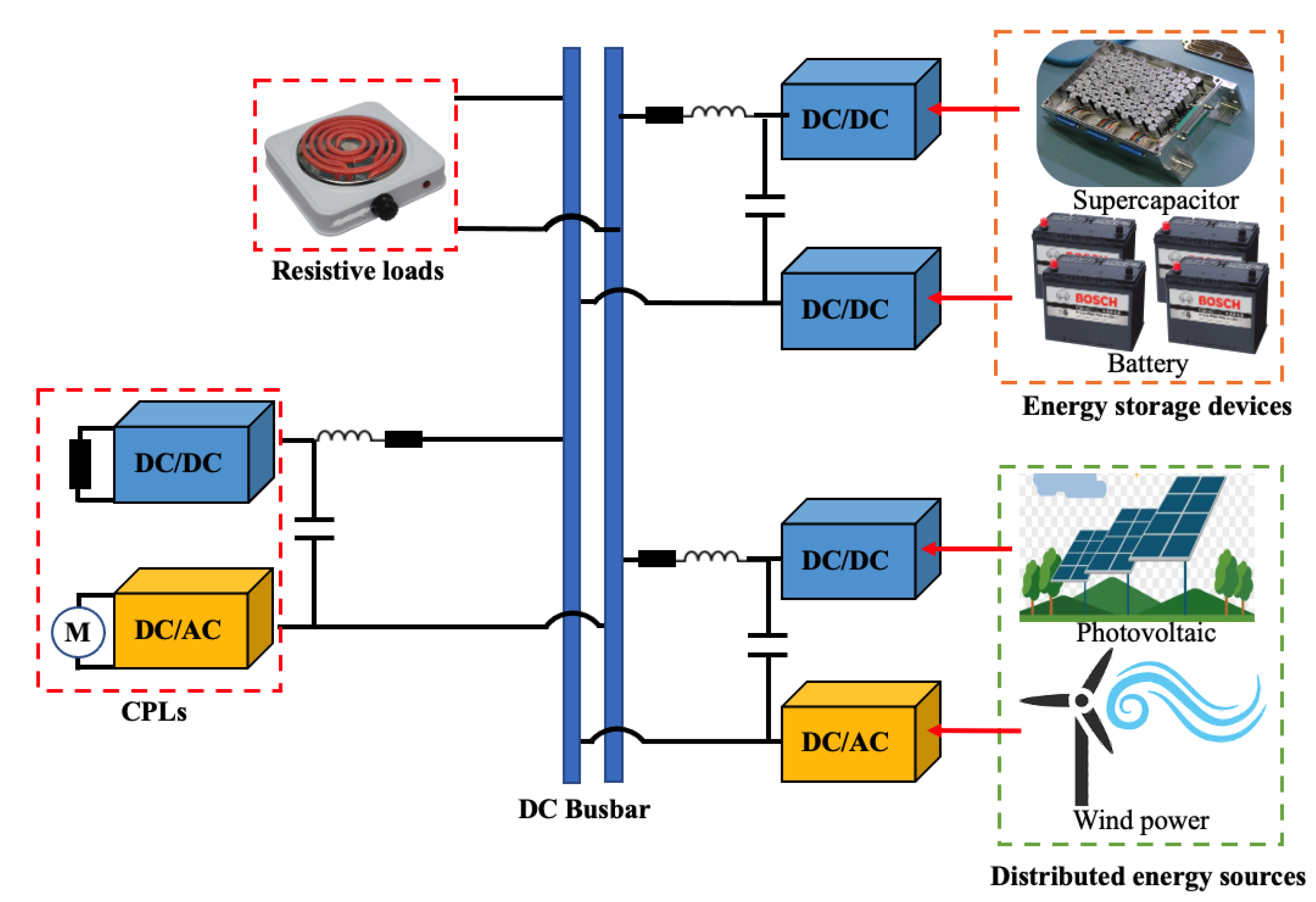
Figure 1. Structure of typical DC microgrid system.
Energies 16 04973 g001
Figure 2. Boost DC converter topology with CPL and resistive load.
Energies 16 04973 g002
Figure 3. Operating Mode 1.
Energies 16 04973 g003
Figure 4. Operating Mode 2.
Energies 16 04973 g004
Figure 5. Voltage–current characteristics of CPL.
Energies 16 04973 g005
Figure 6. Shape and structure of salp chain in deep ocean.
Energies 16 04973 g006
Figure 7. Levy’s flight path.
Energies 16 04973 g007
Figure 8. Parameters optimization algorithm flow chart.
Energies 16 04973 g008
Figure 9. Voltage start-response waveform under SMC.
Energies 16 04973 g009
Figure 10. Voltage start-response waveform under INTSMC.
Energies 16 04973 g010
Figure 11. System duty ration under SMC.
Energies 16 04973 g011
Figure 12. System duty ration under INTSMC.
Energies 16 04973 g012
Figure 13. Input voltage change curve.
Energies 16 04973 g013
Figure 14. Voltage response waveform under SMC.
Energies 16 04973 g014
Figure 15. Voltage response waveform under INTSMC.
Energies 16 04973 g015
Figure 16. Current response waveform under SMC.
Energies 16 04973 g016
Figure 17. Current response waveform under INTSMC.
Energies 16 04973 g017
Figure 18. CPL power change curve.
Energies 16 04973 g018
Figure 19. Voltage response waveform under SMC.
Energies 16 04973 g019
Figure 20. Voltage response waveform under INTSMC.
Energies 16 04973 g020
Figure 21. Current response waveform under SMC.
Energies 16 04973 g021
Figure 22. Current response waveform under INTSMC.
Energies 16 04973 g022
Table 1. System’s electrical parameters.
ParameterValue
Reference output voltage u C r e f 380 V
Input inductance L1 mH
Output capacitance C1000  μ F
Power supply nominal voltage E50 V
CPL power P1000 W
Table 2. INTSMC optimal control parameters.
Parameter α β η λ ε
Value 7.06 × 10 4 5.88 × 10 4 8.24 × 10 4 3.51 × 10 4 7.03 × 10 4
Disclaimer/Publisher’s Note: The statements, opinions and data contained in all publications are solely those of the individual author(s) and contributor(s) and not of MDPI and/or the editor(s). MDPI and/or the editor(s) disclaim responsibility for any injury to people or property resulting from any ideas, methods, instructions or products referred to in the content.