


Review of Developments in Plate Heat Exchanger Heat Transfer Enhancement for Single-Phase Applications in Process Industries

 ,
,  and
and 
Abstract
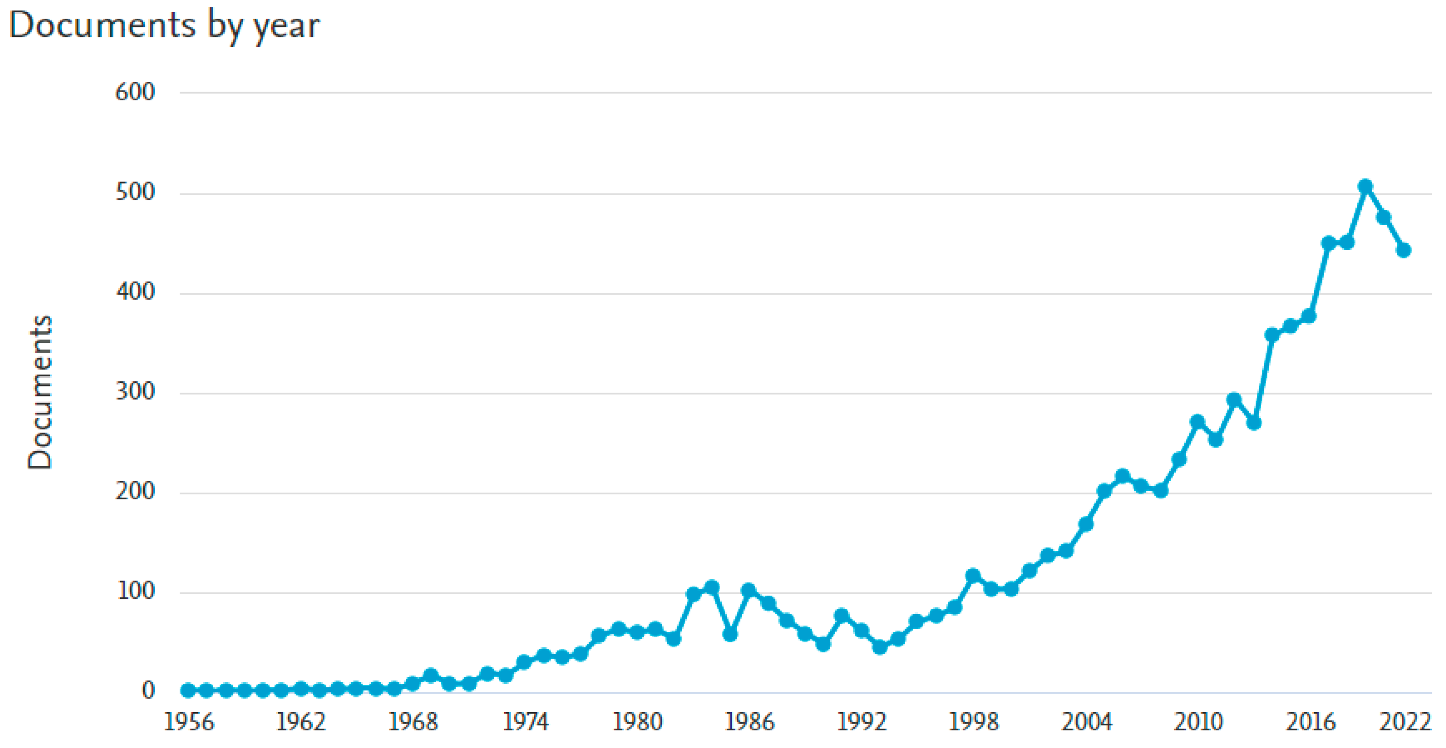
1. Introduction
2. PHEs and Their Types of Construction
- (i)
- A large number of contact points between adjacent plates in the plate pack that form a strong structure capable of withstanding large differential pressures between streams in channels [10]. This allows for plates of small thicknesses down to about 0.3 mm, decreasing the consumption of costly metals and the PHE weight;
- (ii)
- The PHE channels with contact points for the corrugations inside have a geometrical form inducing a change in flow direction and high levels of turbulence, swirl and vortex structures. This happens even at relatively low Reynolds numbers, as shown by various researchers (see, e.g., [11]). It creates a peculiar mechanism of heat transfer enhancement with a rather smooth transition from a laminar to a turbulent flow regime;
- (iii)
- Heat transfer coefficients in PHEs are much higher than in traditional shell-and-tube heat exchangers, and a significantly smaller heat transfer area is required, which makes them much more compact, with smaller area needs for maintenance;
- (iv)
- The area of the heat transfer surface in PHEs is made of thin metal plates and requires much less material than in shell-and-tube heat exchangers. This makes it possible to achieve lower costs, even when more expensive materials are used [12];
- (v)
- Often, the temperature approach of the streams in PHEs can be reduced to 1 °C, which makes them useful for maximal heat recuperation in heat exchanger networks (HENs) [13];
- (vi)
- By adjusting the geometries of plate corrugations, the performance of PHEs can be optimised for specific process conditions [14]. This can be achieved by assembling one of the PHEs from plates with different corrugations that enable close (within an error of one plate) satisfaction of the required duty;
- (vii)
- The low weight of PHEs means lower costs for transport and fewer requirements for the foundation;
- (viii)
- The low hold-up volume of PHEs with narrow channels makes them suitable for treating dangerous or expensive fluids. Low PHE weight ensures easier control of process parameters;
- (ix)
- The possibility of handling multiple streams in one PHE enables the simplification of the process unit and increases its compactness;
- (x)
- Easy disassembly of plate-and-frame PHEs enables mechanical cleaning, rearranging and changing of a number of plates to flexibly satisfy the required changes in process requirements;
- (xi)
- The heat losses to surroundings in PHEs are considerably reduced, as the plates are in contact with ambient air only at their side edges.
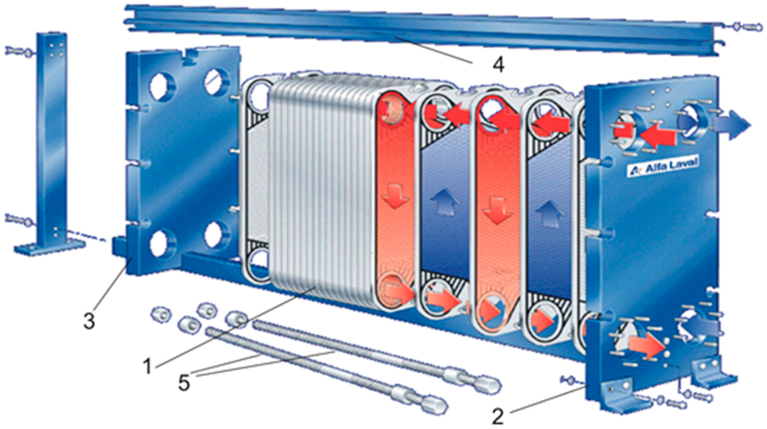
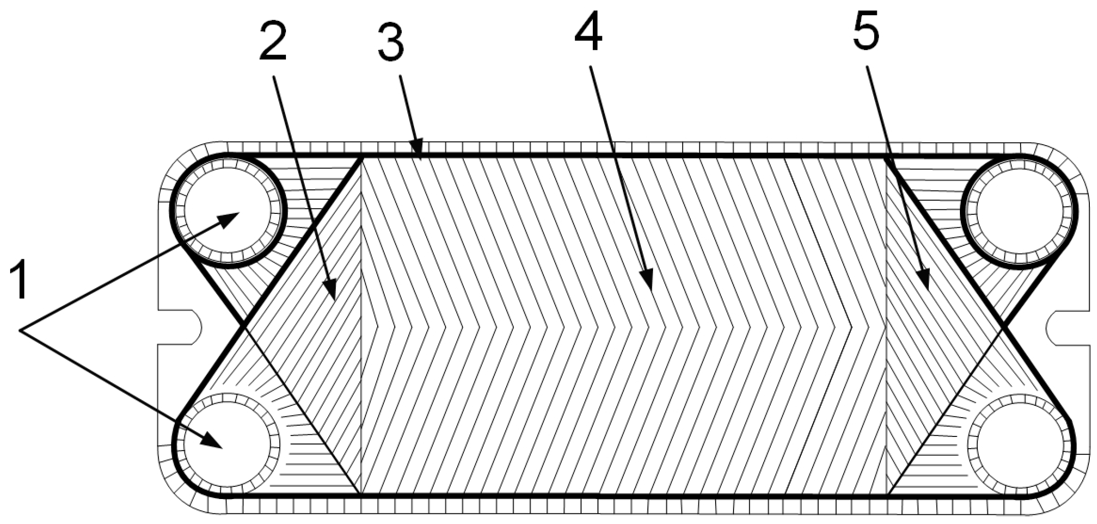
2.1. Plate-and-Frame PHEs
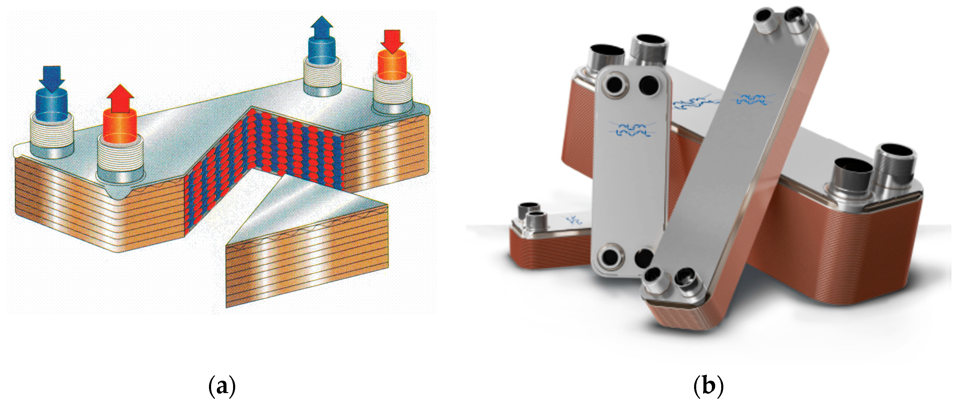
2.2. Brazed PHEs
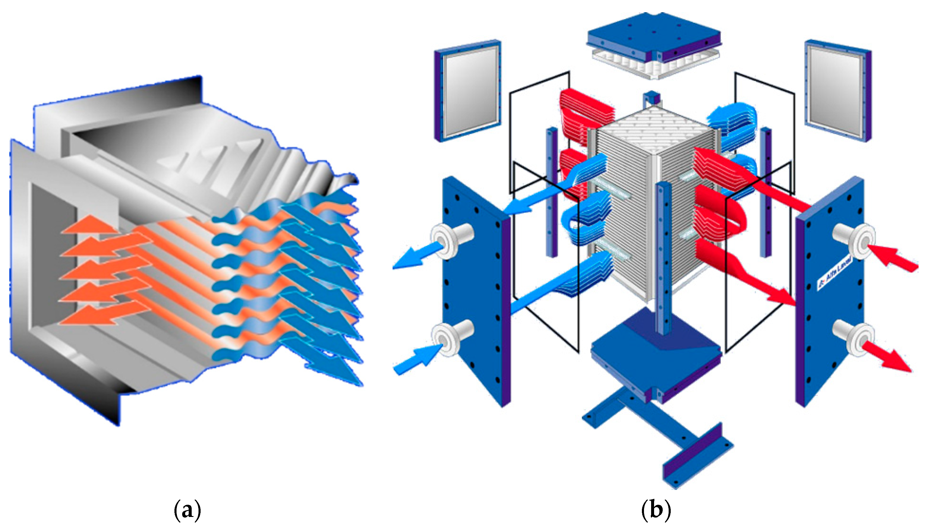
2.3. Welded PHEs
2.3.1. Welded Plate-and-Frame PHEs
2.3.2. Welded Plate-and-Block PHEs
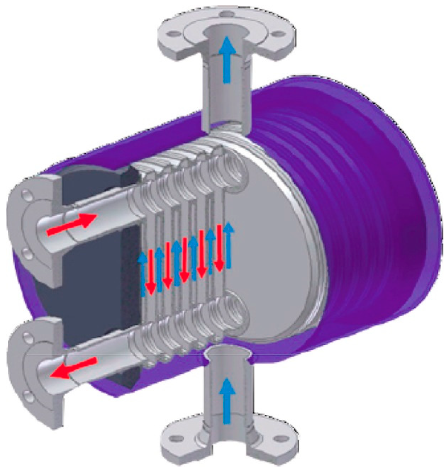
2.3.3. Welded Plate-and-Shell PHEs
3. PHE Thermal and Hydraulic Performance
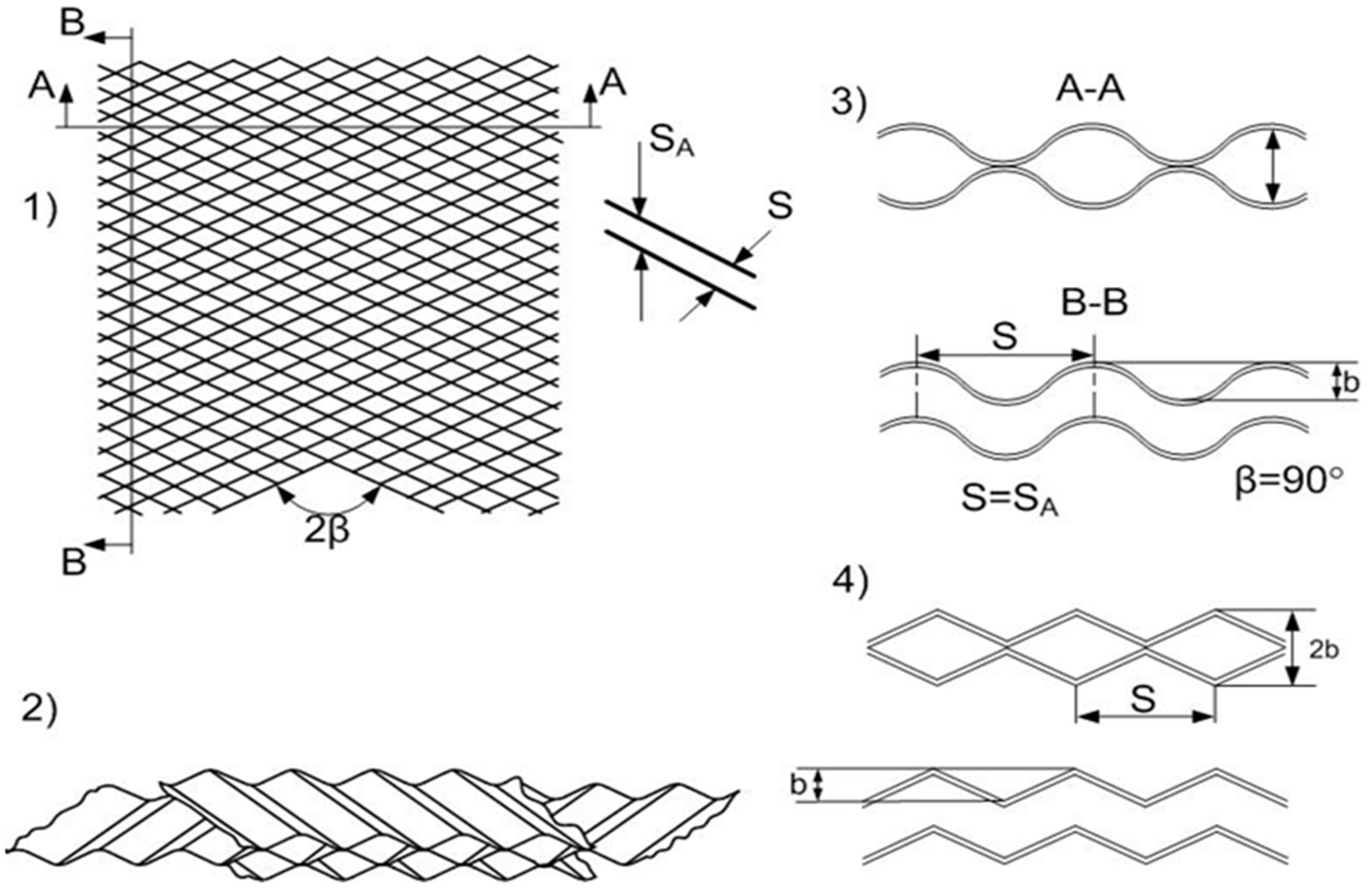
3.1. Experimental Studies on PHEs with Chevron-Type Corrugated Plates
3.2. CFD Modelling of Hydrodynamics and Heat Transfer in PHE Channels
4. Intensification of Heat Transfer in PHE Channels
4.1. Passive Methods through Modification of the Channel Surface Geometry
4.1.1. Asterisk, Compound and Special Transverse Forms of Corrugations
4.1.2. Undulated Corrugations with Surface Optimisation
4.1.3. New Forms of Plates and Corrugations for Cross-Flow and Mixed-Flow PHEs
4.1.4. Capsule-Type and Dimpled Special Forms of Corrugations
4.1.5. Optimisation of Chevron-Type Corrugations
4.1.6. Modifications of Plate Surface with Artificial Roughness
4.2. Heat Transfer Enhancement through the Use of Nanofluids
4.3. Heat Transfer Enhancement with Active Methods
5. PHEs in Various Applications as Individual Units and in Heat Exchanger Networks
6. Conclusions
Author Contributions
Funding
Data Availability Statement
Conflicts of Interest
References
- United States Environmental Protection Agency. Sources of Greenhouse Gas Emissions. 2022. Available online: https://www.epa.gov/ghgemissions/sources-greenhouse-gas-emissions (accessed on 17 July 2022).
- European Parliament News. EU Responses to Climate Change. 2022. Available online: https://www.europarl.europa.eu/news/en/headlines/society/20180703STO07129/eu-responses-to-climate-change (accessed on 17 July 2022).
- Hesselgreaves, J.E.; Law, R.; Reay, D. Compact Heat Exchangers: Selection, Design and Operation; Butterworth-Heinemann: Oxford, UK, 2016. [Google Scholar]
- Wang, L.; Sunden, B.; Manglik, R.M. PHEs. Design, Applications and Performance; WIT Press: Southhampton, UK, 2007. [Google Scholar]
- Abu-Khader, M.M. Plate heat exchangers: Recent advances. Renew. Sustain. Energy Rev. 2012, 16, 1883–1891. [Google Scholar] [CrossRef]
- Zhang, J.; Zhu, X.; Mondejar, M.E.; Haglind, F. A review of heat transfer enhancement techniques in plate heat exchangers. Renew. Sustain. Energy Rev. 2019, 101, 305–328. [Google Scholar] [CrossRef]
- Kumar, S.; Singh, S.K.; Sharma, D. A Comprehensive Review on Thermal Performance Enhancement of Plate Heat Exchanger. Int. J. Thermophys. 2022, 43, 109. [Google Scholar] [CrossRef]
- Ma, Y.; Xie, G.; Hooman, K. Review of printed circuit heat exchangers and its applications in solar thermal energy. Renew. Sustain. Energy Rev. 2021, 155, 111933. [Google Scholar] [CrossRef]
- Lalagi, G.; Nagaraj, P.B.; Veerabhadrappa Bidari, M.; Hegde, R.N. Influence of design of microchannel heat exchangers and use of nanofluids to improve the heat Transfer and Pressure drop characteristics: A review. Int. J. Ambient. Energy 2022, 43, 6849–6877. [Google Scholar] [CrossRef]
- Martins, G.S.M.; Santiago, R.S.; Beckedorff, L.E.; Possamai, T.S.; Oba, R.; Oliveira, J.L.G.; de Oliveira, A.A.M.; Paiva, K.V. Structural analysis of gasketed plate heat exchangers. Int. J. Press. Vessel. Pip. 2022, 197, 104634. [Google Scholar] [CrossRef]
- Dović, D.; Horvat, I.; Filipović, P. Impact of velocities and geometry on flow components and heat transfer in plate heat exchangers. Appl. Therm. Eng. 2021, 197, 117371. [Google Scholar] [CrossRef]
- Hajabdollahi, H.; Naderi, M.; Adimi, S. A comparative study on the shell and tube and gasket-plate heat exchangers: The economic viewpoint. Appl. Therm. Eng. 2016, 92, 271–282. [Google Scholar] [CrossRef]
- Wang, B.; Arsenyeva, O.; Zeng, M.; Klemeš, J.J.; Varbanov, P.S. An advanced Grid Diagram for heat exchanger network retrofit with detailed plate heat exchanger design. Energy 2022, 248, 123485. [Google Scholar] [CrossRef]
- Arsenyeva, O.; Kapustenko, P.; Tovazhnyanskyy, L.; Khavin, G. The influence of plate corrugations geometry on plate heat exchanger performance in specified process conditions. Energy 2013, 57, 201–207. [Google Scholar] [CrossRef]
- Kabil, B. Parameter Study of the Diagonal on a Gasketed Plate Heat Exchanger. Master’s Dissertation, Division of Solid Mechanics, Lund University, Lund, Sweden, 2022. [Google Scholar]
- AlfaLaval. Types of Gasketed Plate Heat Exchangers. 2022. Available online: https://www.alfalaval.com/microsites/gphe/types/ (accessed on 24 June 2023).
- de Souza, E.L.; de Souza Zanzi, M.; de Paiva, K.V.; Goes Oliveira, J.L.; Monteiro, A.S.; de Oliveira Barra, G.M.; Dutra, G.B. Evaluation of the aging of elastomeric acrylonitrile-butadiene rubber and ethylene-propylene-diene monomer gaskets used to seal plates heat exchanger. Polym. Eng. Sci. 2021, 61, 3001–3016. [Google Scholar] [CrossRef]
- Zanzi, M.S.; de Souza, E.L.; Dutra, G.B.; Paiva, K.V.; Oliveira, J.L.G.; Cunha, T.V.; Monteiro, A.S. Service lifetime prediction of nitrile butadiene rubber gaskets used in plate heat exchangers. J. Appl. Polym. Sci. 2022, 139, 52523. [Google Scholar] [CrossRef]
- Tian, C.; Zhang, D.-W.; Zhang, Q.; Zheng, Z.B.; Zhao, S.D. A drawing-flaring process of metal bushing ring without welding seam for plate heat exchanger. Int. J. Adv. Manuf. Technol. 2022, 121, 2539–2552. [Google Scholar] [CrossRef]
- Trelleborg Sealing Solutions Plate Heat Exchanger Gaskets. 2022. Available online: https://www.trelleborg.com/en/seals/products-and-solutions/engineered-molded-parts/plate-heat-exchanger-gaskets (accessed on 24 June 2023).
- Hashimoto, A.; Liu, S.B.; Shohji, I.; Kobayashi, T.; Hirohashi, J.; Wake, T.; Arai, S.; Kamakoshi, Y. Brazing of Stainless Steel Using Electrolytic Ni-P Plating Film and Investigation of Corrosion Behavior. Mater. Sci. Forum 2021, 1016, 522–527. [Google Scholar] [CrossRef]
- AlfaLaval. Plate Heat Exchangers. 2022. Available online: https://www.alfalaval.com/products/heat-transfer/plate-heat-exchangers/plate-heat-exchangers/ (accessed on 24 June 2023).
- Tovazhnyanskyy, L.; Klemeš, J.J.; Kapustenko, P.; Arsenyeva, O.; Perevertaylenko, O.; Arsenyev, P. Optimal Design of Welded Plate Heat Exchanger for Ammonia Synthesis Column: An Experimental Study with Mathematical Optimisation. Energies 2020, 13, 2847. [Google Scholar] [CrossRef]
- Freire, L.O.; de Andrade, D.A. On applicability of plate and shell heat exchangers for steam generation in naval PWR. Nucl. Eng. Des. 2014, 280, 619–627. [Google Scholar] [CrossRef]
- Vahterus. PSHE Construction. 2022. Available online: https://vahterus.com/technology/pshe-construction/ (accessed on 24 June 2023).
- Martins, G.S.M.; da Silva, R.P.P.D.; Beckedorff, L.; Monteiro, A.S.; de Paiva, K.V.; Oliveira, J.L.G. Fatigue performance evaluation of plate and shell heat exchangers. Int. J. Press. Vessel. Pip. 2020, 188, 104237. [Google Scholar] [CrossRef]
- Joybari, M.M.; Selvnes, H.; Sevault, A.; Hafner, A. Potentials and challenges for pillow-plate heat exchangers: State-of-the-art review. Appl. Therm. Eng. 2022, 214, 118739. [Google Scholar] [CrossRef]
- Savostin, A.F.; Tikhonov, A.M. Investigation of the characteristics of the plate heating surfaces. Therm. Eng. 1970, 17, 113–117. [Google Scholar]
- Rosenblad, G.; Kullendorff, A. Estimating heat transfer rates from mass transfer studies on plate heat exchanger surfaces. Wärme-Und Stoffübertra. 1975, 8, 187–191. [Google Scholar] [CrossRef]
- Tovazhnyansky, L.L.; Kapustenko, P.A.; Tsibulnic, V.A. Heat Transfer and Hydraulic Resistance in Channels of Plate Heat Exchangers. Energetika 1980, 9, 123–125. [Google Scholar]
- Focke, W.W.; Zachariades, J.; Olivier, I. The effect of the corrugation inclination angle on the thermohydraulic performance of plate heat exchangers. Int. J. Heat Mass Transf. 1985, 28, 1469–1479. [Google Scholar] [CrossRef]
- Gaiser, G.; Kottke, V. Flow phenomena and local heat and mass transfer in corrugated passages. Chem. Eng. Technol. 1989, 12, 400–405. [Google Scholar] [CrossRef]
- Heavner, R.L.; Kumar, H.; Wanniarachchi, A.S. Performance of an Industrial Plate Heat Exchanger: Effect of Chevron Angle; AIChE Symposium Series; American Institute of Chemical Engineers: New York, NY, USA, 1993; Volume 89, pp. 262–267. [Google Scholar]
- Bogaert, R.; Bölcs, A. Global performance of a prototype brazed plate heat exchanger in a large Reynolds number range. Exp. Heat Transf. 1995, 8, 293–311. [Google Scholar] [CrossRef]
- Muley, A.; Manglik, R.M.; Metwally, H.M. Enhanced heat transfer characteristics of viscous liquid flows in a chevron plate heat exchanger. J. Heat Transf. 1999, 121, 1011–1017. [Google Scholar] [CrossRef]
- Muley, A.; Manglik, R.M. Experimental study of turbulent flow heat transfer and pressure drop in a plate heat exchanger with chevron plates. ASME J. Heat Transf. 1999, 121, 110–117. [Google Scholar] [CrossRef]
- Zimmerer, C.; Gschwind, P.; Gaiser, G.; Kottke, V. Comparison of heat and mass transfer in different heat exchanger geometries with corrugated walls. Exp. Therm. Fluid Sci. 2002, 26, 269–273. [Google Scholar] [CrossRef]
- Wang, Q.W.; Zhang, D.J.; Xie, G.N. Experimental study and genetic-algorithm-based correlation on pressure drop and heat transfer performances of a cross-corrugated primary surface heat exchanger. Trans. ASME J. Heat Transf. 2009, 131, 061802. [Google Scholar] [CrossRef]
- Dović, D.; Palm, B.; Švaić, S. Generalized correlations for predicting heat transfer and pressure drop in plate heat exchanger channels of arbitrary geometry. Int. J. Heat Mass Transf. 2009, 52, 4553–4563. [Google Scholar] [CrossRef]
- Khan, T.S.; Khan, M.S.; Chyu, M.C.; Ayub, Z.H. Experimental investigation of single phase convective heat transfer coefficient in a corrugated plate heat exchanger for multiple plate configurations. Appl. Therm. Eng. 2010, 30, 1058–1065. [Google Scholar] [CrossRef]
- Gherasim, I.; Taws, M.; Galanis, N.; Nguyen, C.T. Heat transfer and fluid flow in a plate heat exchanger part I. Experimental investigation. Int. J. Therm. Sci. 2011, 50, 1492–1498. [Google Scholar] [CrossRef]
- Shaji, K.; Das, S.K. Effect of plate characteristics on axial dispersion and heat transfer in plate heat exchangers. Trans. ASME J. Heat Transf. 2013, 135, 041801. [Google Scholar] [CrossRef]
- Kılıç, B.; İpek, O. Experimental investigation of heat transfer and effectiveness in corrugated plate heat exchangers having different chevron angles. Heat Mass Transf. 2017, 53, 725–731. [Google Scholar] [CrossRef]
- Kumar, B.; Singh, S.N. Study of pressure drop in single pass U-type plate heat exchanger. Exp. Therm. Fluid Sci. 2017, 87, 40–49. [Google Scholar] [CrossRef]
- Yang, J.; Jacobi, A.; Liu, W. Heat transfer correlations for single-phase flow in plate heat exchangers based on experimental data. Appl. Therm. Eng. 2017, 113, 1547–1557. [Google Scholar] [CrossRef]
- Khan, T.S.; Khan, M.S.; Ayub, Z.H. Single-phase flow pressure drop analysis in a plate heat exchanger. Heat Transf. Eng. 2017, 38, 256–264. [Google Scholar] [CrossRef]
- Panday, N.K.; Singh, S.N. Experimental study of flow and thermal behaviour in single and multi-pass chevron-type plate heat exchangers. Chem. Eng. Process.-Process Intensif. 2022, 171, 108758. [Google Scholar] [CrossRef]
- Lee, H.; Sadeghianjahromi, A.; Kuo, P.L.; Wang, C.C. Experimental investigation of the thermofluid characteristics of shell-and-plate heat exchangers. Energies 2020, 13, 5304. [Google Scholar] [CrossRef]
- Kim, K.; Song, K.S.; Lee, G.; Chang, K.; Kim, Y. Single-Phase Heat Transfer Characteristics of Water in an Industrial Plate and Shell Heat Exchanger under High-Temperature Conditions. Energies 2021, 14, 6688. [Google Scholar] [CrossRef]
- Beckedorff, L.; Martins, G.S.M.; de Paiva, K.V.; Oliveira, A.A., Jr.; Oliveira, J.L. Chevron Angle Effect on Plate and Shell Heat Exchangers Measured with Particle Tracking Velocimetry. Heat Transf. Eng. 2022, 43, 1885–1899. [Google Scholar] [CrossRef]
- Martin, H. A theoretical approach to predict the performance of chevron-type plate heat exchangers. Chem. Eng. Process. Process Intensif. 1996, 35, 301–310. [Google Scholar] [CrossRef]
- Dutta, O.Y.; Nageswara Rao, B. Investigations on the performance of chevron type plate heat exchangers. Heat Mass Transf. 2018, 54, 227–239. [Google Scholar] [CrossRef]
- Arsenyeva, O.P.; Tovazhnyanskyy, L.L.; Kapustenko, P.O.; Khavin, G.L. The generalized correlation for friction factor in crisscross flow channels of plate heat exchangers. Chem. Eng. Trans. 2011, 25, 399–404. [Google Scholar] [CrossRef]
- Churchill, S.W. Friction-factor equation spans all fluid-flow regimes. Chem. Eng. USA 1977, 84, 91–92. [Google Scholar]
- Arsenyeva, O.P.; Tovazhnyanskyy, L.L.; Kapustenko, P.O.; Demirskiy, O.V. Heat transfer and friction factor in crisscross flow channels of plate-and-frame heat exchangers. Theor. Found. Chem. Eng. 2012, 46, 634–641. [Google Scholar] [CrossRef]
- Delgado-García, D.C.; Picón-Núñez, M.; García-Castillo, J.L. Exploring Plate Heat Exchanger Design Options Using Generalised Correlations. Chem. Eng. Trans. 2022, 94, 61–66. [Google Scholar]
- Gusew, S.; Stuke, R. Pressure Drop in Plate Heat Exchangers for Single-Phase Convection in Turbulent Flow Regime: Experiment and Theory. Int. J. Chem. Eng. 2019, 2019, 3693657. [Google Scholar] [CrossRef]
- Gusew, S.; Stuke, R. Plate heat exchangers: Calculation of pressure drop for single phase convection in turbulent flow regime. Heat Mass Transf. 2022, 58, 419–430. [Google Scholar] [CrossRef]
- Stogiannis, I.A.; Paras, S.V.; Arsenyeva, O.P.; Kapustenko, P.O. CFD modelling of hydrodynamics and heat transfer in channels of a PHE. Chem. Eng. Trans. 2013, 35, 1285–1290. [Google Scholar] [CrossRef]
- Klemeš, J.J.; Arsenyeva, O.; Kapustenko, P.; Tovazhnyanskyy, L. Compact Heat Exchangers for Energy Transfer Intensification: Low Grade Heat and Fouling Mitigation; CRC Press: Boca Raton, FL, USA, 2015. [Google Scholar]
- Arsenyeva, O.P.; Tovazhnyanskyy, L.L.; Kapustenko, P.O.; Demirskiy, O.V. Generalised semi-empirical correlation for heat transfer in channels of plate heat exchanger. Appl. Therm. Eng. 2014, 70, 1208–1215. [Google Scholar] [CrossRef]
- Weihing, P.; Younis, B.A.; Weigand, B. Heat transfer enhancement in a ribbed channel: Development of turbulence closures. Int. J. Heat Mass Transf. 2014, 76, 509–522. [Google Scholar] [CrossRef]
- Amano, R.S. Turbulent heat transfer in a channel with two right-angle bends. Int. J. Heat Mass Transf. 1985, 28, 2177–2179. [Google Scholar] [CrossRef]
- Ciofalo, M.; Stasiek, J.; Collins, M.W. Investigation of flow and heat transfer in corrugated passages—II. Numerical simulations. Int. J. Heat Mass Transf. 1996, 39, 165–192. [Google Scholar] [CrossRef]
- Blomerius, H.; Mitra, N.K. Numerical investigation of convective heat transfer and pressure drop in wavy ducts. Numer. Heat Transf. Part A Appl. 2000, 37, 37–54. [Google Scholar] [CrossRef]
- Croce, G.; d’Agaro, P. Numerical analysis of forced convection in plate and frame heat exchangers. Int. J. Numer. Methods Heat Fluid Flow 2002, 12, 756–771. [Google Scholar] [CrossRef]
- Metwally, H.M.; Manglik, R.M. Enhanced heat transfer due to curvature-induced lateral vortices in laminar flows in sinusoidal corrugated-plate channels. Int. J. Heat Mass Transf. 2004, 47, 2283–2292. [Google Scholar] [CrossRef]
- Zhang, L.Z. Numerical study of periodically fully developed flow and heat transfer in cross-corrugated triangular channels in transitional flow regime. Numer. Heat Transf. Part A Appl. 2005, 48, 387–405. [Google Scholar] [CrossRef]
- Ansys Fluids. Computational Fluid Dynamics (CFD) Simulation Software. Available online: https://www.ansys.com/products/fluids (accessed on 20 September 2022).
- Islamoglu, Y.; Parmaksizoglu, C. Numerical investigation of convective heat transfer and pressure drop in a corrugated heat exchanger channel. Appl. Therm. Eng. 2004, 24, 141–147. [Google Scholar] [CrossRef]
- Galeazzo, F.C.; Miura, R.Y.; Gut, J.A.; Tadini, C.C. Experimental and numerical heat transfer in a plate heat exchanger. Chem. Eng. Sci. 2006, 61, 7133–7138. [Google Scholar] [CrossRef]
- Kanaris, A.G.; Mouza, A.A.; Paras, S.V. Flow and heat transfer in narrow channels with corrugated walls: A CFD code application. Chem. Eng. Res. Des. 2005, 83, 460–468. [Google Scholar] [CrossRef]
- Jain, S.; Joshi, A.; Bansal, P.K. A new approach to numerical simulation of small sized plate heat exchangers with chevron plates. ASME J. Heat Transf. 2007, 129, 291–297. [Google Scholar] [CrossRef]
- Tsai, Y.C.; Liu, F.B.; Shen, P.T. Investigations of the pressure drop and flow distribution in a chevron-type plate heat exchanger. Int. Commun. Heat Mass Transf. 2009, 36, 574–578. [Google Scholar] [CrossRef]
- Zhang, L.; Che, D. Influence of corrugation profile on the thermalhydraulic performance of cross-corrugated plates. Numer. Heat Transf. Part A Appl. 2011, 59, 267–296. [Google Scholar] [CrossRef]
- Zhao, Y.; Wu, Y.; Cheng, H.; Zhu, G. Numerical simulation of corrugated inclination angle on the performance of plate heat exchanger. In Proceedings of the 2014 International Conference on Mechatronics, Electronic, Industrial and Control Engineering (MEIC-14), Shenyang, China, 17–19 November 2014; Atlantis Press: Amsterdam, The Netherlands, 2014; pp. 1250–1253. [Google Scholar]
- Sarraf, K.; Launay, S.; Tadrist, L. Complex 3D-flow analysis and corrugation angle effect in plate heat exchangers. Int. J. Therm. Sci. 2015, 94, 126–138. [Google Scholar] [CrossRef]
- Zhao, Y.H.; Wu, Y.F.; Cheng, H.J.; Zhu, G.L. Numerical simulation of corrugated depth on the performance of plate heat exchanger. In Advanced Materials Research; Trans Tech Publications Ltd.: Stafa-Zurich, Switzerland, 2014; Volume 860, pp. 696–699. [Google Scholar]
- Vafajoo, L.; Moradifar, K.; Hosseini, S.M.; Salman, B.H. Mathematical modelling of turbulent flow for flue gas–air Chevron type plate heat exchangers. Int. J. Heat Mass Transf. 2016, 97, 596–602. [Google Scholar] [CrossRef]
- Lee, J.; Lee, K.S. Flow characteristics and thermal performance in chevron type plate heat exchangers. Int. J. Heat Mass Transf. 2014, 78, 699–706. [Google Scholar] [CrossRef]
- Hu, X.; Haglind, F. Relationship between inclination angle and friction factor of chevron-type plate heat exchangers. Int. J. Heat Mass Transf. 2020, 162, 120370. [Google Scholar]
- Li, W.; Hrnjak, P. Single-phase flow distribution in plate heat exchangers: Experiments and models. Int. J. Refrig. 2021, 126, 45–56. [Google Scholar] [CrossRef]
- Sadeghianjahromi, A.; Jafari, A.; Wang, C.C. Numerical investigation of the effect of chevron angle on thermofluids characteristics of non-mixed and mixed brazed plate heat exchangers with experimental validation. Int. J. Heat Mass Transf. 2022, 184, 122278. [Google Scholar] [CrossRef]
- Jafari, A.; Sadeghianjahromi, A.; Wang, C.C. Experimental and numerical investigation of brazed plate heat exchangers–A new approach. Appl. Therm. Eng. 2022, 200, 117694. [Google Scholar] [CrossRef]
- Yu, J.; Qiu, H.; Jiao, Y.; Tian, Y.; Meng, Y.; Wang, W.; Min, H.; Li, X. Numerical prediction of heat transfer performance of plate heat exchanger based on experimental data assimilation to calibrate turbulence model constants. Therm. Sci. Eng. Prog. 2022, 34, 101433. [Google Scholar] [CrossRef]
- Luan, H.B.; Kuang, J.P.; Cao, Z.; Wu, Z.; Tao, W.Q.; Sundén, B. CFD analysis of two types of welded plate heat exchangers. Numer. Heat Transf. Part A Appl. 2017, 71, 250–269. [Google Scholar] [CrossRef]
- Durmuş, A.; Benli, H.; Kurtbaş, İ.; Gül, H. Investigation of heat transfer and pressure drop in plate heat exchangers having different surface profiles. Int. J. Heat Mass Transf. 2009, 52, 1451–1457. [Google Scholar] [CrossRef]
- Luan, Z.J.; Zhang, G.M.; Tian, M.C.; Fan, M.X. Flow resistance and heat transfer characteristics of a new-type plate heat exchanger. J. Hydrodyn. 2008, 20, 524–529. [Google Scholar] [CrossRef]
- Kanaris, A.G.; Mouza, A.A.; Paras, S.V. Optimal design of a plate heat exchanger with undulated surfaces. Int. J. Therm. Sci. 2009, 48, 1184–1195. [Google Scholar] [CrossRef]
- Han, W.; Saleh, K.; Aute, V.; Ding, G.; Hwang, Y.; Radermacher, R. Numerical simulation and optimization of single-phase turbulent flow in chevron-type plate heat exchanger with sinusoidal corrugations. HVACR Res. 2011, 17, 186–197. [Google Scholar] [CrossRef]
- Kan, M.; Ipek, O.; Gurel, B. Plate heat exchangers as a compact design and optimization of different channel angles. Acta Phys. Pol. A 2015, 12, 49–52. [Google Scholar] [CrossRef]
- Kim, M.; Baik, Y.J.; Park, S.R.; Ra, H.S.; Lim, H. Experimental study on corrugated cross-flow air-cooled plate heat exchangers. Exp. Therm. Fluid Sci. 2010, 34, 1265–1272. [Google Scholar] [CrossRef]
- Doo, J.H.; Ha, M.Y.; Min, J.K.; Stieger, R.; Rolt, A.; Son, C. An investigation of cross-corrugated heat exchanger primary surfaces for advanced intercooled-cycle aero engines (Part-I: Novel geometry of primary surface). Int. J. Heat Mass Transf. 2012, 55, 5256–5267. [Google Scholar] [CrossRef]
- Doo, J.H.; Ha, M.Y.; Min, J.K.; Stieger, R.; Rolt, A.; Son, C. An investigation of cross-corrugated heat exchanger primary surfaces for advanced intercooled-cycle aero engines (Part-II: Design optimization of primary surface). Int. J. Heat Mass Transf. 2013, 61, 138–148. [Google Scholar] [CrossRef]
- Du, W.; Wang, F.; Xin, G.; Zhang, S.; Cheng, L. Numerical Investigation and Thermodynamic Analysis on a Novel Regular Hexagonal Plate Heat Exchanger. In Proceedings of the 2010 14th International Heat Transfer Conference, Washington, DC, USA, 8–13 August 2010; Volume 49392, pp. 257–263. [Google Scholar]
- Song, J.; Wang, F.; Cheng, L. Experimental study and analysis of a novel multi-media plate heat exchanger. Sci. China Technol. Sci. 2012, 55, 2157–2162. [Google Scholar] [CrossRef]
- Yuan, Z.; Wu, L.; Yuan, Z.; Li, H. Shape optimization of welded plate heat exchangers based on grey correlation theory. Appl. Therm. Eng. 2017, 123, 761–769. [Google Scholar]
- Javed, S.A.; Mahmoudi, A.; Khan, A.M.; Javed, S.; Liu, S. A critical review: Shape optimization of welded plate heat exchangers based on grey correlation theory. Appl. Therm. Eng. 2018, 144, 593–599. [Google Scholar] [CrossRef]
- El-Said, E.M.; Elshamy, S.M.; Hegazi, A.A. Experimental investigation on thermo-hydraulic performance of a helical plate heat exchanger. Exp. Heat Transf. 2022, 36, 453–472. [Google Scholar] [CrossRef]
- Al Zahrani, S.; Islam, M.S.; Saha, S.C. Heat transfer enhancement investigation in a novel flat plate heat exchanger. Int. J. Therm. Sci. 2021, 161, 106763. [Google Scholar] [CrossRef]
- Al Zahrani, S.; Islam, M.S.; Saha, S.C. Heat transfer enhancement of modified flat plate heat exchanger. Appl. Therm. Eng. 2021, 186, 116533. [Google Scholar] [CrossRef]
- Zhang, Y.; Jiang, C.; Yang, Z.; Zhang, Y.; Bai, B. Numerical study on heat transfer enhancement in capsule-type plate heat exchangers. Appl. Therm. Eng. 2016, 108, 1237–1242. [Google Scholar] [CrossRef]
- Alqutub, A.M.; Linjawi, M.T.; Alrawi, I.M. Performance study of a dimpled-protruded air-to-air plate heat exchanger. In ASME Power Conference; American Society of Mechanical Engineers: New York, NY, USA, 2015; Volume 56604, p. V001T04A006. [Google Scholar]
- Ji, C.; Wu, L.; Li, J.; Wang, X. Experimental research on heat transfer characteristics of Dimple plate heat exchanger. In Proceedings of the 5th International Conference on Advanced Design and Manufacturing Engineering (979–983), Shenzhen, China, 19–20 September 2015; Atlantis Press: Paris, France, 2015. [Google Scholar]
- Soman, D.P.; Karthika, S.; Kalaichelvi, P.; Radhakrishnan, T.K. Experimental study of turbulent forced convection heat transfer and friction factor in dimpled plate heat exchanger. Appl. Therm. Eng. 2019, 162, 114254. [Google Scholar] [CrossRef]
- Khail, A.A.; Erişen, A. Improvement of Plate Heat Exchanger Performance Using a New Plate Geometry. Arab. J. Sci. Eng. 2021, 46, 2877–2889. [Google Scholar] [CrossRef]
- Ma, Q.; Yang, Y.; Zuo, Y. Thermal performance optimization of heat exchanger with mixed cross-corrugated sinusoidal plate channels. Appl. Therm. Eng. 2021, 195, 117138. [Google Scholar] [CrossRef]
- Mohebbi, S.; Veysi, F. Numerical investigation of small plate heat exchangers performance having different surface profiles. Appl. Therm. Eng. 2021, 188, 116616. [Google Scholar] [CrossRef]
- Yu, C.; Xue, X.; Shi, K.; Shao, M. Optimization of thermal and flow characteristics of plate heat exchanger with variable structure parameter. J. Therm. Anal. Calorim. 2022, 147, 12617–12629. [Google Scholar] [CrossRef]
- Zhang, J.; Zhou, N.; Zhang, G.; Tian, M. Numerical and experimental studies of flow and heat transfer characteristics in a plate heat exchanger with multi-chevron corrugate furrows. Numer. Heat Transf. Part A Appl. 2022, 84, 71–82. [Google Scholar] [CrossRef]
- Wajs, J.; Mikielewicz, D. Effect of surface roughness on thermal-hydraulic characteristics of plate heat exchanger. In Key Engineering Materials; Trans Tech Publications Ltd.: Stafa-Zurich, Switzerland, 2014; Volume 597, pp. 63–74. [Google Scholar]
- Wajs, J.; Mikielewicz, D. Influence of metallic porous microlayer on pressure drop and heat transfer of stainless steel plate heat exchanger. Appl. Therm. Eng. 2016, 93, 1337–1346. [Google Scholar] [CrossRef]
- Nilpueng, K.; Wongwises, S. Experimental study of single-phase heat transfer and pressure drop inside a plate heat exchanger with a rough surface. Exp. Therm. Fluid Sci. 2015, 68, 268–275. [Google Scholar] [CrossRef]
- Nilpueng, K.; Keawkamrop, T.; Ahn, H.S.; Wongwises, S. Effect of chevron angle and surface roughness on thermal performance of single-phase water flow inside a plate heat exchanger. Int. Commun. Heat Mass Transf. 2018, 91, 201–209. [Google Scholar] [CrossRef]
- Nguyen, D.H.; Kim, K.M.; Shim, G.H.; Kim, J.H.; Lee, C.H.; Lim, S.T.; Ahn, H.S. Experimental study on the thermal-hydraulic performance of modified chevron plate heat exchanger by electrochemical etching method. Int. J. Heat Mass Transf. 2020, 155, 119857. [Google Scholar] [CrossRef]
- Nguyen, D.H.; Kim, K.M.; Vo, T.T.N.; Shim, G.H.; Kim, J.H.; Ahn, H.S. Improvement of thermal-hydraulic performance of plate heat exchanger by electroless nickel, copper and silver plating. Case Stud. Therm. Eng. 2021, 23, 100797. [Google Scholar] [CrossRef]
- Das, S.K.; Choi, S.U.; Patel, H.E. Heat transfer in nanofluids—A review. Heat Transf. Eng. 2006, 27, 3–19. [Google Scholar] [CrossRef]
- Kumar, V.; Tiwari, A.K.; Ghosh, S.K. Application of nanofluids in plate heat exchanger: A review. Energy Convers. Manag. 2015, 105, 1017–1036. [Google Scholar] [CrossRef]
- Pandya, N.S.; Shah, H.; Molana, M.; Tiwari, A.K. Heat transfer enhancement with nanofluids in plate heat exchangers: A comprehensive review. Eur. J. Mech.-B/Fluids 2020, 81, 173–190. [Google Scholar] [CrossRef]
- Gupta, S.K.; Gupta, S.; Gupta, T.; Raghav, A.; Singh, A. A review on recent advances and applications of nanofluids in plate heat exchanger. Mater. Today Proc. 2021, 44, 229–241. [Google Scholar] [CrossRef]
- Ajeeb, W.; Murshed, S.S. Nanofluids in compact heat exchangers for thermal applications: A State-of-the-art review. Therm. Sci. Eng. Prog. 2022, 30, 101276. [Google Scholar] [CrossRef]
- Mousa, M.H.; Miljkovic, N.; Nawaz, K. Review of heat transfer enhancement techniques for single phase flows. Renew. Sustain. Energy Rev. 2021, 137, 110566. [Google Scholar] [CrossRef]
- Bhattacharyya, S.; Vishwakarma, D.K.; Srinivasan, A.; Soni, M.K.; Goel, V.; Sharifpur, M.; Ahmadi, M.H.; Issakhov, A.; Meyer, J. Thermal performance enhancement in heat exchangers using active and passive techniques: A detailed review. J. Therm. Anal. Calorim. 2022, 147, 9229–9281. [Google Scholar] [CrossRef]
- Thapa, S.; Samir, S.; Kumar, K.; Singh, S. A review study on the active methods of heat transfer enhancement in heat exchangers using electroactive and magnetic materials. Mater. Today Proc. 2021, 45, 4942–4947. [Google Scholar] [CrossRef]
- Diaconu, B.M.; Cruceru, M.; Anghelescu, L. A critical review on heat transfer enhancement techniques in latent heat storage systems based on phase change materials. Passive and active techniques, system designs and optimization. J. Energy Storage 2023, 61, 106830. [Google Scholar] [CrossRef]
- Dehbani, M.; Rahimi, M.; Rahimi, Z. A review on convective heat transfer enhancement using ultrasound. Appl. Therm. Eng. 2022, 208, 118273. [Google Scholar] [CrossRef]
- Alikhan, A.H.; Maghrebi, M.J. Experimental investigation on frequency pulsation effects on a single pass plate heat exchanger performance. Heat Transf. 2022, 51, 2688–2701. [Google Scholar] [CrossRef]
- Sarafraz, M.M.; Nikkhah, V.; Madani, S.A.; Jafarian, M.; Hormozi, F. Low-frequency vibration for fouling mitigation and intensification of thermal performance of a plate heat exchanger working with CuO/water nanofluid. Appl. Therm. Eng. 2017, 121, 388–399. [Google Scholar] [CrossRef]
- Guo, C.; Gao, M.; Wei, W.; Liu, Z.; Guo, L. Influence of frequency and intensity of bilateral audible sound waves on heat transfer performance of air-to-air heat exchange systems. Int. J. Heat Mass Transf. 2023, 203, 123797. [Google Scholar] [CrossRef]
- Hotrum, N.E.; de Jong, P.; Akkerman, J.C.; Fox, M.B. Pilot scale ultrasound enabled plate heat exchanger–Its design and potential to prevent biofouling. J. Food Eng. 2015, 153, 81–88. [Google Scholar] [CrossRef]
- Vasyliev, G.S.; Novosad, A.A.; Pidburtnyi, M.O.; Chyhryn, O.M. Influence of ultrasound vibrations on the corrosion resistance of heat-exchange plates made of AISI 316 steel. Mater. Sci. 2019, 54, 913–919. [Google Scholar] [CrossRef]
- Tiwari, J.; Kim, K.; Zhang, M.; Yeom, T. Experimental study on convection heat transfer enhancement of channel-flow with piezoelectric fan. Heat Transf. Eng. 2023, 44, 65–86. [Google Scholar] [CrossRef]
- Vahterus. Plate & Shell Heat Exchangers for Every Application. 2023. Available online: https://vahterus.com/applications/ (accessed on 24 June 2023).
- Lamb, B.R. Plate heat exchangers—A low-cost route to heat recovery. J. Heat Recovery Syst. 1982, 2, 247–255. [Google Scholar] [CrossRef]
- Grillot, J.M. Compact heat exchangers liquid-side fouling. Appl. Therm. Eng. 1997, 17, 717–726. [Google Scholar] [CrossRef]
- Reppich, M. Use of high performance plate heat exchangers in chemical and process industries. Int. J. Therm. Sci. 1999, 38, 999–1008. [Google Scholar] [CrossRef]
- Lozano, A.; Barreras, F.; Fueyo, N.; Santodomingo, S. The flow in an oil/water plate heat exchanger for the automotive industry. Appl. Therm. Eng. 2008, 28, 1109–1117. [Google Scholar] [CrossRef]
- Kandilli, C.; Koclu, A. Assessment of the optimum operation conditions of a plate heat exchanger for waste heat recovery in textile industry. Renew. Sustain. Energy Rev. 2011, 15, 4424–4431. [Google Scholar] [CrossRef]
- Kapustenko, P.; Boldyryev, S.; Arsenyeva, O.; Khavin, G. The use of plate heat exchangers to improve energy efficiency in phosphoric acid production. J. Clean. Prod. 2009, 17, 951–958. [Google Scholar] [CrossRef]
- Andersson, E.; Quah, J.; Polley, G.T. Experience in application of Compabloc heat exchangers in refinery pre-heat trains. In Proceedings of the International Conference on Heat Exchanger Fouling and Cleaning VIII-2009, Schladming, Austria, 14–19 June 2009; Muller-Steinhagen, H., Malayeri, M.R., Watkinson, A.P., Eds.; pp. 39–43. [Google Scholar]
- Polyvianchuk, A.; Semenenko, R.; Kapustenko, P.; Klemeš, J.J.; Arsenyeva, O. The efficiency of innovative technologies for transition to 4th generation of district heating systems in Ukraine. Energy 2023, 263, 125876. [Google Scholar] [CrossRef]
- Klemes, J.J. (Ed.) Handbook of Process Integration (PI): Minimisation of Energy and Water Use, Waste and Emissions; Woodhead Publishing: Oxford, UK, 2022. [Google Scholar]
- Kapustenko, P.O.; Ulyev, L.M.; Boldyryev, S.A.; Garev, A.O. Integration of a heat pump into the heat supply system of a cheese production plant. Energy 2008, 33, 882–889. [Google Scholar] [CrossRef]
- Tovazhnyansky, L.; Kapustenko, P.; Ulyev, L.; Boldyryev, S.; Arsenyeva, O. Process integration of sodium hypophosphite production. Appl. Therm. Eng. 2010, 30, 2306–2314. [Google Scholar] [CrossRef]
- Perevertaylenko, O.Y.; Gariev, A.O.; Damartzis, T.; Tovazhnyanskyy, L.L.; Kapustenko, P.O.; Arsenyeva, O.P. Searches of cost effective ways for amine absorption unit design in CO2 post-combustion capture process. Energy 2015, 90, 105–112. [Google Scholar] [CrossRef]
- Kapustenko, P.; Arsenyeva, O.; Fedorenko, O.; Kusakov, S. Integration of low-grade heat from exhaust gases into energy system of the enterprise. Clean Technol. Environ. Policy 2022, 24, 67–76. [Google Scholar] [CrossRef]
- Li, N.; Klemeš, J.J.; Sunden, B.; Wu, Z.; Wang, Q.; Zeng, M. Heat exchanger network synthesis considering detailed thermal-hydraulic performance: Methods and perspectives. Renew. Sustain. Energy Rev. 2022, 168, 112810. [Google Scholar] [CrossRef]


| Paper and Authors | Re Range | Pr Range | Geometrical Parameters | Type of PHE |
|---|---|---|---|---|
| Savostin and Tikhonov (1970) [28] | 300 ÷ 6000 | 0.69 ÷ 0.72 (air) | β = 72°, 48°, 33°, 18°, 14°, 10°; γ = 0.872 ÷0.934, b = 1.12 ÷ 1.22 mm | Models of plate heating surface |
| Rosenblad and Kullendorff (1975) [29] | 50 ÷ 5000 | ~0.7 (air, mass transfer) | β = 5° ÷ 85° | Model of PHE corrugated field |
| Tovazhnyanskyy et al. (1980) [30] | 2000 ÷ 25,000 | 2.0 ÷ 8.1 (water) | β = 60°, 45°, 30°; γ = 0.556; b = 5.0, 7.5, 10 mm | Models of PHE corrugated field |
| Focke et al. (1985) [31] | 90 ÷ 50,000 | No data, mass transfer | β = 80°, 72°, 60°, 45°, 30°; γ = 1.0; b = 5.0 mm | Models of PHE corrugated field |
| Gaiser and Kottke (1989) [32] | 2000 | ~0.7 (air, mass transfer) | β = 12° ÷ 71° | Model of PHE corrugated field |
| Heavner et al. (1993) [33] | 550 ÷ 10,000 | 2.0 ÷ 8.0 | β = (90° + 45°) × 0.5; (90° + 23°) × 0.5; 45°; 23°; γ = 0.7 | Commercial plates |
| Bogaert and Bölcs (1995) [34] | 10 ÷ 1000 | ESSO oil: ~50 | β = 68°; γ = 0.6 b = 2.0 and 1.6 mm | BPHE |
| Muley et al. (1999) [35] | 2 ÷ 400 | 130 ÷ 290 | β = 60°; (30° + 60°) × 0.5; 30°; γ = 0.556 b = 2.54 mm | Commercial plates |
| Muley and Manglik (1999) [36] | 600 ÷ 10,000 | 2 ÷ 6 (water) | β = 60°; (30° + 60°) × 0.5; 30°; γ = 0.556 b = 2.54 mm | Commercial plates |
| Zimmerer et al. (2002) [37] | 200 ÷ 10,000 | ~0.7 (air, mass transfer) | β = 10° ÷ 72° | Model of PHE corrugated field |
| Wang et al. (2009) [38] | 450 ÷ 6700 | ~0.7 (air) | β = 30° and 60° γ = 1.0; b = 5.5 mm | Cross-flow WPHE model |
| Dović et al. (2009) [39] | 3 ÷ 1400 | Water, water–glycerol: ~2 ÷ 100 | β = 65°; 28° γ = 0.52 b = 2.05 mm | Model of PHE |
| Khan et al. (2010) [40] | 500 ÷ 2500 | 3.5 ÷ 6.5 (water) | β = 60°; (30° + 60°) × 0.5; 30°; γ = 0.33; 0.44; 0.54 b = 2.2; 2.9; 3.6 mm | Commercial plates |
| Gherasim et al. (2011) [41] | 400 ÷ 1400 | ~2 ÷ 6 (water) | β = 60°; γ = 0.556 b = 2.5 mm | Commercial plates |
| Shaji and Das (2013) [42] | 900 ÷ 7600 | ~2 ÷ 6 (water) | β = 60°; (30° + 60°) × 0.5; 30°; γ = 0.556 b = 2.4 mm | Commercial plates |
| Kılıç and İpek (2017) [43] | 600 ÷ 2250 | ~2 ÷ 6 (water) | β = 60°; 30° | Commercial plates |
| Kumar and Singh (2017) [44] | 800 ÷ 4300 | ~2 ÷ 6 (water) | β = 60°; γ = 0.454 b = 2.5 mm | Commercial plates |
| Yang et al. (2017) [45] | 50 ÷ 500 | 50 ÷ 150 (oil) | β = 65°; 46.5°; 27°; γ = 0.571; 0.625 b = 2 mm, 1.25 mm | BPHEs |
| Khan et al. (2917) [46] | 500 ÷ 2500 | 3.5 ÷ 6.5 (water) | β = 60°; (30° + 60°)/2; 30°; γ = 0.33; 0.44; 0.54 b = 2.2; 2.9; 3.6 mm | Commercial plates |
| Panday and Singh (2022) [47] | 297 ÷ 2730 | ~2 ÷ 6 (water) | β = 60°; 30°; γ = 0.56; b = 3.075 mm | Commercial plates, multipass |
| Lee et al. (2020) [48] | ~1000 ÷ 5000 | ~2 ÷ 6 (water) | β = 65°; 65° + 45°; 45° γ = 0.587; b = 2.2 mm | PSPHE |
| Tovazhnyanskyy et al. (2020) [23] | ~500 ÷ 5000 | ~2 ÷ 6 (water) | β = 50°; 40°; γ = 0.444; b = 4.0 mm | Cross-flow WPHE model |
| Kim et al. (2021) [49] | 590 ÷ 2810 | ~1.6 ÷ 2.0 (water) | β = 45°; γ = 0.5; b = 3.0 mm | PSPHE |
| Dović et al. (2021) [11] | 3 ÷ 6000 | Water, water–-glycerol: ~2 ÷ 100 | β = 65°; 28° γ = 0.52 b = 2.05 mm | Model of PHE |
| Beckedorff et al. (2022) [50] | 3450 | Water visualisation | β = 75°; 75° + 45°; 45° γ = 0.45; b = 1.95 mm | PSPHE |
Disclaimer/Publisher’s Note: The statements, opinions and data contained in all publications are solely those of the individual author(s) and contributor(s) and not of MDPI and/or the editor(s). MDPI and/or the editor(s) disclaim responsibility for any injury to people or property resulting from any ideas, methods, instructions or products referred to in the content. |
© 2023 by the authors. Licensee MDPI, Basel, Switzerland. This article is an open access article distributed under the terms and conditions of the Creative Commons Attribution (CC BY) license (https://creativecommons.org/licenses/by/4.0/).
Share and Cite
Arsenyeva, O.; Tovazhnyanskyy, L.; Kapustenko, P.; Klemeš, J.J.; Varbanov, P.S. Review of Developments in Plate Heat Exchanger Heat Transfer Enhancement for Single-Phase Applications in Process Industries. Energies 2023, 16, 4976. https://doi.org/10.3390/en16134976
Arsenyeva O, Tovazhnyanskyy L, Kapustenko P, Klemeš JJ, Varbanov PS. Review of Developments in Plate Heat Exchanger Heat Transfer Enhancement for Single-Phase Applications in Process Industries. Energies. 2023; 16(13):4976. https://doi.org/10.3390/en16134976
Chicago/Turabian StyleArsenyeva, Olga, Leonid Tovazhnyanskyy, Petro Kapustenko, Jiří Jaromír Klemeš, and Petar Sabev Varbanov. 2023. "Review of Developments in Plate Heat Exchanger Heat Transfer Enhancement for Single-Phase Applications in Process Industries" Energies 16, no. 13: 4976. https://doi.org/10.3390/en16134976
APA StyleArsenyeva, O., Tovazhnyanskyy, L., Kapustenko, P., Klemeš, J. J., & Varbanov, P. S. (2023). Review of Developments in Plate Heat Exchanger Heat Transfer Enhancement for Single-Phase Applications in Process Industries. Energies, 16(13), 4976. https://doi.org/10.3390/en16134976