Abstract
Electrical utilities have relied upon potential transformers (PTs) and current transformers (CTs) for very accurate metering and to provide reliable signals for protective relays. Less expensive alternative sensing technologies offer the possibility of wider deployment, particularly in grids that employ distributed energy resources. In this work, the performance of an advanced medium-voltage sensor is compared with that of a reference PT and a CT and experimentally evaluated for different power grid scenarios on an advanced outdoor power line sensor testbed at the U.S. Department of Energy’s Oak Ridge National Laboratory. The sensor is based on a capacitive divider for voltage monitoring and a Rogowski coil with an integrator for current monitoring. The advanced outdoor power line sensor testbed has a real-time simulator that is used to generate transient scenarios (e.g., electrical faults, capacitor bank operation, and service restoration), while the analog signals are recorded by the same high-resolution power meter. The behaviors of analog signals, harmonic components, total harmonic distortion, and crest factors are assessed for this power line sensor and compared with those of the reference PT/CT because of the absence of testing standards for advanced outdoor power line sensors.
1. Introduction
In electrical substations, protective relays (or power meters) are metered via potential transformers (PTs) and current transformers (CTs). These devices measure phase voltages and currents and are commissioned by electrical engineers [1]. PTs/CTs can detect and react to various electrical anomalies that could adversely affect electrical grid operations. However, most protective relays have low sampling frequencies and cannot detect high harmonic events, which may be related to incipient power outages [2]. For protective relays and power meters, the computational process that measures transient events with high-frequency components at electrical faults must process the phase voltage and current signals using small time steps. The Nyquist sampling theorem [3] indicates that the sampling frequency of a signal should be at least twice the highest frequency of the signal to avoid aliasing [3]. Another aspect of measuring transformers built using magnetic iron cores is that the performance of CTs can be affected by the magnetic saturation errors caused by high current faults in the power grid [4,5], yielding ratio, and phase-angle errors [6], especially during transient power grid events.
The global use of solar and wind power has rapidly grown, accelerating in recent years [7]. With this growth, the penetration of inverter-based distributed energy resources and electronic solid-state switches to control microgrid systems has also increased [8]. These devices could introduce high harmonic components into microgrids, which can affect the power quality and grid reliability [9]. Consequently, using more accurate high-speed sensors to measure and control the electrical power grids is crucial for detecting these events.
In electrical utility substations and laboratories, PT and CT test equipment has been used by electrical engineers to assess traditional measurement transformers for several decades [10,11]. Today, PT and CT test equipment involves microprocessor-based single-phase or three-phase turn ratio testers that allow for assessing PTs/CTs [12,13]. PT and CT test equipment analyzes the PT/CT by injecting analog signals into the PT/CT and determining their equivalent circuit parameters and performance. CT test equipment can determine different parameters such as voltage excitation, ratio, polarity, phase angle, and winding resistance, and perform insulation measurement [14]. PT test equipment can determine several parameters such as current excitation, ratio, polarity, power factor, and winding resistance, and perform insulation measurements [15]. Generally, the research testbeds used for power line sensors are set on indoor sites instead of outdoor sites. In such cases, sensors are only tested in a room environment instead of under real-weather conditions and gauge the magnitude and phase of voltage/current signals under limited conditions [16]. Furthermore, these research testbeds do not compare outdoor power line sensors (OPLSs) in real outdoor environments at seasonal temperatures and solar radiation conditions. In addition, the absence of testing standards for the advanced OPLSs in the market could be replaced by comparing their voltage and current measurements from CTs/PTs in a testbed at same time for different electrical events.
Today’s voltage and current sensing solutions include optical sensors, air-core coil-based sensors, resistive and capacitive dividers, and hybrid solutions that have received interest for use in the digital electrical power grid [17]. Some electrical utilities have increasingly started to install these new sensor technologies for experimental monitoring; the Electrical Power Board (EPB) of Chattanooga installed optical power line sensors (26.6 kV phase-to-neutral voltage) to measure the line currents and voltages at the 46 kV EPB Chattanooga electrical substation [18].
Advanced sensor technologies have focused on simplifying the installation of the sensors, improving the reliability of power delivery, enhancing the detection of electrical faults, and observing transient events. However, it has yet to be determined whether these advanced power line sensors can replace or supplement traditional PTs/CTs in electric distribution systems for anomaly detection and/or transient events with high-frequency components. Therefore, traditional PTs/CTs must be compared with advanced voltage/current sensors to assess the ability of these new technologies to respond to steady-state operation and transient events. Using the novel OPLS testbed (OPLST) over a full range of operating conditions, this study compared new power line sensors with iron-core PTs/CTs up to 20 kV line-to-ground or 34.5 kV line-to-line.
In this study, an OPLST with an Opal-RT OP4510 real-time simulator and Schweitzer SEL-735 power meter was constructed at the Distributed Energy Communications and Controls (DECC) laboratory, located at the main campus of Oak Ridge National Laboratory (ORNL). This medium-voltage OPLST consisted of an aluminum aerial cable that passed current through the equipment under test while being floated to medium-voltage. The current and voltage were both driven by amplifiers that were driven by signals from the simulator. The outdoor PTs/CTs together with advanced power line sensors were connected along this aerial cable loop. The OPLST with a real-time simulator and power meter allowed for testing conventional PT/CT and advanced power line sensors u different electrical grid operation conditions such as electrical faults, capacitor banks connection, and energy restoring services.
The main novelty of this testbed is based on assessing the current and voltage measurement behavior of a new commercial power line sensor that did not have testing procedures or standards; therefore, advanced power line sensors were compared with the PT/CT measurement transformers that were commonly used by electrical utilities and tested based on testing standards. Another important aspect is the possibility of comparing advanced OPLS versus the PT/CT for different electrical grid events by observing their behavior with a high-resolution power meter. Table 1 shows the novelties of the OPLST, indicating types of tests and metering.

Table 1.
Novelties of the advanced medium-voltage outdoor power line sensor testbed.
In the medium-voltage OPLST, the analog signals from the outdoor 20/34.5 kV PT (ratio = 175 V:1 V, accuracy = 0.15Y) and CT (ratio = 400 A/5 A, accuracy = 0.15SB − 1.8) were measured and compared with those of the OPLS. The OPLST with a real-time simulator and a high sampling frequency power meter has the advantage that electrical grid transient event tests can be simulated and performed as often as desired, instead of at an electrical substation site where events only rarely occur. Because the OPLST is single-phase, the sequential playback of events is performed for each of the phases (A, B, or C). In this OPLST, the analog signals from the real-time simulator were amplified in two steps: first by the voltage/current amplifiers and then by a PT/CT that injected the voltage and current signals to the aerial cable loop.
2. Methodology
2.1. Individual Harmonic Component
The individual harmonic components for voltage and current signals are usually plotted in frequency plots for harmonic analysis. The individual harmonic components for the voltage and current signals are defined as the percentage at the nth generic harmonic component with respect to the fundamental signal of 60 Hz. The individual harmonic components of the voltage and current signals are calculated via Equations (1) and (2), respectively.
where Vn% is the individual harmonic component of the nth generic harmonic for the phase voltage signal in percent, Vn is the phase voltage magnitude of the nth generic harmonic component signal in volts, and V1 is the phase voltage magnitude of the fundamental signal in volts.
where In% is the individual harmonic component of the nth generic harmonic for the line current signal in percent, In is the line current magnitude of the nth generic harmonic component signal in amps, and I1 is the line current magnitude of the fundamental signal in amps.
2.2. Total Harmonic Distortion Factor
In this study, the total harmonic distortion for phase voltage and current signals for different power grid scenarios were compared between the PT/CT and OPLS. In power grid systems, voltages and currents have harmonics with frequencies that are integer multiples of the waveform’s fundamental frequency. For example, given a 60 Hz fundamental waveform, the second, third, fourth, and fifth harmonic components occur at 120, 180, 240, and 300 Hz, respectively. The total harmonic distortion is the degree to which a waveform deviates from a pure sinusoid at its fundamental frequency (e.g., 60 Hz) and is calculated from the sum of all harmonic components of the voltage or current waveform divided by the corresponding fundamental component. The total harmonic distortion for the phase voltage and current signals can be estimated using Equations (3) and (4), respectively.
where THDV is total harmonic distortion of the phase voltage signal in percent, Vn is the phase voltage magnitude of the nth generic harmonic component signal in volts, V1 is the phase voltage magnitude of the fundamental signal in volts, and m is the harmonic limit to perform the summation in the numerator.
where THDI is total harmonic distortion of the line current signal in percent, In is the line current magnitude of the nth generic harmonic component signal in amps, I1 is the line current magnitude of the fundamental signal in amps, and m is the harmonic limit to perform the summation in the numerator.
2.3. Total Harmonic Distortion Factor
In this study, the crest factor for the voltage and current signals for different power grid scenarios was compared for the PT/CT vs. the OPLS. The crest factor is defined as the ratio between the peak amplitude value and its root mean square (RMS) value. The crest factor of a perfect sinusoid is 1.414. The crest factor for the voltage and current signals can be estimated using Equations (5) and (6), respectively.
where CFV is the crest factor of the voltage signal in volts/volt, Vpeak is the peak value of the voltage signal in volts, and Vrms is the RMS value of the voltage signal in volts.
where CFI is the crest factor of the current signal in amps/amps, Ipeak is the peak value of the current in amps, and Irms is the RMS value of the current in amps.
2.4. Percentage Errors of Total Harmonic Distortion and Crest Factor
In this study, the percentage errors for the total harmonic distortion and crest factor of the measured phase voltage/current signals between the PT/CT and the OPLS were calculated. The percentage error for the total harmonic distortion of the measured phase voltage/current can be estimated by Equations (7) and (8), respectively.
where E%THDV is the percentage error of the phase voltage total harmonic distortion in percent, THDVOPLS is the phase voltage total harmonic distortion of the OPLS in percent, and THDVPT is the phase voltage total harmonic distortion of the PT in percent.
where E%THDI is the percentage error of the line current total harmonic distortion in percent, THDIOPLS is the line current total harmonic distortion of the OPLS in percent, and THDICT is the line current total harmonic distortion of the CT in percent.
Consequently, the percentage error for the crest factor of the measured phase voltage and current signals can be estimated by Equations (9) and (10), respectively.
where E%CFV is the percentage error of the phase voltage crest factor in percent, CFVOPLS is the phase voltage crest factor of the OPLS in volts/volt, and CFVPT is the phase voltage crest factor of the PT in volts/volt.
where E%CFI is the percentage error of the line current crest factor in percent, CFIOPLS is the line current crest factor of the OPLS in amps/amps, and CFICT is the line current crest factor of the CT in amps/amps.
3. Materials
3.1. Diagram of Medium-Voltage Outdoor Power Line Sensor Testbed
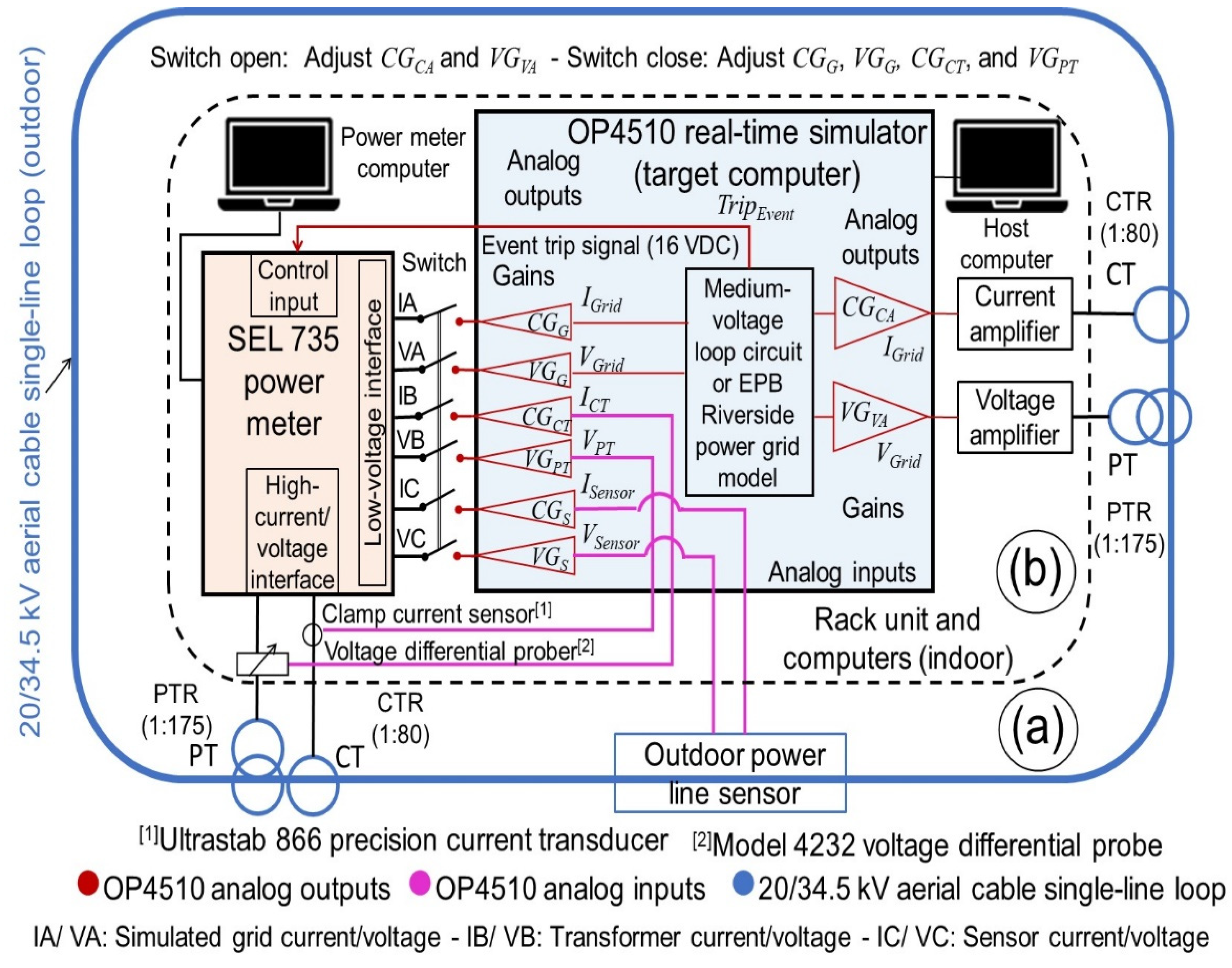
Figure 1 shows a diagram of the medium-voltage OPLST. The area outside the dashed line (Figure 1a) shows the 20/34.5 kV aerial cable loop with the PTs/CTs and the OPLS. The area inside the dashed line (Figure 1b) shows the equipment installed in the rack unit (indoor), including an OP4510 real-time simulator, an SEL-735 power meter, and current/voltage amplifiers. The OP4510 real-time simulator was connected to a host computer to run the tests, and the SEL-735 power meter was connected to another computer to collect the events after running the tests. The analog inputs of the OP4510 real-time simulator were connected to the PT/CT and to the OPLS, and the analog outputs were connected to the power meter and voltage/current amplifiers (Figure 1b). The SEL-735 power meter was connected to the high-voltage/current interface and to the low-voltage interface. Figure 1b shows that by opening the switch of the low-voltage interface, the high-current/voltage interface was enabled, and it was used to adjust the gains of the amplifiers (CGCA and VGVA) for the real-time simulator. However, by closing the switch of the low-voltage interface, the high-current/voltage interface was disabled, and the low-voltage interface was used to adjust the gains of the simulated medium-voltage loop circuit or power grid (CGG, VGG) and PT/CT (VGPT, CGCT) for the real-time simulator. As shown in Figure 1b, the voltage (VGVA, VGG, VGPT, VGS) and current (CGCA, CGG, CGCT, CGS) gains for analog outputs were calculated to set the RT-LAB project in the OP4510 real-time simulator. The gains to connect the SEL-735 power meter were calculated using the voltage (750 V/V) and current (16.53 A/V) scaling factors of the low-voltage interface. The gains to connect the voltage/current amplifiers were calculated using the amplifier gains and PT/CT ratios that were wired between the amplifiers and the medium-voltage aerial cable loop. From the low-voltage interface of the power meter (Figure 1b), phase A measured the voltage/current of the simulated medium-voltage loop circuit or power grid, phase B measured the voltage/current of the PT/CT, and phase C measured the voltage/current of the OPLS. To record the phase A, B, and C voltage/current signals during the tests, the OP4510 real-time simulator generated a 16 VDC signal (Figure 1b) that allowed to trip the recording of the test events inside the SEL-735 power meter.
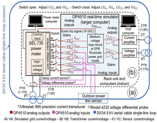
Figure 1.
Diagram of testbed with 20/34.5 kV aerial cable loop (a) and rack unit (b).
3.2. Voltage and Current Gains for the Real-Time Simulator
In the medium-voltage OPLST, the OP4510 real-time simulator (Figure 1b) was the main interconnection used to adapt the voltage and current signals from all devices. The voltage and current gains were calculated for the low-voltage interface of the SEL-735 power meter and the voltage/current amplifiers. The gains of the amplifiers, power grid, and PT/CT for the OP4510 real-time simulator were calculated. The voltage and current gains were calculated and then adjusted using the OP4510 real-time simulator and SEL-735 power meter. Table 2 shows the voltage and current gains of the OP4510 real-time simulator.
Table 2.
Voltage and current gains for the OP4510 real-time simulator.
3.3. Calculation of Voltage and Current Gains for Amplifiers at the Real-Time Simulator
The voltage and current amplifiers used in OPLST are the AE TECHRON Model 7228 [19]. These linear amplifiers can be used as single units or connected in series or parallel to increase the voltage and current outputs, respectively. Here, these amplifiers were used as single units by connecting one as a voltage-to-current amplifier and another as a voltage amplifier. The manufacturer default voltage and current gains of these amplifiers is 20 v/v and 5 A/V, respectively [19]. However, these gains were set by the gain control knob that can change the gain from 0% to 100% [19]. The voltage and current gains were set at approximately 20 v/v and 0.11 A/V, respectively. The voltage (VGVA) and current (CGCA) gains of the amplifiers for the OP4510 real-time simulator were calculated by using Equations (11) and (12), respectively.
where the VGVA is the voltage gain of the voltage amplifier for the OP4510 real-time simulator in volts/volt, GVA is the selected gain of the voltage amplifier in volts/volt, and PTRL is the ratio of PT connected between the voltage amplifier and medium-voltage aerial cable loop.
where the CGCA is the current gain of the current amplifier for the OP4510 real-time simulator in volts/amp, GCA is the selected gain of the current amplifier in amps/volt, and CTRL is the ratio of CT connected between the current amplifier and medium-voltage aerial cable loop.
3.4. Calculation of Voltage and Current Gains for Power Meter at the Real Time Simulator
In the OPLST (Figure 1), the SEL-735 power meter measured the voltage and current signals, and the OP4510 real-time simulator was the main interface between the SEL-735 power meter and the testbed devices. Therefore, the voltage/current gains for the OP4510 real-time simulator were calculated based on Table 2. The voltage and current gains of the simulated medium-voltage loop circuit or power grid for the OP4510 real-time simulator were calculated by Equations (13) and (14), respectively.
where the VGG is the voltage gain of the simulated medium-voltage loop circuit or power grid for the OP4510 real-time simulator in volts/volt, VSFM is the voltage scaling factor of the SEL-735 power meter in volts/volt, and PTRM is the PT ratio set in the SEL-735 power meter.
where the CGG is the current gain of the simulated medium-voltage loop circuit or power grid for the OP4510 real-time simulator in volts/amp, CSFM is the current scaling factor of the SEL-735 power meter in amps/volt, and CTRM is the CT ratio set in the SEL-735 power meter.
The voltage and current gains of the PT/CT for the OP4510 real-time simulator were calculated to connect the PT/CT signals at the low-voltage interface of the SEL-735 power meter. Therefore, a differential voltage probe and clamp current sensor were used to collect the PT/CT signals with the OP4510 real-time simulator (Figure 1b). For the PT connected to the SEL-735 power meter (Figure 1b), the voltage signal was collected using a Model 4232 differential voltage probe [20] that had a voltage scaling factor of 100 V/V. The voltage gain of the PT for the OP4510 real-time simulator is given by Equation (15).
where the VGPT is the voltage gain of the PT for the OP4510 real-time simulator, VSFDP is the voltage scaling factor of the Model 4232 voltage differential probe in volts/volt, and VSFM is the voltage scaling factor of the SEL-735 power meter in volts/volt.
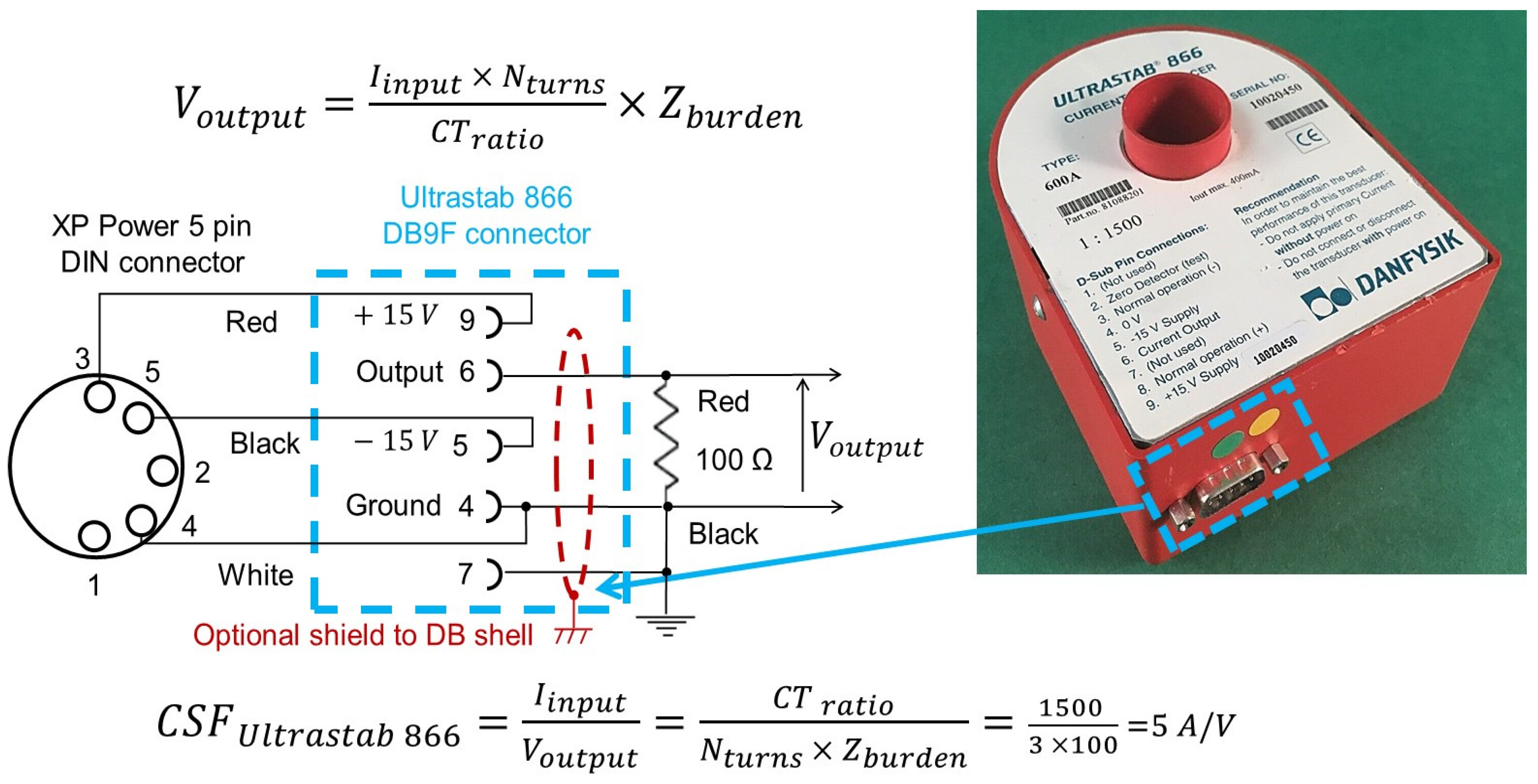
For the CT connected to the SEL-735 power meter (Figure 1b), the current signal was collected with an Ultrastab 866 precision current transducer [21] with a current transfer ratio of 1500:1, three turns of primary cable, and a burden external resistor impedance of 100 Ω. Figure 2 shows the circuit of the Ultrastab 866 precision current transducer.

Figure 2.
Circuit of the Ultrastab 866 precision current transducer.
From Figure 2 and Equations (16) and (17), the current scaling factor of the Ultrastab 866 precision current transducer (CSFU866) was determined to be 5 A/V.
where Voutput is the output voltage in volts, Iinput is the input current in amps, Nturns is the number of turns of primary cable, CTratio is the current transfer ratio of the Ultrastab 866 precision current transducer (1500:1), CSFU866 is the current scaling factor of the Ultrastab 866 precision current transducer in amps/volt, and Zburden is the burden external resistor impedance in ohms.
Because the CT was connected to the Ultrastab 866 precision current transducer, the current gain of the CT for the OP4510 real-time simulator was calculated using Equation (18).
where the CGCT is the current gain of the CT for the OP4510 real-time simulator, CSFU866 is the current scaling factor of the Ultrastab 866 precision current transducer in amps/volt, and CSFM is the current scaling factor of the SEL-735 power meter in amps/volt.
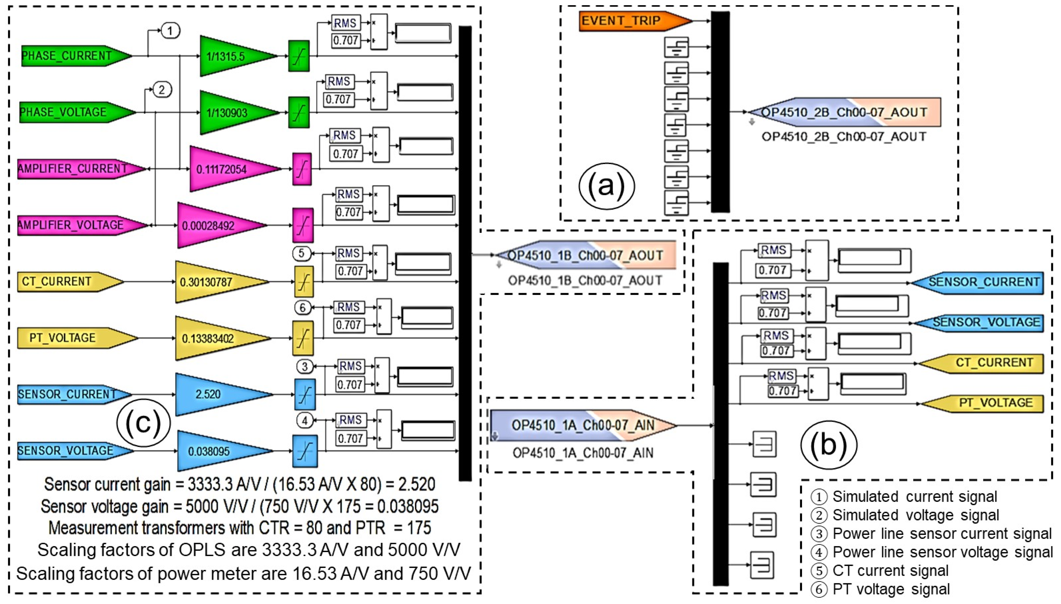
The voltage and current gains of the OPLS for the OP4510 real-time simulator were calculated using Equations (19) and (20), respectively. This calculation process required the voltage (5000 V/V) and current (3333.3 A/V) scaling factors of the OPLS, voltage (750 V/V) and current (16.53 A/V) scaling factors of the SEL-735 power meter, and the PT (175:1) and CT (80:1) ratios set in the SEL-735 power meter.
where the VGS is the voltage gain of the OPLS for the OP4510 real-time simulator, VSFS is the voltage scaling factor of the OPLS in volts/volt, VSFM is the voltage scaling factor of the SEL-735 power meter in volts/volt, and PTRM is the PT ratio set in the SEL-735 power meter.
where the CGS is the current gain of the OPLS for the OP4510 real-time simulator, CSFS is the current scaling factor of the OPLS in amps/volt, CSFM is the current scaling factor of the SEL-735 power meter in amps/volt, and CTRM is the CT ratio set in the SEL-735 power meter.
3.5. Adjustment of Voltage and Current Gains
The calculated voltage and current gains for the OP4510 real-time simulator were adjusted by creating an RT-LAB project that simulated a medium-voltage loop circuit, as shown in Figure 3.
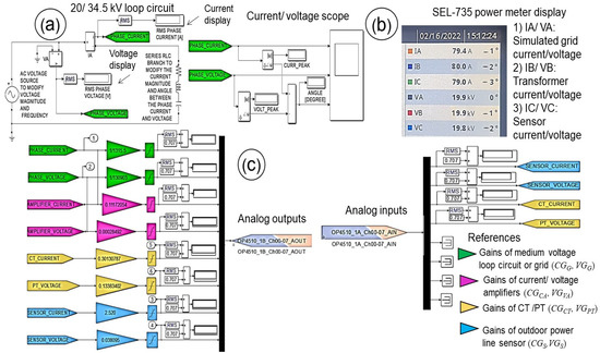
Figure 3.
Medium-voltage loop circuit (a), SEL-735 power meter display (b), and gains (c).
This circuit was formed by a sinusoidal source and an impedance in series (Figure 3a) that simulated the line-to-ground voltage of 19.9 kV and line current of 80 A. The adjusting process of the gains for the OP4510 real-time simulator was based on running a simulation test of the medium-voltage loop circuit and comparing the measurements with those on the display of the SEL-735 power meter (Figure 3b). The gains calculated using Equations (11)–(15) and (18) were initially set in the model (Figure 3c). Then, these values were adjusted to match the conditions shown in Table 3.
Table 3.
Adjustment of voltage and current gains for the OP4510 real-time simulator.
The amplifier gains (VGVA and CGCA) for the OP4510 real-time simulator were adjusted by using the measured the voltage/current from the PT/CT of phase B at the high-voltage/current interface in the SEL-735 power meter as a reference that represented the real voltage/current from the outdoor medium-voltage aerial cable loop in the OPLST. These gains were adjusted using Equation (21).
where G′ADJ are the adjusted voltage and current gains of the amplifiers for the OP4510 real-time simulator in volts/volt and volts/amp, respectively; G′CALC are the calculated voltage/current gains of the amplifiers from Equations (11) and (12), respectively; MH are the measured phase-B voltage and current values that were collected by using the high-voltage/current interface in volts and amps; and SGRID are the simulated phase voltage/current values that were measured from the voltage and current displays of the 20/34.5 kV loop circuit in volts and amps, respectively (Figure 3a).
Additionally, the gains of the simulated grid (VGG and CGG) and PT/CT (VGPT and CGCT) for the OP4510 real-time simulator were adjusted by using the measured the voltage/current from the phase-B PT/CT at the high-voltage/current interface in the SEL-735 power meter as a reference. These gains were adjusted using Equation (22).
where GADJ are the adjusted voltage/current gains of the simulated grid (in volts/volt and volts/amp, respectively) and PT/CT (unitless) for the OP4510 real-time simulator; GCALC are the calculated voltage/current gains from Equations (13)–(15) and (18); MH are the measured phase B voltage/current that were collected using the high-voltage/current interface in volts and amps, respectively; and ML are the measured phase A or B voltage/current that were collected by using the low-voltage interface in volts and amps, respectively, based on the conditions in Table 3.
In this gain adjustment process for the OP4510 real-time simulator, when the low-voltage interface was connected at the SEL-735 power meter, the measurements from the high-voltage/current interface were not available from the SEL-735 power meter’s display. Then, during the simulation of the 20/34.5 kV loop circuit tests (Figure 3a), the low-voltage interface of the SEL-735 power meter was connected and disconnected to adjust the voltage/current gains with Equations (21) and (22), based on the conditions shown in Table 3.
3.6. Medium-Voltage Outdoor Power Line Sensor Testbed
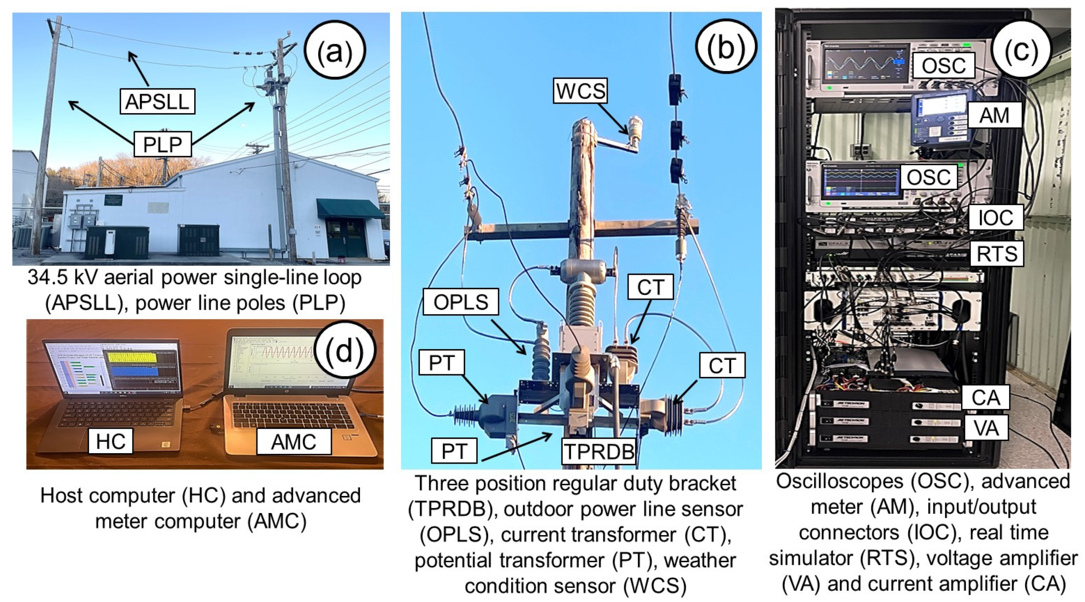
The 20/34.5 kV OPLST (Figure 4a,b) was located at the DECC laboratory at ORNL. Figure 4 shows the medium-voltage aerial cable loop, power line poles, sensors (including others not mentioned in this report), control rack unit, and computers. The PTs were ABB VOG-20B voltage transformers, with a ratio of 20,125 V/115 V, or a potential transformer ratio (PTR) of 175, and the CTs were ABB KOR-20ER current transformers with a ratio of 400 A:5 A or with a current transformer ratio (CTR) of 80. A mounting bracket (Figure 4b) allowed for mounting the OPLS and PTs/CTs. Inside the DECC lab, the rack unit (Figure 4c) housed the power meter, simulator, and amplifiers (Techron Model 7228). The OPLST accurately reproduced the current and voltage waveforms under most conditions but within limits because of the nature of the transformers operated under reverse conditions. The current amplifier that fed the CT in the OPLST (Figure 1) could not generate currents greater than 80 A in the aerial cable single loop circuit without introducing distortions caused by core nonlinearities. Thus, high current faults could not be directly generated by the OPLST. Additionally, the PT used to increase the voltage had an intrinsic resonance at roughly 1500 Hz, which became evident during events with abrupt voltage changes by a ringing of the applied voltage. The CT and PT used as reference sensors were extensively tested during the commissioning of the OPLST and found to be very accurate to beyond the 100th harmonic.
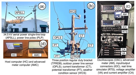
Figure 4.
Medium-voltage aerial cable loop (a), power line pole with sensors (b), rack unit (c), and computers (d).
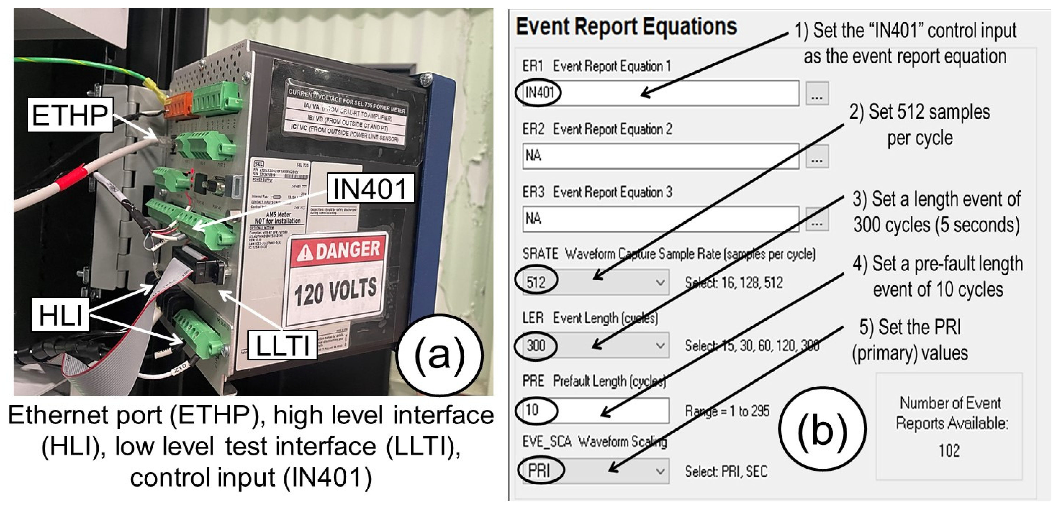
In the rack unit, an advanced meter computer (Figure 4d) was used to set the power meter and to collect the transient events as COMTRADE files after running the tests. In the power meter, phase A was configured to measure the voltage/current of the simulated circuit or power grid, phase B measured the voltage/current signals of the PT/CT, and phase C measured the voltage/current signals of the OPLS. Figure 5a shows the rear side of the power meter on the rack unit. In the power meter, the low-voltage interface measured the voltage and current signals via a DB-25 connector that had a voltage scaling factor of 750 v/v and a current scaling factor of 16.53 A/V. These voltage and current scaling factors were used to integrate the signals from the power grid simulation, PT/CT, and OPLS with the power meter through the simulator using the Equations (13)–(15) and (18)–(20). In Figure 5b, the “Event Report Equations” setting for the power meter is shown. The power meter could save the voltage/current signal events as COMTRADE files. The power meter was set using AcSELerator Quickset software (version 7.1.4.0), and the event was triggered by the control input IN401 that was controlled with a signal of 16 VDC (Pickup 15–30 VDC) that was generated by the simulator. In the power meter, the waveform capture sample rate was set to 512 samples per cycle, and the event length was set to 300 cycles to record the test events for 5 s. The power meter had a color touchscreen that facilitated observation of the sinusoidal and phasor diagrams of voltage/current signals with 256 samples per cycle [22]. During the tests, the signals could be supervised from the display of the power meter practically in real time.
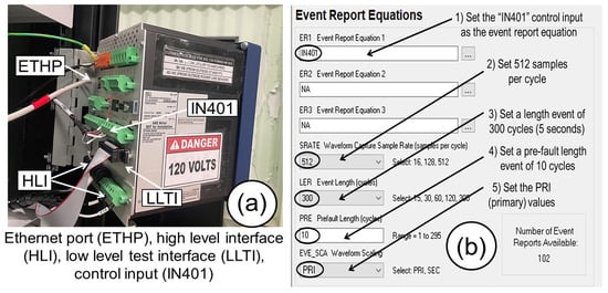
Figure 5.
Power meter rear side (a) and event report settings (b).
4. Experimental Model
4.1. Single Line Diagram
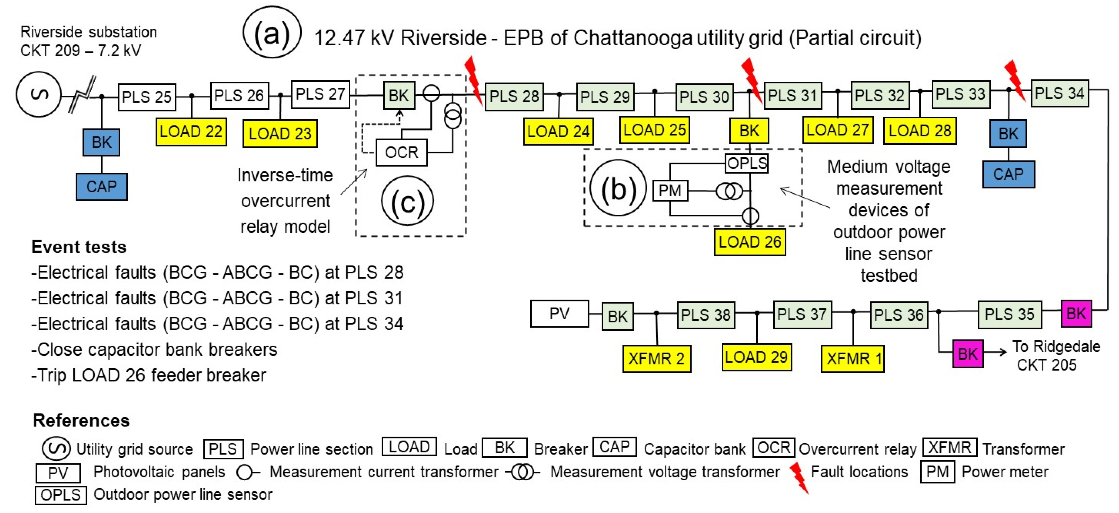
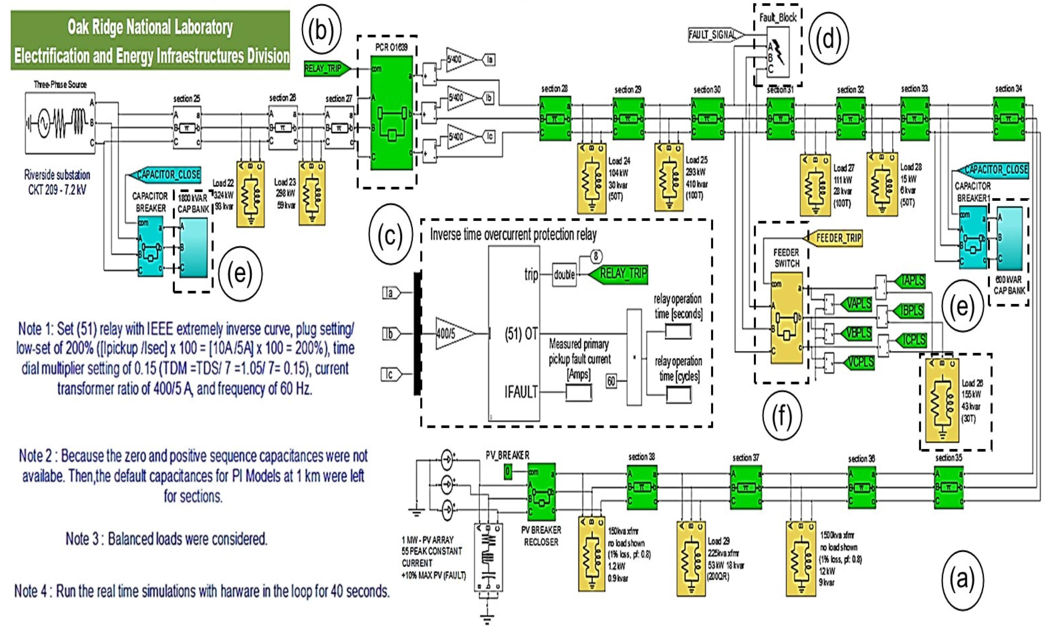
This study simulated a power grid model based on a utility circuit at the Riverside EPB of Chattanooga. The simulation circuit was created with MATLAB/Simulink software and was integrated into an RT-LAB project to run with the OP4510 real-time simulator at the OPLST. Figure 6 shows the single line diagram.
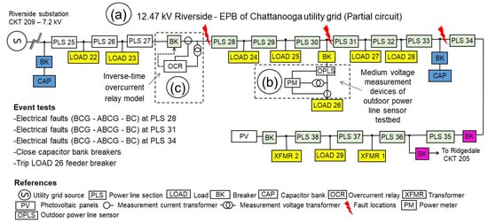
Figure 6.
Single line diagram of 12.47 kV Riverside utility grid partial circuit (a), outdoor power line sensor location (b) and inverse-time overcurrent relay site (c).
This network configuration is a radial power system (7.2 kV phase-to-ground voltage) that is fed by a three-phase source with a Wye-grounded configuration (Figure 7a). At load 26 (Figure 6b), the voltage and current were measured by the OPLS and PT/CT at the load feeder. The overcurrent relay (Figure 6c) was located between power line sections 27 (PLS 27) and 28 (PLS 28) to clear the electrical faults along the power lines. This experimental model performed various tests such as the line to line ground (LLG), line to line (LL), and three-line to ground (3LG) electrical faults; capacitor bank operation; and load 26 fuse switch events.

Figure 7.
Three-line diagram of power grid circuit (a), relay breaker (b), inverse-time overcurrent relay (c), fault block (d), capacitor banks (e), and feeder switch (f).
4.2. RT-LAB Project
Figure 7 shows the three-line circuit in the RT-LAB project, including a relay breaker (Figure 7b), an inverse-time overcurrent relay (Figure 7c), a fault block (Figure 7d), capacitor banks (Figure 7e), and a feeder switch (Figure 7f). This power grid circuit included the utility source, power line sections, feeder loads, breakers, and capacitor banks.
Power line sections were simulated with a three-phase π-section line block. IntelliRupters were used in the EPB grid [8]; however, an inverse-time overcurrent relay MATLAB/Simulink model [23] was used in this study. The ratio of the CTs for the relay’s breaker was 400A:5A = 80. The inverse-time overcurrent relay model (Figure 7c) was set with a time dial setting of 1.05 s, current transformer ratio of 80, relay current pickup of 10 amps, and IEEE extremely inverse curve as shown in Equation (23):
where TR is the relay time in cycles, TDS is the time dial setting in seconds, Iprimary is the primary current in amps, CTR is the current transformer ratio, and Ip is the relay current pickup in amps.
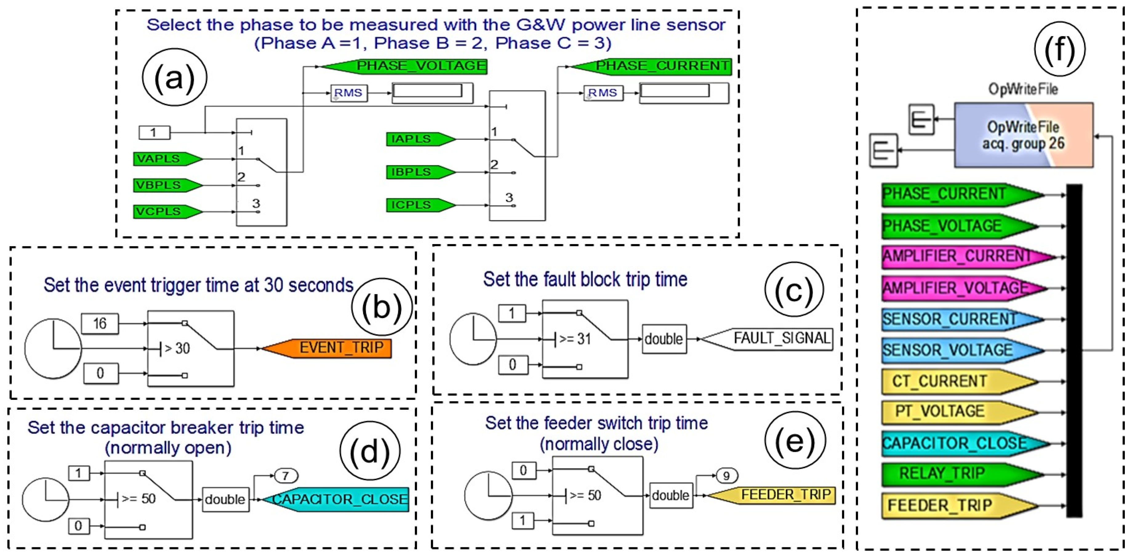
The inverse-time overcurrent relay allowed the opening of the breaker (Figure 7b) at the electrical fault currents. The grid simulation events were run to observe the prefault, fault, and postfault states for each test. The simulated grid test events included the effect of the electrical fault resistance, with the fault block (Figure 7d) set to an electrical fault resistance of 0.001 Ω. The OPLST was given by a medium-voltage aerial cable loop. Therefore, before running a test for the three-line diagram (Figure 7), the A, B, and C phases to be measured by the OPLS was selected from the phase-setting circuit (Figure 8a) by selecting 1, 2, or 3 for measuring the A, B, or C phase, respectively.
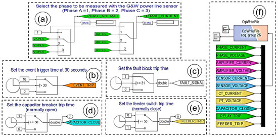
Figure 8.
Phase-setting circuit (a), event-trigger circuit (b), electrical fault circuit (c), capacitor bank circuit (d), feeder switch circuit (e), and OpWrite File block (f).
During the tests, the real-time simulations were run for 40 s, and the signal to record the test event with the power meter was set at 30 s for the event-trigger circuit (Figure 8b). To record the test event with the voltage/current signals before and after the transient events, the selected test scenario was tripped at 31 s, and the other test scenarios were set at 50 s. As shown in Figure 8, the electrical fault block circuit (Figure 8c) was set at 31 s, and the capacitor bank (Figure 8d) and feeder switch (Figure 8e) circuits were set at 50 s to run an electrical fault test by tripping the fault block (Figure 7d). The OpWrite File block (Figure 8f) allowed the collection of test results as MATLAB files. Additionally, the capacitor bank, relay breaker, and feeder switch states were collected. Figure 9 shows the interface circuits for the analog outputs and inputs of the simulator based on Figure 1b. The circuit for the event-trip output signal for the power meter is shown in Figure 9a. The interface circuit for the voltage and current signals of the OPLS and PT/CT are shown in Figure 9b. The analog outputs of the interface circuit for the gains of the simulator at the voltage/current amplifiers, PT/CT, and OPLS are shown in Figure 9c.
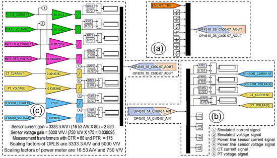
Figure 9.
Event-trip output signal (a), OPLS and PT/CT input signals (b), and amplifier/PT/CT and OPLS output signals (c).
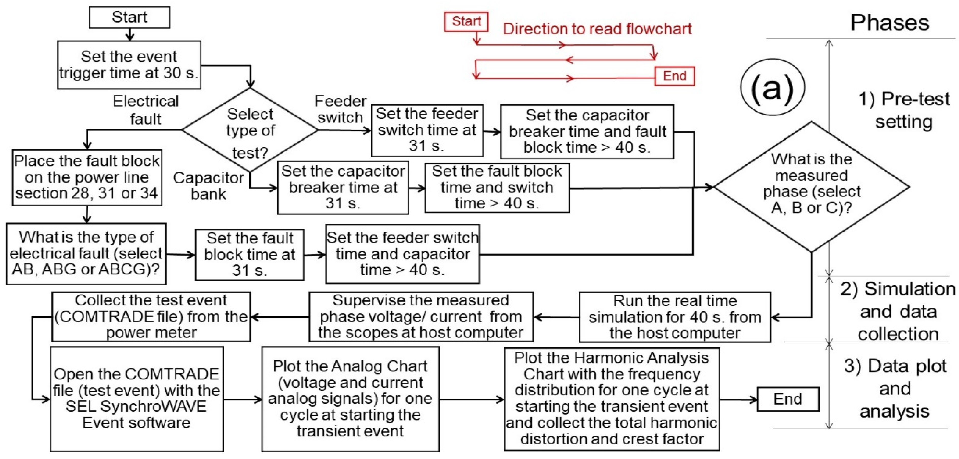
4.3. Experimental Model Flowchart
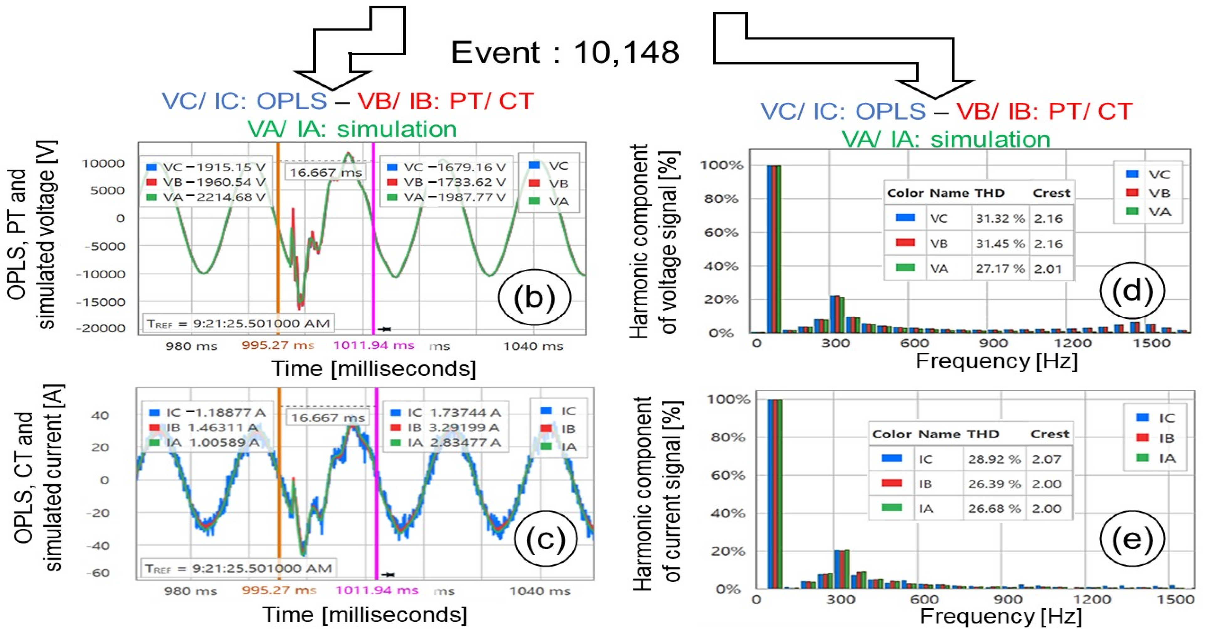
The flowchart for the experimental model (Figure 10a) is based on the (1) pretest setting, (2) simulation and data collection, and (3) data plot and analysis. The tests were recorded by the power meter at 30 s (Figure 8b) and the start of the simulations, and the recorded data for all tests included 300 cycles (5 s). The data from the events were analyzed around the time when the electrical faults happened (i.e., when the breakers of feeders and capacitor banks were operated). This process allowed the observation of the behavior of the phase voltage/current signals (Figure 10b,c) and harmonic analysis (Figure 10d,e) at transient events to compare the performance of the OPLS with that of the PT/CT.
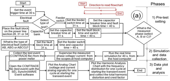
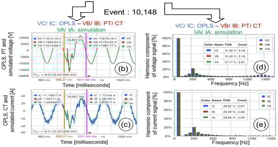
Figure 10.
Flowchart (a) to run the tests with the outdoor power line sensor versus CT/PT with the phase voltage (b) and current (c) signals, and voltage (d) and current (e) harmonic components.
In the experimental model (Figure 10a), initially, the event trigger circuit was set to record the test events in the power meter at 30 s. Then, the type of the test event was selected (electrical faults, capacitor bank, or feeder switch). If the electrical fault tests were selected, then the fault block was placed on the power line section 28, 31, or 34 (Figure 6), and the AB (phase A and B), ABG (phase A and B to ground), or ABCG (phases A, B, and C to ground) electrical faults were set on the fault block (Figure 7d). The fault block time was set at 31 s (Figure 8c) to generate the electrical fault, and the feeder switch and capacitor time blocks (Figure 8d,e) were set at 50 s to not trip these scenarios during the simulation. If the capacitor bank test was selected, then the capacitor breaker time was set at 31 s (Figure 8d), and the electrical fault and feeder switch time blocks (Figure 8c,e) were set at 50 s to not trip these scenarios at the tests. Finally, if the feeder switch test was selected, then the feeder switch breaker time was set at 31 s (Figure 8e), and the electrical fault and capacitor bank switch time blocks (Figure 8c,d) were set at 50 s to not trip these scenarios at the tests.
As shown in Figure 10a, once the electrical fault, capacitor bank, or feeder switch time blocks were set, the A, B, or C phase to be measured in the simulated power grid circuit (Figure 7) was selected using the phase-setting circuit (Figure 8a). The real-time simulation tests were then run and observed using the voltage/current scopes on the host computer; the test event data were collected by the power meter to plot signals in the time domain (Figure 10b,c) and their harmonic components in the frequency domain (Figure 10d,e).
5. Results and Discussion
5.1. Total Harmonic Distortion and Crest Factor
The numerical results of the tests given by the total harmonic distortion and crest factor values for each voltage and current phase (A, B, and C) were collected in a published report [24]. The measured total harmonic distortion and crest factors for the voltage and current signals of the OPLS and PT/CT were collected from the frequency plots and listed in Table 4 [24]. The tests were grouped by the power grid measured phase (A, B, or C). The tests were named according the load and type of event (electrical faults and location, capacitor bank operation, or feeder switch). The total harmonic distortion and crest factors for each event and for each voltage and current phase A, B, and C are plotted in Figure 11 and Figure 12.
Table 4.
Total harmonic distortion and crest factor of phases A, B, and C for the OPLS vs. the PT/CT.
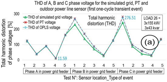
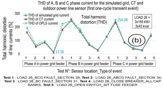
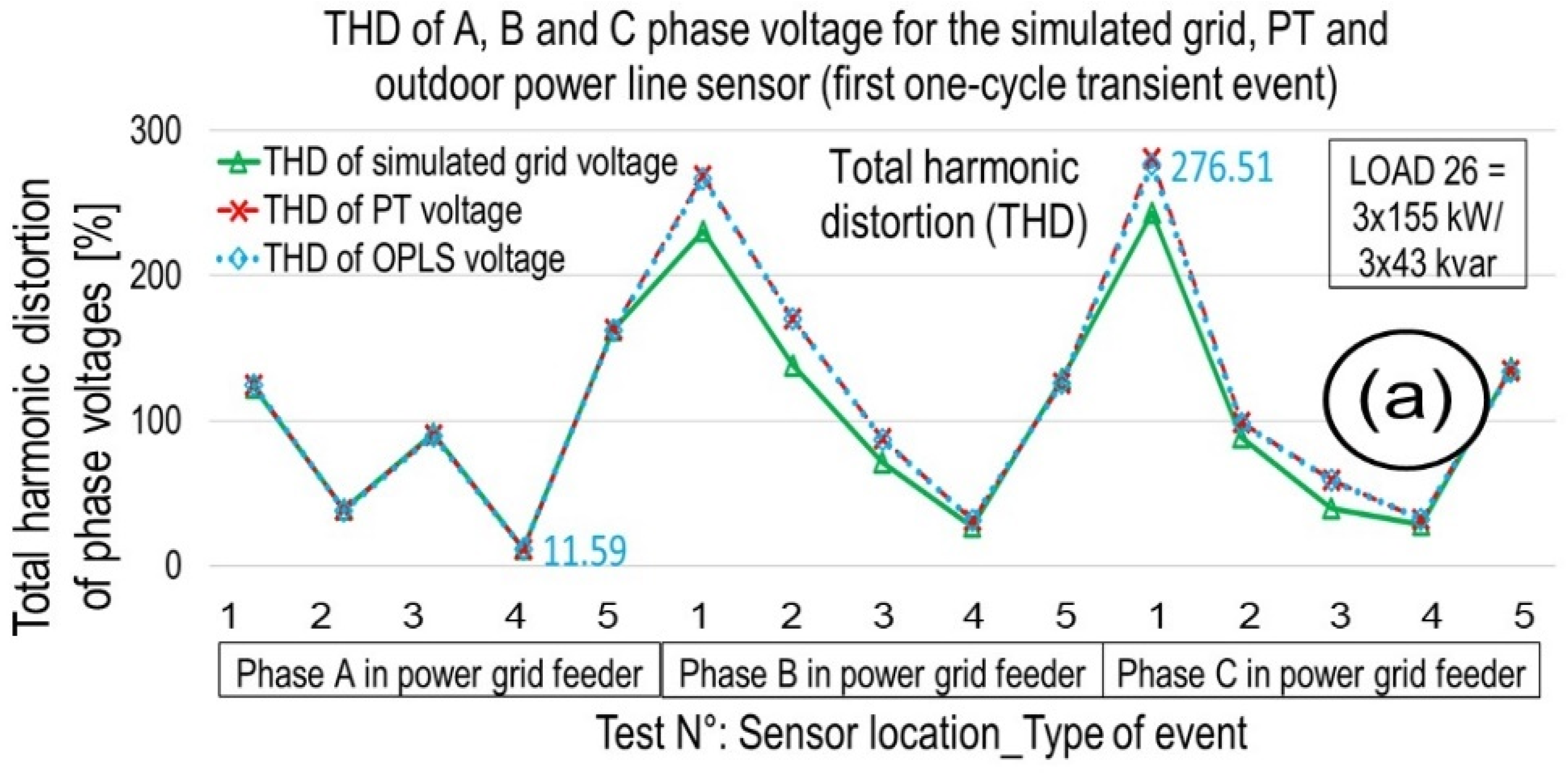
Figure 11.
Total harmonic distortion of phases A, B, and C voltage (a) and current (b) signals for the simulated grid, PT/CT, and outdoor power line sensor.
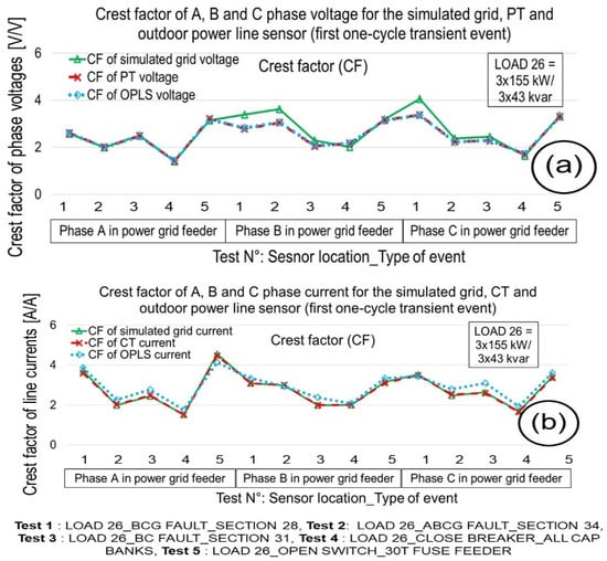
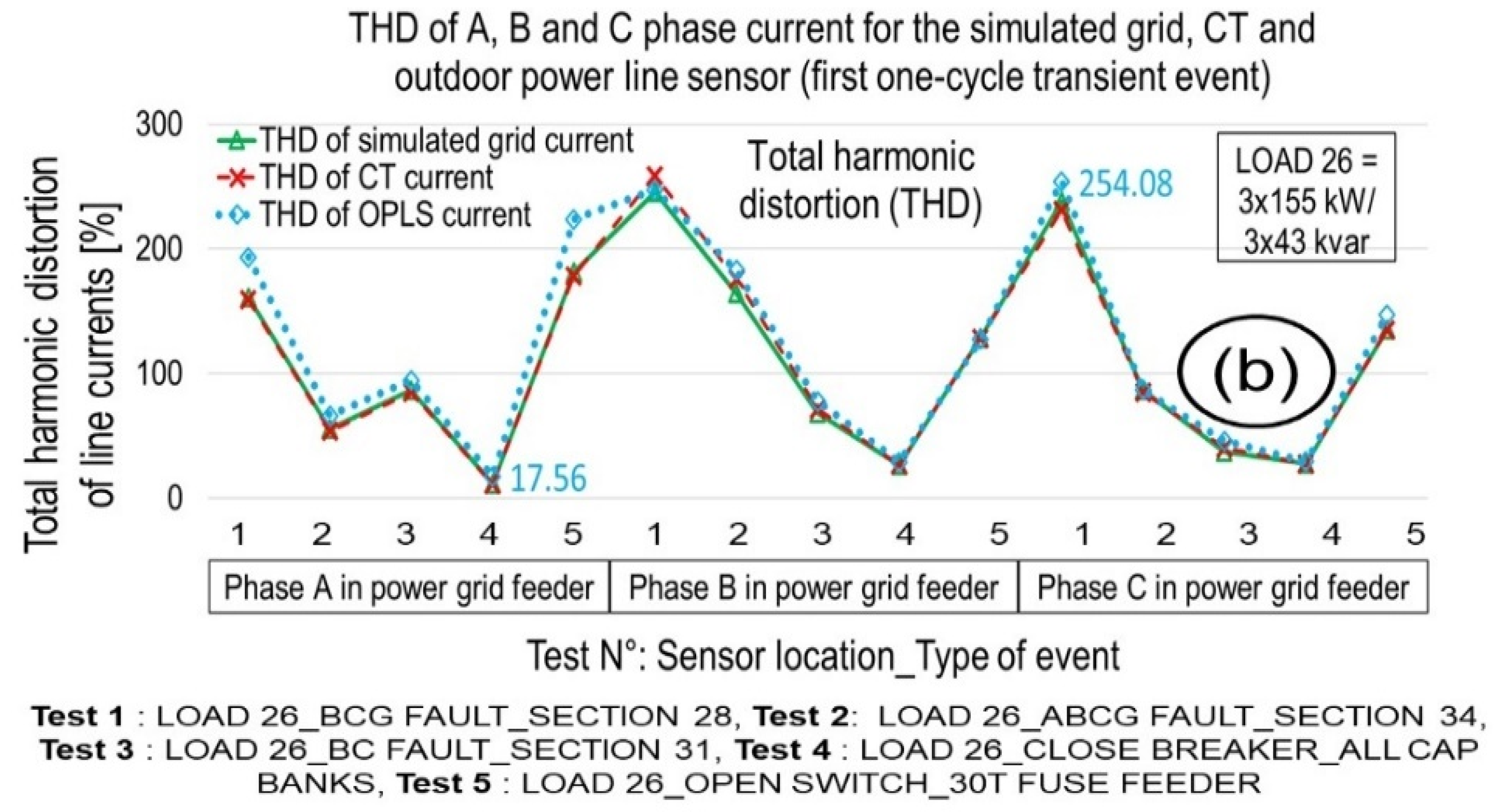
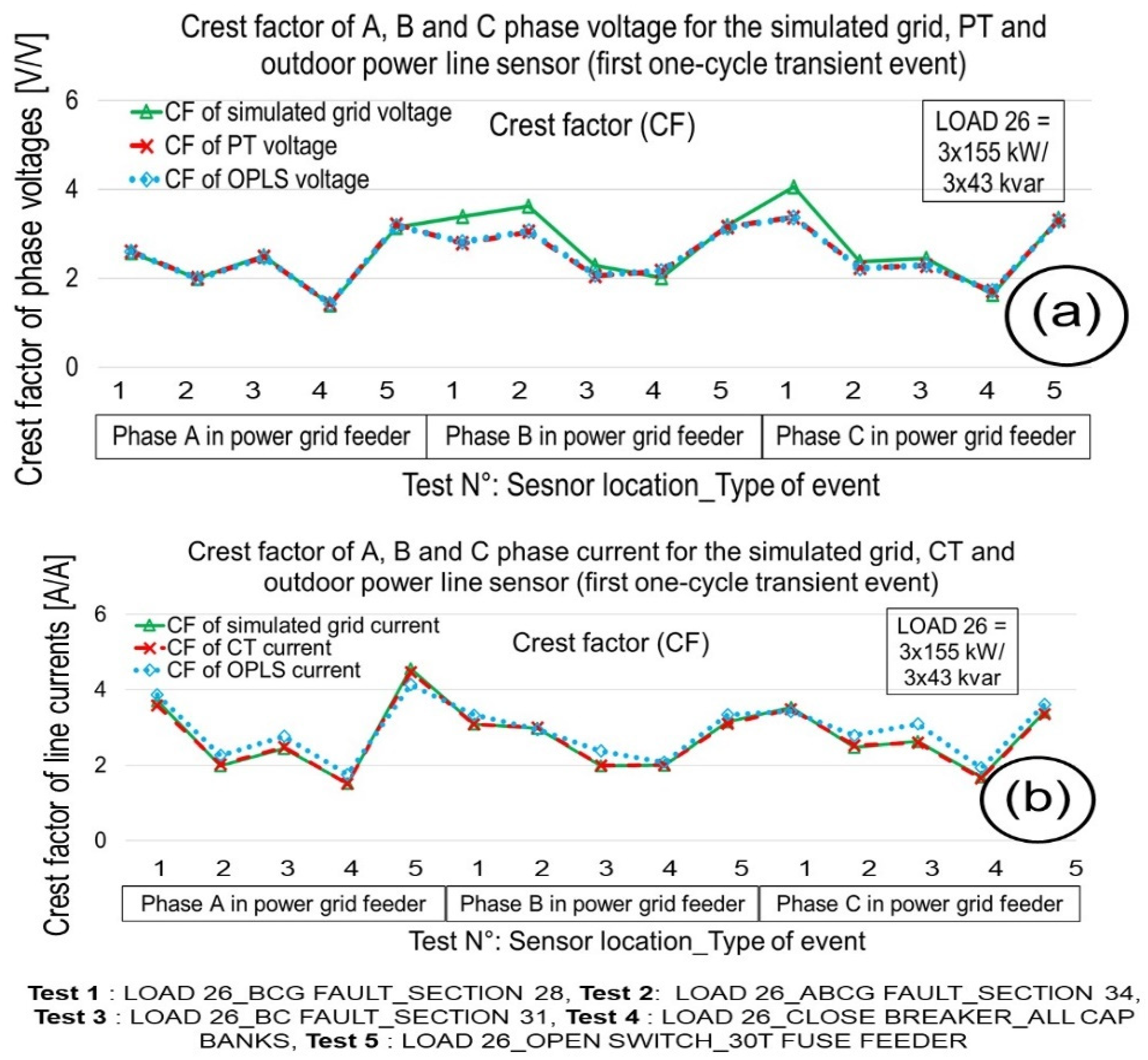
Figure 12.
Crest factor of phase A, B, and C voltage (a) and current (b) signals for the simulated grid, PT/CT, and outdoor power line sensor.
These figures indicate reasonable agreement between the simulated signals, PT and CT signals, and OPLS signals. In general, the observed THDV of the PT and OPLS were in very good agreement, but for some events, they were substantially higher than the measured simulation signals input to the voltage amplifier. This effect is attributed to a resonance in the neighborhood of 1500 Hz for the excitation PT in especially fast transients that was followed by both the reference PT and the OPLS. Such resonance was not observed in the CT; however, the relative background noise of the OPLS was substantially higher (Figure 10c) because the OPLS had a current range that extends to >20 kA, far exceeding the excitation levels of 20–30 A of the present study. Consequently, the THDI and CFI of the OPLS were slightly higher than those of the simulation and CT sensor currents. In Figure 11 and Figure 12, the measured total harmonic distortion and crest factor values correspond to the first one-cycle (~16.6 ms) transient event of the simulated tests. The total harmonic distortion of the voltage and current signals for the OPLS varied from 11.59% to 276.51% (Figure 11a) and from 17.56% to 254.08% (Figure 11b), respectively. The minimum and maximum total harmonic distortion corresponded to the closed capacitor bank test and the BCG electrical fault test, respectively. In Figure 11, total harmonic distortions (THDV or THDI) greater than 0% indicate that the numerator is greater than the denominator in Equations (3) and (4). Then, the contribution of the of the harmonic components with respect to the fundamental frequency (60 Hz) are available in the measured signals. A pure signal based on the fundamental (60 Hz) with low harmonic components resulted in measured total harmonic distortions (THDV or THDI) near 0%.
5.2. Total Harmonic Distortion and Crest Factor Percentage Errors
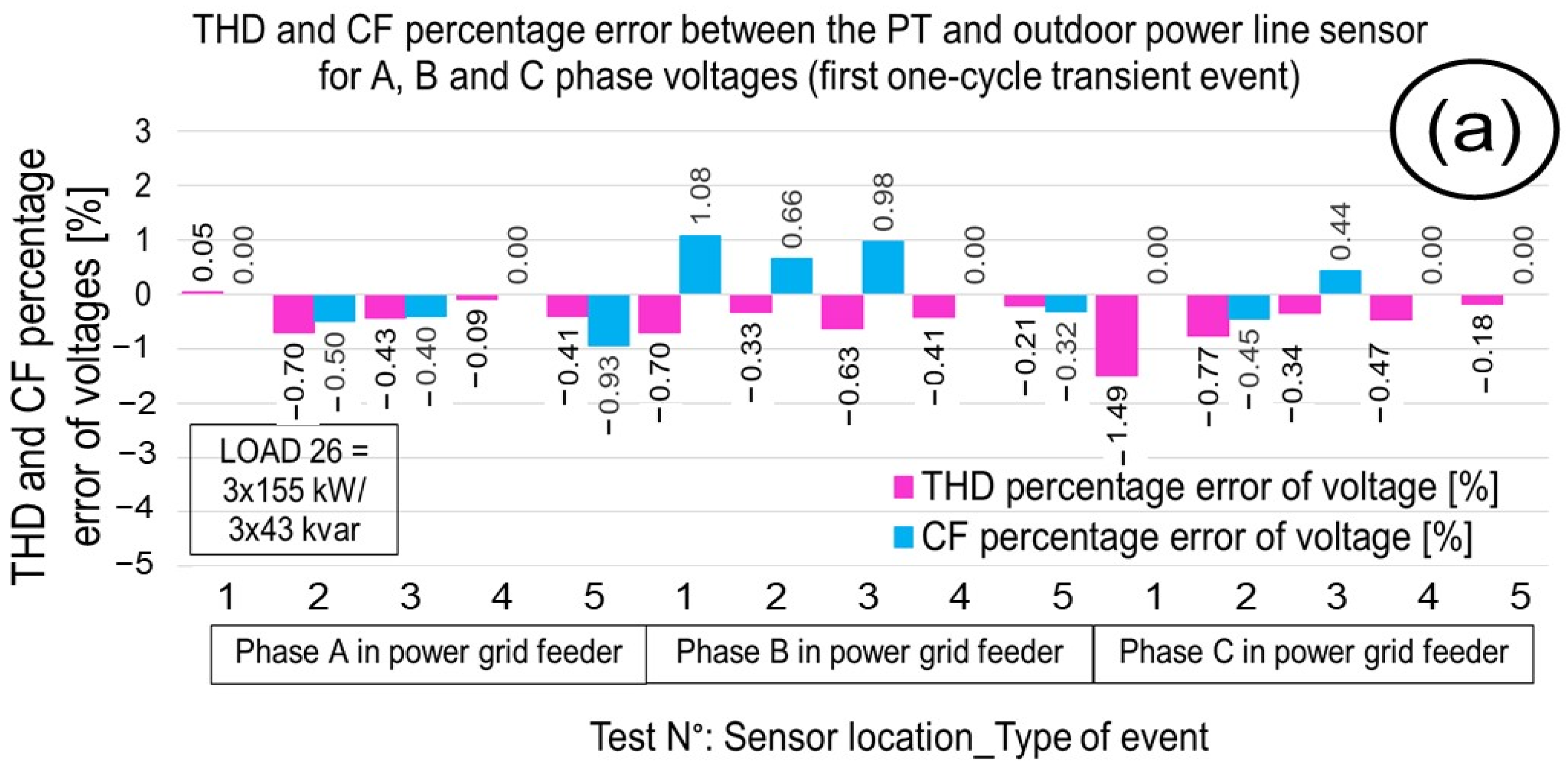
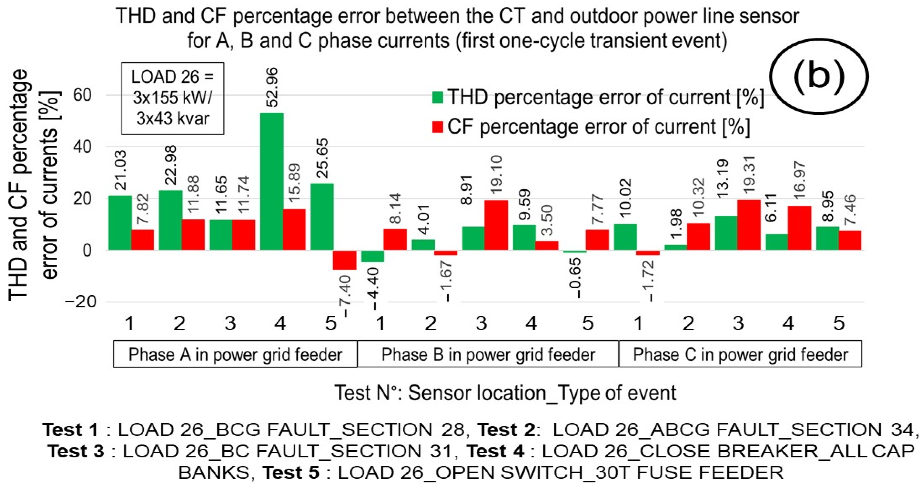
The total harmonic distortion and crest factor percentage errors of the test events (electrical faults, capacitor bank operators, and load feeder switch) for the measured phase A, B, and C voltage (Figure 13a) and current (Figure 13b) signals in the power grid feeder were plotted, comparing the performance of the OPLS with that of the PT/CT. The percentage errors for the total harmonic distortion and crest factor values correspond to the first one-cycle (~16.6 ms) transient event of the simulated tests. The total harmonic distortion and crest factor percentage errors were calculated using Equations (7)–(10).

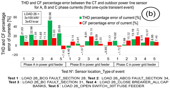
Figure 13.
Total harmonic distortion and crest factor percentage error of phase A, B, and C for the voltage (a) and current (b) signals between the OPLS and the PT/CT.
To calculate the percentage errors, the signals from the PT/CT and the OPLS power line sensor were considered as the expected and measured values, respectively. In Figure 13a, the pink bars are the total harmonic distortion (0.05% to −1.49%) of the voltage signals, and the blue bars are the crest factor (1.08% to −0.93%) percentage errors of the voltage signals. In Figure 13b, the green bars are the total harmonic distortion (52.96% to −4.40%) percentage errors of the current signals, and the red bars represent the crest factor (19.31% to −7.4%) percentage errors of the current signals.
5.3. Voltage and Current Signals from Test Events
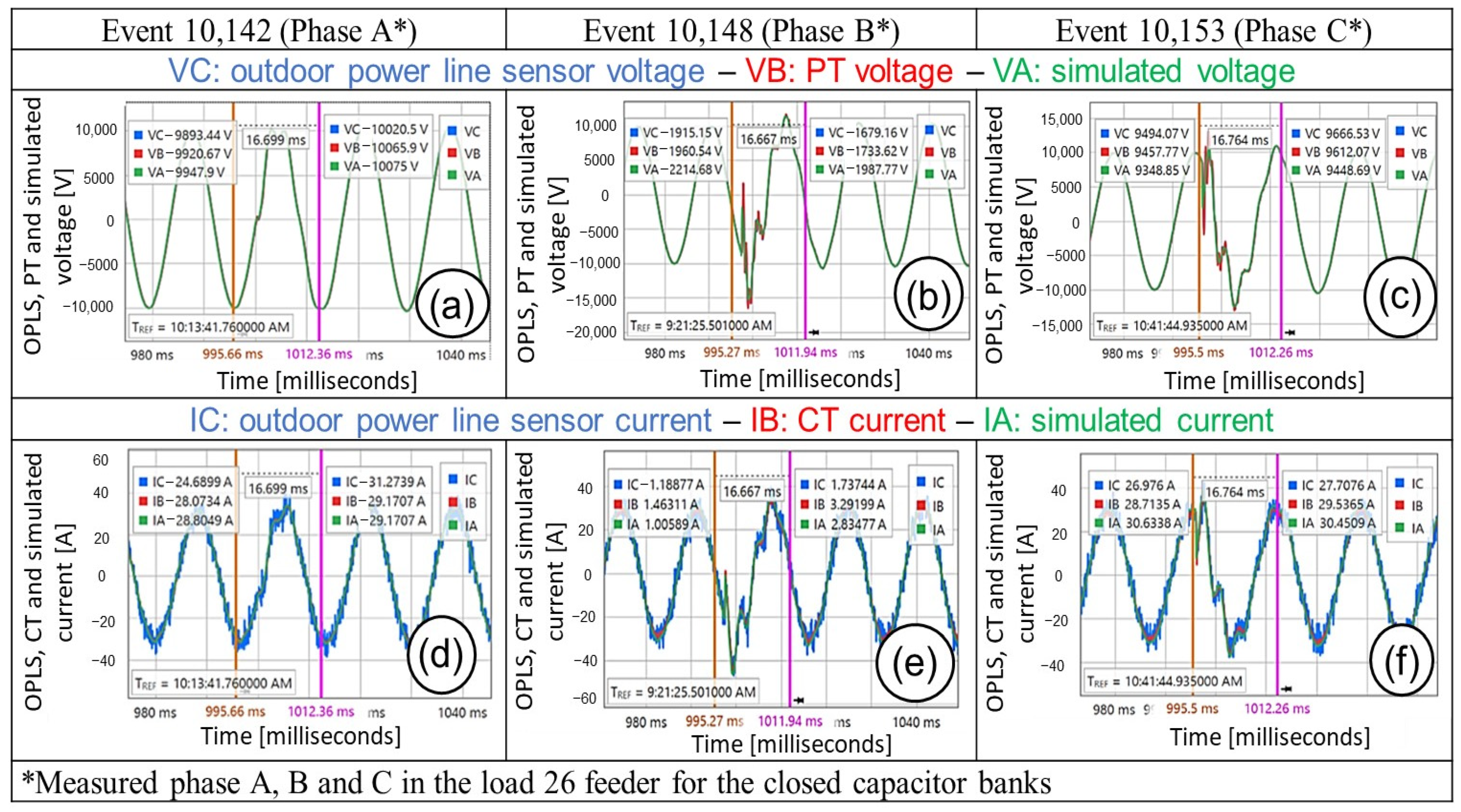
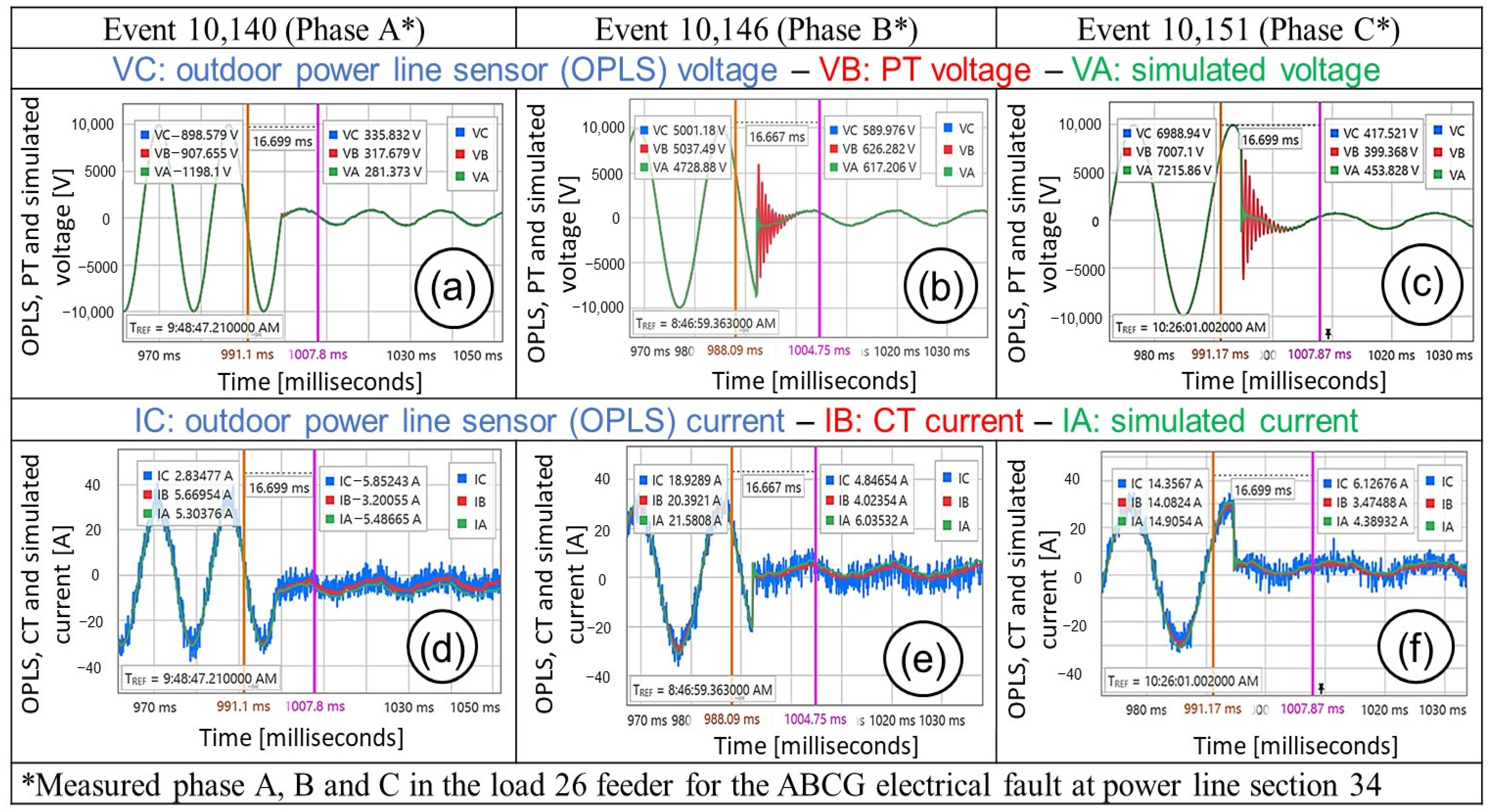
In the electrical fault events, the phase voltage and current signals were generated, and different transient events were consequently plotted. The test events (electrical faults, capacitor bank operation, and load feeder switch) were run for phases A, B, and C. Because the test events were triggered at the same time, the measured phase A, B, and C current and voltage signals were generated at different angles based on a three-phase system definition [25], which had a phase difference of 120 degrees. Figure 14 and Figure 15 show the voltage and current of phase A (a, d), B (b, e), and C (c, f) for the outdoor power line sensor, PT/CT, and simulated power grid when the capacitor banks were closed and when an ABCG electrical fault in the main feeder was set, respectively.
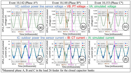
Figure 14.
Voltage and current of phases A (a,d), B (b,e), and C (c,f) for the outdoor power line sensor, PT/CT, and simulated power grid at the load 26 feeder when the capacitor banks are closed.
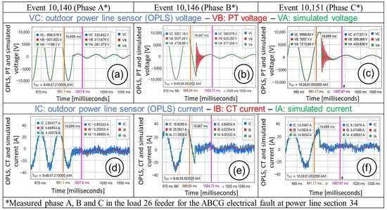
Figure 15.
Voltage and current of phase A (a,d), B (b,e), and C (c,f) for the outdoor power line sensor, PT/CT, and simulated power grid at load 26 feeder and ABCG electrical fault in power line section 34 (PLS 34).
In the capacitor bank operation tests (Events 10142, 10148, and 10153), the voltage and current signals were observed by plotting the first one-cycle (~16.6 ms) transient event at the measured phases A, B, and C. These events represented the time when the capacitor banks along the power line sections were closed in the simulated power grid (Figure 6). The voltage and current signals at the load feeder (Figure 6b) were measured at the medium-voltage OPLST. The measured voltage (Figure 14a–c) and current (Figure 14d–f) signals for phases A, B, and C were compared for the OPLS vs. the PT/CT. In Figure 14, the blue, red, and green lines are the voltage/current signals for the OPLS, PT/CT, and simulated power grid, respectively. For the first one-cycle (~16.6 ms) transient event, the behaviors of the voltage and current signals for the OPLS and PT/CT were similar for the same measured phase.
In the ABCG electrical fault event tests (Events 10140, 10146, and 10151), the voltage signals were plotted for the first one-cycle (~16.6 ms) transient event for phase A, B, and C. These events represented the time when the electrical fault happened at power line section 34 (PLS 34) in the simulated power grid (Figure 6). Then, the voltage and current signals at the load feeder (Figure 6b) were generated at the medium-voltage OPLST. The effect of the ABCG electrical fault at the power line produced the line currents and voltages decreased on the load feeder (Figure 15). The measured voltage (Figure 15a–c) and current (Figure 15d–f) signals for phase A, B, and C were compared with the OPLS vs. the PT/CT. In Figure 15, the blue, red, and green lines are the voltage/current signals for the OPLS, PT/CT, and simulated power grid, respectively. For the first one-cycle (~16.6 ms) transient event, the behaviors of the voltage and current signals for the OPLS and PT/CT were similar for the same measured phase. In the first one-cycle (~16.6 ms) transient event, the voltage and current signals of phase A had a sinusoidal form (Figure 15a,d), whereas the voltage signals of phases B and C had a distortion (Figure 15b,c) that generated a ringing frequency for the OPLS and PT.
The capability of measuring current and voltage harmonics with power line sensors is very important. When harmonics are presented in the main voltage or line currents for permanent states (non-transient states), the power quality of the electrical grid can decrease. Another effect of the harmonics is to increase the current in transformers and the electrical grid with consequent rise in device temperature and power losses. For example, the third harmonic causes a sharp increase in the zero-sequence current and increases the current in the neutral conductors. A non-linear load connected to the electrical grid draws a current that is not necessarily sinusoidal, and therefore it generates harmonics. The voltage harmonics are mostly caused by current harmonics. However, if the source impedance of the voltage source is small, current harmonics will cause only small voltage harmonics. It is typically the case that voltage harmonics are indeed small compared to current harmonics. In the results, from Figure 11a,b, the behavior of the total harmonic distortion for the current and voltage signals had shown a similar behavior for the same phase and event test, observing a similar conduct for the current and voltage signals.
In this study, the proposed methodology was implemented in an OPLS testbed instead of a real grid. It is because electrical fault grid events are not likely to be run by an electrical utility for safety concerns and possible infrastructure damages in the electrical grid. In addition, the electrical grid events presented in the experimental model could be run at any time, however in a real electrical grid these events like capacitor bank operation, electrical faults and breaker operations at a specific site could happen after weeks or months. The limitation of this testbed is based on the maximum current magnitude that could be generated during the event tests that will depend on the number of current amplifiers to be connected in parallel, in most of the use case scenarios the OPLS testbed was run for current magnitudes up to 40 amps.
An advantage of this methodology is that the testbed could be used for testing other similar power line sensors. In this study, the OPLS was a Rogowski coil (current sensor) and capacitive divider (voltage sensor) power line sensor that has a current and voltage scaling factor of 3333.3 A/V and voltage 5000 V/V, respectively. However, if the current and voltage scaling factors of the OPLS had different numerical values, the voltage and current gains of the OPLS for the OP4510 real-time simulator could be re-calculated by Equations (19) and (20). Therefore, this methodology can show certain flexibility for comparing other Rogowski coil/capacitive divider power line sensors with the traditional CT/PT sensors.
Advanced OPLSs like the Rogowski coil should be installed in the electrical distribution grid [26]. However, sensors’ metering, protection and control applications should be studied in detail. For example, based on the core saturation curves of CTs, different CT types are used for metering and protection applications [4,5]. In addition, while the Rogowski coil (current sensor) could be used in protection applications, the interface of analog signals must be considered to adapt the connection of protective relays or meters [26]. While CTs require heavy gauge secondary wires for interconnection to relays and other metering and control equipment, the Rogowski coils may be connected to relays via twisted pair shielded cables with connectors [26]. Another aspect is that some advanced sensors integrate the current (Rogowski coil) and voltage (capacitive divider) measurements in the same OPLS device, reducing the installation cost when both measurements are needed at the same site. Therefore, the Rogowski coil (current sensor)/capacitive divider (voltage sensor) power line sensor can be installed for a small fraction of the cost of conventional CT and PT.
In this study, the voltage swells and sags as specific test events were not considered. However, based on the definition that voltage swells are the opposite of voltage sags (dips) and they are defined as a momentary increase in the RMS voltage of 10% or more above recommended voltage range for a period of 1/2 cycle to 1 min, according to the IEEE Std 1159-2009 [27], these type of test events could be performed in a future test plan to compare the Rogowski coil (current sensor) and capacitive divider (voltage sensor) versus the CT (current sensor)/PT (voltage sensor) in the OPLS testbed. Electrical utilities have used PTs and CTs for several decades, and PTs and CTs have been tested using procedures based on the IEEE Std C57-13 2016 [6]. However, new OPLSs based on advanced technologies (voltage divider and Rogowski coil) do not have testing procedures based on electrical apparatuses or instrument standards. Therefore, the assessment of these advanced OPLS is crucial. In this work, the comparison test procedure for the OPLS vs. the PT/CT was an effective method to evaluate the performance of these advanced technologies vs. iron core measurement transformers.
6. Conclusions
In this study, an advanced commercial medium-voltage power line voltage and current sensor was tested alongside conventional magnetic-core PT and CT under outside conditions. The tests consisted of various simulated steady-state and transient conditions with an actual utility grid to compare the responses of the new technology with those of accepted instrument transformers. A real-time simulator was used in conjunction with amplifiers and transformers to excite the aerial loop, while a conventional power meter recorded the responses of the simulation, PT and CT, and the OPLS signals. The results showed that this OPLS technology responded identically to the PT and CT under all conditions. The only difference noted is that the OPLS current noise is greater than that of the instrument CT because of its much wider range (>20 kA compared with ~1 kA for the CT).
The technology in OPLS is based on a capacitive divider for voltage monitoring and a Rogowski coil with an integrator for current sensing. The capacitive divider principle is well known for its ability to transmit higher harmonics and thus respond well to fast transients, and the present results are consistent with this principle. The known issues include recalibration during temperature swings and aging, as well as some sensitivity to stray electric fields. These effects are minimized in PTs; however, PTs evince various resonance effects at higher harmonics. The air-core Rogowski-coil technology can be made linear at currents that saturate magnetic-core CTs and can have excellent responses at high harmonics. However, it must be carefully shielded to avoid stray electric-field effects. The response of this OPLS technology was compared with that conventional instrument transformers for the scenarios that were tested. These devices can be installed for a small fraction of the cost of that of conventional CTs and PTs and should be considered for deployment of additional sensors in distribution grids.
Author Contributions
Conceptualization, E.C.P. and R.J.B.W.; formal analysis, E.C.P. and R.J.B.W.; investigation, E.C.P. and R.J.B.W.; methodology, E.C.P.; project administration, Y.P.; resources, R.J.B.W.; supervision, E.C.P. and R.J.B.W.; visualization, E.C.P. and R.J.B.W.; writing—original draft, E.C.P.; writing—review and editing, E.C.P., R.J.B.W. and Y.P. All authors have read and agreed to the published version of the manuscript.
Funding
This research is supported by the US Department of Energy (DOE), Office of Electricity, under Contract DE-AC05-00OR22725 with UT-Battelle, LLC, for the US DOE. This manuscript has been authored by UT-Battelle, LLC, under Contract DE-AC05-00OR22725 with the US Department of Energy (DOE). The US government retains and the publisher, by accepting the article for publication, acknowledges that the US government retains a nonexclusive, paid-up, irrevocable, worldwide license to publish or reproduce the published form of this manuscript, or allow others to do so, for US government purposes. DOE will provide public access to these results of federally sponsored research in accordance with the DOE Public Access Plan (http://energy.gov/downloads/doe-public-access-plan (accessed on 2 May 2023)).
Data Availability Statement
The data presented in this study are openly available in reference [24], https://doi.org/10.2172/1899828.
Conflicts of Interest
The authors declare no conflict of interest. This manuscript was authored by UT-Battelle, LLC, under contract DE-AC05-00OR22725 with the U.S. Department of Energy (DOE). The U.S. government retains and the publisher, by accepting the article for publication, acknowledges that the U.S. government retains a nonexclusive, paid-up, irrevocable, worldwide license to publish or reproduce the published form of this manuscript, or allow others to do so, for U.S. government purposes. The DOE will provide public access to these results of federally sponsored research in accordance with the DOE Public Access Plan (http://energy.gov/downloads/doe-public-access-plan) (accessed on 2 May 2023).
Nomenclature
| Abbreviations | |
| CTR | Current transformer ratio |
| CT/s | Current transformer(s) |
| DECC | Distributed energy communications and controls |
| EPB | Electric power board |
| LL | Line to line |
| LLG | Line to line ground |
| OPLS | Outdoor power line sensor |
| ORNL | Oak Ridge National Laboratory |
| PT/s | Potential transformer/s |
| RMS | Root mean square |
| SEL | Schweitzer engineering laboratories |
| SLG | Single line to ground |
| 3LG | Three lines to ground |
| Symbols | |
| CFI | Crest factor of the current signal (A/A) |
| CFICT | Line current crest factor of the CT (A/A) |
| CFIOPLS | Line current crest factor of the OPLS (A/A) |
| CFVPT | Phase voltage crest factor of the PT (V/V) |
| CFVOPLS | Phase voltage crest factor of the OPLS (V/V) |
| CFV | Crest factor of the voltage signal (V/V) |
| CGCA | Current gain of the current amplifier for the OP4510 real-time simulator (V/A) |
| CGCT | Current gain of the CT for the OP4510 real-time simulator (unitless) |
| CGG | Current gain of the simulated medium-voltage loop circuit or power grid for the OP4510 real-time simulator (V/A) |
| CGS | Current gain of the OPLS for the OP4510 real-time simulator (unitless) |
| CSFS | Current scaling factor of the OPLS (A/V) |
| CSFM | Current scaling factor of the SEL-735 power meter (A/V) |
| CSFU866 | Current scaling factor of the Ultrastab 866 precision current transducer (A/V) |
| CTR | Current transformer ratio for the simulated inverse time overcurrent relay (unitless) |
| CTratio | Current transfer ratio of the Ultrastab 866 precision current transducer (unitless) |
| CTRL | Ratio of CT connected between the current amplifier and medium-voltage aerial cable loop (unitless) |
| CTRM | CT ratio set in the SEL-735 power meter (unitless) |
| E%CFI | Percentage error of the line current crest factor (%) |
| E%CFV | Percentage error of the phase voltage crest factor (%) |
| E%THDI | Percent error of the line current total harmonic distortion (%) |
| E%THDV | Percentage error of the phase voltage total harmonic distortion (%) |
| GADJ | Adjusted voltage or current gains of the simulated grid and PT/CT for the OP4510 real-time simulator (V/V or V/A or unitless *) *for the PT/CT, using Equations (15) and (18) |
| G′ADJ | Adjusted voltage or current gains of amplifiers for the OP4510 real-time simulator (V/V or V/A) |
| GCA | Selected gain of the current amplifier (A/V) |
| GCALC | Calculated voltage or current gains (V/V or V/A or unitless*) *for PT/CT, using Equations (15) and (18) |
| G′CALC | Calculated voltage or current gains of amplifiers (V/V or V/A) |
| GVA | Selected gain of the voltage amplifier (V/V) |
| I1 | Line current magnitude of the fundamental signal (A) |
| Iinput | Input current (A) |
| In | Line current magnitude of the nth generic harmonic component signal (A) |
| In% | Individual harmonic component of the nth generic harmonic for the line current signal (%) |
| Ip | Relay current pickup (A) |
| Ipeak | Peak value of the current (A) |
| Iprimary | Primary current (A) |
| Irms | RMS value of the current (A) |
| MH | Measured phase B voltage or current values that were collected by using the high-voltage/current interfaces (V or A) |
| ML | Measured phase A/B voltage or current that were collected by using the low-voltage interface (V or A) |
| Nturns | Number of turns of primary cable (turns) |
| PTRL | Ratio of PT connected between the voltage amplifier and medium-voltage aerial cable loop (unitless) |
| PTRM | PT ratio set in the SEL-735 power meter (unitless) |
| SGRID | Simulated phase voltage or current values that were measured from the voltage and current displays of the 20/34.5 kV loop circuit (V or A) |
| TDS | Time dial setting (s) |
| THDI | Total harmonic distortion of the line current signal (%) |
| THDICT | Line current total harmonic distortion of the CT (%) |
| THDIOPLS | Line current total harmonic distortion of the OPLS (%) |
| THDVOPLS | Phase voltage total harmonic distortion of the OPLS (%) |
| THDV | Total harmonic distortion of the phase voltage signal (%) |
| THDVPT | Phase voltage total harmonic distortion of the PT (%) |
| TR | Relay time (cycles) |
| V1 | Phase voltage magnitude of the fundamental signal (V) |
| VGG | Voltage gain of the simulated medium-voltage loop circuit or power grid for the OP4510 real-time simulator (V/V) |
| VGVA | Voltage gain of the voltage amplifier for the OP4510 real-time simulator (V/V) |
| VGPT | Voltage gain of the PT for the OP4510 real-time simulator (unitless) |
| VGS | Voltage gain of the OPLS for the OP4510 real-time simulator (unitless) |
| Vn | Phase voltage magnitude of the nth generic harmonic component signal (V) |
| Vn% | Individual harmonic component of the nth generic harmonic for the phase voltage signal (%) |
| Voutput | Output voltage (V) |
| Vpeak | Peak value of the voltage signal (V) |
| Vrms | RMS value of the voltage signal (V) |
| VSFDP | Voltage scaling factor of the Model 4232 voltage differential probe (V/V) |
| VSFM | Voltage scaling factor of the SEL-735 power meter (V/V) |
| VSFS | Voltage scaling factor of the OPLS (V/V) |
| Zburden | Burden external resistor impedance (Ω) |
References
- Atwa, O.S.E. Practical Power System and Protective Relays Commissioning, 1st ed.; Academic Press: Cambridge, MA, USA; Elsevier: Amsterdam, The Netherlands, 2019; pp. 1–420. [Google Scholar]
- Piesciorovsky, E.C.; Karnowski, T. Variable frequency response testbed to validate protective relays up to 20 kHz. Electr. Power Syst. Res. 2021, 194, 107071. [Google Scholar] [CrossRef]
- Das, S. Sub-Nyquist rate ADC sampling in digital relays and PMUs: Advantages and challenges. In Proceedings of the 6th IEEE International Conference on Power Systems, New Delhi, India, 4–6 March 2016. [Google Scholar]
- Hargrave, A.; Thompson, M.J.; Heilman, B. Beyond the knee point: A practical guide to CT saturation. In Proceedings of the 71st Annual Conference for Protective Relay Engineers, College Station, TX, USA, 26–28 March 2018. [Google Scholar]
- Altuve, H.J.; Fischer, N.; Benmouyal, G.; Finney, D. Sizing current transformers for line protection applications. In Proceedings of the 66th Annual Conference for Protective Relay Engineers, College Station, TX, USA, 8–11 April 2013. [Google Scholar]
- IEEE Std C57.13-2016 (Revision of IEEE Std C57.13-2008); IEEE Standard Requirements for Instrument Transformers. IEEE: Piscataway, NJ, USA, 2016; pp. 1–96.
- Timmons, D.; Harris, J.M.; Roach, B. The Economics of Renewable Energy; Global Development and Environment (GDAE) Institute, Tufts University: Medford, MA, USA, 2014. [Google Scholar]
- Piesciorovsky, E.C.; Smith, T.; Ollis, T.B. Protection schemes used in North American microgrids. Int. Trans. Electr. Energy Syst. 2020, 30, e12461. [Google Scholar] [CrossRef]
- Hong, S.; Zuercher-Martinson, M. Harmonics and Noise in Photovoltaic (PV) Inverter and the Mitigation Strategies, Solectria Renewables. Available online: https://www.solectria.com/site/assets/files/1482/solectria_harmonics_noise_pv_inverters_white_paper.pdf (accessed on 15 June 2023).
- Sze, W.C. Comparators for voltage transformer calibrations at NBS. J. Res. Natl. Bur. Stand.-C Eng. Instrum. 1965, 69C, 257–263. [Google Scholar] [CrossRef]
- Souders, T.M. A wide range current comparator system for calibrating current transformers. IEEE Trans. Power Appar. Syst. 1971, PAS-90, 318–324. [Google Scholar] [CrossRef]
- Substation Test Equipment Guidebook, Vanguard Instruments, Revision i. Available online: 2018-Vanguard-Doble-Condensed-Catalog-Rev.-i.pdf (accessed on 15 June 2023).
- Diagnostic Testing of Instrument Transformers, OMICRON. Available online: https://www.omicronenergy.com/en/news/details/diagnostic-measurements-on-instrument-transformers/ (accessed on 15 June 2023).
- EZCT-2KA Current Transformer Test Set, Vanguard Instruments Company Inc., User Manual, Revision 1.1. Available online: https://downloads.vanguard-instruments.com/categories/current-transformer-testers/ezct-2ka (accessed on 15 June 2023).
- Heuston, G. Doble® testing voltage (potential) transformers and metering units. In Proceedings of the 74th Annual International Doble Client Conference, Boston, MA, USA, 26 April 2007. [Google Scholar]
- Parker, D.M.; McCollough, N.D. Medium-voltage sensors for the smart grid: Lessons learned. In Proceedings of the 2011 IEEE Power and Energy Society General Meeting, Detroit, MI, USA, 24–28 July 2011. [Google Scholar]
- Rahmatian, F. High-voltage current and voltage sensors for a smarter transmission grid and their use in live-line testing and calibration. In Proceedings of the 2011 IEEE Power and Energy Society General Meeting, Detroit, MI, USA, 24–28 July 2011. [Google Scholar]
- Piesciorovsky, E.C.; Morales Rodriguez, M.E. Assessment of the phase to ground fault apparent admittance method with phase/ground boundaries to detect types of electrical faults for protective relays using signature library and simulated events. Int. Trans. Electr. Energy Syst. 2022, 2022, 1951836. [Google Scholar] [CrossRef]
- 7228 Operator’s Manual, Single-Channel Industrial Amplifier for Demanding, High-Power Systems, AE TECHRON, 97-8004188_08-31-2020. Available online: https://aetechron.com/pdf/7228_OperatorManual.pdf (accessed on 15 June 2023).
- Differential Probe for Power Management Model 4232, Technical Data Sheet, Probe Master. Available online: https://probemaster.com/4232-differential-probe-1-10-100-25-mhz-1400v/ (accessed on 15 June 2023).
- Ultrastab 866 Precision Current Transducer User Manual. Available online: https://pdf4pro.com/amp/view/ultrastab-866-precision-current-transducer-user-manual-423ee8.html (accessed on 15 June 2023).
- SEL-735 Power Quality and Revenue Meter Instruction Manual, Schweitzer Engineering Laboratories Inc. Available online: https://selinc.com/products/735/docs/ (accessed on 15 June 2023).
- Tan, R. AC Time Overcurrent Relay Block MATLAB model, Version 1.0. Available online: https://www.mathworks.com/matlabcentral/fileexchange/57521-ac-time-overcurrent-relay-block (accessed on 15 June 2023).
- Piesciorovsky, E.C.; Warmack “Bruce”, R.J.; Polsky, Y. Outdoor Test Bed Performance of a Power Line Sensor Using a Real-Time Event Simulator; Report: ORNL/TM-2022/2751, PUB ID: 186960; Oak Ridge National Laboratory, Electrification and Energy Infrastructures Division: Oak Ridge, TN, USA, 2022; pp. 1–62. [Google Scholar]
- Vadari, M. Electric System Operations: Evolving to the Modern Grid, 2nd ed.; Artech House: Norwood, MA, USA, 2020; pp. 1–290. [Google Scholar]
- Why and Where Rogowski Coil Current Sensors are Favorable When Compared to CTs, Relay Control and Protection Guides. 2020. Available online: https://electrical-engineering-portal.com/download-center/books-and-guides/relays/rogowski-coil-cts (accessed on 15 June 2023).
- IEEE Std 1159-2019 (Revision of IEEE Std 1159-2009); IEEE Recommended Practice for Monitoring Electric Power Quality. IEEE: Piscataway, NJ, USA, 2019; pp. 1–98.

Disclaimer/Publisher’s Note: The statements, opinions and data contained in all publications are solely those of the individual author(s) and contributor(s) and not of MDPI and/or the editor(s). MDPI and/or the editor(s) disclaim responsibility for any injury to people or property resulting from any ideas, methods, instructions or products referred to in the content. |
© 2023 by the authors. Licensee MDPI, Basel, Switzerland. This article is an open access article distributed under the terms and conditions of the Creative Commons Attribution (CC BY) license (https://creativecommons.org/licenses/by/4.0/).