Abstract
Field-circuit models are very often used to model electromagnetic devices with conductive and non-linear magnetic materials. The numerical calculations of the field in the magnetic material must be combined with an equation of an external coil placed in the magnetic circuit. This means that the partial differential equations of the electromagnetic field in non-linear conductive materials and the non-linear ordinary differential equations must be solved together. Effective algorithms for solving such problems are still being developed. The article presents an algorithm directly providing the steady state solution without the simulation of transients. The basic assumption is that the solution can be predicted as a periodic time and space function, which is represented by appropriate Fourier series. The developed algorithm uses discrete partial differential operators for time and space derivatives. It allows us to create finite difference equations directly from the field and circuit equations, which take the form of algebraic equations, generally non-linear. This is a unique approach developed by us, which till now did not exist (and is not mentioned) in the literature. That algorithm is tested on a simple case of a solenoid coil with a ferromagnetic and conductive cylindrical core, in 2D space of radius and time. The calculation results confirm the effectiveness of the proposed approach both qualitatively, with regard to physical phenomena in ferromagnetic and conductive material, and quantitatively, in comparison with the results from specialized commercial software.
1. Introduction
The analysis of electromagnetic devices remains an important research problem for the electrical engineering community. That class of devices exploits the induction effect for coils located on a magnetic circuit. Nowadays, field-circuit models are very often used to model precisely those devices, which combine electromagnetic field equations and circuit equations of coils. This means that partial differential equations of the magnetic circuit and ordinary differential equations of coils must be solved together. Two classes of magnetic fields are distinguished with respect to the properties of material constituted magnetic circuit: magneto-static, for nonlinear but nonconducting material, and dynamic, for nonlinear and conducting material.
The partial differential equations for magnetic vector potential describing electromagnetic fields are solved numerically on the discretized area of the magnetic circuit. Many approaches are known for that [1,2,3]. Magneto-statics problems lead to a rather high number of algebraic nonlinear equations, magneto-dynamics leads to ordinary nonlinear differential equations. The field-circuit models of electromagnetic devices with magneto-statics fields can be reduced to so-called circuit models of magnetically coupled coils because the unique relations between the linked fluxes and coils currents can be determined. The number of such equations is usually much lower than the number of algebraic equations for magnetic circuit. They form a set of ordinary nonlinear differential equations, which should be solved together with algebraic nonlinear equations of the magneto-statics field. Solving complicates significantly for the field-circuit models accounting for nonlinear and conducted magnetic material. All equations, both magnetic field and coils, constitute one big set of ordinary nonlinear differential equations, which must be solved numerically.
Steady-state solutions are the most interesting ones for engineering applications, and direct steady-state determination for electromagnetic devices remains a research topic. To identify the steady states, the equations are typically solved numerically until the transient component disappears, and only the steady-state components remain [4,5,6,7]. However, such an approach may be inefficient owing to its high computational time and the creation of unnecessary data. Direct steady-state analysis methods were developed to overcome these challenges. The steady states in electromagnetic devices are usually periodic, which helps to predict the solution. The nonlinearities embedded in their mathematical models make the time-domain approach [8,9,10,11,12,13,14,15] preferable over the frequency-domain approach [16,17,18,19,20,21,22]. Effective algorithms for solving such problems are still being developed.
This article presents an alternative approach for directly determining steady states for field-circuit models of electromagnetic devices, accounting for both nonlinearity and conductivity of magnetic material. The solution combines space and time and is predicted as periodic functions with respect to space variables and time. The finite difference is created using the Discrete Differential Operators (DDOs) with respect to each variable. Those operators relate the value of the first derivative in each discretization point to the values of the function in all discretization points over the period. The DDO with respect to time has been successfully applied to direct steady-state calculations of circuit models of electromagnetic devices in [14,15]. The DDO for 1D and 2D problems have been developed and applied in [23,24,25,26] for analysis of magneto-static field in a transformer window.
These experiences allowed us to extend this methodology to magnetodynamic problems, and field-circuit models were selected as being of great interest to engineering. Such a methodology did not exist (and cannot be found) in the field-circuit model literature. Due to the test nature of the research, a very simple electromagnetic object was selected for analysis. It is an electromagnet coil with a ferromagnetic and conductive cylindrical core when supplied with voltage, which can be described by the field-circuit model using two variables: radius and time. The coil current, magnetic field distribution, flux function and eddy current density in a non-linear and conductive solid magnetic material are calculated with respect to these two variables.
This paper presents in detail the solutions of the steady state equations using the DDOs with respect to space and time. These solutions were found using the minimizing procedure offered by MATLAB software. The resulting coil current and values characterizing the magnetic field in the core are presented in figures, with respect to time over one period. Numerical tests show the sensitivity of these values with respect to the amplitude and pulsation of sinusoidal mono-harmonic voltage supplying the coil.
2. Time-Varying Field-Circuit Analysis by an Explanatory Example
In this article, a simple explanatory example of an axisymmetric system is considered, for which the potential depends only on radius and time. It will be an infinitely long iron rod with a wound winding.
A schematic cross-section of such a magnetic system is shown below, Figure 1.
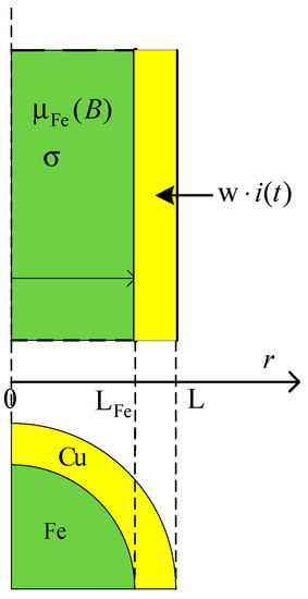
Figure 1.
Cross-section of the field-circuit system.
In the example shown, potential A depends only on r, so its derivative with respect to z is equal to zero.
The equations for a component of the magnetic potential A in axisymmetric coordinates depend only on radius r, z-coordinate, and time t.
Commonly used in numerical methods, the modification of the equations for has the form
where:
dla dla
dla , dla
—linear or non-linear magnetization characteristic of isotropic materials
; components of flux density
—average flux of winding’s cross-section area
W—number of conductors in winding’s cross-section area
—number of conductors per winding’s cross-section area
—height of the model in the z-axis.
The area of the magnetic field described by these equations, both space and time, has been discretized. The distribution of discretization points is shown in Figure 2.
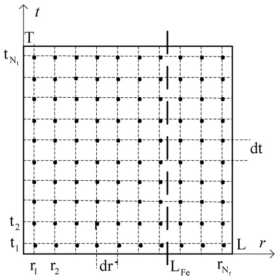
Figure 2.
Discretization grid of the space-time region.
The solution of Equation (1) is predicted in the form of a periodic function of two variables r and t approximated by a double Fourier series
This form of the Fourier series ensures the fulfillment of the Neumann condition on the edges of the region, which, given the condition makes the solution unambiguous. In the discrete version, the solution takes the form
where:
To solve the field-circuit problem in a discrete set of points, discrete differential operators differentiating with respect to r and t for functions and with respect to t for functions and were used. They relate the values of the respective partial derivatives to the function values at the grid points. How to create them is described below.
The first partial derivative with respect to r has the form:
or in discrete domain
The first partial derivative with respect to t has the form:
or in discrete domain
where: , , .
The potential values at the grid points are represented as a vector
The values of other functions at the grid points are arranged similarly.
In the presented approach, derivatives with respect to r and t are treated separately and discrete derivative operators are constructed separately for them. If we write the vector as a matrix
Then the derivative with respect to time will have the operator and will differentiate with respect to the columns i.e., , while the derivative with respect to r will have the operator and will differentiate with respect to the rows i.e., .
2.1. Discrete First-Derivative Operators with Respect to ‘r’
The inverse discrete cosine and sine transforms are used to construct the discrete first-derivative operators with respect to r because, after the first differentiation, the base of the series changes from cosine to sine.
The first-derivative operators with respect to r are also two, one of the cosine-sine base and second of the sine-cosine base and have the forms, respectively:
where —frequency matrix.
The operator can be used to calculate the magnetic flux density given the vector potential at time
where , .
For materials with linear magnetization characteristics, the second derivative of at time is calculated as
For non-linear materials, the term should be replaced with an expression
where and the vector has a form analogous to , and is a non-linear magnetization curve.
The matrices of cosine and sine transformations are almost unitary except for the element with index (1,1).
However, this does not distort the operation of the second derivative operator with respect to r, which is comprised of two first-derivative operators and , because element (1,1) concerns a constant signal, which is zeroed anyway as a result of multiplication by the frequency matrix . The operators and are, however, singular matrices.
2.2. Discrete Time First-Derivative Operator
A similar discretization as for r was performed for the time coordinate. The first derivative with respect to time can be computed using the discrete derivative operator with respect to time .
The inverse discrete Fourier transform was used to construct the discrete derivative operator
The operator of the first derivative with respect to time has the form
where —frequency matrix.
The first derivative of with respect to time at a distance is equal to , while the first derivative of the coil current and linked flux are given by and , where , are vectors:
2.3. Discrete Field-Circuit Equations
2.3.1. Discrete Field-Circuit Equations for a Linear System
In the two-dimensional (time-space) case reduced to a single vector of searched values A, the Kronecker tensor product was used.
If A1 is an n-by-m matrix and A2 is a matrix, then the Kronecker tensor product of A1 and A2 is a large matrix formed by multiplying by A2 each element of A1
The vector of discrete time-space values of the vector potential has the form
where the individual parts of A correspond to iron and copper areas and have the form
Vectors of time samples of current and voltage signals of the supply circuit have the following form:
Using the above, we can write the field-circuit equation for linear materials as follows:
where
- w—number of conductors per winding cross-section area
- —height of the model in the z-axis
2.3.2. Discrete Field-Circuit Equation for a Non-Linear System
For nonlinear magnetic materials, the field-circuit equation has the form
In which the vectors and have forms analogous to and . Their element values are computed from the characteristic of the ferromagnetic and copper material for each element of vector and , respectively, and g is the weight for the circuit equation.
The new operator matrices are calculated as follows:
2.4. Methodology of Solving Discrete Equations
The non-linear Equation (14) is solved by minimizing the function
Using MATLAB’s FMINUNC.
In addition, in order to converge the minimization process to the correct minimum value, a gradient and Hessian must also be provided
where:
And Hessian:
3. Calculation Results
The aim of the research is to demonstrate the usefulness of the method of discrete differential operators (DDOs) for the qualitative determination of physical phenomena, but also the accuracy of calculating the field values for non-linear and conductive magnetic materials. For testing, the coil is powered by a sinusoidal monoharmonic voltage that changes its amplitude and pulsation. The results obtained with the DDOs method were compared with the results obtained with the FEM method using the Ansys-Maxwell program.
In the discussed example, the system is axisymmetric and infinite in the z-axis. The space-time model applies to a segment with dimensions L = 12 mm LCu = 10 mm and the length of time equal to one period of the supply voltage. The fragment was discretized in the r axis ( points) and the t axis ( points). The equivalent external circuit (supplying the analyzed part of the coil) consists of a sinusoidal voltage u with an amplitude of 1.5 V and a small lumped resistance . The number of turns in this fragment was equal to W = 10. The following material constants for iron were assumed: bulk conductivity S/m, B-H curve Figure 3.
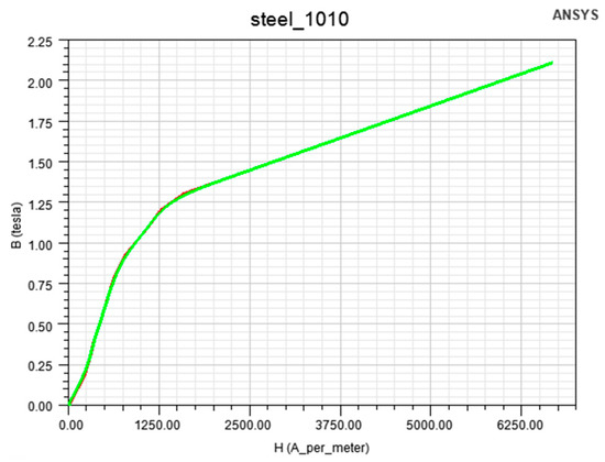
Figure 3.
B-H curve for magnetic core.
Figure 4 shows the coil current obtained by DDO and FEM for a sinusoidal voltage of 50 Hz, the amplitude of which is large enough to saturate the magnetic core, producing a characteristic non-sinusoidal current waveform mainly due to third harmonic.
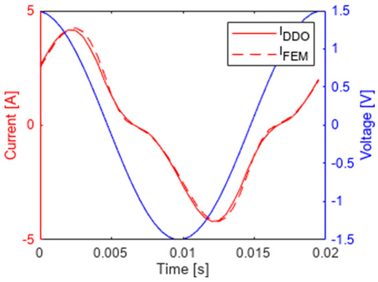
Figure 4.
The supply current obtained by the operator method IDDO and the FEM method IFEM as well as the supply voltage.
Figure 5 shows the difference between the currents calculated from the two aforementioned methods resulting mainly from the different grid adopted by Ansys (much dense FEM grid) and the fact that the Ansys-Maxwell program calculated the near-steady state, i.e., the fourth period of the transient state simulation.
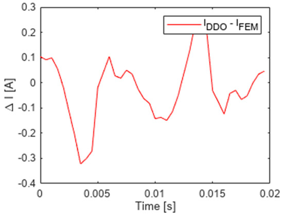
Figure 5.
The difference between the currents obtained by the operator method IDDO and the FEM method IFEM.
The flux function calculated by the operator is shown in Figure 6. Its changes in time and space could be drawn entirely on the “r-t” plane.
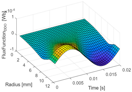
Figure 6.
Flux-function obtained by the operator method.
It should be noted that the cross-sections against the radius are nearly sinusoidal in time because the coil is supplied with monoharmonic voltage and the flux function should follow the shape of the voltage.
For small radiuses these functions are damped by eddy currents, which is well known phenomenon.
Also the difference between the calculation result obtained by the DDOs method and FEM is shown in Figure 7.
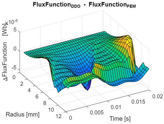
Figure 7.
The difference between the flux-function obtained by the operator method and the FEM method.
The calculation error between the operator and the FEM method is of the order of which means that both methods are comparable.
The magnetic induction waveforms at selected points for several radiuses (given in Table 1) are presented below.

Table 1.
Selected presentation points of waveform B.
In Figure 8 the waveforms are strongly nonlinear due to core saturation and are shifted in time due to eddy currents. Their magnitudes decrease lite bit inside core.
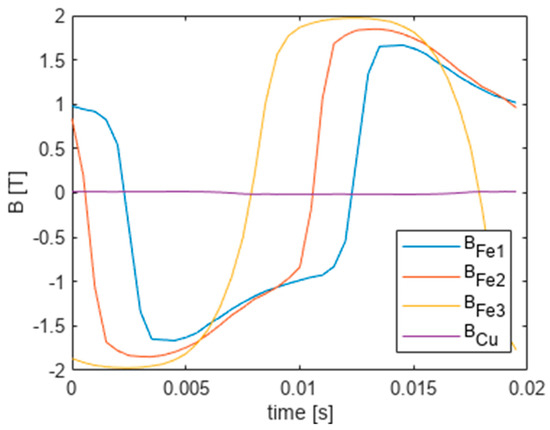
Figure 8.
Waveforms of flux density as a function of time at selected radiuses.
The next figure shows the changing of current density as a function of time and radius and the waveform of the current density at the points given in Table 1 is shown below (Figure 9).
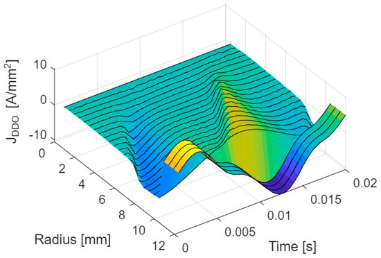
Figure 9.
Current density as a function of time and radius.
In Figure 10, the current density waveforms were obtained using the DDOs method. It can be observed that the waveforms in the core are in phase opposite to the coil current and are attenuated inside the core, which is a fundamental phenomenon for an alternating magnetic field in a conductive material. The non-linearity of their deformation depends on the radius.
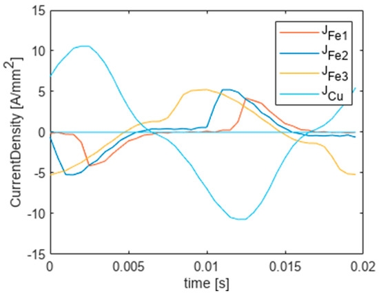
Figure 10.
Current density as a function of time at selected points (Table 1).
For comparison, Figure 11 shows the waveform of the current density obtained with the Ansys-Maxwell program in the fourth period of the transient state simulation at the same points r (Table 1). The waveforms keep the same character and both are qualitatively and quantitatively identical.
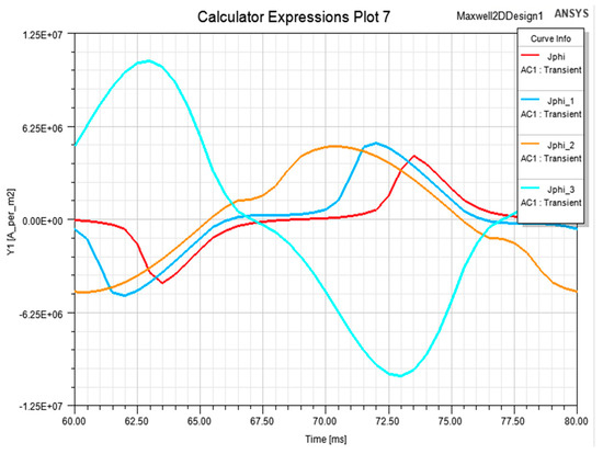
Figure 11.
Current density obtained with the Ansys-Maxwell program at selected points r (Table 1).
For test purposes, the magnitude of the supply voltage is significantly reduced to keep in linear part of B-H curve. Figure 12, Figure 13 and Figure 14 show the resulting waveforms of coil current, current density and flux density, respectively. All curves are almost sinusoidal but tendencies of current density and flux density for changes with the radius are kept.
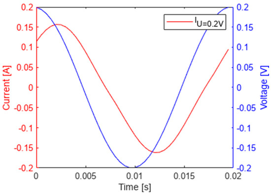
Figure 12.
Coil current obtained when amplitude of U is lowered to 0.2 V.
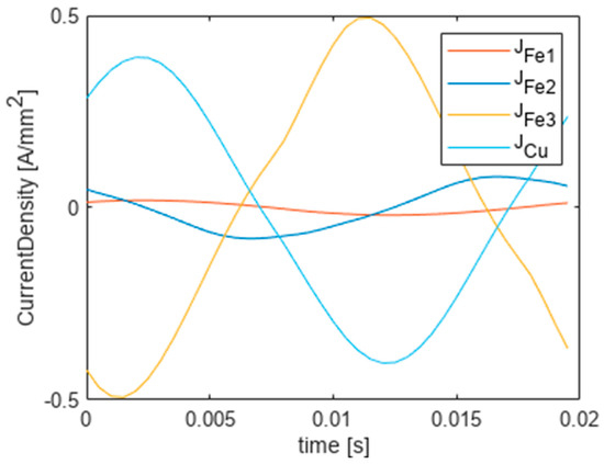
Figure 13.
Current density as a function of time at selected points (Table 1).
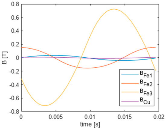
Figure 14.
Waveforms of flux density as a function of time at selected radiuses.
The lack of non-linear distortions results from lower magnetic induction values in the range of 0–0.8 T, i.e., in the range of linear changes.
Similar calculations were performed for the voltage excitation with 100 Hz pulsation.
The current and voltage waveforms of the field-excitation coil are shown below (Figure 15).
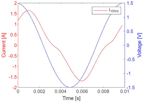
Figure 15.
Supply current obtained by the operator method IDDO.
The maximum current here is more than 2 times lower than at 50 Hz, therefore the core saturation is lower and the content of higher harmonics is lower.
The flux-function calculated by the DDOs is presented above the ‘r-t’ plane in Figure 16.
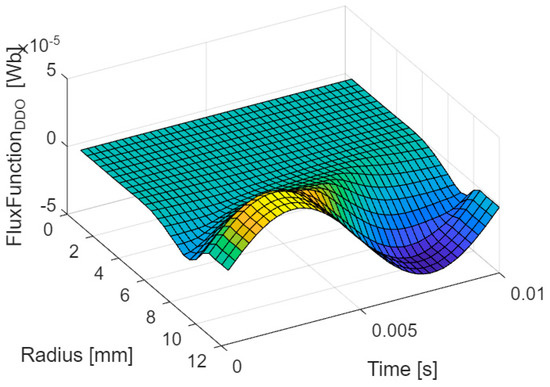
Figure 16.
Flux-function obtained by the DDOs method.
The following figures show the results of the DDOs calculations analogous to those for 50 Hz pulsations. Figure 17 shows the changing current density as a function of time and radius, it shows a clearly smaller penetration depth compared to the case for 50 Hz (see Figure 8).
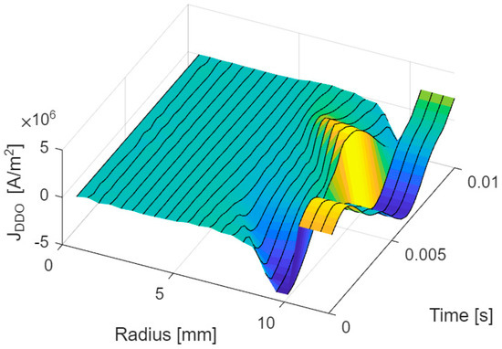
Figure 17.
Current density as a function of time and radius.
Due to the smaller range of the field impact (stronger skin-effect), other points (given in Table 2) were selected to present the waveforms

Table 2.
Selected measurement points for J waveforms.
The current density vs. time waveforms for several radius values given in Table 2 are shown below (Figure 18).
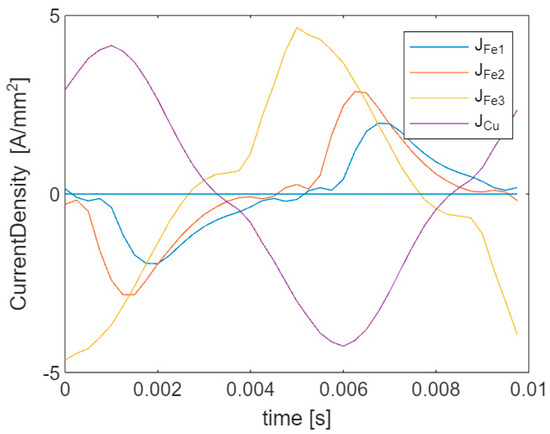
Figure 18.
Current density as a function of time at selected points r (Table 1).
A smaller field penetration (skin depth) is noticeable here, i.e., a faster decrease in the amplitudes of the induced currents with the distance from the supply winding.
The magnetic flux time waveforms at the same points r are shown below (Figure 19).
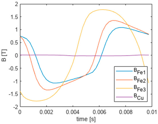
Figure 19.
Waveforms of flux density vs. time at selected points (Table 2).
4. Discussion
Calculations testing the proposed approach showed that the results very well reflect the qualitative and quantitative nature of both the current in the coil and the distribution of magnetic induction as well as eddy currents in the magnetic core. The quantitative assessment was made by comparing the results of the transient simulations with the commercial ANSYS package, confirming the very good quantitative agreement of the results, despite the much sparser rectangular space-time discretization grid for the discrete difference operators used. Calculation time using discrete differential operators was slightly shorter, despite the use of commonly available MATLAB procedures. The obtained calculations of the magnetic field and the supply current using the DDO method show all the characteristic relationships for the time-varying magnetic field in conductive and non-linear materials. The field suppression (skin effect) resulting from the theory and the decrease of the induced currents can be seen with changing the distance from the magnetizing winding. A stronger effect is obtained by increasing the frequency of the supply voltage. The currents induced in the iron are also reversed in phase with respect to the supply current. The field attenuation strongly depends also on the conductivity of the medium. The effect of entering into non-linearity and saturating the core is also visible and consistent with the theory and was quantitatively compared with the results from the almost steady state (obtained after several periods of transient state) in the Ansys program in which the same excitation and circuit were used for power supply.
5. Conclusions
DDO operators have already been used by us to solve a 2D stationary field, e.g., in a transformer window, where the cosine basis worked very well. It ensured the reversibility of the cosine transform operators, allowed the modeling of discontinuous fields at the edges of the region, and easy fulfillment of the Dirichlet and Neumann boundary conditions.
This time we presented an alternative method for the analysis of steady states in electromagnetic systems described by field-circuit models for nonlinear and conductive magnetic media. Discrete space-time differential operators, created in the paper, approximating the partial derivatives appearing in the field equations, and a discrete-time differential operator for magnetizing coils, were used for the analysis. This allowed direct calculations of steady states both in the magnetic core and in the coils, eliminating the calculation of transient states.
The proposed approach was tested on a simple case of a solenoid coil with ferromagnetic and conductive cylindrical core using two variables: the radius and time.
Author Contributions
Conceptualization, methodology, M.J. and T.J.S.; methodology, A.W. All authors have read and agreed to the published version of the manuscript.
Funding
This research received no external funding.
Data Availability Statement
No data available.
Conflicts of Interest
The authors declare no conflict of interest.
References
- Chari, M.V.K.; Salon, S.J. Numerical Methods in Electromagnetism; Academic Press: New York, NY, USA, 2000. [Google Scholar]
- Strikwerda, J.C. Finite Difference Schemes and Partial Differential Equations, 2nd ed.; Society for Industrial and Applied Mathematics: Philadelphia, PA, USA, 2004. [Google Scholar]
- LeVeque, R.J. Finite Difference Methods for Ordinary and Partial Differential Equations, 2nd ed.; Society for Industrial and Applied Mathematics: Philadelphia, PA, USA, 2007. [Google Scholar]
- Tang, R.; Wang, S.; Yan, L.; Wang, X.; Xiang, C. Transient simulation of power transformers using 3D finite element model coupled to electric circuit equations. IEEE Trans. Magn. 2000, 36, 1417–1420. [Google Scholar]
- Nowak, L.; Demenko, A. The 3D coupled field-circuit simulation of transients in converters with conducting solid parts. IEEE Trans. Magn. 2000, 36, 1412–1416. [Google Scholar]
- Brambilla, A. Method for steady-state simulation of strongly nonlinear circuits in the time domain. IEEE Trans. Circuits Syst. I Fundam. Theory Appl. 2001, 48, 885–889. [Google Scholar] [CrossRef]
- Schops, S.; De Gersem, H.; Bartel, A. Cosimulation framework for multirate time integration of field/circuit coupled problems. IEEE Trans. Magn. 2010, 46, 3233–3236. [Google Scholar] [CrossRef]
- Hara, T.; Naito, T.; Umoto, J. Time-periodic finite element method for nonlinear diffusions equations. IEEE Trans. Magn. 1985, 21, 2261–2264. [Google Scholar] [CrossRef]
- Biro, O.; Preis, K. An efficient time domain method for nonlinear periodic eddy current problems. IEEE Trans. Magn. 2006, 42, 695–698. [Google Scholar] [CrossRef]
- Takahashi, Y.; Tokumasu, T.; Fujita, M.; Wakao, S.; Fujiwara, K.; Ishihara, Y. Comparison between fast steady-state analysis methods for time-periodic nonlinear magnetic field problems. IEEE Trans. Magn. 2012, 48, 235–238. [Google Scholar] [CrossRef]
- Sobczyk, T.J. Algorithm for determining two-periodic steady-states in AC machines directly in time domain. Arch. Electr. Eng. 2016, 65, 575–583. [Google Scholar] [CrossRef][Green Version]
- Caron, G.; Henneron, T.; Piriou, F.; Mipo, J.-C. Time-periodic condition of nonlinear magneto-static problem coupled with electric circuit imposed by waveform relaxation method. IEEE Trans. Magn. 2016, 52, 7202604. [Google Scholar] [CrossRef]
- Caron, G.; Henneron, T.; Piriou, F.; Mipo, J.-C. Waveform relaxation–Newton method to determine steady state of an electromagnetic structure: Application to a three-phase transformer. COMPEL—Int. J. Comput. Math. Electr. Electron. Eng. 2017, 36, 729–740. [Google Scholar] [CrossRef]
- Sobczyk, T.J.; Radzik, M. A new approach to steady state analysis of nonlinear electrical circuits. COMPEL—Int. J. Comput. Math. Electr. Electron. Eng. 2017, 36, 716–728. [Google Scholar] [CrossRef]
- Sobczyk, T.; Radzik, M.; Tulicki, J. Direct steady-state solutions for circuit models of nonlinear electromagnetic devices. COMPEL—Int. J. Comput. Math. Electr. Electron. Eng. 2021, 40, 660–675. [Google Scholar] [CrossRef]
- Sobczyk, T. A reinterpretation of the Floquet solution of the ordinary differential equation system with periodic coefficients as a problem of infinite matrix. COMPEL—Int. J. Comput. Math. Electr. Electron. Eng. 1986, 5, 1–22. [Google Scholar] [CrossRef]
- Yamada, S.; Besho, K.; Lu, J. Harmonic balance finite element method application for nonlinear magnetic analysis. IEEE Trans. Magn. 1989, 25, 2971–2973. [Google Scholar] [CrossRef]
- Sobczyk, T.J. Direct determination of two-periodic solution for nonlinear dynamic systems. COMPEL—Int. J. Comput. Math. Electr. Electron. Eng. 1994, 13, 509–529. [Google Scholar] [CrossRef]
- Gyselinck, J.; Dular, P.; Geuzaine, C.; Legros, W. Harmonic-balance finite-element modeling of electromagnetic devices: A novel approach. IEEE Trans. Magn. 2002, 38, 521–524. [Google Scholar] [CrossRef]
- Deblecker, O.; Lobry, J. A new efficient technique for harmonic-balance finite element analysis of saturated devices. IEEE Trans. Magn. 2006, 38, 535–538. [Google Scholar] [CrossRef]
- Ausserhofer, S.; Bíró, O.; Preis, K. An efficient harmonic balance method for nonlinear eddy current problems. IEEE Trans. Magn. 2007, 43, 1229–1232. [Google Scholar] [CrossRef]
- Zhao, X.; Li, L.; Lu, J.; Cheng, Z.; Lu, T. Analysis of the saturated electromagnetic devices under CD bias condition by the decomposed harmonic balance method. COMPEL—Int. J. Comput. Math. Electr. Electron. Eng. 2012, 3, 498–513. [Google Scholar] [CrossRef]
- Sobczyk, T.; Jaraczewski, M. On simplified calculation of leakages inductances of power transformers. Energies 2020, 13, 4952. [Google Scholar] [CrossRef]
- Jaraczewski, M.; Sobczyk, T. Leakage inductances of transformers at arbitrarily located windings. Energies 2020, 13, 6464. [Google Scholar] [CrossRef]
- Sobczyk, T.; Jaraczewski, M. Application of discrete differential operators of periodic functions to solve 1D boundary-value problems. COMPEL—Int. J. Comput. Math. Electr. Electron. Eng. 2020, 39, 885–897. [Google Scholar] [CrossRef]
- Jaraczewski, M.; Sobczyk, T. Solving 2D boundary-value problems using discrete partial differential operators. COMPEL—Int. J. Comput. Math. Electr. Electron. Eng. 2022, 41, 703–719. [Google Scholar] [CrossRef]
Disclaimer/Publisher’s Note: The statements, opinions and data contained in all publications are solely those of the individual author(s) and contributor(s) and not of MDPI and/or the editor(s). MDPI and/or the editor(s) disclaim responsibility for any injury to people or property resulting from any ideas, methods, instructions or products referred to in the content. |
© 2023 by the authors. Licensee MDPI, Basel, Switzerland. This article is an open access article distributed under the terms and conditions of the Creative Commons Attribution (CC BY) license (https://creativecommons.org/licenses/by/4.0/).