Article

The Effect of a Magnetic Field on Solid–Liquid Contact Electrification for Streaming Flow Energy Harvesting

School of Mechanical Engineering, University of Ulsan, 93, Deahak-ro, Nam-gu, Ulsan 44610, Republic of Korea
*
Author to whom correspondence should be addressed.
Energies 2023, 16(12), 4779; https://doi.org/10.3390/en16124779
Submission received: 22 April 2023 / Revised: 11 June 2023 / Accepted: 16 June 2023 / Published: 18 June 2023
(This article belongs to the Section K: State-of-the-Art Energy Related Technologies)

Abstract

:
In recent years, the triboelectric nanogenerator (TENG) has been recognized as a promising method for energy harvesting and self-powered devices. However, in order to improve the output efficiency of the TENG, it is necessary to change the types of dielectric materials, which requires advanced technology and a high cost to implement. To address this issue, we developed a parallel electrode magnetic-TENG (Mag-TENG) based on contact electrification of a liquid–solid interface under the effect of the magnetic field, which enhances the output performance of the TENG without having to develop the dielectric material. Our experimental results achieved a higher output of the TENG under the influence of a magnetic field when an increase of the magnetic field strength went from 0 to 360 mT, and the flow rate of unsteady seawater was variable from 390 to 690 mL/min. Specifically, compared to the without-magnetic field case, the output current increased by approximately 6.5 times and the output voltage by 2.7 times. These findings suggested that using a magnetic field to enhance the TENG’s efficiency has significant potential for energy harvesting from seawater and self-powered flow sensors.

1. Introduction

Currently, the Internet of Things (IoT) has witnessed significant advancements and has become increasingly pervasive in human lives, so making and sharing data collection has become easier and more seamless. However, the limitations of battery life and the necessity of recharging poses challenges, particularly for devices situated in remote or inaccessible locations [1]. Therefore, the development of self-powered technologies is essential nowadays.
The triboelectric nanogenerator (TENG) is considered an effective solution to remedy the above problem when generating power through ambient mechanical energy in the environment [2,3,4,5]. Therefore, the IoT devices are powered by the TENG device, which can eliminate the need for external power sources or battery replacements [6]. Since being first introduced by Wang’s group in 2012 [7], it has opened up a new era for renewable energy [8,9]. Besides, the TENG has other advantages, such as the low cost and ease of fabrication, simple operation, high efficiency, eco-friendliness, and being lightweight [10,11]. Based on the materials involved in the triboelectric interaction, the TENG has a lot of different variations. Among them, the solid–solid interface structure (SS-TENG) is rated with the highest output efficiency through the contact and separation of two solid materials with different triboelectric properties [12,13,14]. However, the friction generated between two solid materials causes surface abrasion along with environmental factors (temperature, humidity) that reduces the efficiency and lifetime of the SS-TENGs. Therefore, the appearance of a solid–liquid interface (LS-TENG) is an effective solution to overcome the limitations of the SS-TENG and harvest energy from the liquid [5], especially in conditions of low frequency and small scale [15,16,17]. In general, the TENG technology can solve the problem of self-powered IoT devices, but the output of the TENG is still low and needs to be improved to diversify applications for electronic devices.
To overcome the above problem, the combination of an electromagnetic generator (EMG) and a TENG is an efficient conversion method that enhances the performance of the TENG and harnesses the advantages of both types of technology [18,19,20]. C. Hou et al. [21] proposed the rotational pendulum that generated energy from human motion based on the combined EMG and TENG. H. Yang et al. [22] developed a hybrid device rolling waterwheel-like rolling. The TENG was generated when it integrated silicon rubber magnets rolled/slid over the electrodes, and EMG was formed when the magnet passed through a preset region of copper coils under the rolling of the water wheel. However, since the output characteristics of EMGs and TENGs are different, it is difficult to directly connect their output signals. Thus, it is necessary to develop a converter circuit that can directly store the output power from the hybridized device [23,24]. For this reason, magnetized materials are being developed to replace the tribomaterials while maintaining the originality of the TENG and applying a magnetic field to enhance its output performance [25,26,27]. The internal microstructure of the material is changed due to the influence of the magnetic field, which affects the output performance of the TENG. R. Sun et al. [28] approached the magnetic polymeric composite film when using the magnetic field to fill particle concentration and particle size inside the film, leading to an enhanced output of the TENG. S. Hajra et al. reported a method that enhanced the surface charge potential of dielectric materials by using multiferroic materials [29]. On the other hand, Y. Li et al. [30] demonstrated that using ferromagnetic electrodes also increased the output of the TENG under the effect of the magnetic field. Nevertheless, the production procedures for these materials are extremely complex and quite expensive, involving advanced equipment. Therefore, studying the influence of the magnetic field on the performance of the TENG without changing the dielectric material is necessary now.
In this study, we developed a parallel electrode magnetic-TENG (Mag-TENG) that can undergo direct charge transfer between two electrodes based on the contact electrification (CE) of seawater and a Cu electrode. The order and direction of the charge in the electrolyte liquid were rearranged under the influence of the Lorentz force, leading to a significantly enhanced output performance by the TENG. Simultaneously, direct-current (DC) power was generated without having to use a converter circuit (as is necessary for hybridized TENG devices) when the streaming flows were pumped through the Mag-TENG pipe. Experiments included changing the strength and direction of the magnetic field to verify its effect on the TENG’s efficiency. Furthermore, the flow rate, electrolyte concentration, and distance between the two electrodes were also investigated. The experimental results showed that the magnetic field improved the performance of the TENG by 6.5 times in the output current and 2.7 times in the output voltage. This work thus offers a critical understanding of how the magnetic field affects the mechanism of charge arrangement and transport inside the liquid, as well as a potential method for improving the efficiency of TENGs in harvesting and self-powered devices.

2. Materials and Methods

2.1. Fabrication of the Mag-TENG Device

The Mag-TENG device was constructed using two main components: a Mag-TENG pipe and a magnet. The Mag-TENG was designed, as shown in Figure 1a, comprising a (L) large electrode (5 × 25 mm) and a (S) small electrode (5 × 10 mm) placed parallel to each other within electrode holders. The pipes were fabricated from a clear resin material (Formlabs Form 2, USA) using a 3D printer, with two different inner diameters (either D1 = 6.5 mm or D2 = 10 mm) to maintain consistent flow rates throughout the pipeline. The assembled Mag-TENG pipe was then mounted on a shelf, as depicted in Figure 1c, and permanent block magnets (20 × 35 × 5 mm and 10 × 35 × 5 mm) were added to the device. This approach allowed us to create a reliable and robust Mag-TENG structure that was suitable for experimental investigation.

2.2. Characterization and Electrical Measurement

The magnetic field effect was adjusted by assembling multiple block magnets, and a Tesla meter (KANETEC TM-801EXP, Tokyo, Japan) was used to measure the magnetic field effect when the voltage was changed. The output voltage and current of the TENG were measured by using an electrometer (Keithley DMM7510, Solon, OH, USA) as well as by collecting data from the TENG device. The flow rate of the system is adjusted by using a peristaltic pump (ISM1076A, Mettmann, Germany).

2.3. Working Principle of the Mag-TENG

The experimental setup for the Mag-TENG system is shown in Figure 1c. It includes a pump to deliver the water from the tank to the Mag-TENG pipe and an electrometer to measure the output signal. The experimental system investigates the effect of different flow rates of water, used as the water phase, with varying magnetic field strengths. To complete the solid phase in the TENG, a polyvinylidene difluoride (PVDF) membrane is inserted inside Pipe 1 as a dielectric layer. Two different-sized electrodes are then hooked up to the electrode holder and installed parallel to each other inside Pipe 1. Finally, Pipe 2 is installed to prevent water leakage from the area of the two electrodes. When water flows inside the Mag-TENG pipe, water is affected by the solid phase of the TENG and generates electricity between the two electrodes. The following section reports on the investigation of the effect of the magnetic field on the electrical output performance when placed between the two electrodes.
The working principle of the Mag-TENG system can be classified into two categories: without and with the magnetic field effect. Figure 2a illustrates the TENG mechanism without the magnetic field effect when water (seawater) is pumped by a three-roller peristaltic pump. As water flows into the pipe, CE occurs between water and the PVDF layer, resulting in negative charges on the contact surface. Positive ions that exist in the water, such as H+ and Na+, migrate toward the PVDF surface, while loosely negative ions, such as OH and Cl, are repelled away due to the electrostatic interactions, leading to the formation of a positively charged electric double layer (EDL) [31] (Figure 2(a-i)). As a result, the water has an excess negative charge in the diffuse layer [26]. The unsteady streaming flow inside the pipe, due to the peristaltic pump, can be divided into two cases: compression and restitution [25,31]. When water encounters the two electrodes, the negative ions become concentrated on the surface of the two electrodes and an EDL is formed at the water/Cu-electrode interfaces (see Figure 2(a-ii)). The EDL can be considered as a capacitor, and the capacitance at the large and small electrodes can be denoted as CL and Cs, respectively [32]. This capacitance can be given as follows:
C i = ε A i d
where i corresponds to the electrode size (i = L-large or S-small electrode), ε is the permittivity of the seawater, Ai is the area of the electrodes (AL/AS), and d is the thickness of the EDL layer. Accordingly, the concentration of ions on the two electrodes is not equal due to their different areas; they are concentrated mostly in the large electrode, leading to the charge on the large electrode as always being bigger than the small electrode (CL > Cs) [33]. This creates an electric potential difference between the two electrodes, causing electrons to always transfer from the large electrode into the small electrode, and, as a result, generating the DC output. This electron transfer generates an electrical current in the external circuit, as shown in Figure 2d:
V L t V S t = Q L q t C L t Q S + q t C S t = R l o a d + R W d q t d t
where QL and QS represent the surface charges stored on the large and small electrodes, respectively. Rload is the load resistance, RW is the internal resistance of water, and q(t) is the increment or decrement of charge at time t. When the flow rate increases, the EDL is broken by a greater flow force, which overcomes the electrostatic force. This results in an increased charge distribution on both electrodes, causing the magnitude of the output to increase as the compression flow approaches its maximum value (Figure 2(a-iii)). The output then gradually decreases as it passes through the restitution flow state (Figure 2(a-iv,a-v)), completing the TENG cycle. Thereby, the DC output is generated continuously (Figure 2b), but the output magnitude varies, depending on the flow rate of the fluid. This is illustrated in more detail by magnifying one cycle (Figure 2c).
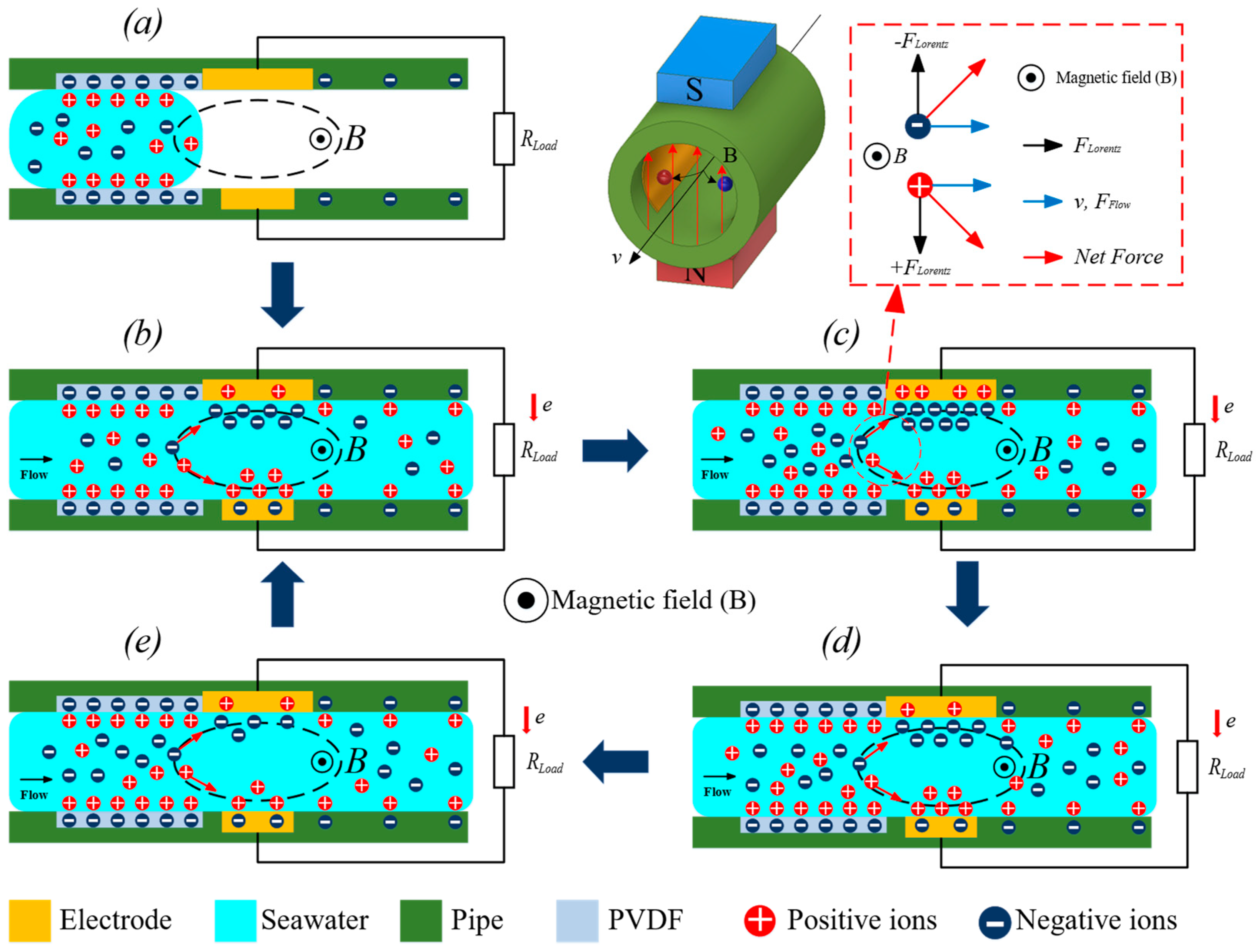
To enhance the output performance of the TENG, we applied a magnetic field between the two electrodes to rearrange the distribution of ions. The concentration of negative ions on the surface of both electrodes typically reduces the charge transfer, leading to a low TENG output. However, when a magnetic flux is applied, the Lorentz force moves the ions in a particular direction according to the “right-hand rule” [34], increasing the number of ions moving toward the electrodes. The Lorentz force magnitude and direction is dependent on the electric charge of the ions, charge velocity, and magnetic field strength, as given by Equation (3). Consequently, the ions in the diffuse layer move toward both sides of the electrodes, increasing q(t) significantly compared to the case without a magnetic field.
F = B . v . q L
where F is the Lorentz force, q L is the electric charge of the ions, v is the charge velocity and B is the magnetic field strength.
Figure 3 illustrates the working principle of the Mag-TENG when a magnetic field is applied. The ellipse represents the magnetic field’s direction of movement from the inside to the outside. In the initial state, water flows into the magnetic field zone, as shown in Figure 3a. As the water enters the magnetic field due to the compression flow (Figure 3b), the magnetic field affects the ions in the water, making them migrate toward both sides of the electrodes. Positive ions become concentrated in the small electrode, while negative ions move toward the large electrode, forming an EDL on both electrodes. Electrons from the large electrode move to the small electrode and react with the positive ions in the water on the surface of the small electrode. The number of moving electrons to the small electrode increases as the compression flow rate is maximized (Figure 3c) and decreased in the restitution flow state (Figure 3d–e). Thus, the output of the Mag-TENG was still the DC power, demonstrating that the system can generate electricity without requiring a converter. Harvesting the streaming flow energy from the water and converting it into DC power is the highlight of the Mag-TENG system.

3. Results and Discussions

To investigate the impact of a magnetic field on the performance of the Mag-TENG, magnets were incorporated into the device. The magnetic field strength was adjusted by either joining or separating the magnets (Figure 1c), and it was varied from 0 to 360 mT while the water flow rate was changed from 390 to 650 mL/min. Two pipes with different diameters (D1 = 6.5 mm and D2 = 10 mm) were utilized in the experiment. The output current and voltage from the Mag-TENG device were measured at a flow rate of 390 mL/min using the D2 pipe without and with a magnetic field of 360 mT, which produced peak-to-peak output current values of 254 and 533 nA, and peak output voltage values of 0.5 and 1.0 mV, respectively. Although the output voltage was still low, the charge transfer value was increased on both pipes by the magnetic field’s effect (as shown in Figure S1). Moreover, the maximum output current and voltage were obtained with the D1 and D2 pipes when the magnetic field strength and flow rate were increased, reaching 970 nA and 1.31 mV with the D1 pipe and 839 nA and 1.49 mV, respectively (Figure 4b,c). To provide a visual representation of the effect of the magnetic field, a video showcasing the change in the Mag-TENG output during the experiment is displayed in Supporting Information Video S1.
In previous studies, the output performance of a TENG is affected by the flow rate of the fluid and the type of dielectric materials. However, in this research, the magnetic field played an important role in increasing the output of the Mag-TENG without replacing the dielectric/electrode material due to several factors. First, the weak electrostatic attraction force between the Cu electrode and negative ions compared to other dielectric materials led to a reduced output performance in the absence of a magnetic field. Second, both electrodes used were a copper material. When in an environment without the magnetic field, negative ions were attracted to the surface of the two electrodes to form the EDL layer due to electrostatic force—this led to a low charge difference between the two surfaces (shown in Figure 2a). Meanwhile, when applying the magnetic field into the Mag-TENG, ions were separated on the sides based on their charge and concentrated on the surface of the two electrodes by the Lorentz force (described in Figure 3). Therefore, the surface charges stored on both electrodes were significantly increased. This theory was expressed more clearly at the output of the Mag-TENG, which gradually increased when increasing the magnetic field strength from 0 to 360 mT, as shown in Figure 4b,c. As a result, the current and voltage generated in the case with the applied magnetic field were 6.5 and 2.7 times higher using D1, and 3 and 2.3 times higher using D2 than those in the case without a magnetic field, respectively. According to the experiment result, the output electric signals of the Mag-TENG were directly proportional to both the water flow rate and the magnetic field in the range from 390 to 650 mL/min and the magnetic field strength from 0 to 360 mT, respectively. However, when the flow rate exceeded 650 mL/min, the output gradually decreased due to the increased flow force, which reduced the Lorentz force’s ability to pull charges to the electrode’s surfaces (shown in Figure S2). Additionally, increasing the magnetic field strength was challenging and required assembling multiple block magnets, which can increase the attraction between the poles and cause tube damage. Moreover, using high-strength magnets or increasing the magnetic field strength can pose a danger to the experimenters. Therefore, to achieve optimal efficiency, a flow rate of 650 mL/min and magnetic field strength of 360 mT were recommended for the Mag-TENG.
To further investigate the impact of the magnetic field on the performance of the Mag-TENG, a rotary magnetic system was implemented. This system can change the direction of the magnetic field in a range from 0 to 180° and is illustrated in Figure 5a–c. Magnets were located on a holder and connected to the Mag-TENG pipe by using a bearing. The angles between the magnetic system were varied horizontally from 0° to 180°, and the corresponding outputs of the Mag-TENG using pipe D1 were recorded and plotted in Figure 5d. The results demonstrated that the highest output values were obtained at an angle of 90°, with a peak current and voltage of 170 nA and 0.23 mV, respectively. In contrast, the lowest values were observed at 0° and 180°. This outcome can be attributed to the ions’ movement in response to a magnetic field following the “right-hand” rule; at 0° and 180°, the ions move above and below the pipe with only a few ions concentrated on either side of the electrode. Consequently, the efficiency of the Mag-TENG at these two angles was only modest, with output current values of 20 and 10 nA, and output voltage values of 0.07 and 0.05 mV, respectively. Briefly, the direction of the magnetic field was an important factor that impacted the performance of the TENG, with 90° being the optimal angle for maximum efficiency.
The experimental results demonstrated that the magnetic field played a crucial role in influencing the output performance of the TENG by acting on the ions in the water and forcing them to follow the law of magnetic force. However, an important aspect that needs further examination was the reason for using seawater in this study. Therefore, a comparison was conducted between using seawater or deionized (DI) water in the Mag-TENG while applying a magnetic field. Figure 5e shows the output current of the Mag-TENG with the two types of water. It was observed that the output current of the DI water case remained almost unchanged (480 nA) when the magnetic field strength was increased, whereas the output current of the seawater case significantly increased (from 148 to 970 nA). It is known that seawater contains large numbers of Na+ and Cl ions and the action of the Lorentz force on them causes their detachment from either side of the two electrodes. On the contrary, DI water does not contain ions and was almost unaffected by the magnetic field. In addition, when applying the magnetic field, the output voltage of the seawater case increased, while that of the DI water case only slightly changed (Figure 5f).
Furthermore, the NaCl concentration inside seawater was considered in this study, and Figure 6 depicts the experimental results of NaCl concentrations that vary from 0 to 34 g/L in pipes D1 and D2 (as the NaCl concentration in seawater is approximately 34 g/L). The results indicated that the output of the Mag-TENG significantly increased when the NaCl concentration inside the water was increased. Specifically, the output current increased to 0.32 µA when increasing the concentration from 5 g/L to 34 g/L in pipe D1 and raised by 0.4 µA in pipe D2. Meanwhile, the output voltage increased by 0.5 mV and 0.6 mV, respectively. The reason for this is that as the concentration of NaCl increased, it led to the number of Na+ and Cl ions also growing. Therefore, when passing through the magnetic field, the number of ions concentrated on the surface of the two electrodes enhanced, resulting in a boost in the output performance of the Mag-TENG. As a result, the concentration of NaCl is proportional to the output performance of the Mag-TENG.
Clearly, the magnetic field and NaCl concentration play a vital role in improving the TENG efficiency by influencing the ions in the water. For practical applications, a 1 μF capacitor was charged by the Mag-TENG with a pipe diameter of 25 mm, a flow rate of 600 mL/min, and a magnetic field strength of 160 mT. The result is shown in Figure S3, which demonstrates that the Mag-TENG can directly charge the capacitor without a rectifier circuit. This finding provided a promising method for energy harvesting and/or self-powered devices.

4. Conclusions

In summary, we have successfully demonstrated the effectiveness of using a magnetic field to improve the output performance of a Mag-TENG pipe with parallel electrodes in an unsteady seawater flow. Our results showed that the output of the Mag-TENG increased by approximately 6.5 times the output current and 2.7 times the output voltage when compared with the without magnetic. More importantly, the Mag-TENG could also generate DC output, so it has the ability to connect directly to drive electronic devices. Besides, the output of the Mag-TENG and the seawater flow rate exhibited a linear relationship, making it a promising technology for use in self-powered flow sensors. Although the outputs were low when compared with other TENG studies, this is a new research direction when investigating the direct influence of magnetic fields on the TENG when magnetized materials are not used. Therefore, the Mag-TENG shows great potential for harvesting energy from seawater or for use in self-powered flow sensors.

Supplementary Materials

The following supporting information can be downloaded at: https://www.mdpi.com/article/10.3390/en16124779/s1. Figure S1: The transfer charge of the Mag-TENG. (a) The measure on pipe D1 and (b) on pipe D2 under a flow rate of 650 mL/min; Figure S2: (a) The output current and (b) the output voltage from the Mag-TENG under a D1 pipe and range of flow rate from 130 to 1170 mL/min with a magnetic field strength of 360 mT; Figure S3: The application of the Mag-TENG to charge a capacitor; Video S1: Demonstration of the effect of magnetic to the output of Mag-TENG.

Author Contributions

Conceptualization, T.H.N.; Methodology, T.H.N.; Investigation, T.H.N.; Writing—original draft preparation, T.H.N.; Writing—review and editing, T.H.N. and K.K.A.; Visualization, T.H.N.; Supervision, K.K.A.; Project administration, K.K.A. All authors have read and agreed to the published version of the manuscript.

Funding

This research was supported by the Basic Science Program through the National Research Foundation of Korea (NRF), funded by the Ministry of Science and ICT, South Korea (NRF 2020R1A2B5B03001480), “Regional Innovation Strategy (RIS)” through the National Research Foundation of Korea (NRF), and funded by the Ministry of Education (MOE) (2021RIS-003).

Institutional Review Board Statement

Not applicable.

Informed Consent Statement

Not applicable.

Data Availability Statement

The authors confirm that the data supporting the finding of this study is available within the article.

Conflicts of Interest

The authors declare no conflict of interest.

References

  1. Alsharif, M.H.; Jahid, A.; Kelechi, A.H.; Kannadasan, R. Green IoT: A Review and Future Research Directions. Symmetry 2023, 15, 757. [Google Scholar] [CrossRef]
  2. Jiang, D.; Lian, M.; Xu, M.; Sun, Q.; Xu, B.B.; Thabet, H.K.; El-Bahy, S.M.; Ibrahim, M.M.; Huang, M.; Guo, Z. Advances in triboelectric nanogenerator technology—Applications in self-powered sensors, Internet of things, biomedicine, and blue energy. Adv. Compos. Hybrid Mater. 2023, 6, 57. [Google Scholar] [CrossRef]
  3. Wang, Z.L.; Jiang, T.; Xu, L. Toward the blue energy dream by triboelectric nanogenerator networks. Nano Energy 2017, 39, 9–23. [Google Scholar] [CrossRef]
  4. Li, X.; Tao, J.; Wang, X.; Zhu, J.; Pan, C.; Wang, Z.L. Networks of High Performance Triboelectric Nanogenerators Based on Liquid–Solid Interface Contact Electrification for Harvesting Low-Frequency Blue Energy. Adv. Energy Mater. 2018, 8, 1800705. [Google Scholar] [CrossRef]
  5. Lin, S.; Zheng, M.; Wang, Z.L. Detecting the Liquid–Solid Contact Electrification Charges in a Liquid Environment. J. Phys. Chem. C 2021, 125, 14098–14104. [Google Scholar] [CrossRef]
  6. Xi, F.; Pang, Y.; Liu, G.; Wang, S.; Li, W.; Zhang, C.; Wang, Z.L. Self-powered intelligent buoy system by water wave energy for sustainable and autonomous wireless sensing and data transmission. Nano Energy 2019, 61, 1–9. [Google Scholar] [CrossRef]
  7. Fan, F.-R.; Tian, Z.-Q.; Wang, Z.L. Flexible triboelectric generator. Nano Energy 2012, 1, 328–334. [Google Scholar] [CrossRef]
  8. Wang, Z.L.; Wang, A.C. On the origin of contact-electrification. Mater. Today 2019, 30, 34–51. [Google Scholar] [CrossRef]
  9. Zou, H.; Zhang, Y.; Guo, L.; Wang, P.; He, X.; Dai, G.; Zheng, H.; Chen, C.; Wang, A.C.; Xu, C.; et al. Quantifying the triboelectric series. Nat. Commun. 2019, 10, 1427. [Google Scholar] [CrossRef] [PubMed] [Green Version]
  10. Wang, Z.L. On Maxwell’s displacement current for energy and sensors: The origin of nanogenerators. Mater. Today 2017, 20, 74–82. [Google Scholar] [CrossRef]
  11. Nguyen, Q.-T.; Ahn, K.-K.K. Fluid-Based Triboelectric Nanogenerators: A Review of Current Status and Applications. Int. J. Precis. Eng. Manuf.-Green Technol. 2020, 8, 1043–1060. [Google Scholar] [CrossRef]
  12. Mi, H.-Y.; Jing, X.; Zheng, Q.; Fang, L.; Huang, H.-X.; Turng, L.-S.; Gong, S. High-performance flexible triboelectric nanogenerator based on porous aerogels and electrospun nanofibers for energy harvesting and sensitive self-powered sensing. Nano Energy 2018, 48, 327–336. [Google Scholar] [CrossRef]
  13. Wang, H.; Wang, J.; He, T.; Li, Z.; Lee, C. Direct muscle stimulation using diode-amplified triboelectric nanogenerators (TENGs). Nano Energy 2019, 63, 103844. [Google Scholar] [CrossRef]
  14. Feng, Y.; Zheng, Y.; Zhang, G.; Wang, D.; Zhou, F.; Liu, W. A new protocol toward high output TENG with polyimide as charge storage layer. Nano Energy 2017, 38, 467–476. [Google Scholar] [CrossRef]
  15. Lin, S.; Chen, X.; Wang, Z.L. The tribovoltaic effect and electron transfer at a liquid-semiconductor interface. Nano Energy 2020, 76, 105070. [Google Scholar] [CrossRef]
  16. Lin, S.; Xu, L.; Wang, A.C.; Wang, Z.L. Quantifying electron-transfer in liquid-solid contact electrification and the formation of electric double-layer. Nat. Commun. 2020, 11, 399. [Google Scholar] [CrossRef] [Green Version]
  17. Xu, M.; Wang, S.; Zhang, S.L.; Ding, W.; Kien, P.T.; Wang, C.; Li, Z.; Pan, X.; Wang, Z.L. A highly-sensitive wave sensor based on liquid-solid interfacing triboelectric nanogenerator for smart marine equipment. Nano Energy 2019, 57, 574–580. [Google Scholar] [CrossRef]
  18. Wang, Z.; Yu, Y.; Wang, Y.; Lu, X.; Cheng, T.; Bao, G.; Wang, Z.L. Magnetic Flap-Type Difunctional Sensor for Detecting Pneumatic Flow and Liquid Level Based on Triboelectric Nanogenerator. ACS Nano 2020, 14, 5981–5987. [Google Scholar] [CrossRef]
  19. Hao, C.; He, J.; Zhai, C.; Jia, W.; Song, L.; Cho, J.; Chou, X.; Xue, C. Two-dimensional triboelectric-electromagnetic hybrid nanogenerator for wave energy harvesting. Nano Energy 2019, 58, 147–157. [Google Scholar] [CrossRef]
  20. Cao, R.; Zhou, T.; Wang, B.; Yin, Y.; Yuan, Z.; Li, C.; Wang, Z.L. Rotating-Sleeve Triboelectric–Electromagnetic Hybrid Nanogenerator for High Efficiency of Harvesting Mechanical Energy. ACS Nano 2017, 11, 8370–8378. [Google Scholar] [CrossRef]
  21. Hou, C.; Chen, T.; Li, Y.; Huang, M.; Shi, Q.; Liu, H.; Sun, L.; Lee, C. A rotational pendulum based electromagnetic/triboelectric hybrid-generator for ultra-low-frequency vibrations aiming at human motion and blue energy applications. Nano Energy 2019, 63, 103871. [Google Scholar] [CrossRef]
  22. Yang, H.; Wang, M.; Deng, M.; Guo, H.; Zhang, W.; Yang, H.; Xi, Y.; Li, X.; Hu, C.; Wang, Z. A full-packaged rolling triboelectric-electromagnetic hybrid nanogenerator for energy harvesting and building up self-powered wireless systems. Nano Energy 2019, 56, 300–306. [Google Scholar] [CrossRef]
  23. Saadatnia, Z.; Esmailzadeh, E.; Naguib, H.E. Design, simulation, and experimental characterization of a heaving triboelectric-electromagnetic wave energy harvester. Nano Energy 2018, 50, 281–290. [Google Scholar] [CrossRef]
  24. Feng, L.; Liu, G.; Guo, H.; Tang, Q.; Pu, X.; Chen, J.; Wang, X.; Xi, Y.; Hu, C. Hybridized nanogenerator based on honeycomb-like three electrodes for efficient ocean wave energy harvesting. Nano Energy 2018, 47, 217–223. [Google Scholar] [CrossRef]
  25. Lin, S.; Zhu, L.; Tang, Z.; Wang, Z.L. Spin-selected electron transfer in liquid–solid contact electrification. Nat. Commun. 2022, 13, 5230. [Google Scholar] [CrossRef]
  26. Wang, X.; Yang, Y. Effective energy storage from a hybridized electromagnetic-triboelectric nanogenerator. Nano Energy 2017, 32, 36–41. [Google Scholar] [CrossRef]
  27. Wang, S.; Yuan, F.; Liu, S.; Zhou, J.; Xuan, S.; Wang, Y.; Gong, X. A smart triboelectric nanogenerator with tunable rheological and electrical performance for self-powered multi-sensors. J. Mater. Chem. C 2020, 8, 3715–3723. [Google Scholar] [CrossRef]
  28. Sun, R.; Gao, L.; Shou, M.; Li, B.; Chen, X.; Wang, F.; Mu, X.; Xie, L.; Liao, C. Tribo-material based on a magnetic polymeric composite for enhancing the performance of triboelectric nanogenerator. Nano Energy 2020, 78, 105402. [Google Scholar] [CrossRef]
  29. Hajra, S.; Vivekananthan, V.; Sahu, M.; Khandelwal, G.; Raj, N.P.M.J.; Kim, S.-J. Triboelectric nanogenerator using multiferroic materials: An approach for energy harvesting and self-powered magnetic field detection. Nano Energy 2021, 85, 105964. [Google Scholar] [CrossRef]
  30. Li, Y.; Li, G.; Zhang, P.; Zhang, H.; Ren, C.; Shi, X.; Cai, H.; Zhang, Y.; Wang, Y.; Guo, Z.; et al. Contribution of Ferromagnetic Medium to the Output of Triboelectric Nanogenerators Derived from Maxwell’s Equations. Adv. Energy Mater. 2021, 11, 2003921. [Google Scholar] [CrossRef]
  31. Lin, S.; Chen, X.; Wang, Z.L. Contact Electrification at the Liquid–Solid Interface. Chem. Rev. 2021. [Google Scholar] [CrossRef] [PubMed]
  32. Xu, W.; Zheng, H.; Liu, Y.; Zhou, X.; Zhang, C.; Song, Y.; Deng, X.; Leung, M.; Yang, Z.; Xu, R.X.; et al. A droplet-based electricity generator with high instantaneous power density. Nature 2020, 578, 392–396. [Google Scholar] [CrossRef] [PubMed]
  33. Ding, J.; Tao, W.-Q.; Fan, S.-K. Study of vibrational droplet triboelectric nanogenerator on structural and operational parameters. Nano Energy 2020, 70, 104473. [Google Scholar] [CrossRef]
  34. Al Helal, A.; Soames, A.; Gubner, R.; Iglauer, S.; Barifcani, A. Influence of magnetic fields on calcium carbonate scaling in aqueous solutions at 150 °C and 1 bar. J. Colloid Interface Sci. 2018, 509, 472–484. [Google Scholar] [CrossRef] [PubMed] [Green Version]
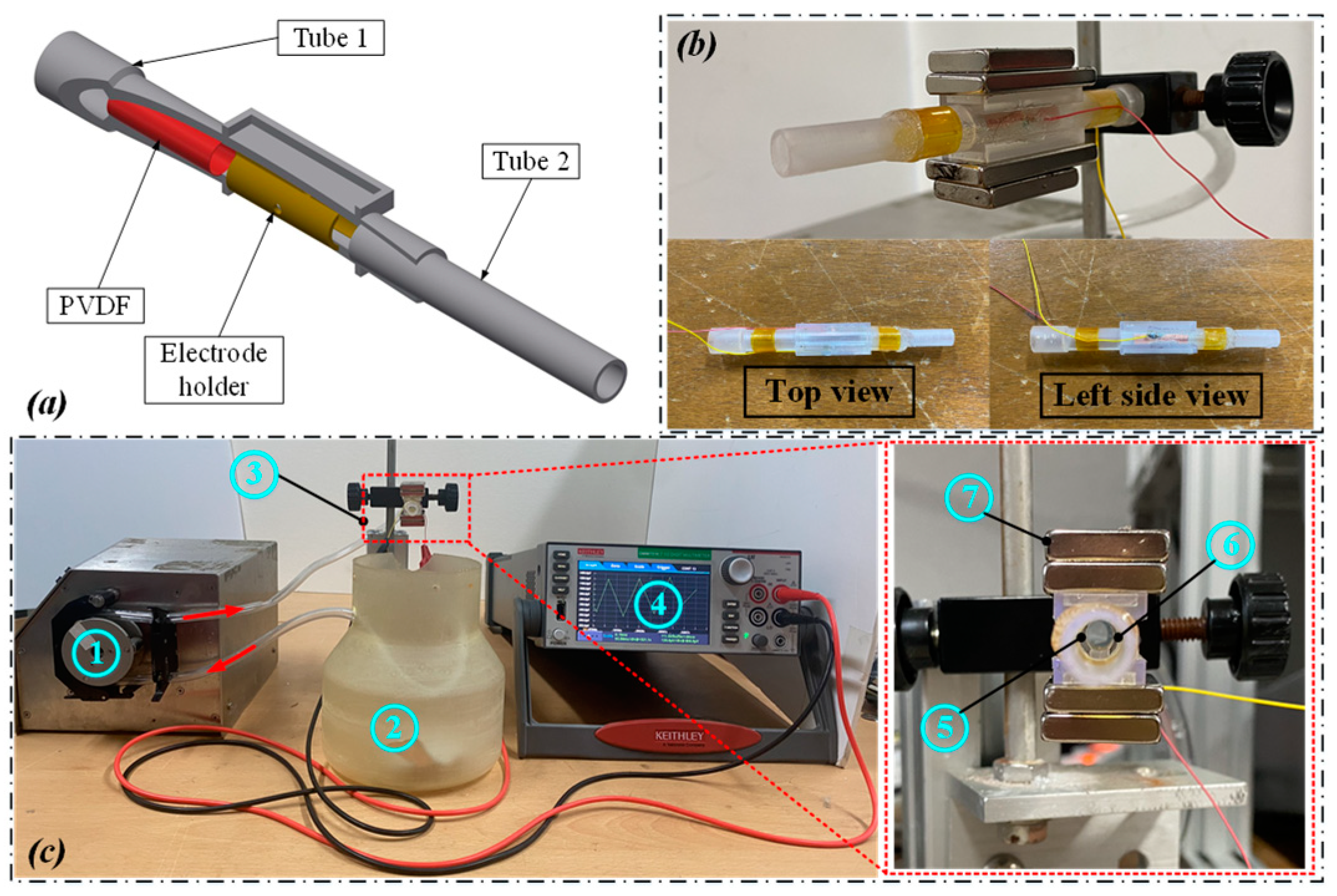
Figure 1. (a) Theoretical design. (b) The actual Mag-TENG. (c) Experimental setup of the Mag-TENG device. Setup includes (1) peristaltic pump, (2) water tank, (3) Mag-TENG tube, (4) electrometer, (5) small electrode, (6) large electrode, and (7) magnet.
Energies 16 04779 g001
Figure 2. (a) The working principle of the Mag-TENG without magnets. (b) The output current from the TENG. (c) The four states of the working principle of the Mag-TENG without the magnetic field effect and a magnified view of a single cycle. (d) The Mag-TENG’s electrical circuit equivalent during operation.
Energies 16 04779 g002
Figure 3. The working principle of the Mag-TENG when applying a magnetic field. The ellipse is the magnetic field region with the direction of movement from the inside to the outside.
Energies 16 04779 g003
Figure 4. (a) The output current and voltage levels from the Mag-TENG using pipe D2 and a flow rate of 390 mL/min with and without a magnetic field strength of 360 mT; 3D graphs of the output current and voltage when varying both the magnetic field strength and the flow rate in (b) pipe D1 (6.5 mm diameter) and (c) pipe D2 (10 mm diameter).
Energies 16 04779 g004
Figure 5. (a) A schematic diagram of the magnetic field direction. (b) The experimental setup for adjusting the magnetic field angle. (c) The experimental results at 0° and 90°, and (d) comparison of the output current and voltage values corresponding to the magnetic field direction with pipe D1. Comparison of (e) the output current and (f) the output voltage of the Mag-TENG with seawater or DI water at the flow rate 650 mL/min in pipe D1 while varying the magnetic field strength.
Energies 16 04779 g005
Figure 6. (a) The output current and (b) the output voltage of the Mag-TENG on pipe D1, (c) current, and (d) voltage on pipe D2, depending on the NaCl concentration inside the seawater.
Energies 16 04779 g006
Disclaimer/Publisher’s Note: The statements, opinions and data contained in all publications are solely those of the individual author(s) and contributor(s) and not of MDPI and/or the editor(s). MDPI and/or the editor(s) disclaim responsibility for any injury to people or property resulting from any ideas, methods, instructions or products referred to in the content.