Review

A Comprehensive Review of Degradation Prediction Methods for an Automotive Proton Exchange Membrane Fuel Cell

1
Department of Mechanical Engineering, Graduate School, Chungnam National University, 99 Daehak-ro, Yuseong-gu, Daejeon 34134, Republic of Korea
2
Department of Clean Fuel and Power Generation, Korea Institute of Machinery & Materials (KIMM), 156 Gajeongbuk-ro, Yuseong-gu, Daejeon 34103, Republic of Korea
3
School of Mechanical Engineering, Chungnam National University, 99 Daehak-ro, Yuseong-gu, Daejeon 34134, Republic of Korea
*
Author to whom correspondence should be addressed.
Energies 2023, 16(12), 4772; https://doi.org/10.3390/en16124772
Submission received: 25 April 2023 / Revised: 8 June 2023 / Accepted: 15 June 2023 / Published: 16 June 2023
(This article belongs to the Special Issue Research in Proton Exchange Membrane Fuel Cell)

Abstract

:
Proton exchange membrane fuel cells (PEMFCs) are an alternative power source for automobiles that are capable of being cleaner and emission-free. As of yet, long-term durability is a core issue to be resolved for the mass production of hydrogen fuel cell vehicles that requires varied research in the range from sustainable materials to the optimal operating strategy. The capacity to accurately estimate performance degradation is critical for developing reliable and durable PEMFCs. This review investigates various PEMFC performance degradation modeling techniques, such as model-based, data-driven, and hybrid models. The pros and cons of each approach are explored, as well as the challenges in adequately predicting performance degradation. Physics-based models are capable of simulating the physical and electrochemical processes which occur in fuel cell components. However, these models tend to be computationally demanding and can vary in terms of parameters between different studies. On the other hand, data-driven models provide rapid and accurate predictions based on historical data, but they may struggle to generalize effectively to new operating conditions or scenarios. Hybrid prediction approaches combine the strengths of both types of models, offering improved accuracy but also introducing increased computational complexity to the calculations. The review closes with recommendations for future research in this area, highlighting the need for more extensive and accurate prediction models to increase the reliability and durability of PEMFCs for fuel cell electric vehicles.

1. Introduction

1.1. Generality

The rising demand for worldwide energy and the negative impact of using fossil fuels on the environment has prompted the development of renewable and environmentally friendly energy solutions. One potential solution is the hydrogen economy, which generates, stores, and converts hydrogen from renewable sources into electricity [1]. Fuel cell vehicles (FCVs) are crucial for achieving low-carbon transportation in the hydrogen economy, and utilizing renewable sources to produce hydrogen is expected to significantly reduce greenhouse gas emissions [2]. Proton exchange membrane fuel cells (PEMFCs), with their low emissions, high efficiency, and low operating temperature, have recently gained popularity as a potential power source for the automotive sector. Although FCVs have been running the road recently, the durability issue associated with performance degrading, which refers to a permanent drop in voltage or power during the long-term operation of PEMFCs, is still the main challenge. It must be solved to achieve worldwide commercialization [3].
PEMFCs integrated into vehicles, in contrast to stationary power plant sources, must meet more strict durability limitations, as fuel cells’ durability may worsen under extreme operating conditions such as sub-zero temperatures, dynamic load variations, and vibrations and shocks. Even though fuel cell deterioration is inevitable over prolonged use, the degradation gradient must be enhanced to make hydrogen fuel cell cars economically feasible [4].
As a system analysis tool, the performance degradation model is essential for health assessment and prognostics. Several tools have been introduced which may be grouped into three main groups: physics-based models, data-driven models, and hybrid models. Physics-based models primarily incorporate fundamental physical laws to explain the degradation process and gain insights into the main causes of failure. On the other hand, data-driven models employ historically collected data to create a model that can describe or predict the degradation process of the system under consideration. The hybrid model integrates both the physical-based and data-driven approaches, leveraging the strengths of both methodologies.
Until now, there have been numerous reviews conducted on the advancements of modeling PEMFC performance [5], degradation indexes [6], physics-based and data-driven models for real-time control [7], data-driven models for fault diagnosis [8], and degradation modeling and lifetime prediction [9,10]. Additionally, some reviews have explored the degradation of specific components such as gas diffusion layers [11], proton exchange membranes [12,13], catalyst layers [14], and membrane electrode assembly [15]. However, there have been relatively few reviews that have specifically addressed degradation modeling in automotive applications. Therefore, this paper provides a comprehensive review of the current status and future development, as well as the challenges and perspectives, of performance degradation modeling of automotive PEMFC systems.

1.2. PEMFC System in Hydrogen Fuel Cell Vehicle

A hydrogen fuel cell vehicle is an electric vehicle that usually produces electricity from PEMFCs. In a pure fuel cell powertrain, the fuel cell is directly connected to an electric motor, which drives the vehicle’s wheels. The fuel cell system is paired with a battery or supercapacitor in a hybrid fuel cell powertrain. At high demand, such as acceleration or hill climbing, the energy storage system supplies extra power to the electric motor. While not in use, such as when cruising or braking, the fuel cell system recharges the energy storage system. Both pure and hybrid fuel cell powertrains offer benefits and drawbacks. Pure fuel cell powertrains are efficient and emit no pollutants, but they are costly and have a limited operating range. Hybrid fuel cell powertrains deliver greater power and range but are more complicated and may need more maintenance.
The PEMFC system, the heart of FCV, comprises a fuel cell stack and auxiliary systems, including fuel supply, air supply, and thermal management systems. The fuel supply system feeds the hydrogen to the anode. The air supply system provides compressed air to the cathode. A cooling system removes the produced heat and releases it into the environment to maintain the desired temperature.
As shown in Figure 1, a fuel cell stack consists of many individual fuel cells connected in series. The heart of each fuel cell is membrane electrode assembly (MEA). In the MEA, a polymer electrolyte membrane (PEM) separates the anode and cathode sides of the fuel cell. A catalyst and gas diffusion layers are attached on each membrane side. The catalyst layer comprises platinum nanoparticles, which aid the electrochemical processes which take place in the fuel cell. The GDL aids in uniform fuel and air distribution throughout the catalyst layer. Gaskets are utilized to establish a seal around the MEA and prevent gas leakage when assembling individual fuel cells into a fuel cell stack. Bipolar plates are also used to sandwich the individual fuel cells, enabling gaseous fuel and air to pass through the stack and transfer electrons between adjacent cells.

1.3. Performance Degradation of the PEMFC System

As mentioned earlier, fuel cell degradation during long-term operation is unavoidable. Researchers have identified several factors which contribute to fuel cell degradation, including platinum-particle dissolution and sintering, carbon-support corrosion, membrane thinning, and bipolar plate corrosion [17]. Understanding the causes of PEMFC system failures allows end users to evaluate the system performance and extend its useful life. The degradation phenomenon may be divided into three categories: mechanical degradation, thermal degradation, and chemical/electrochemical degradation.
  • Mechanical degradation: Fuel cells often fail, and this is attributable to material defects and poor structural design and manufacture. Material flaws may generate non-uniform mechanical stresses, fractures, and premature failure. Material flaws, improper structural design, and manufacturing errors produce non-uniform mechanical stresses and fractures. Operating conditions may affect fuel cell components’ physical qualities. Membranes, catalyst layers, etc., shrink or swell depending on the temperature. The non-uniform pressure distribution on components resulting from the cathode-anode pressure difference causes mechanical damage. High and non-uniform mechanical stresses may perforate or shred interfaces between components during cell or stack assembly [9,17].
  • Thermal degradation: The fuel cell operating outside the temperature range induces structural changes [18]. PEMFCs work well at 60–80 °C. The glass transition of PFSA polymers causes the severe destruction of conventional Nafion-type membranes around 80–120 °C [19]. One requirement for PEMFCs in automotive applications is the capacity to start at subfreezing temperatures. Notably, in automotive applications, the Department of Energy requires PEMFC stacks and systems to start up and operate at −20 °C to 50% rated power in 30 s using less than 5 MJ of energy [20]. However, the formation and melting of ice during long-term operation at subfreezing temperatures could delaminate the MEA and gas diffusion layers [17].
  • Chemical/electrochemical degradation: This is mainly caused by the material’s natural aging, including Pt dissolution and carbon support corrosion/oxidation in the catalyst layers (CLs) and gas diffusion layers (GDL), radial attack in the membrane, and bipolar plate (BBP) corrosion [9]. In addition, contaminants in the fuel and oxidation sources, such as CO, H2S, NH3, etc., may induce catalyst toxicity and affect the catalytic activity, diffusion, and hydrophobic properties [17].

1.4. End-of-Life Definition/Criterion

The end-of-life (EoL) criteria for fuel cells are not consistently used in the literature. There are no EoL criteria that are widely followed, particularly for automobile applications. The most used definition for EoL was created by the US Department of Energy (DOE), which targets 10% voltage degradation [9,21]. This criterion works well for static conditions of current but not load changes [21]. Fuel cells in automobiles provide drive cycle power. In such cases, using the power to define the EoL appears to be better. EoL occurs when the fuel cell cannot provide the power that is required [22]. An EoL threshold could be set. However, it would rely strongly on the system designer [21]. The Fuel Cell Testing and Standards Network established another EoL criterion (FCTESTNEST), a pre-defined minimum value of the fuel cell voltage. If the voltage drops below the threshold value of 0.3 V, the durability test stops [17].

1.5. Classification of Degradation Modeling Methods

A performance degradation model forecasts the PEMFC performance deterioration during operation. Modeling the performance degradation of PEMFCs is necessary to predict their state of health (SOH) and remaining useful life (RUL). Degradation modeling methods can be classified into two main approaches: model-based and data-driven methods, as seen in Figure 2. In addition, the hybrid approach combines the model-based and data-driven methods based on their advanced features.
  • The model-based method predicts the aging process using mathematical equations. This method does not need a large amount of data. However, it may be computationally expensive, and model construction may be tricky.
  • The data-driven method uses collected data to understand the system’s behavior. It detects non-linearities without a degradation model. However, it demands a large amount of data to perform prognostics.
  • The hybrid method enhances model learning and improves model uncertainties. However, it may be challenging to design and computationally costly.
This paper contributes to a detailed and critical assessment of the performance degradation modeling methodologies of PEMFC systems, focusing on automotive applications. The project will first focus on PEMFC degradation modeling approaches. Then, the challenges and prospects will be discussed. This review paper aims to be a helpful resource for researchers and engineers with regards to fuel cell technology for automotive applications.

2. Performance Degradation Modeling of PEMFC

2.1. Model-Based Approach

As noted earlier, the model-based approach does not need much data. However, it is necessary to have an in-depth knowledge of the processes associated with the aging of PEMFCs. This might be a substantial drawback, as PEMFC aging mechanisms are not yet completely understood [10]. Model-based approaches typically rely on the system’s physical equations, which can take several forms, including mechanistic degradation, empirical, and semi-empirical models. The mechanistic degradation model describes the degradation mechanisms using physical fuel cell equations. The empirical models use just experimental data and statistical analysis. Semi-empirical models combine physical understanding with empirical data.

2.1.1. Mechanistic Degradation Model

a.
Membrane Degradation Mechanism Model
Membrane failure may lead to hydrogen leakage and the ultimate breakdown of the whole cell. Chemical and mechanical processes are the two primary mechanisms of membrane degradation. Futter et al. [23] created a model based on physics that describes the membrane’s chemical degradation. This model incorporates the generation of and reduction in hydrogen peroxide, the redox cycle of iron impurities in the ionomer phase, radical formation resulting from Fenton’s chemistry, and radical attack on the polymer structure. Ferreira et al. [24] developed a submodel for membrane chemical degradation that concentrates on the attack mechanisms of •OH and •OOH. This submodel was then added to a computational fluid dynamics (CFD) code to estimate the overall membrane degradation and uneven distribution of degradation over the MEA surface. Singh et al. [25] developed a transient chemical degradation model to investigate the effect of membrane degradation on PEMFC performance. In this study, the model explains membrane degradation in two stages. The first stage includes the indirect formation of hydroxyl radicals. In contrast, the second stage involves a four-step attack of the hydroxyl radical at the terminal ether bond on the side chain, the ether bond close to the main chain, chain scission at the side chain, and chain unzipping. Hasan et al. [26] proposed a numerical technique for predicting the lifespan and degradation of reinforced membranes in PEMFCs, concentrating on mechanical fatigue failure as a typical degradation process that might lead to PEM failure. Hydration-induced mechanical forces, which occur cyclically, initiate and intensify membrane cracking. Zhou et al. [27] recently developed a computational model to simulate gas penetration across blistered PFSA membranes, taking into account the material characteristics and the solution-diffusion process. The Gurson damage model is also included in the model to account for the increase in gas permeability caused by mechanical deterioration. The model was evaluated using blister and gas permeation testing data and increases in gas permeability were predicted with high accuracy. The researchers also investigated the effect of non-uniform deformation and mechanical damage on gas permeability.
b.
Catalyst layer degradation mechanism model
The loss of electrochemical active surface area (ECSA) due to catalyst degradation is a significant factor which contributes to the performance degradation of PEMFCs. Zhang and Pisu [28] created a catalyst degradation model based on Darling and Meyers’ platinum dissolution kinetic models [29] to assess fuel cell damage. The effects of the operating conditions on the electrochemical surface area (ECSA) loss rate were also investigated. The model evolved from investigating the underlying principle of catalyst degradation and assessing the interaction behavior of multi-group catalyst particles and particle size distribution. The model was then applied using an unscented Kalman filter (UKF) technique to evaluate the ECSA loss during the fuel cell operation. Li et al. [30] suggested a Pt degradation model in the cathode catalyst layer (CCL) based on Holby and Morgan’s thermo-kinetic model of Pt degradation [31]. The model includes two Pt degradation mechanisms: Ostwald ripening on carbon support and Pt dissolution-re-precipitation through the ionomer phase. With the capacity to forecast the impacts of temperature and humidity on ECSA loss, the proposed model is suitable for integration into a comprehensive fuel cell model that includes electrochemistry, water and heat management, and durability. Polverino and Pianese [32] developed a model that describes the degradation of the electrochemical active surface area (ECSA) due to catalyst dissolution and Ostwald ripening mechanisms in the CCLs of PEMFCs. This proposed model was then employed to estimate the voltage degradation rate of PEMFCs. Koltsiva et al. [33] presented a mathematical model that considers various mechanisms that are responsible for the degradation of the electrochemical active surface area (ECSA) in the catalyst layers of PEMFCs. These mechanisms include platinum nanoparticles’ electrochemical dissolution, particle growth due to Ostwald ripening, the migration of nanoparticles along the carbon support, the coalescence of fine particles, and the diffusion of platinum ions in the ionomer. It is the first time that various degradation processes have been integrated into a single mathematical degradation model. Jahnke et al. [34] created a 2D Pt degradation model to evaluate the aging of the cathode catalyst layer. The aging phenomena of Pt particles, such as oxidation, dissolution, Ostwald ripening, and band formation near the membrane, were included in this model. The effects of the steady-state and load-cycling conditions on the degradation were investigated. The results showed that degradation was more severe under load cycling conditions. Jahromi et al. [35] suggested a novel method for studying the deterioration of the catalyst layer in a PEM fuel cell under cyclic load using Ansys Fluent software. The model calculates the degradation of the ECSA, the development of Pt particles, the creation of agglomerates by Ostwald ripening, and the loss of Pt mass loading. Pt degradation in a PEMFC, including Pt mass loss and Ostwald ripening mechanisms, was also modeled by Zheng et al. [36]. Currently, the theorical models which assess the local transport resistance associated with the permeation and diffusion of oxygen molecules in the ionomer film covering the Pt surface, which is considered as a crucial issue in the current-generation efficiency of Pt in ultralow-Pt CL, were provided by Tang et al. [37]. The oxygen local transport resistance decreases when lowering Pt loading, owing to that the thinned CCL amplifies the electrochemical contribution of the PEM|CCL interface, which results in an increased active area and consequent higher mass activity of Pt [38]. Although the above models could predict ECSA degradation and the voltage degradation of PEMFCs accurately, it is essential to note that ECSA loss is not the only factor that contributes to fuel cell degradation. Other aging parameters should also be considered to fully capture the degradation phenomena in a fuel cell stack.
c.
GDL degradation mechanism model
As an essential part of PEMFCs, the gas diffusion layer (GDL) supports the cell mechanically and affects the mass, heat, and electron transfer. The primary cause of GDL degradation is the loss of hydrophobicity, which is attributable to polytetrafluoroethylene (PTFE) degradation, a common material utilized in the fabrication of GDLs that helps to give hydrophobicity to the GDL surface [39]. In addition, the content of PTFE affects the gas permeability of the GDL [40]. Seidenberger et al. [41] used a three-dimensional Monte Carlo model to investigate the influence of polytetrafluoroethylene (PTFE) degradation on the behavior of water accumulation within the gas diffusion layer (GDL) of a fuel cell. The results revealed that, when the PTFE covering was decreased, the water content inside the GDL increased, producing larger water clusters. This is because a reduction in PTFE coverage leads to decreased hydrophobicity on the GDL surface, allowing more water to accumulate in the GDL. Furthermore, when the PTFE coverage was lowered to a value of 55 percent, substantial water clusters developed, covering the whole surface of the GDL. This can significantly accelerate the aging of the GDL, which can negatively impact the performance and lifespan of the fuel cell. Pauchet et al. [42] provided a computational technique to examine the impacts of hydrophobicity loss on the GDL gas diffusion coefficient. This approach involves combining pore network modeling and performance modeling. The pore network model was used to determine the gas diffusion coefficient. The results obtained by the computational model showed good agreement with the experiment.
d.
Summary of mechanistic degradation models
Various studies have reported the development of mechanistic degradation models. The benefits of employing mechanistic degradation models include the requirement of less training data and their ability to generalize well. As the aging time changes, users can observe the changes in both the internal state and crucial parameters of PEMFCs, simultaneously. However, the major drawback is the complexity involved in constructing an accurate mechanistic degradation model, as it requires a profound understanding of PEMFC degradation mechanisms. Certain degradation mechanisms in PEMFCs remain ambiguous, and certain model parameters must be determined solely through experimental data or expert knowledge. All of these factors contribute to the challenge of establishing a mechanistic degradation model for PEMFCs.

2.1.2. Empirical Model

a.
Model development
The empirical degradation model for PEMFCs is a model-based method that uses linear or exponential equations to describe the degradation of PEMFCs based on historical data. Pei et al. [43] presented an empirical equation for fuel cell lifetime relating to load-changing cycles, start–stop cycles, idling time, high power load conditions, and the air pollution factor. The model equation is as follows:
T f = P k p P 1 n 1 + P 2 n 2 + P 3 t 1 + P 4 t 2
where ΔP stands for the limited decreased value of the fuel cell performance from beginning to the lifetime end according to its definition; kp is the accelerating coefficient; P 1 , P 2 , P 3 , and P 4 are performance deterioration rates resulting from large-range load change cycling, start–stop cycling, and idle condition and high power load condition separately, measured in laboratory; n1, n2, t1, and t2 are load changing cycle times, start–stop cycle times, idle time and high power load time per hour, gained from the vehicular driving cycle.
The proposed empirical model was utilized to investigate the impact of various loading modes on the RUL of a fuel cell bus system. The results showed that dynamic load and startup/shutdown modes significantly contributed to PEMFC degradation and performance loss, accounting for 56.5% and 33%, respectively. In contrast, high power and idling load modes had smaller contributions of 5.8% and 4.7%, respectively. This suggests that dynamic load and startup/shutdown modes are crucial to performance losses. Chen et al. [44] employed the empirical model proposed by Pei et al. [43] for rapidly assessing the lifespan of PEMFCs in vehicles. The researchers expanded upon this method to create a residual life prediction technique that improves the accuracy of fuel cell lifespan estimation and estimates the remaining lifespan.
Jouin et al. [45] developed a particle filter (PF)-based prognostics approach for PEMFCs. Three empirical aging models were proposed: linear, exponential, and logarithmic. These models, using PEMFC experimental data, are subjected to static and dynamic loads. According to the authors, the logarithmic model (represented by Equation (2)) provided the most accurate predictions. Despite promising results, the models were too simplistic to account for disturbances encountered during aging. In [46], Jouin et al. further improved their previous works, published in [45], by introducing a model for coefficient a, which evolves with time. The models for a, b, and voltage recovery models are shown in Equations (3)–(5). They used these models in a joint particle filter framework, leading to better estimations of power behavior during stack aging. Compared to the prior model, the improved model reflected the power’s behavior more accurately during stack aging.
P t = a · ln t b · t + c
where P (t) is stack power evolution through time; a and c are model coefficients; b is a coefficient driving the speed of degradation.
a t = a 1 exp a 2 · t + a 3 exp a 4 · t
b t = b 1 exp b 2 · t + b 3
R e c t = r 1 exp r 2 · t + r 3 exp r 4 · t
Chen et al. [47] also proposed three empirical voltage degradation models, including line, exponential, and logarithmic models, combined with the unscented Kalman filter (UKF) to accurately estimate the degradation of PEMFCs. The authors validated and compared the accuracy of three models with the data of postal fuel cell electric vehicles under actual road conditions. According to the results, the logarithmic model, represented by Equation (6), provides more accurate deterioration estimations than the linear and exponential models.
x k = x k 1 α β ln k k 1 + Q k 1
where xk represents the PEMFC voltage at the sampling step k, the empirical coefficient α is related to the voltage degradation rate of PEMFC under constant load and operating conditions, and the empirical coefficient β is related to the voltage degradation rate of the PEMFC under variable load and special operating conditions.
Wang et al. [48] analyzed five-cell stack degradation as a stochastic process using state space equations (Equations (7) and (8)). Stochastic fusion filtering from various sensors can estimate the degradation status. An inverse Gaussian function was used to calculate the RUL distribution. The estimated results suggest that stochastic fusion filtering improves prognostics accuracy in comparison to single-sensor filtering.
X k + 1 = X k + η T + σ B k
Y k = H X k + v k
where Xk is a five-cell degradation dataset at time tk, Yk is the sensor’s value at time tk.
T = t k t k 1 , X k = x k 1 ; x k 2 ; x k 3 ; x k 4 ; x k 5 , x k 1 is the actual degradation state of the first cell at time t k . Y k = y k 1 ; y k 2 ; y k 3 ; y k 4 ; y k 5 , y k i (i = 1–5) is the monitoring data about the cell i at time t k , η = η 1 , η 2 , η 3 , η 4 , η 5 is a drift coefficient vector-, σ = σ 1 , σ 2 , σ 3 , σ 4 , σ 5 is the diffusion coefficient to restrict Bk, B k = B k 1 , B k 2 , B k 3 , B k 4 , B k 5 represents the random part driven by Brownain motion, v k = v k 1 , v k 2 , v k 3 , v k 4 , v k 5 , and H is a matrix of five rows and six columns. The superscript Arabic numerals represent the parameter of the nth component.
b.
Summary of empirical degradation models
Various studies have documented the development of the degradation models for PEMFCs that are listed in this review. The majority of the empirical models aim to create a straightforward mathematical representation of the degradation rate of voltage or power as a function of time. These models rely on curve fitting techniques to determine the empirical coefficients using experimental data. Empirical degradation models offer benefits such as simplicity, low computational requirements, and ease of implementation. However, when compared to mechanistic degradation models, they suffer from lower precision and limited applicability. Furthermore, empirical degradation models necessitate a larger amount of experimental data to identify the model parameters.

2.1.3. Semi-Empirical Model

a.
Model development
A semi-empirical PEMFC performance degradation model using a combination of a physics-based performance model and degradation formulas derived from experimental data using curve-fitting techniques is described below. The most-used modeling framework for prediction is electrochemical empirical models, which are computationally inexpensive, as shown in Equation (9) [11]. The potential calculated in Equation (9) must be multiplied by the number of cells to extend the model to the stack level.
V = E r e v η a c t η o h m η c o n
where Erev is the Nernst potential; ηact, ηohm, and ηcon, respectively, represent the activation overvoltage, ohmic overvoltage, and concentration overvoltage.
Jouin et al. [49] developed an aging model incorporated with the PF framework to assess PEMFC health. Based on the fuel cell voltage equation in [50], the aging factors were chosen and substituted with time-dependent expressions. The global expression of the stack power degradation is shown in Equation (10). The initial parameters were determined by fitting a model to experimental polarization curve data at t = 0 using the least squares approach. Power degradation data determined the aging parameters. In this model, most time-dependent aging parameters were linear, while others were logarithmic.
P I , t = n I t [ E r e v R T 2 α a F ln i l o s s , 0 e b l o s s t + I t A 0 e b A 1 t + A 1 e b A 2 t i 0 , a R T 4 α a F ln i l o s s , 0 e b l o s s t + I t A 0 e b A 1 t + A 1 e b A 2 t i 0 , c I t A 0 e b A 1 t + A 1 e b A 2 t R i o n , 0 · e b i o n t + R 0 + b R t     ( b c , j + b B t ) ln 1 I t A 0 e b A 1 t + A 1 e b A 2 t 4 F R T D O 2 , j + b D t L G D L P O 2 ] p
where:
  • Erev is reversible cell voltage.
  • R is gas constant equal to 8:3145 J·mol−1·K−1.
  • n is cell number.
  • T is stack temperature.
  • αa and αc are the charge transfer coefficients at the anode and at the cathode.
  • iloss,o represents the initial internal currents within the stack.
  • bloss is the aging rate parameter of iloss,o.
  • i0a and i0c are the exchange current densities at each electrode.
  • Rion,o is the initial ionic resistances.
  • bion is the aging rate parameter of Rion,o.
  • Ro represents for both electronic and contact resistances.
  • bR is aging rate parameter of Ro.
  • Bc is an empirical parameter allowing taking into account the effect of water and gas accumulations leading to non-uniform current densities on the electrode.
  • DO2 is the diffusivity of oxygen.
  • bD is aging rate parameter of DO2.
  • I(t) is the time-dependent current.
  • A(t) is the active area of the electrode that decreases with the aging given by an exponential form.
A t = A o exp b A 1 t + A 1 exp b A 2 t
Zhou et al. [51] proposed a similar degradation model based on a multi-physics aging model using the prognostic framework (PF) and an extrapolation approach. The multi-physics aging model includes activation, ohmic, and concentration losses. The aging dataset is split into learning and prediction phases. During learning, the PF framework studies the degradation and updates the aging parameters. In the prediction phase, curve-fitting functions that match the deterioration patterns of the learned aging parameters are utilized to estimate future values. This approach yields good results, although operational conditions affect its accuracy. A prediction method based on fitting curves requires changes in the proper functions when the operational conditions change.
Bressel et al. [52] proposed a simpler aging model than the model proposed by Jouin et al. [49]. The model uses a similar general polarization curve equation, but only two parameters (ohmic resistance and limiting current) are considered to change over time. The change in the resistance and the current limit are linked with the single parameter α, as expressed in Equation (11).
E = E r e v R o 1 + α t i A T l n i i o B T l n 1 i i L , o 1 α t
where α(t) = βt and β is a constant.
  • Erev is reversible cell voltage.
  • i is operating current density.
  • T is fuel cell temperature.
  • Ro is initial total resistances of fuel cell.
  • A is the Tafel constant.
  • B is a concentration constant.
  • iL,o is initial limiting current density.
  • io is exchange current density.
Similarly, Yue at al. [53] established a unique time-varying variable α(t) to reflect the state of health of the fuel cell in dynamic operation. In this model, α(t) was chosen to describe the deviation in the equivalent resistance (Req) and exchange current (io), as shown in Equation (12).
E = E r e v R e q , o 1 + α t i A T l n i i o , o 1 α t B T l n 1 i i L , o
where R e q , o and i o , o are initial equivalent resistance and exchange current density.
Wang et al. [54] proposed the state space model to describe the degradation process of PEMFCs as expressed in Equation (13). In this model, a polarization resistance, which represents the sum of all of the polarization losses in fuel cells, was introduced.
V = E r e v R o 1 + α t i A T l n i i o B T l n 1 i i L , o + ε t                
where α t = α t 1 + ω t 1   is the degradation degree of the polarization resistance, R*. The ω and ε are the process and observation noises.
  • Erev is reversible cell voltage.
  • i is operating current density.
  • T is fuel cell temperature.
  • R*o is initial a polarization resistance.
  • A is the Tafel constant.
  • B is a concentration constant
  • iL,o is initial limiting current density.
  • io is exchange current density.
Bressel et al. [55] progressed the previous work [52] by including an uncertainty quantification in the model for PEFC RUL prediction under a variable load. The presented model can perform prognostics for PEFCs running a micro-CHP load profile without degradation speed information. For automotive applications, the load profile is far more dynamic and requires a faster convergence time, for which the model is not well adapted. Zhang et al. [56] presented a quasi-static model based on the PF method to predict the degradation of PEMFCs. The degradation of the open circuit voltage E and the internal resistance R were coupled by one variable γ(t), as shown in Equation (14). The proposed method shows promising results, but it should be noted that the model only considers one degradation coefficient, which may not fully capture all performance losses.
V = E r e v , o 1 γ t R o 1 γ t A · ln i i o m 1 exp m 2 i
where:
  • Erev is reversible cell voltage.
  • R is internal resistance.
  • A is Tafel constant.
  • i is operating current density.
  • io is exchange current density.
  • m1 and m2 are the mass-transfer constants.
L. Mao et al. [57] proposed a PF-based degradation model to estimate PEMFC internal behavior evolution and forecast fuel cell performance using polarization curves at different times. In this model, the anode activation voltage loss was ignored as it is negligible compared to cathode overvoltage. The parameters in Equation (15) were derived by matching the polarization curves at different times. The results from this study suggest that fuel cell performance can be reliably predicted in both steady-state and dynamic conditions.
V i , t = E r e v R T 2 α F ln i a 1 a 2 t R T 2 α F ln b 1 + b 2 t a 1 a 2 t i c 1 + c 2 t d 1 e d 2 t exp i · e 1 e e 2 t
where:
  • Erev is reversible cell voltage.
  • T is fuel cell temperature.
  • α is the charge transfer coefficient.
  • R is gas constant equal to 8:3145 J·mol−1·K−1.
  • i is operating current density.
a1, b1, and c1 are the initial values for ioc (exchange current density at cathode), in the internal current density and Rmem (membrane resistance), respectively; a2, b2, and c2 represent the PEM fuel cell degradation rate due to the activation loss, fuel crossover loss, and Ohmic loss; d1 and e1 control the amplitude of the mass transport loss, while d2 and e2 express the PEM fuel cell degradation rate due to mass transport loss during the operation.
Recently, Wang et al. [58] developed a semi-empirical degradation model which incorporates degradation factors fitted with experimental data into the fuel cell performance formula presented in Equation (16). The model has been validated by showing that the predicted results were in good agreement with experimental data. However, the model does not consider the internal water transport process and internal resistance changes during dynamic load changes, which may affect its accuracy. Nonetheless, despite these limitations, the model’s ability to match experimental data implies that it may still have utility in specific applications. Further studies might be necessary to improve the model’s accuracy by incorporating these factors.
V i , t = E r e v R T 2 α a F ln i + 0.5 i l e a k , 0 exp b l e a k t a E C S A , 0 m P t , a i a , r e f θ T , a c H 2 c H 2 , r e f 0.5 R T 4 α c F ln i + i l e a k , 0 exp b l e a k t a E C S A , 0 exp b E C S A t m P t , c i c , r e f θ T , a c O 2 c O 2 , r e f i R i o n , 0 . e b i o n t K c R T 4 α c F ln 1 i 4 F R T D O 2 , 0 + b D t L G D L P O 2
where:
  • Erev is reversible cell voltage.
  • R is gas constant equal to 8:3145 J·mol−1·K−1.
  • n is cell number.
  • T is stack temperature.
  • αa and αc are the charge transfer coefficients at the anode and at the cathode.
  • i is operating current density.
  • ileak,o is initial leaking current density.
  • bleak is aging rate parameter of ileak,o.
  • ia,ref and ic,ref are referent current density at anode and cathode.
  • Rion,o is the initial ionic resistance.
  • bion is the aging rate parameter of Rion,o.
  • DO2 is the diffusivity of oxygen.
  • bD is aging rate parameter of DO2.
  • Kc is the concentration loss coefficient.
  • aECSA,o is the initial electrochemical active surface area of catalyst layer.
  • bECSA is aging rate parameter of aECSA,o.
  • mpt is Pt loading.
b.
Summary of semi-empirical degradation models
Various studies have reported the development of semi-empirical degradation models for PEMFCs. Taking into account the strengths and weaknesses of mechanism degradation models and empirical degradation models, the semi-empirical models offer the advantage of easy implementation and online performance, making them suitable for on-line applications. They not only ensure the accuracy of the degradation model but also have a low computational burden. Additionally, these models can be utilized to investigate the physical phenomena occurring within a fuel cell. However, it is important to note that the presented models are limited to a quasi-static behavior, which may not be sufficient to fully replicate the dynamic behavior of a fuel cell that is integrated into transportation applications.
The semi-empirical degradation models were formulated based on experimental data, with certain model parameters being determined according to the degradation mechanism of PEMFCs. Parameter determination is an optimization problem that involves finding the best combination of parameters so that the model can accurately describe the collected data. To solve this problem, heuristic search methods such as genetic algorithms (GA), differential evolution (DE), and particle swarm optimization (PSO) have been applied. These methods have different variants and have been used for parameter estimation. For more information about these parameter estimation problems, you can refer to the comprehensive review conducted by M. Ohenoja et al. [59].

2.1.4. Summary

The model-based method uses mathematical equations to understand and make predictions about the PEMFC aging process. This approach has several advantages and disadvantages, which will be outlined below:
Advantages of the model-based approach:
  • Models can easily be implemented and make predictions about the future behavior of PEMFC systems. Simulating the model can be used to explore various scenarios and make informed decisions.
  • Models can provide valuable insights into the relationship and interactions between different components of the PEMFC system.
  • Models can be used to optimize the PEMFC system by identifying the optimal operating conditions.
  • Models do not require a large amount of data. Thus, they can be used to explore different scenarios and hypotheses in online environments before implementing them in real world situations.
  • Disadvantages of the model-based approach:
  • Models require a good understanding of the behavior and degradation mechanisms of fuel cell systems and their components.
  • Creating an accurate and reliable model can be challenging and time-consuming.
  • Models need to be validated and verified against experiment data to ensure their accuracy and reliability.
  • Models may be limited to the specific conditions under which they were developed. Extrapolating model predictions to different conditions may lead to inaccurate results.

2.2. Data-Driven Approach

Instead of depending on physical equations and fuel cell aging mechanisms, the data-driven approach analyzes aging data sets to model and forecast future outcomes. This approach can be useful when the physics-based models are poorly established or too complex to implement. In this method, a black-box model of aging behavior is usually built using algorithms trained on extensive experimental data [60]. Generally, artificial intelligence (AI), statistical, and signal-processing models are the three main types of data-driven models. This section focuses mainly on AI models since statistical and signal-processing models have limited usage in addressing PEMFC degradation. The applications of statistical and signal-processing methods for PEMFC fault diagnosis are comprehensively reviewed by Zheng et al. in [8]. AI models can be divided into four groups: artificial neural network (ANN), fuzzy logic (PL), support vector machine (SVM), and Gaussian process (GP).

2.2.1. Artificial Neural Network (ANN) Model

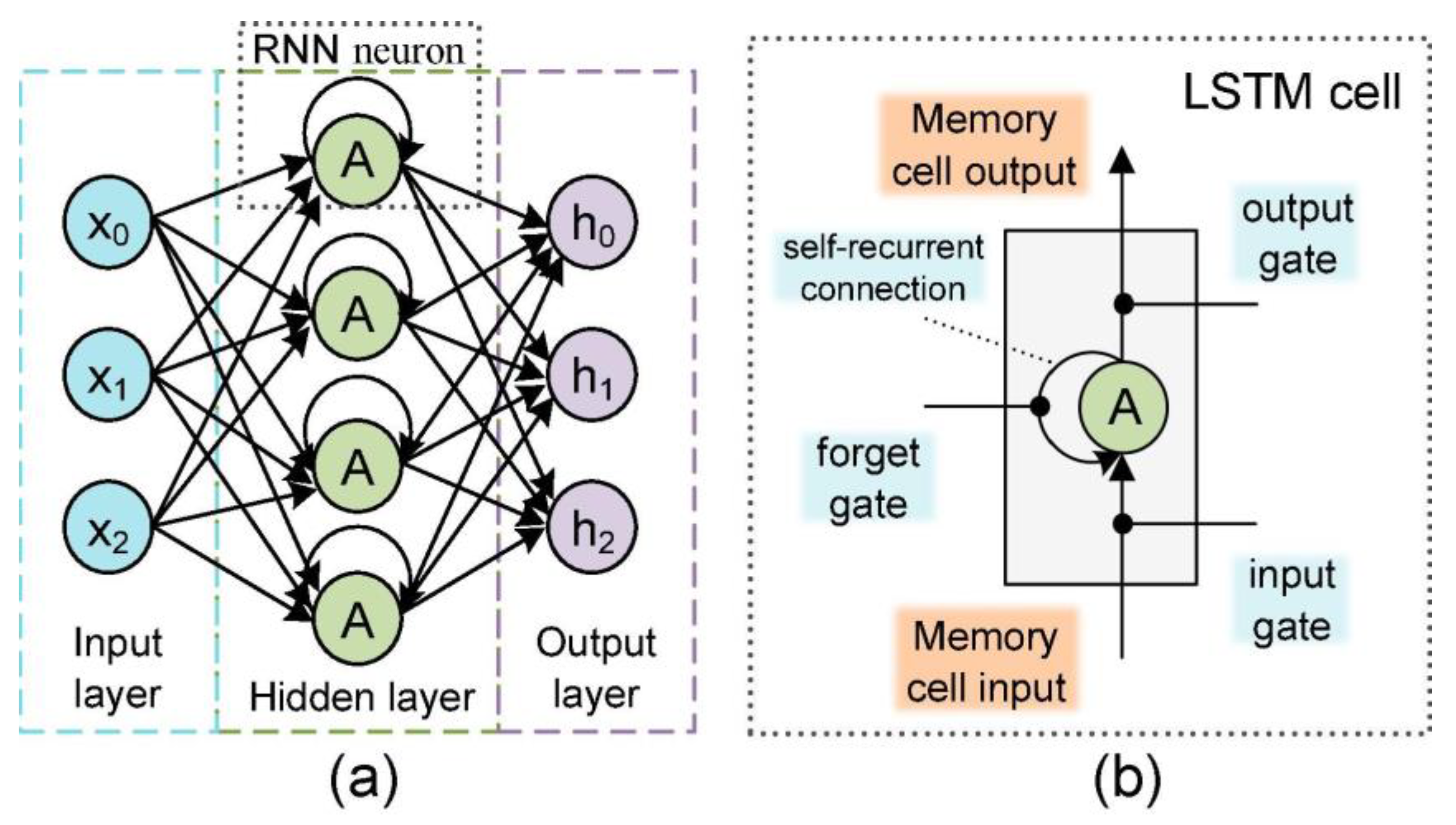
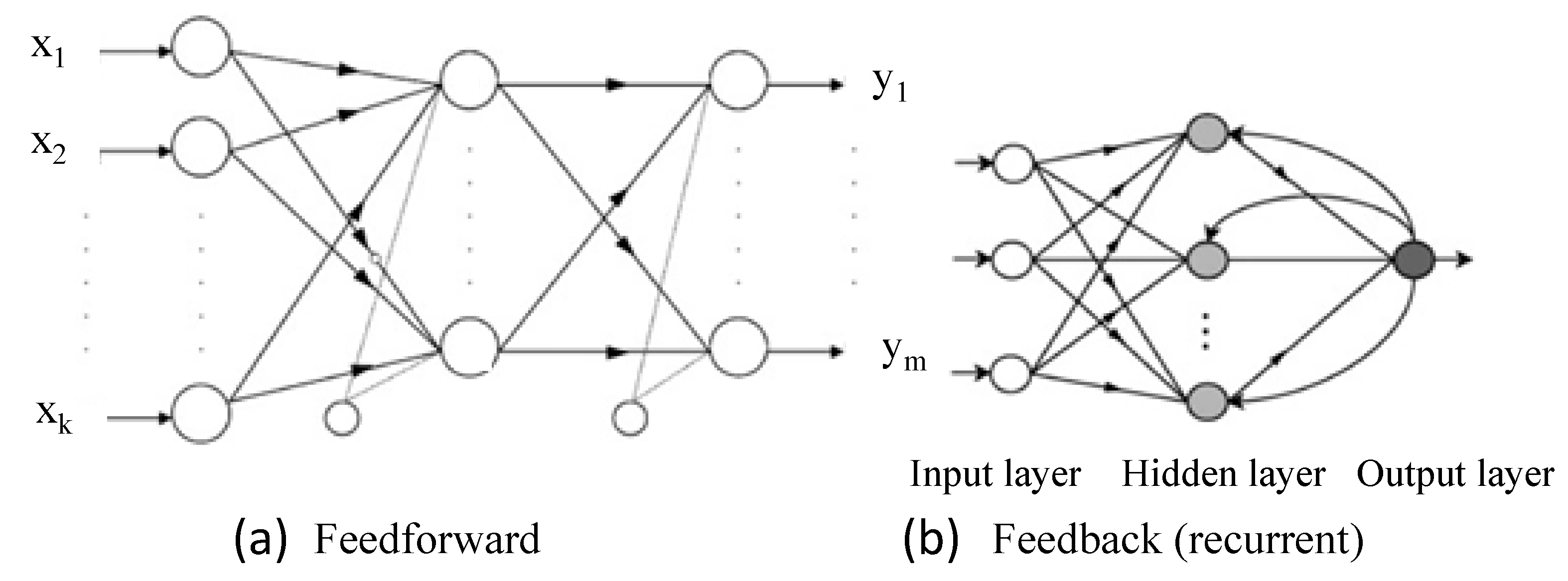
A neural network model learns from given inputs to produce the desired outcome. After learning from historical data, the network model can be used to predict system statuses [61]. The performance of a neural network model depends on several factors, including the topology of the network and the selected input parameters [7]. There are two types of neural network topologies: feedforward (Figure 3a) and recurrent (Figure 3b). The feedforward neural network (FNN) is one of the most basic artificial neural networks. As shown in Figure 3a, all signals only go forward and do not have feedback connections. The functions of the output layers establish the output of the entire network. A recurrent neural network (RNN) refers to a network of neurons with feedback connections, as illustrated in Figure 3b. It stores a layer’s result and feeds it to the input to predict its outcome. Once the first layer output is calculated, the RNN starts. After this layer, each unit will remember information from the previous step to compute as a memory cell. Several types of neural network structures have been presented, including backpropagation neural networks, long-short-term memory (LSTM) neural networks, echo state networks (ESNs), and convolutional neural networks (CNNs).
a.
Back propagation neural network
The back propagation (BP) neural network is an error backpropagation-trained, multilayer feedforward neural network. It learns through both forward propagations, where input data go through the hidden layer and output layer, and backward propagation, where the output error is passed back through the hidden layer, as depicted in Figure 4. Neuron weights and thresholds are then adjusted based on the error signal to approximate the predicted output to the desired output.
Chen et al. [63] employed a BP neural network to predict the aging behavior of PEMFCs. The parameters of the BP neural network model were optimized using an evolutionary algorithm that includes a mind evolutionary algorithm (MEA), particle swarm optimization (PSO), and genetic algorithm (GA). Three aging data sets were employed to verify the model. According to the results, the suggested model can reliably predict PEMFC degradation in various applications. Chen et al. [64] used wavelet analysis and a BP neural network (WNN) to predict the degradation of PEMFCs. Wavelet analysis can examine PEMFC degradation features at different frequencies by changing the wavelet basis function. It can also extract local features of signals by analyzing them at multiple scales. However, the authors pointed out some limitations. The number of hidden layer neurons significantly affects PEMFC degradation prediction, but finding the optimal number is hard. The authors used a cuckoo search algorithm (CSA) to solve these problems. The CSA optimizes weights, wavelet basis function parameters, and hidden layer neuron numbers. Then, CSA-WNN predicts the PEMFC RUL. Figure 5 shows PEMFC degradation prediction based on CSA-WNN. According to research, CSA-WNN outperforms other algorithms in prediction accuracy, including BP, extreme learning machines, RVM, and SVM.
b.
Long-short-term memory neural network
Long-short-term memory (LSTM) neural networks are specialized RNNs. In RNNs, backpropagation may cause vanishing or exploding gradient problems, making network weights too small or too large in applications that need the network to learn long-term relationships [65]. To address these problems, LSTM networks use additional gates to control the data flow into and out of the system’s memory, allowing the network to better learn the long-term relationships in the data [66]. As shown in Figure 6b, an LSTM cell generally consists of a memory cell, an input gate, an output gate, and a forget gate, in addition to the hidden state seen in conventional RNNs (Figure 6a). The architecture of the LSTM memory cell is shown in Figure 7. The data are trained and updated at every time step in a long-term period through the cell state.
R. Ma et al. [65] suggested a new deep-learning model for fuel cell degradation based on RNN with grid-long short-term memory (G-LSTM) based on paralleling and combining individual LSTM cells. Each layer in the G-LSTM cell design has its own hidden state and memory cell, which it utilizes to exchange information with the other layers. This method was tested on different data sets and it was shown that it could predict fuel cell degradation precisely.
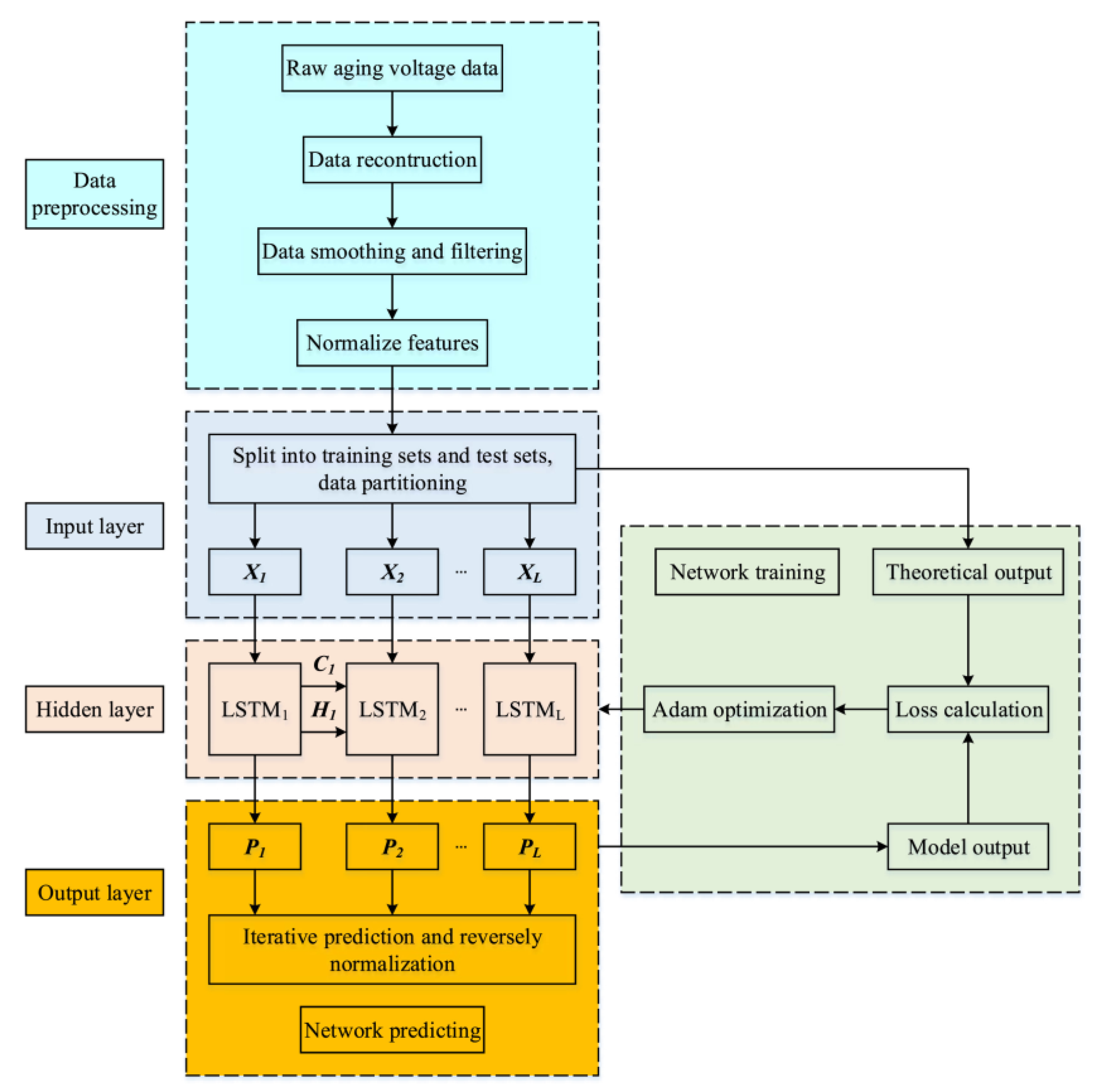
J. Liu et al. [67] established another PEMFC useful life prediction model based on LSTM RNN, as shown in Figure 8. The model was validated by experimental aging data of PEMFCs over 1154 h at static conditions. The data were smoothed using a combination of locally weighted regression discrete smoothing and uniformly spaced sampling. The authors claimed that this method was 28.46% more accurate than a BP neural network. However, the method was only verified for PEMFC lifetime prediction in constant operating conditions.
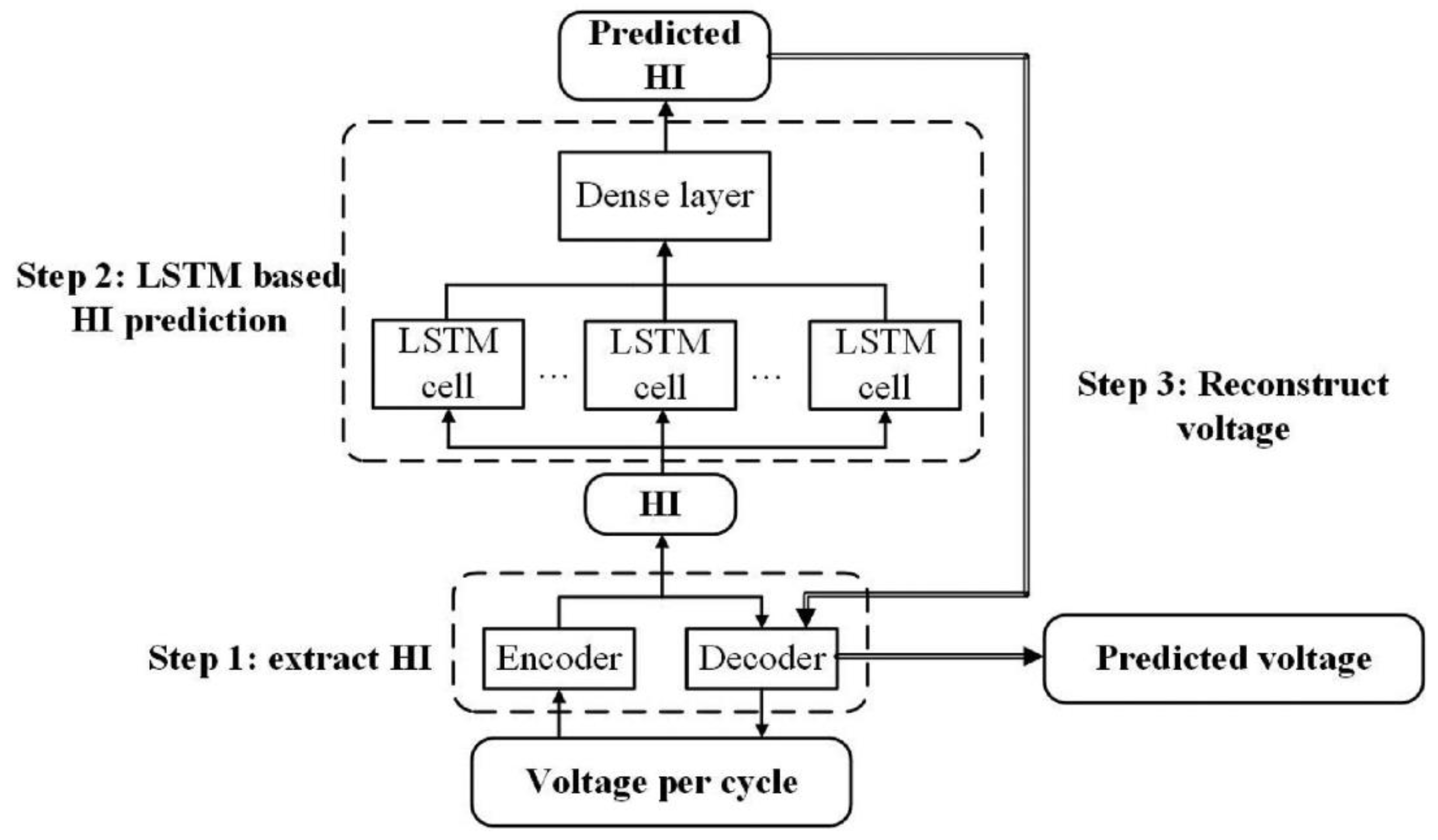
K. He et al. [68] suggested an auto-encoder (AE)-LSTM network model to forecast PEMFC degradation under vehicle running conditions, as shown in Figure 9. This approach uses a health indicator (HI) to characterize PEMFC degradation conditions before performing LSTM. Each dynamic load cycle extracts one HI value from the PEMFC output voltage using AE. Thus, HI may reflect the voltage change in the cycle level. The method proved effective for making performance predictions, with a maximum RMSE of 0.003513. This method can also analyze the degradation mechanism of PEMFCs. Therefore, this method can reliably predict PEMFC degradation progress and mechanisms, and help to undertake appropriate strategies to ensure PEMFC durability.
B. Zuo et al. [69] suggested a long-short-term memory neural network-based degradation prediction model for PEMFCs. The data were smoothed out by the Savitzky–Golay filter. Based on 25% data, the model can forecast fuel cell degradation with an R2 of 0.9065 for the test set. Yezerska et al. [70] employed an LSTM model, trained on experimental electrochemical data from a long-term H2 starvation/regeneration routine, to predict the effect of H2 starvation on PEMFC degradation. This study showed that a LSTM model is a reliable tool for predicting the stress behaviour of PEMFCs. Wang et al. [71] introduced a new prognostic model called navigation sequence-driven LSTM (NSD-LSTM) for the long-term prognosis of proton exchange membrane fuel cells (PEMFC). The approach involves generating a navigation sequence using an autoregressive integrated moving average model with exogenous variables. This sequence is then iteratively inputted into an LSTM during the implementation phase to achieve long-term predictions. Both the simulation and experimental results demonstrate that the proposed prognostic strategy exhibits better consistency in predicting the long-term degradation trend compared to other artificial neural network (ANN) models such as nonlinear autoregressive exogenous and echo state network models.
c.
Convolutional neural network
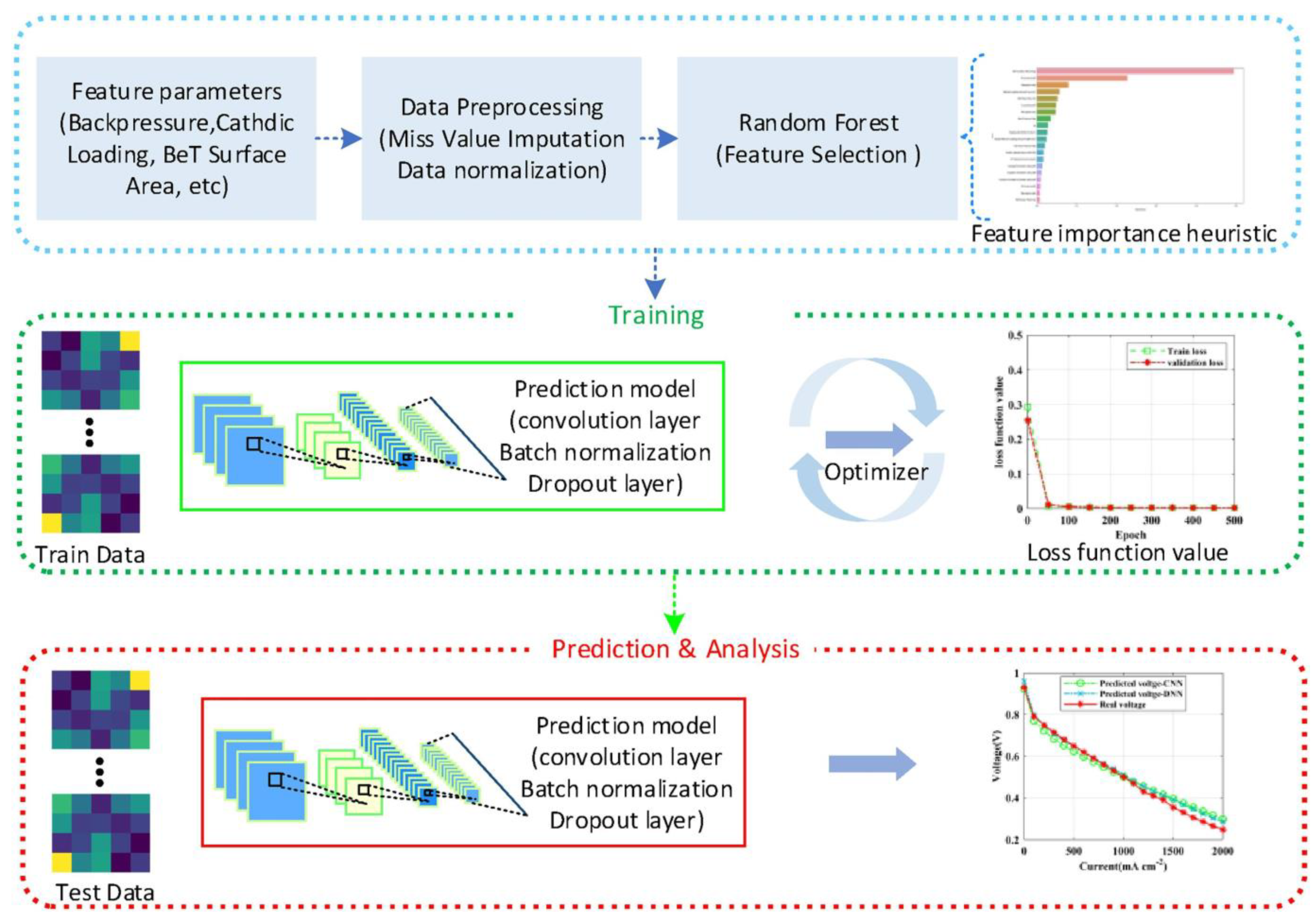
Convolutional neural networks (CNNs) feature weighted connections such as feed-forward neural networks. CNNs contain one or more convolutional layers that convolutionally process the input and send the output to the next layer. W. Huo et al. [72] employed deep learning methods to create a performance prediction model based on the random forest algorithm and convolutional neural networks, as shown in Figure 10. In the proposed method, the random forest technique was used to identify the essential input characteristics to enhance the quality of the training dataset. These characteristics were then utilized for training a convolutional neural network to predict the I–V polarization curve. The usefulness of the proposed model was assessed using actual I–V polarization curve data, and the findings revealed that the predicted curves had an excellent agreement with the actual curves. As a result, the suggested model may be a more cost-effective alternative to established approaches for estimating PEMFC performance.
Benaggoune et al. [73] proposed a multi-step-ahead prediction methodology for PEMFC degradation using dilated CNN architecture, as illustrated in Figure 11. An attention mechanism is also incorporated into the model to selectively focus on the most relevant features. The proposed method was compared with other ANN models, including the multilayer perceptron (MLP), LSTM, and bi-directional LSTM (Bi-LSTM) models. Comparisons with previous recurrent neural network approaches for forecasting PEMFC deterioration indicated that the suggested method performed better.
Wilberforce et al. [74] combined a bi-recurrent neural network (BiRNN) and a convolutional neural network (CNN) to predict the RUL of PEMFCs. The hybrid BiRNN-CNN model is shown in Figure 12. The BiRNN was used to capture the long-term dependencies in the data, while the CNN was used to extract features from the input data. The results showed that the BiRNN-CNN hybrid model outperformed other methods regarding prediction accuracy.
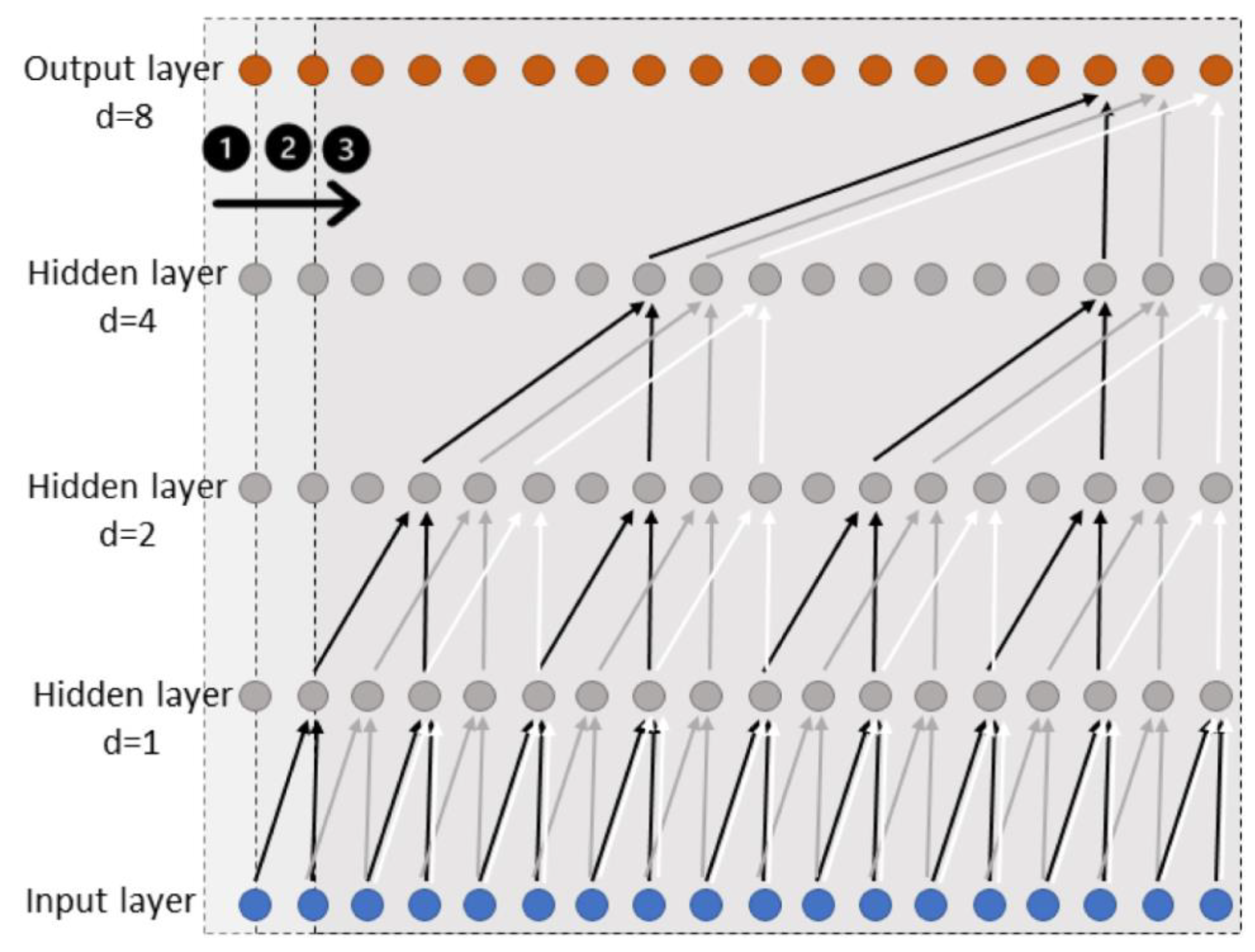
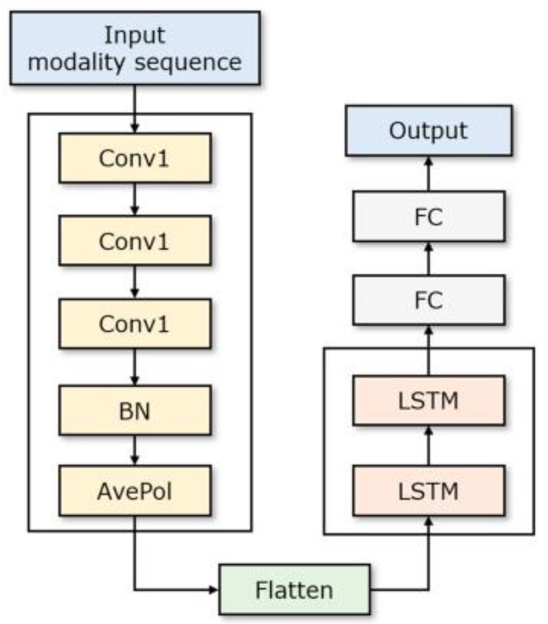
Recently, Sun et al. [75] presented a hybrid method combining the spatial feature extraction ability of a convolutional neural network (CNN) and the prediction ability of a long-short-term memory (LSTM) network to predict the degradation of a 110-kW commercial vehicle fuel cell system, as shown in Figure 13. The combination of CNN and LSTM can leverage the strengths of both methods in feature extraction and temporal modeling, respectively. The complete ensemble empirical mode decomposition (CEEMD) decomposes the raw stack voltage data to obtain modality sequences. Using CEEMD to decompose the raw stack voltage series could also help to extract more meaningful features for the model to learn. The hybrid CNN-LSTM model showed a significant increase in prediction accuracy compared to either LSTM or CNN alone.
d.
Echo state network
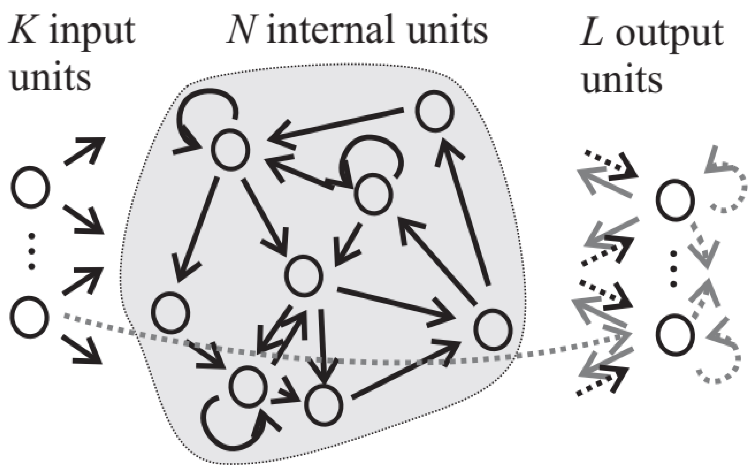
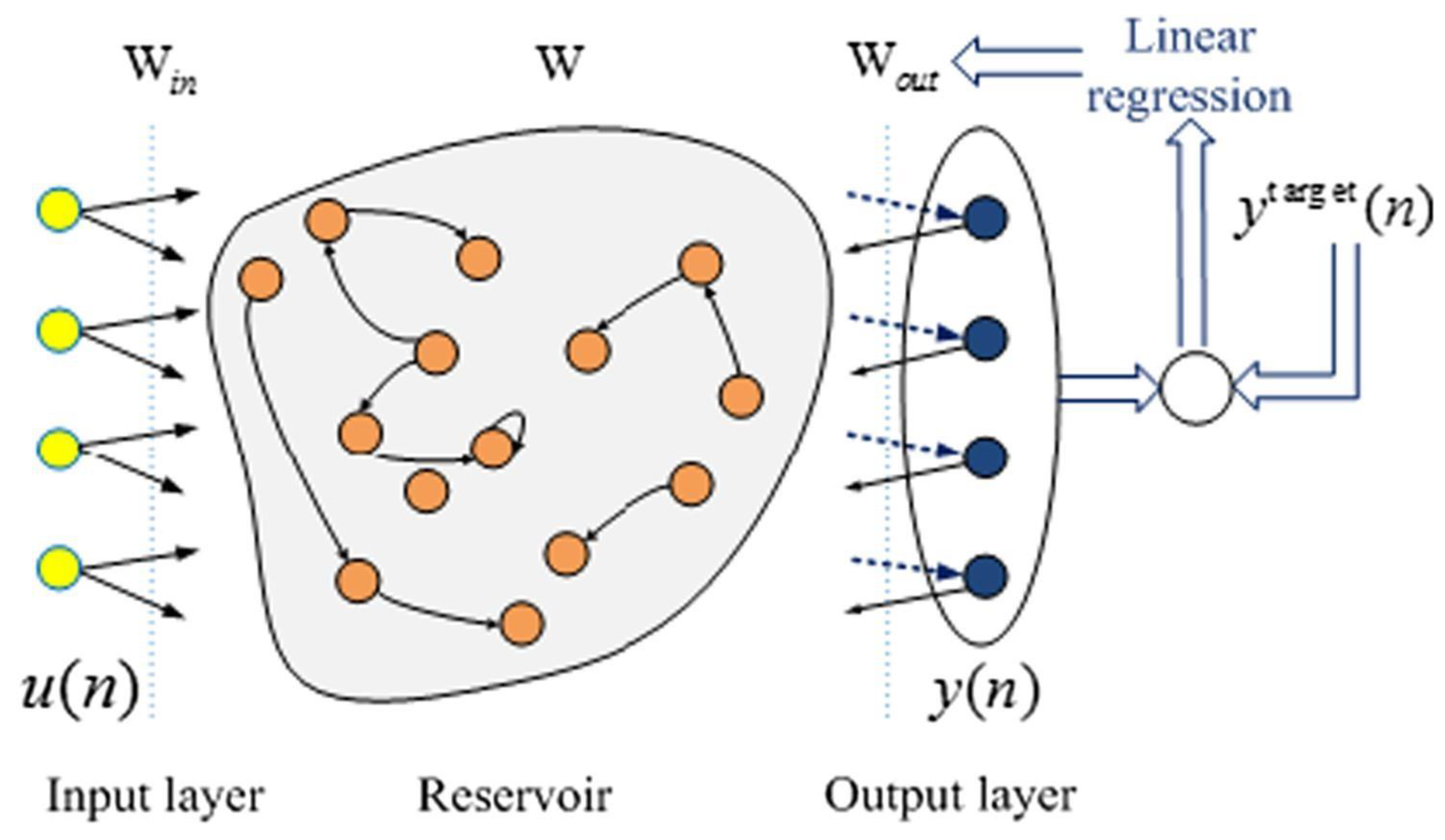
Echo state network (ESN) is a new approach for RNN that Jaeger introduced in 2001. This architecture proposes a better human brain paradigm than traditional ANN [76]. An ESN comprises an input layer, a dynamic reservoir with random connections, and an output layer, as shown in Figure 14. The randomly connected reservoir is also considered to be a key feature of ESN, as it can produce highly complex and nonlinear dynamics that are difficult to achieve with traditional RNNs. Compared to other ANN models, ESN training is faster and more accurate [77].
Morando et al. [78] utilized the ESN architecture to perform a long-term prognostics analysis and estimate the voltage drop during the PEMFC degradation process. The study demonstrated that the ESN-based approach achieved an accurate prediction with an error of less than 5%, indicating its potential for PEMFC prognostics. The authors also noted that the ESN architecture has low computational requirements, making it a promising tool for practical applications. Zhang et al. [79] proposed a new ESN architecture for predicting PEMFC degradation called a multi-reservoir echo state network with a mini reservoir (MRM). In the MRM architecture, the mini reservoirs organize the state of the main reservoirs. The particle swarm optimization (PSO) algorithm was used to identify the best structure of the main reservoirs and neurons. The Savitzky–Golay filter was utilized to remove noise from the raw data. The prediction accuracy was inversely related to the training set length under static conditions, and the predictability was at its highest under dynamic conditions at 550 h. Yue et al. [53] used a multi-step echo state network to predict the system failure and improve the durability of PEMFCs operating under dynamic load. Recently, Hua et al. [80] proposed a novel approach called MIMO-ESN, which stands for echo state network with multiple inputs and multiple outputs, to predict the RUF of PEMFCs. The MIMO-ESN incorporates operating parameters such as the stack current, stack temperature, and reactant pressures as inputs to the model, as shown in Figure 15. These parameters significantly impact the stack voltage, making them valuable inputs for the model. The authors demonstrated that MIMO-ESN outperformed the single-input ESN model in terms of prediction accuracy. Moreover, MIMO-ESN performed better than SISO-ESN.
e.
Summary of ANN models
ANN models offer several advantages, such as fast computation speed and high prediction accuracy, without the need for extensive physical knowledge. They excel at establishing input–output relationships based on large datasets, enabling real-time performance prediction for PEM fuel cells. Although training an ANN model may require a comparable amount of time to setting up a physical model, the computational speed of an ANN model is significantly faster once trained. Additionally, models capable of predicting multiple output variables, including voltage, temperature, and outlet conditions, are beneficial for fuel cell stack and system control. However, developing data-driven models necessitates a substantial amount of experimental data, and the impact of the data quality on the performance of data-driven models is an area of significant research interest.

2.2.2. Support Vector Machine Model

Similar to ANNs, the support vector machine (SVM) model is adopted as a modeling method for the nonlinear empirical models. SVMs provide good generalization performance because they are more tolerable to noisy and erroneous data [81]. When SVMs are used for solving regression problems, it is referred to as support vector regression (SVR).
Legala et al. [82] conducted a comparative study of the performance of ANNs and SVR for predicting cell voltage, membrane resistance, and membrane water content. According to the research, The ANN outperformed SVR, particularly on multivariate output regression. However, SVR proved advantageous in modeling simple regressions, reducing the computational cost without compromising accuracy. Wu et al. [83] introduced a modified relevance vector machine (RVM) as a Bayesian alternative to SVM for predicting the aging of PEMFC stacks. The authors compared the results of the proposed modified RVM method to those of SVM. They found that the modified RVM performed better, particularly in cases where there were relatively small training data sets. Wu et al. [84] further demonstrated an advanced model for predicting PEMFC degradation using a self-adaptive relevance vector machine (RVM). The results showed that it presents a better predictive performance than classic SVM, with prediction errors reported to be 30–40% lower. Additionally, the modified RVM model performed better than the original RVM model. Chen et al. [85] introduced a new method for predicting PEMFC degradation using multi-kernel relevance vector regression (MRVR) and the whale optimization algorithm (WOA). The PEMFC degradation prediction model is built using MRVR, while the WOA improves prediction accuracy by automatically optimizing the weight and kernel parameters. This approach creates a solid model that covers various operations by combining laboratory data with real-world driving situations. The results showed that PEMFC degradation is predicted more accurately using a multi-kernel function than a single-kernel function under different operational conditions.

2.2.3. Fuzzy Logic Model

Fuzzy logic (FL) is a classification method that imitates human reasoning and deals with fuzzy systems. It can function as a pattern recognition or residual generator, similar to NN [86]. FL is used when processes are nonlinear, subjective, or too complex for precise mathematical modeling. The FL model clusters data points and assigns them to similar clusters based on their membership function, which can be trapezoidal, linear, or curved depending on the fuzzy if-then rules [7,86].
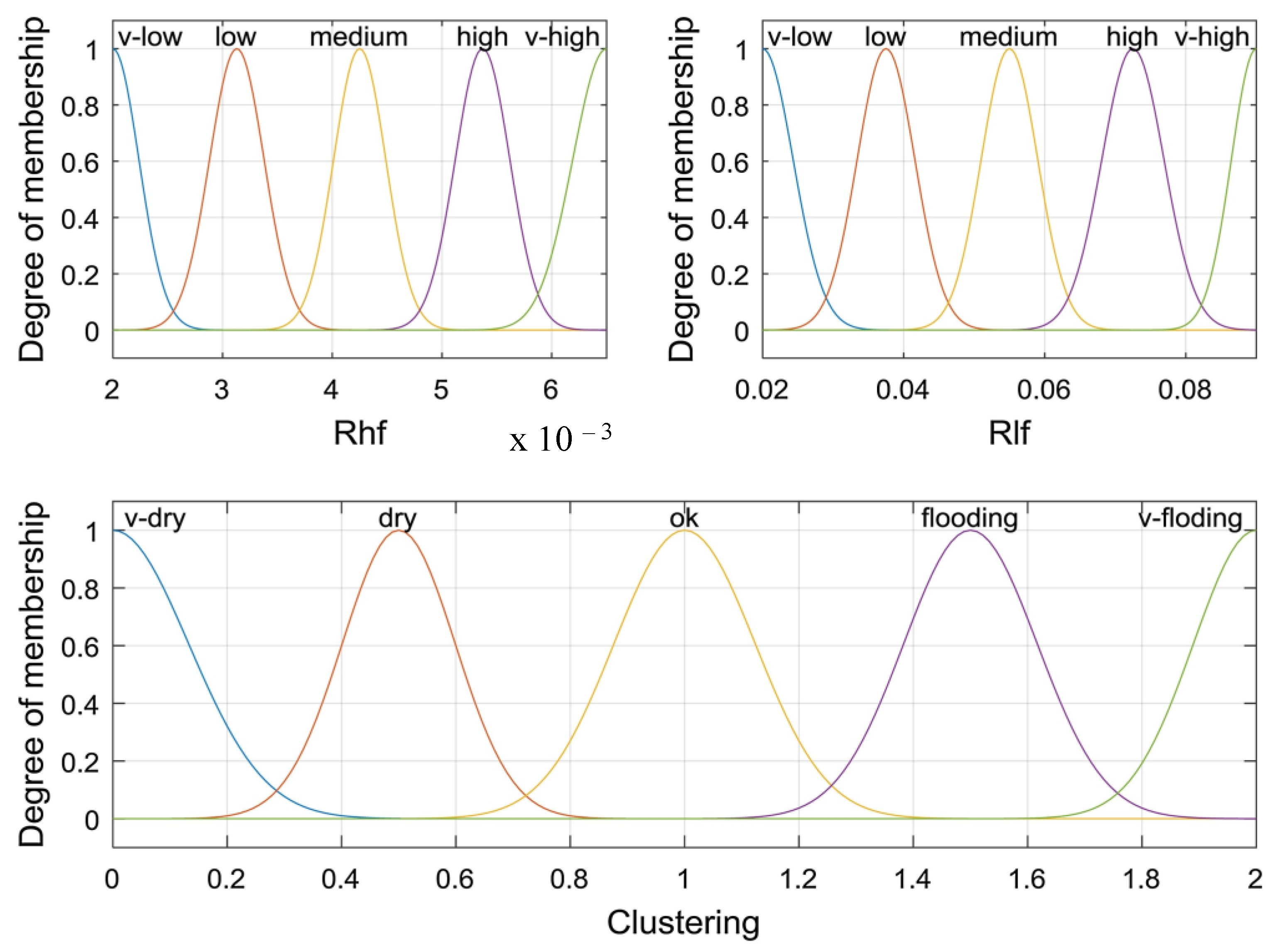
Rubio et al. [86] developed a fuzzy logic model to determine the real-time degree of flooding or dehydration in a PEMFC. The model uses changes in the voltage slope and voltage oscillations as characteristics to estimate the water content, which are defined as fuzzy variables. The fuzzy sets have gradual transitions between them, defined by trapezoidal functions, with membership functions having the same profile and number of values but different numerical values for the parameters. The model’s accuracy was validated using electrochemical impedance spectroscopy, and the results showed that PEM fuel cell faults at different levels could be accurately diagnosed using this approach. Mammar et al. [87] illustrated a fuzzy logic model to diagnose the hydration state of PEMFCs. Fuzzy logic inference and clustering were used to determine the health status of the membrane. The block diagram of the fuzzy logic clustering and membership function is shown in Figure 16. The proposed model and fuzzy logic clustering were tested with a step change of humid airflow and current. The results demonstrated that the fuzzy logic clustering could diagnose cases of flooding and drying in the membrane through the impedance behavior in the Nyquist plot.
Combining ANNs with fuzzy logic can create an efficient approach for various modeling systems. A neuro-fuzzy system is a fuzzy system that learns its parameters, including the proper membership functions and fuzzy rules, from artificial neural networks. The adaptive neuro-fuzzy inference system (ANFIS) is one of the most popular forms of neuro-fuzzy systems [88]. It has five layers: input membership function layer, rule layer, normalization layer, output membership function layer, and output layer. Figure 17 shows the ANFIS structure with two inputs and one output. The nodes with squares are adaptive nodes that can change their values, while the nodes with circles are fixed with constant values.
ANFISs have been used in many studies to predict the performance and degradation of PEMFCs. S. Rezazadeh et al. [88] utilized ANFISs to simulate the performance of PEMFCs. According to the research, the ANFIS model was practical and effective for the life prediction of PEMFCs. Wilberforce et al. [89] used ANFIS to evaluate the PEMFC performance under different ambient conditions. The experimental data obtained in the laboratory were used to train the model with input and output parameters, which were then evaluated using an independent variable. The predicted results indicated that ANFIS could accurately forecast fuel cell performance behavior. Silva et al. [90] suggested a new approach using ANFIS to predict PEMFC degradation. The proposed method considers the output voltage as the indicator for PEMFC degradation, as it is a low-cost and non-intrusive measure that is easy to implement. The results of the validation experiments demonstrate that this methodology is effective for predicting PEMFC degradation. Liu et al. [91] compared the accuracy and computational efficiency of the adaptive neuro-fuzzy inference system (ANFIS) with various fuzzy inference system creation strategies to other methods. The ANFIS with fuzzy c-means showed the most accurate performance among these methods.

2.2.4. Gaussian Process

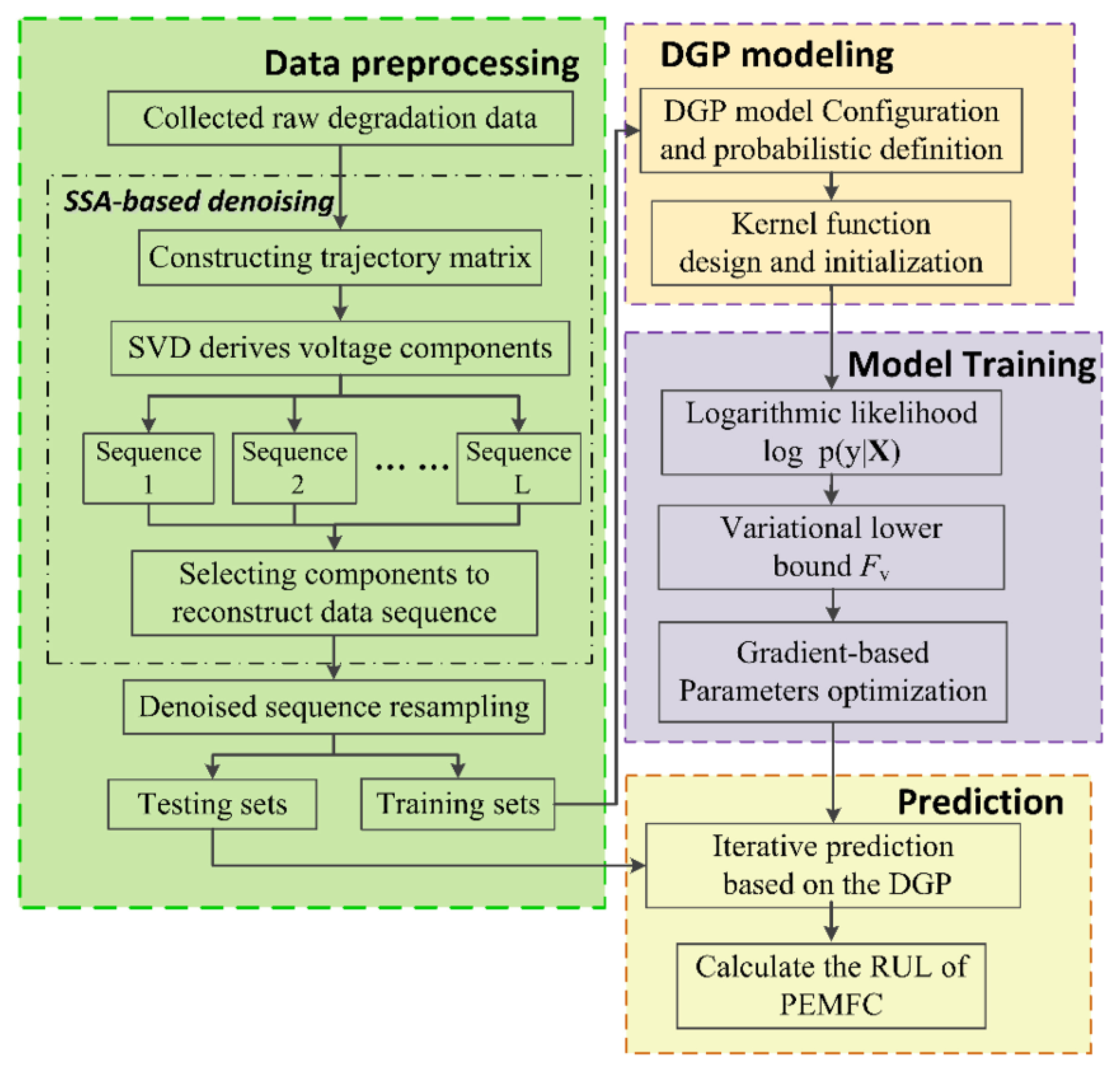
The Gaussian process (GP) uses probability theory and mathematical statistics to depict the RUL distribution’s unpredictability and uncertainty [48]. Sun et al. [92] modelled the distribution of the voltages at different current points as a Gaussian process that adaptively incorporates data that refine the characterization in a flexible manner. Zhu et al. [93] proposed a Gaussian process state space (GPSS) model that can effectively deal with model uncertainty and disturbances to predict the degradation tendency and uncertainty of PEMFCs. The GPSS model estimates the uncertainty distribution, which a confidence interval of 95% can represent. The accuracy of the predicted results is within ±10% of the actual RUL. However, using only voltage as a health indicator might not reflect the complete changes in the PEMFC. To address this issue, Tang et al. [94] used stack voltage and power to construct a health indicator which was integrated into the adaptive Gaussian process regression (AGPR) method to describe the PEMFC degradation process. The AGPR method was compared with the ANN method. The results showed that AGPR outperformed the ANN method in prediction and probability distribution. Xie et al. [95] proposed a degradation prediction method for PEMFC RUL using a combination of the deep Gaussian process (DGP) and singular spectrum analysis (SSA) methods. The degradation prediction framework based on SSA-DGP is illustrated in Figure 18. The measurement data are preprocessed using SSA to remove noise and spikes. DGP, a deep structural model consisting of many Gaussian process latent variable models, represents the nonlinear details of degradation data. Experimental data of the PEMFCs evaluate the effectiveness of the proposed method under steady-state conditions.
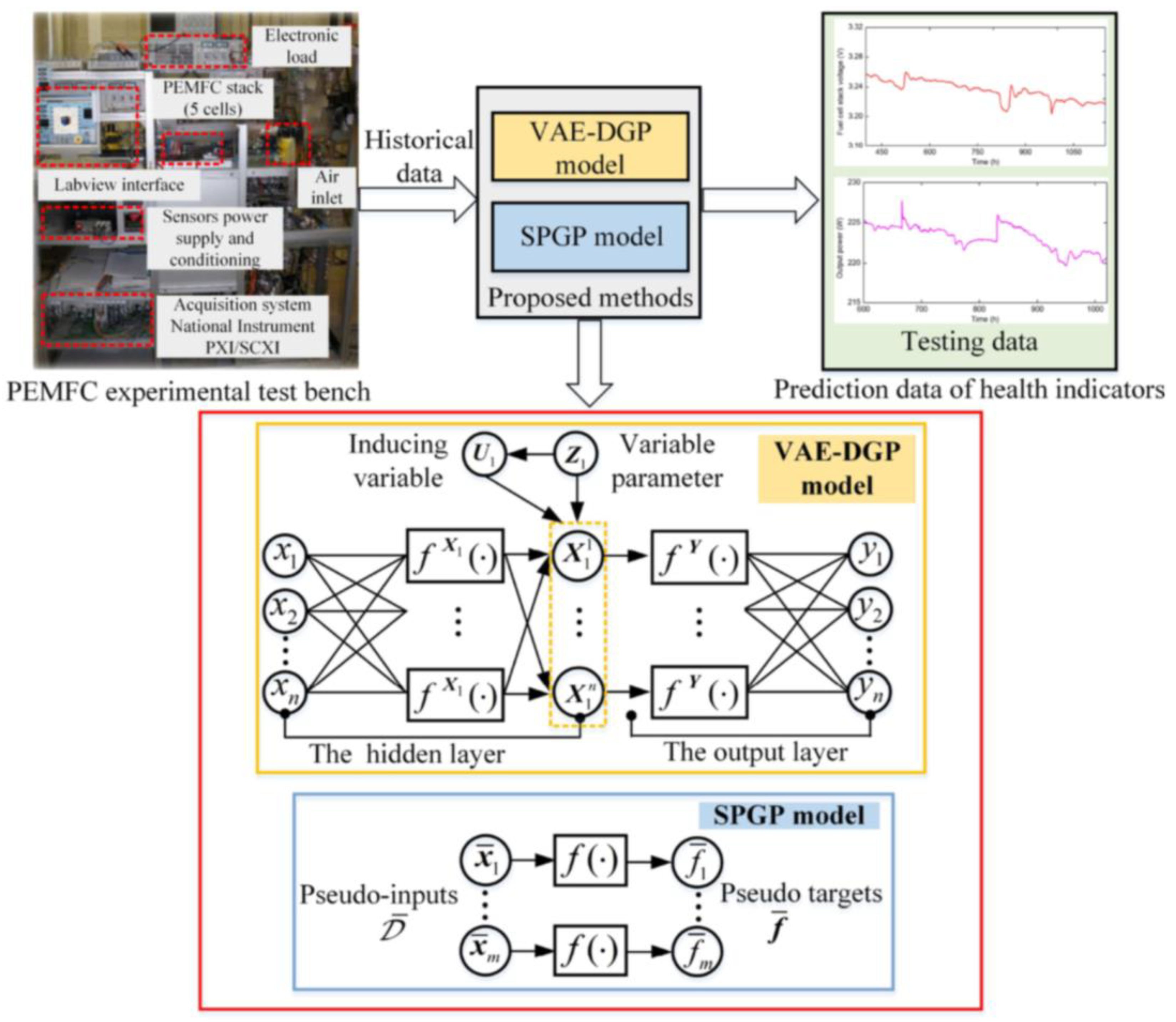
Using sparse the pseudo-input Gaussian process (SPGP) and variational auto-encoded deep Gaussian process (VAE-DGP) methods, Deng et al. [96] introduced two unique Gaussian process regression modeling frameworks to forecast the aging trend of PEMFCs, as shown in Figure 19. Static and dynamic aging experiments were conducted over long durations to validate the prediction performance thoroughly. The SPGP and VAE-DGP methods build single-input and multi-input structures to evaluate their results versus current models such as BPNN and LSTM. The results demonstrate the superiority of the proposed methods over other data-driven approaches. The SPGP is also better-suited for large data regimes, while the VAE-DGP functions better for small data regimes.

2.2.5. Summary

The data-driven approach involves using available data to create a model that can make predictions or decisions without explicitly understanding the underlying system dynamics. It has some advantages and disadvantages, as follow.
Advantages of the data-driven approach:
  • Data-driven models can make accurate predictions or decisions without requiring a deep understanding of the underlying system. This can be advantageous when dealing with complex systems or when the system dynamics are not well understood.
  • Data-driven models can capture complex relationships and interactions between variables, even when the underlying mechanisms are not well understood.
  • Data-driven models can be more flexible and adaptable to changing conditions or new data.
  • Disadvantages of the data-driven approach:
  • Data-driven models often lack interpretability, meaning it can be challenging to understand and explain the reasons behind their predictions or decisions.
  • Data-driven models may struggle with extrapolating beyond the range of the available data. They might not accurately predict outcomes in scenarios that differ significantly from the training data.
  • The accuracy and reliability of data-driven models heavily depend on the quality, completeness, and representativeness of the input data.
  • Data-driven models require access to sufficient and relevant data, which may not always be readily available.

2.3. Hybrid Approach

Researchers have developed several hybrid approaches that incorporate model-based and data-driven methods utilizing different hybrid strategies. Hybrid approaches provide a greater prognosis accuracy than single methods, but their more complicated structure increases their computing complexity. They are promising for real-world applications which require a high prognostic accuracy and the balancing of computing resources and precision. The hybrid prognostics methods can be classified into three types based on different hybrid strategies [6]:
(1)
The model-based approach extracts degradation indexes, then the data-driven approach predicts the degradation trend and estimates the RUL.
(2)
Data-driven methods fit the degradation model or measurement data to predict the future degradation trend, then model-based methods estimate the RUL.
(3)
Model-based and data-driven methods are applied together. The final degradation results are obtained by weighing each result.

2.3.1. Hybrid Strategy 1

Zhou et al. [97] proposed a hybrid method to predict PEMFC degradation. The non-stationary trend in the original data was eliminated using a physical aging model, and the linear component was filtered using an autoregressive and moving average model. Time delay neural networks were trained using the remaining nonlinear pattern to make the final prediction. Yue et al. [53] introduced an online approach for identifying and predicting the degradation of PEM fuel cells, using an independent-of-operating-conditions nonlinear regression procedure to derive a degradation indicator. A multi-step window-sliding echo state network (ESN) model was then used to estimate the future trend of identified degradation indicators. The results showed that degradation detection could be done in real time without further measurements. Furthermore, compared to other prognostic methods, such as stacked LSTM and PF, the proposed prognostic strategy achieved higher accuracy and required less computation time. Wang et al. [98] presented a fusion prognostics approach for fuel cells that are operating in dynamic scenarios. Their strategy involved identifying the system dynamics using an electrochemical mechanism model and extracting degradation indicators based on the identified model parameters. They then created a reduced-dimensional symbolic representation using a long-short-term memory network to forecast the degradation progression. The findings indicate that the degradation mechanism model can successfully identify degradation indicators even in dynamic operating conditions. By utilizing the prognostics model, precise remaining useful life (RUL) predictions can be made based on the extracted degradation indicators.

2.3.2. Hybrid Strategy 2

Cheng et al. [99] proposed a hybrid approach to improve the accuracy of the prognostics results when characterization is uncertain. Using a least square support vector machine (LSSVM) for preliminary prognostics, followed by a regularized particle filter (RPF) to obtain the final RUL probability distribution of PEMFC, the method combines the benefits of both data-driven and model-based approaches. The LSSVM predictions are used as new observation values in the RPF prognostic framework. The results confirmed that PEMFC RUL predictions could be an improvement from the hybrid method. However, the method has not been tested under variable loading conditions, and the authors intend to improve the framework to address this limitation. Liu et al. [100] first predicted the long-term deterioration trend using the evolutionary algorithm and adaptive neuro-fuzzy inference system. Using degradation data from the first phase, a semi-empirical degradation model based on the adaptive unscented Kalman filter algorithm estimates the remaining useful life. Compared to existing models, this hybrid method produced more accurate prognostic results.

2.3.3. Hybrid Strategy 3

Pan et al. [60] and Zhou et al. [101] proposed hybrid strategies with simultaneous model-based and data-driven methods. An empirical or semi-empirical aging model captures the overall degradation trend. Meanwhile, a neural network predicted the observed measurement data’s local nonlinear degradation characteristic. The results from various methods are fused using the weighted average methodology to obtain the final prediction results. Predicting fuel cell degradation using an adaptive Kalman filter and NARX neural network was suggested by Pan et al. [60]. An empirical voltage degradation mode and NAR neural network incorporated with the moving window technique was proposed in [101]. The above-proposed hybrid approaches showed a higher accuracy for the degradation and RUL prediction of PEMFCs than conventional prediction single methods.

2.3.4. Summary

The hybrid approach combines elements of both model-based and data-driven approaches to leverage their respective strengths. It has some advantages and disadvantages as follows.
Advantages of hybrid approach:
  • By combining the strengths of both model-based and data-driven approaches, hybrid models can potentially offer higher accuracy and reliability in predictions and decisions.
  • Hybrid models can effectively model and capture complex and nonlinear relationships between variables. The model-based component can provide an overall degradation trend, while the data-driven component can handle the fine-grained details and nonlinearity present in the data.
  • Hybrid models can adapt to different levels of data availability. In cases where data are limited, the model-based component can provide useful insights and predictions. When more data become available, the data-driven component can be integrated to refine and update the model.
  • Hybrid models can better generalize new or unseen data compared to data-driven models. The model-based component can improve the model’s ability to make accurate predictions in conditions beyond the training data.
  • Disadvantage of hybrid approach:
  • Hybrid models can be more complex to develop and implement compared to using a single modeling approach.
  • Hybrid models may require more computational resources, especially if the model-based component involves complex mathematical equations or simulations.
  • Validating and verifying hybrid models can be more demanding than with single modeling approaches. Ensuring the accuracy and reliability of both components and their integration requires careful testing and comparison with experimental data.

3. Challenges and Prospects

Degradation models are critical in understanding the performance behavior of fuel cell systems during long-term operation. Various operational factors, such as temperature, pressure, relative humidity, flow rate, and cooling conditions, impact the fuel cell’s performance. It is challenging to accurately predict this system’s states with a high degree of freedom. Physics-based models can simulate the physical and electrochemical processes within the fuel cell components, but they are computationally expensive and contain many parameters that can differ across studies. Data-driven models offer fast and accurate predictions based on historical data, but they may not generalize well to new operating conditions or scenarios. Hybrid prediction approaches offer higher accuracy but increase the complexity of the calculations. Due to the fast changes during operation, the PEMFCs in electric cars run under complicated problems. Complex dynamic conditions must be considered to prove the accuracy of the degradation models. Currently, voltage and power are considered to be the primary aging indicators, but they cannot accurately forecast the lifespan of PEMFCs in electric vehicles with dynamic operating conditions. It is essential to discover aging indicators that may be used to reliably forecast PEMFC life in real-time with little computing overhead under dynamic conditions. Despite these challenges, the prospect of developing reliable degradation models is promising. It can help to optimize the design and operation of fuel cell systems and inform maintenance and replacement strategies. Accurate degradation models can also aid in identifying the root causes of degradation and facilitate the development of new materials and technologies that improve system durability and reliability.

4. Conclusions and Perspectives

Evaluating fuel cells and system performance is essential for the development of high-performance, long-lasting, and cost-effective fuel cells. This paper thoroughly reviewed the various performance degradation models for PEMFCs. First, the introduction, working principles, and mechanical, chemical, and thermal degradations of the PEMFC system are briefly presented. As well, end-of-life criteria are defined. Secondly, PEMFC degradation modeling approaches are presented, including the model-based, data-driven, and hybrid approaches. Finally, future research challenges and directions are presented to guide future life prediction technique research.
Even though durability studies in the literature show significant advances, several facets of the PEMFC degradation prediction system still need improvement.
  • Current studies show that voltage and power are the most reliable indicators of PEMFC age; however, these metrics are indistinct when applied to dynamic conditions. Indeed, the monotonic drop in voltage or power is less visible in dynamic operating situations due to load current uncertainty. Therefore, extracting aging indicators that may be used to make reliable online estimates of PEMFC lifetime with little computational effort is crucial.
  • The prediction of the degradation and lifetime of fuel cells plays a significant role in the operation and maintenance of fuel cell vehicles. Thus, there is an immediate need to propose a method for online lifetime prediction under the dynamic responses of the real-world. The main idea is to build mathematical models or “black box” models to quickly forecast the intermediate or long period using real-time collected data of actual running fuel cell vehicles. Despite this progress, online prediction remains a significant obstacle due to the complicated structure of machine learning algorithms, which makes online process implementation difficult. In addition, PEMFCs in electric vehicles operate under complicated conditions due to the rapid changing of electric vehicle operation. Therefore, adaptive prediction methods are necessary for enhanced online prediction accuracy.

Author Contributions

H.-L.N.: Conceptualization, Methodology, Formal analysis, Visualization, Writing—original draft. S.-M.L.: Resources. S.Y.: Methodology, Supervision, Funding acquisition, Project administration. All authors have read and agreed to the published version of the manuscript.

Funding

This work was supported by the Technology Innovation Program (20004963) funded By the Ministry of Trade, Industry & Energy (MOTIE, Korea) and by the Technology Innovation Program (20015756) funded by the Ministry of Trade, Industry & Energy (MOTIE, Korea).

Data Availability Statement

No new data were created or analyzed in this study. Data sharing is not applicable to this article.

Conflicts of Interest

The authors declare no conflict of interest.

References

  1. Jiao, K.; Xuan, J.; Du, Q.; Bao, Z.; Xie, B.; Wang, B.; Zhao, Y.; Fan, L.; Wang, H.; Hou, Z.; et al. Designing the next Generation of Proton-Exchange Membrane Fuel Cells. Nature 2021, 595, 361–369. [Google Scholar] [CrossRef] [PubMed]
  2. Itaoka, K.; Saito, A.; Sasaki, K. Public Perception on Hydrogen Infrastructure in Japan: Influence of Rollout of Commercial Fuel Cell Vehicles. Int. J. Hydrogen Energy 2017, 42, 7290–7296. [Google Scholar] [CrossRef]
  3. Borup, R.L.; Kusoglu, A.; Neyerlin, K.C.; Mukundan, R.; Ahluwalia, R.K.; Cullen, D.A.; More, K.L.; Weber, A.Z.; Myers, D.J. Recent Developments in Catalyst-Related PEM Fuel Cell Durability. Curr. Opin. Electrochem. 2020, 21, 192–200. [Google Scholar] [CrossRef]
  4. Nguyen, H.L.; Han, J.; Vu, H.N.; Yu, S. Investigation of Multiple Degradation Mechanisms of a Proton Exchange Membrane Fuel Cell under Dynamic Operation. Energies 2022, 15, 9574. [Google Scholar] [CrossRef]
  5. Wu, H.W. A Review of Recent Development: Transport and Performance Modeling of PEM Fuel Cells. Appl. Energy 2016, 165, 81–106. [Google Scholar] [CrossRef]
  6. Liu, H.; Chen, J.; Hissel, D.; Lu, J.; Hou, M.; Shao, Z. Prognostics Methods and Degradation Indexes of Proton Exchange Membrane Fuel Cells: A Review. Renew. Sustain. Energy Rev. 2020, 123, 109721. [Google Scholar] [CrossRef]
  7. Zhao, J.; Li, X.; Shum, C.; McPhee, J. A Review of Physics-Based and Data-Driven Models for Real-Time Control of Polymer Electrolyte Membrane Fuel Cells. Energy AI 2021, 6, 100114. [Google Scholar] [CrossRef]
  8. Zheng, Z.; Petrone, R.; Péra, M.C.; Hissel, D.; Becherif, M.; Pianese, C.; Yousfi Steiner, N.; Sorrentino, M. A Review on Non-Model Based Diagnosis Methodologies for PEM Fuel Cell Stacks and Systems. Int. J. Hydrogen Energy 2013, 38, 8914–8926. [Google Scholar] [CrossRef]
  9. Hua, Z.; Zheng, Z.; Pahon, E.; Péra, M.C.; Gao, F. A Review on Lifetime Prediction of Proton Exchange Membrane Fuel Cells System. J. Power Sources 2022, 529, 231256. [Google Scholar] [CrossRef]
  10. Vichard, L.; Steiner, N.Y.; Zerhouni, N.; Hissel, D. Hybrid Fuel Cell System Degradation Modeling Methods: A Comprehensive Review. J. Power Sources 2021, 506, 230071. [Google Scholar] [CrossRef]
  11. Pan, Y.; Wang, H.; Brandon, N.P. Gas Diffusion Layer Degradation in Proton Exchange Membrane Fuel Cells: Mechanisms, Characterization Techniques and Modelling Approaches. J. Power Sources 2021, 513, 230560. [Google Scholar] [CrossRef]
  12. Pan, M.; Pan, C.; Li, C.; Zhao, J. A Review of Membranes in Proton Exchange Membrane Fuel Cells: Transport Phenomena, Performance and Durability. Renew. Sustain. Energy Rev. 2021, 141, 110771. [Google Scholar] [CrossRef]
  13. Okonkwo, P.C.; Ben Belgacem, I.; Emori, W.; Uzoma, P.C. Nafion Degradation Mechanisms in Proton Exchange Membrane Fuel Cell (PEMFC) System: A Review. Int. J. Hydrogen Energy 2021, 46, 27956–27973. [Google Scholar] [CrossRef]
  14. Tzelepis, S.; Kavadias, K.A.; Marnellos, G.E.; Xydis, G. A Review Study on Proton Exchange Membrane Fuel Cell Electrochemical Performance Focusing on Anode and Cathode Catalyst Layer Modelling at Macroscopic Level. Renew. Sustain. Energy Rev. 2021, 151, 111543. [Google Scholar] [CrossRef]
  15. Dafalla, A.M.; Wei, L.; Habte, B.T.; Guo, J.; Jiang, F. Membrane Electrode Assembly Degradation Modeling of Proton Exchange Membrane Fuel Cells: A Review. Energies 2022, 15, 9247. [Google Scholar] [CrossRef]
  16. Raeesi, M.; Changizian, S.; Ahmadi, P.; Khoshnevisan, A. Performance Analysis of a Degraded PEM Fuel Cell Stack for Hydrogen Passenger Vehicles Based on Machine Learning Algorithms in Real Driving Conditions. Energy Convers. Manag. 2021, 248, 114793. [Google Scholar] [CrossRef]
  17. Nguyen, H.L.; Han, J.; Nguyen, X.L.; Yu, S.; Goo, Y.M.; Le, D.D. Review of the Durability of Polymer Electrolyte Membrane Fuel Cell in Long-Term Operation: Main Influencing Parameters and Testing Protocols. Energies 2021, 14, 4048. [Google Scholar] [CrossRef]
  18. Hissel, D.; Pera, M.C. Diagnostic & Health Management of Fuel Cell Systems: Issues and Solutions. Annu. Rev. Control 2016, 42, 201–211. [Google Scholar]
  19. Yu, S.; Jung, D. Thermal Management Strategy for a Proton Exchange Membrane Fuel Cell System with a Large Active Cell Area. Renew. Energy 2008, 33, 2540–2548. [Google Scholar] [CrossRef]
  20. Büchi, F.N.; Inaba, M.; Schmidt, T.J. Polymer Electrolyte Fuel Cell Durability; Springer: New York, NY, USA, 2009; ISBN 9780128114599. [Google Scholar]
  21. Jouin, M.; Bressel, M.; Morando, S.; Gouriveau, R.; Hissel, D.; Péra, M.C.; Zerhouni, N.; Jemei, S.; Hilairet, M.; Ould Bouamama, B. Estimating the End-of-Life of PEM Fuel Cells: Guidelines and Metrics. Appl. Energy 2016, 177, 87–97. [Google Scholar] [CrossRef] [Green Version]
  22. Mayur, M.; Gerard, M.; Schott, P.; Bessler, W.G. Lifetime Prediction of a Polymer Electrolyte Membrane Fuel Cell under Automotive Load Cycling Using a Physically-Based Catalyst Degradation Model. Energies 2018, 11, 2054. [Google Scholar] [CrossRef] [Green Version]
  23. Futter, G.A.; Latz, A.; Jahnke, T. Physical Modeling of Chemical Membrane Degradation in Polymer Electrolyte Membrane Fuel Cells: Influence of Pressure, Relative Humidity and Cell Voltage. J. Power Sources 2019, 410–411, 78–90. [Google Scholar] [CrossRef]
  24. Ferreira, R.B.; Falcão, D.S.; Pinto, A.M.F.R. Simulation of Membrane Chemical Degradation in a Proton Exchange Membrane Fuel Cell by Computational Fluid Dynamics. Int. J. Hydrogen Energy 2021, 46, 1106–1120. [Google Scholar] [CrossRef]
  25. Singh, R.; Sui, P.C.; Wong, K.H.; Kjeang, E.; Knights, S.; Djilali, N. Modeling the Effect of Chemical Membrane Degradation on PEMFC Performance. J. Electrochem. Soc. 2018, 165, F3328–F3336. [Google Scholar] [CrossRef] [Green Version]
  26. Hasan, M.; Chen, J.; Waldecker, J.R.; Santare, M.H. Predicting Fatigue Lifetimes of a Reinforced Membrane in Polymer Electrolyte Membrane Fuel Cell Using Plastic Energy. J. Power Sources 2022, 539, 231597. [Google Scholar] [CrossRef]
  27. Zhou, X.; Qiu, D.; Peng, L.; Lai, X. Numerical and Experimental Characterization of Gas Permeation through Membranes with Consideration of Mechanical Degradation in Proton Exchange Membrane Fuel Cells. J. Power Sources 2023, 556, 232489. [Google Scholar] [CrossRef]
  28. Zhang, X.; Pisu, P. Prognostic-Oriented Fuel Cell Catalyst Aging Modeling and Its Application to Health-Monitoring and Prognostics of a PEM Fuel Cell. Int. J. Progn. Health Manag. 2014, 5, 1–16. [Google Scholar] [CrossRef]
  29. Darling, R.M.; Meyers, J.P. Kinetic Model of Platinum Dissolution in PEMFCs. J. Electrochem. Soc. 2003, 150, A1523. [Google Scholar] [CrossRef]
  30. Li, Y.; Moriyama, K.; Gu, W.; Arisetty, S.; Wang, C.Y. A One-Dimensional Pt Degradation Model for Polymer Electrolyte Fuel Cells. J. Electrochem. Soc. 2015, 162, F834–F842. [Google Scholar] [CrossRef] [Green Version]
  31. Holby, E.F.; Morgan, D. Application of Pt Nanoparticle Dissolution and Oxidation Modeling to Understanding Degradation in PEM Fuel Cells. J. Electrochem. Soc. 2012, 159, B578–B591. [Google Scholar] [CrossRef]
  32. Polverino, P.; Pianese, C. Model-Based Prognostic Algorithm for Online RUL Estimation of PEMFCs. In Proceedings of the 2016 3rd Conference on Control and Fault-Tolerant Systems (SysTol), Barcelona, Spain, 7–9 September 2016; IEEE Computer Society: Washington, DC, USA, 2016; pp. 599–604. [Google Scholar]
  33. Koltsiva, E.M.; Vasilenko, V.A.; Shcherbakov, A.I.; Fokina, E.A.; Bogdanovskaya, V.A. Mathematical Simulation of PEMFC Platinum Cathode Degradation Accounting Catalyst’s Nanoparticles Growth. Chem. Eng. Trans. 2018, 70, 1303–1308. [Google Scholar] [CrossRef]
  34. Jahnke, T.; Baricci, A.; Rabissi, C.; Casalegno, A. Erratum: Physical Modeling of Catalyst Degradation in Low Temperature Fuel Cells: Platinum Oxidation, Dissolution, Particle Growth and Platinum Band Formation [J. Electrochem. Soc., 167, 013523 (2020)]. J. Electrochem. Soc. 2020, 167, 149001. [Google Scholar] [CrossRef]
  35. Moein-Jahromi, M.; Kermani, M.J. Three-Dimensional Multiphase Simulation and Multi-Objective Optimization of PEM Fuel Cells Degradation under Automotive Cyclic Loads. Energy Convers. Manag. 2021, 231, 113837. [Google Scholar] [CrossRef]
  36. Zheng, W.; Xu, L.; Hu, Z.; Zhao, Y.; Li, J.; Ouyang, M. Dynamic Modeling of Pt Degradation and Mitigation Strategies in Polymer Electrolyte Membrane Fuel Cells. eTransportation 2022, 12, 100171. [Google Scholar] [CrossRef]
  37. Tang, M.; Zhang, S.; Chen, S. Pt Utilization in Proton Exchange Membrane Fuel Cells: Structure Impacting Factors and Mechanistic Insights. Chem. Soc. Rev. 2022, 51, 1529–1546. [Google Scholar] [CrossRef]
  38. Tang, M.; Shan, Q.; Liu, Y.; Chen, S. Pt Loading-Dependent Transport Kinetics and Effectiveness of Pt in Proton Exchange Membrane Fuel Cells. J. Power Sources 2023, 567, 232966. [Google Scholar] [CrossRef]
  39. Jahnke, T.; Futter, G.; Latz, A.; Malkow, T.; Papakonstantinou, G.; Tsotridis, G.; Schott, P.; Gérard, M.; Quinaud, M.; Quiroga, M.; et al. Performance and Degradation of Proton Exchange Membrane Fuel Cells: State of the Art in Modeling from Atomistic to System Scale. J. Power Sources 2016, 304, 207–233. [Google Scholar] [CrossRef] [Green Version]
  40. Li, H.; Zhao, H.; Tao, B.; Xu, G.; Gu, S.; Wang, G.; Chang, H. Pt-Based Oxygen Reduction Reaction Catalysts in Proton Exchange Membrane Fuel Cells: Controllable Preparation and Structural Design of Catalytic Layer. Nanomaterials 2022, 12, 4173. [Google Scholar] [CrossRef]
  41. Seidenberger, K.; Wilhelm, F.; Schmitt, T.; Lehnert, W.; Scholta, J. Estimation of Water Distribution and Degradation Mechanisms in Polymer Electrolyte Membrane Fuel Cell Gas Diffusion Layers Using a 3D Monte Carlo Model. J. Power Sources 2011, 196, 5317–5324. [Google Scholar] [CrossRef]
  42. Pauchet, J.; Prat, M.; Schott, P.; Kuttanikkad, S.P. Performance Loss of Proton Exchange Membrane Fuel Cell Due to Hydrophobicity Loss in Gas Diffusion Layer: Analysis by Multiscale Approach Combining Pore Network and Performance Modelling. Int. J. Hydrogen Energy 2012, 37, 1628–1641. [Google Scholar] [CrossRef] [Green Version]
  43. Pei, P.; Chang, Q.; Tang, T. A Quick Evaluating Method for Automotive Fuel Cell Lifetime. Int. J. Hydrogen Energy 2008, 33, 3829–3836. [Google Scholar] [CrossRef]
  44. Chen, H.; Pei, P.; Song, M. Lifetime Prediction and the Economic Lifetime of Proton Exchange Membrane Fuel Cells. Appl. Energy 2015, 142, 154–163. [Google Scholar] [CrossRef]
  45. Jouin, M.; Gouriveau, R.; Hissel, D.; Péra, M.C.; Zerhouni, N. Prognostics of PEM Fuel Cell in a Particle Filtering Framework. Int. J. Hydrogen Energy 2014, 39, 481–494. [Google Scholar] [CrossRef] [Green Version]
  46. Jouin, M.; Gouriveau, R.; Hissel, D.; Péra, M.-C.; Zerhouni, N.; Member, S.; Zerhouni Member, N. Joint Particle Filters Prognostics for PEMFC Power Prediction at Constant Current Solicitation. IEEE Trans. Reliab. 2016, 65, 336–349. [Google Scholar] [CrossRef]
  47. Chen, K.; Laghrouche, S.; Djerdir, A. Fuel Cell Health Prognosis Using Unscented Kalman Filter: Postal Fuel Cell Electric Vehicles Case Study. Int. J. Hydrogen Energy 2019, 44, 1930–1939. [Google Scholar] [CrossRef]
  48. Wang, Y.; Hu, Y.; Sun, C. Remaining Useful Life Prediction for Proton Exchange Membrane Fuel Cell Using Stochastic Fusion Filtering. IFAC PapersOnLine 2018, 51, 158–162. [Google Scholar] [CrossRef]
  49. Jouin, M.; Gouriveau, R.; Hissel, D.; Péra, M.C.; Zerhouni, N. Degradations Analysis and Aging Modeling for Health Assessment and Prognostics of PEMFC. Reliab. Eng. Syst. Saf. 2016, 148, 78–95. [Google Scholar] [CrossRef]
  50. Sharaf, O.Z.; Orhan, M.F. An Overview of Fuel Cell Technology: Fundamentals and Applications. Renew. Sustain. Energy Rev. 2014, 32, 810–853. [Google Scholar] [CrossRef]
  51. Zhou, D.; Wu, Y.; Gao, F.; Breaz, E.; Ravey, A.; Miraoui, A. Degradation Prediction of PEM Fuel Cell Stack Based on Multiphysical Aging Model with Particle Filter Approach. IEEE Trans. Ind. Appl. 2017, 53, 4041–4052. [Google Scholar] [CrossRef]
  52. Bressel, M.; Hilairet, M.; Hissel, D.; Ould Bouamama, B. Extended Kalman Filter for Prognostic of Proton Exchange Membrane Fuel Cell. Appl. Energy 2016, 164, 220–227. [Google Scholar] [CrossRef]
  53. Yue, M.; Li, Z.; Roche, R.; Jemei, S.; Zerhouni, N. Degradation Identification and Prognostics of Proton Exchange Membrane Fuel Cell under Dynamic Load. Control Eng. Pract. 2022, 118, 104959. [Google Scholar] [CrossRef]
  54. Wang, P.; Liu, H.; Chen, J.; Qin, X.; Lehnert, W.; Shao, Z.; Li, R. A Novel Degradation Model of Proton Exchange Membrane Fuel Cells for State of Health Estimation and Prognostics. Int. J. Hydrogen Energy 2021, 46, 31353–31361. [Google Scholar] [CrossRef]
  55. Bressel, M.; Hilairet, M.; Hissel, D.; Ould Bouamama, B. Remaining Useful Life Prediction and Uncertainty Quantification of Proton Exchange Membrane Fuel Cell under Variable Load. IEEE Trans. Ind. Electron. 2016, 63, 2569–2577. [Google Scholar] [CrossRef]
  56. Zhang, D.; Baraldi, P.; Cadet, C.; Yousfi-Steiner, N.; Bérenguer, C.; Zio, E. An Ensemble of Models for Integrating Dependent Sources of Information for the Prognosis of the Remaining Useful Life of Proton Exchange Membrane Fuel Cells. Mech. Syst. Signal. Process. 2019, 124, 479–501. [Google Scholar] [CrossRef] [Green Version]
  57. Mao, L.; Jackson, L.; Jackson, T. Investigation of Polymer Electrolyte Membrane Fuel Cell Internal Behaviour during Long Term Operation and Its Use in Prognostics. J. Power Sources 2017, 362, 39–49. [Google Scholar] [CrossRef] [Green Version]
  58. Wang, Y.; Wu, K.; Zhao, H.; Li, J.; Sheng, X.; Yin, Y.; Du, Q.; Zu, B.; Han, L.; Jiao, K. Degradation Prediction of Proton Exchange Membrane Fuel Cell Stack Using Semi-Empirical and Data-Driven Methods. Energy AI 2023, 11, 100205. [Google Scholar] [CrossRef]
  59. Ohenoja, M.; Leiviskä, K. Observations on the Parameter Estimation Problem of Polymer Electrolyte Membrane Fuel Cell Polarization Curves. Fuel Cells 2020, 20, 516–526. [Google Scholar] [CrossRef]
  60. Pan, R.; Yang, D.; Wang, Y.; Chen, Z. Performance Degradation Prediction of Proton Exchange Membrane Fuel Cell Using a Hybrid Prognostic Approach. Int. J. Hydrogen Energy 2020, 45, 30994–31008. [Google Scholar] [CrossRef]
  61. Shahraki, A.F.; Parkash Yadav, O.; Liao, H. A Review on Degradation Modelling and Its Engineering Applications. Int. J. Perform. Eng. 2017, 13, 299–314. [Google Scholar] [CrossRef]
  62. Chen, K.; Laghrouche, S.; Djerdir, A. Degradation Prediction of Proton Exchange Membrane Fuel Cell Based on Grey Neural Network Model and Particle Swarm Optimization. Energy Convers. Manag. 2019, 195, 810–818. [Google Scholar] [CrossRef]
  63. Chen, K.; Laghrouche, S.; Djerdir, A. Aging Prognosis Model of Proton Exchange Membrane Fuel Cell in Different Operating Conditions. Int. J. Hydrogen Energy 2020, 45, 11761–11772. [Google Scholar] [CrossRef]
  64. Chen, K.; Laghrouche, S.; Djerdir, A. Health State Prognostic of Fuel Cell Based on Wavelet Neural Network and Cuckoo Search Algorithm. ISA Trans. 2021, 113, 175–184. [Google Scholar] [CrossRef] [PubMed]
  65. Ma, R.; Yang, T.; Breaz, E.; Li, Z.; Briois, P.; Gao, F. Data-Driven Proton Exchange Membrane Fuel Cell Degradation Predication through Deep Learning Method. Appl. Energy 2018, 231, 102–115. [Google Scholar] [CrossRef]
  66. Theodoridis, S. Neural Networks and Deep Learning. In Machine Learning, 2nd ed.; Elsevier: Amsterdam, The Netherlands, 2020; pp. 901–1038. [Google Scholar] [CrossRef]
  67. Liu, J.; Li, Q.; Chen, W.; Yan, Y.; Qiu, Y.; Cao, T. Remaining Useful Life Prediction of PEMFC Based on Long Short-Term Memory Recurrent Neural Networks. Int. J. Hydrogen Energy 2019, 44, 5470–5480. [Google Scholar] [CrossRef]
  68. He, K.; Liu, Z.; Sun, Y.; Mao, L.; Lu, S. Degradation Prediction of Proton Exchange Membrane Fuel Cell Using Auto-Encoder Based Health Indicator and Long Short-Term Memory Network. Int. J. Hydrogen Energy 2022, 47, 35055–35067. [Google Scholar] [CrossRef]
  69. Zuo, B.; Cheng, J.; Zhang, Z. Degradation Prediction Model for Proton Exchange Membrane Fuel Cells Based on Long Short-Term Memory Neural Network and Savitzky-Golay Filter. Int. J. Hydrogen Energy 2021, 46, 15928–15937. [Google Scholar] [CrossRef]
  70. Yezerska, K.; Dushina, A.; Sarabakha, A.; Wagner, P.; Dyck, A.; Wark, M. Model-Based Degradation Prediction on Impedance Data and Artificial Neural Network for High-Temperature Polymer Electrolyte Membrane Fuel Cells after Hydrogen Starvation. Int. J. Hydrogen Energy 2022, 47, 29495–29504. [Google Scholar] [CrossRef]
  71. Wang, C.; Li, Z.; Outbib, R.; Dou, M.; Zhao, D. A Novel Long Short-Term Memory Networks-Based Data-Driven Prognostic Strategy for Proton Exchange Membrane Fuel Cells. Int. J. Hydrogen Energy 2022, 47, 10395–10408. [Google Scholar] [CrossRef]
  72. Huo, W.; Li, W.; Zhang, Z.; Sun, C.; Zhou, F.; Gong, G. Performance Prediction of Proton-Exchange Membrane Fuel Cell Based on Convolutional Neural Network and Random Forest Feature Selection. Energy Convers. Manag. 2021, 243, 114367. [Google Scholar] [CrossRef]
  73. Benaggoune, K.; Yue, M.; Jemei, S.; Zerhouni, N. A Data-Driven Method for Multi-Step-Ahead Prediction and Long-Term Prognostics of Proton Exchange Membrane Fuel Cell. Appl. Energy 2022, 313, 118835. [Google Scholar] [CrossRef]
  74. Wilberforce, T.; Alaswad, A.; Garcia–Perez, A.; Xu, Y.; Ma, X.; Panchev, C. Remaining Useful Life Prediction for Proton Exchange Membrane Fuel Cells Using Combined Convolutional Neural Network and Recurrent Neural Network. Int. J. Hydrogen Energy 2022, 48, 291–303. [Google Scholar] [CrossRef]
  75. Sun, B.; Liu, X.; Wang, J.; Wei, X.; Yuan, H.; Dai, H. Short-Term Performance Degradation Prediction of a Commercial Vehicle Fuel Cell System Based on CNN and LSTM Hybrid Neural Network. Int. J. Hydrogen Energy 2022, 48, 8613–8628. [Google Scholar] [CrossRef]
  76. Morando, S.; Jemei, S.; Hissel, D.; Gouriveau, R.; Zerhouni, N. ANOVA Method Applied to Proton Exchange Membrane Fuel Cell Ageing Forecasting Using an Echo State Network. Math. Comput. Simul. 2017, 131, 283–294. [Google Scholar] [CrossRef]
  77. Mezzi, R.; Yousfi-Steiner, N.; Péra, M.C.; Hissel, D.; Larger, L. An Echo State Network for Fuel Cell Lifetime Prediction under a Dynamic Micro-Cogeneration Load Profile. Appl. Energy 2021, 283, 116297. [Google Scholar] [CrossRef]
  78. Morando, S.; Jemei, S.; Hissel, D.; Gouriveau, R.; Zerhouni, N. Proton Exchange Membrane Fuel Cell Ageing Forecasting Algorithm Based on Echo State Network. Int. J. Hydrogen Energy 2017, 42, 1472–1480. [Google Scholar] [CrossRef]
  79. Zhang, S.; Chen, T.; Xiao, F.; Zhang, R. Degradation Prediction Model of PEMFC Based on Multi-Reservoir Echo State Network with Mini Reservoir. Int. J. Hydrogen Energy 2022, 47, 40026–40040. [Google Scholar] [CrossRef]
  80. Hua, Z.; Zheng, Z.; Péra, M.C.; Gao, F. Remaining Useful Life Prediction of PEMFC Systems Based on the Multi-Input Echo State Network. Appl. Energy 2020, 265, 114791. [Google Scholar] [CrossRef]
  81. Han, I.S.; Chung, C.B. Performance Prediction and Analysis of a PEM Fuel Cell Operating on Pure Oxygen Using Data-Driven Models: A Comparison of Artificial Neural Network and Support Vector Machine. Int. J. Hydrogen Energy 2016, 41, 10202–10211. [Google Scholar] [CrossRef]
  82. Legala, A.; Zhao, J.; Li, X. Machine Learning Modeling for Proton Exchange Membrane Fuel Cell Performance. Energy AI 2022, 10, 100183. [Google Scholar] [CrossRef]
  83. Wu, Y.; Breaz, E.; Gao, F.; Miraoui, A. A Modified Relevance Vector Machine for PEM Fuel-Cell Stack Aging Prediction. IEEE Trans. Ind. Appl. 2016, 52, 2573–2581. [Google Scholar] [CrossRef]
  84. Wu, Y.; Breaz, E.; Gao, F.; Paire, D.; Miraoui, A. Nonlinear Performance Degradation Prediction of Proton Exchange Membrane Fuel Cells Using Relevance Vector Machine. IEEE Trans. Energy Convers. 2016, 31, 1570–1582. [Google Scholar] [CrossRef]
  85. Chen, K.; Badji, A.; Laghrouche, S.; Djerdir, A. Polymer Electrolyte Membrane Fuel Cells Degradation Prediction Using Multi-Kernel Relevance Vector Regression and Whale Optimization Algorithm. Appl. Energy 2022, 318, 119099. [Google Scholar] [CrossRef]
  86. Rubio, G.A.; Agila, W.E. A Fuzzy Model to Manage Water in Polymer Electrolyte Membrane Fuel Cells. Processes 2021, 9, 904. [Google Scholar] [CrossRef]
  87. Mammar, K.; Saadaoui, F.; Laribi, S. Design of a PEM Fuel Cell Model for Flooding and Drying Diagnosis Using Fuzzy Logic Clustering. Renew. Energy Focus 2019, 30, 123–130. [Google Scholar] [CrossRef]
  88. Rezazadeh, S.; Mehrabi, M.; Pashaee, T.; Mirzaee, I. Using Adaptive Neuro-Fuzzy Inference System (ANFIS) for Proton Exchange Membrane Fuel Cell (PEMFC) Performance Modeling. J. Mech. Sci. Technol. 2012, 26, 3701–3709. [Google Scholar] [CrossRef]
  89. Wilberforce, T.; Olabi, A.G. Performance Prediction of Proton Exchange Membrane Fuel Cells (PEMFC) Using Adaptive Neuro Inference System (ANFIS). Sustainability 2020, 12, 4952. [Google Scholar] [CrossRef]
  90. Silva, R.E.; Gouriveau, R.; Jemeï, S.; Hissel, D.; Boulon, L.; Agbossou, K.; Yousfi Steiner, N. Proton Exchange Membrane Fuel Cell Degradation Prediction Based on Adaptive Neuro-Fuzzy Inference Systems. Int. J. Hydrogen Energy 2014, 39, 11128–11144. [Google Scholar] [CrossRef] [Green Version]
  91. Liu, H.; Chen, J.; Hissel, D.; Su, H. Short-Term Prognostics of PEM Fuel Cells: A Comparative and Improvement Study. IEEE Trans. Ind. Electron. 2019, 66, 6077–6086. [Google Scholar] [CrossRef]
  92. Sun, K.; Esnaola, I.; Okorie, O.; Charnley, F.; Moreno, M.; Tiwari, A. Data-Driven Modeling and Monitoring of Fuel Cell Performance. Int. J. Hydrogen Energy 2021, 46, 33206–33217. [Google Scholar] [CrossRef]
  93. Zhu, L.; Chen, J. Prognostics of PEM Fuel Cells Based on Gaussian Process State Space Models. Energy 2018, 149, 63–73. [Google Scholar] [CrossRef]
  94. Tang, L.; Yang, X.; Gao, J.J.; Huang, J.; Cui, J.R. Adaptive Gaussian Process Regression Based Remaining Useful Life Prediction of PEMFC Incorporating an Improved Health Indicator. In Proceedings of the 2022 IEEE 11th Data Driven Control and Learning Systems Conference, DDCLS 2022, Chengdu, China, 3–5 August 2022; Institute of Electrical and Electronics Engineers Inc.: Piscataway, NJ, USA, 2022; pp. 1080–1085. [Google Scholar]
  95. Xie, Y.; Zou, J.; Peng, C.; Zhu, Y.; Gao, F. A Novel PEM Fuel Cell Remaining Useful Life Prediction Method Based on Singular Spectrum Analysis and Deep Gaussian Processes. Int. J. Hydrogen Energy 2020, 45, 30942–30956. [Google Scholar] [CrossRef]
  96. Deng, H.; Hu, W.; Cao, D.; Chen, W.; Huang, Q.; Chen, Z.; Blaabjerg, F. Degradation Trajectories Prognosis for PEM Fuel Cell Systems Based on Gaussian Process Regression. Energy 2022, 244, 122569. [Google Scholar] [CrossRef]
  97. Zhou, D.; Al-Durra, A.; Zhang, K.; Ravey, A.; Gao, F. Online Remaining Useful Lifetime Prediction of Proton Exchange Membrane Fuel Cells Using a Novel Robust Methodology. J. Power Sources 2018, 399, 314–328. [Google Scholar] [CrossRef]
  98. Wang, C.; Dou, M.; Li, Z.; Outbib, R.; Zhao, D.; Liang, B. A Fusion Prognostics Strategy for Fuel Cells Operating under Dynamic Conditions. eTransportation 2022, 12, 100166. [Google Scholar] [CrossRef]
  99. Cheng, Y.; Zerhouni, N.; Lu, C. A Hybrid Remaining Useful Life Prognostic Method for Proton Exchange Membrane Fuel Cell. Int. J. Hydrogen Energy 2018, 43, 12314–12327. [Google Scholar] [CrossRef]
  100. Liu, H.; Chen, J.; Hissel, D.; Su, H. Remaining Useful Life Estimation for Proton Exchange Membrane Fuel Cells Using a Hybrid Method. Appl. Energy 2019, 237, 910–919. [Google Scholar] [CrossRef]
  101. Zhou, D.; Gao, F.; Breaz, E.; Ravey, A.; Miraoui, A. Degradation Prediction of PEM Fuel Cell Using a Moving Window Based Hybrid Prognostic Approach. Energy 2017, 138, 1175–1186. [Google Scholar] [CrossRef]
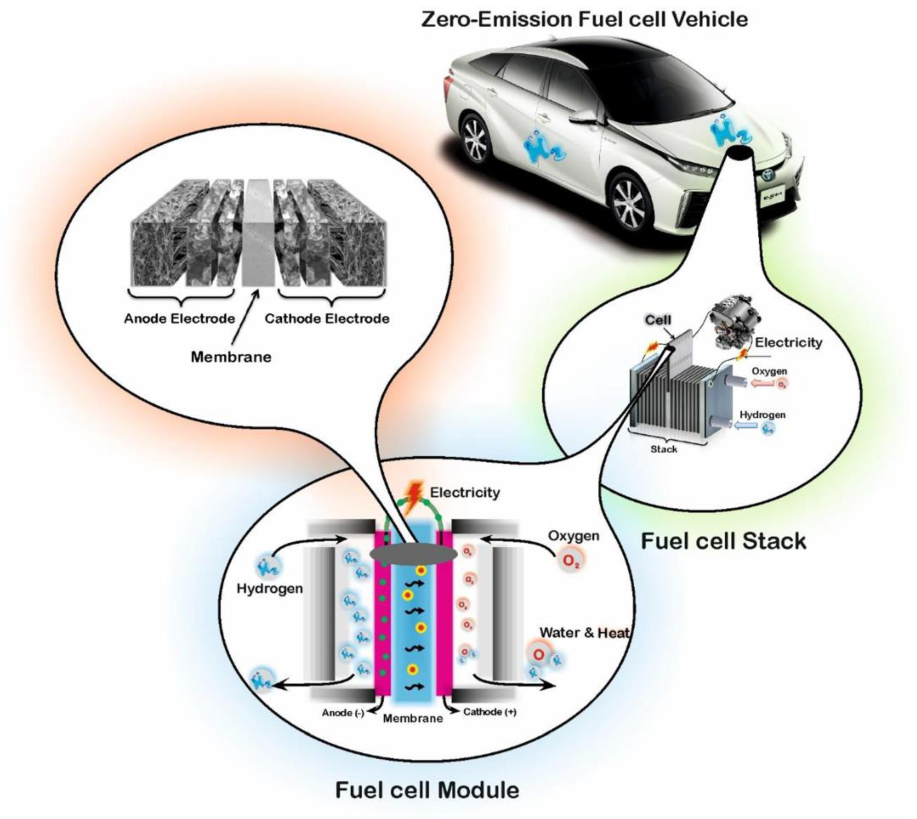
Figure 1. Schematic of a PEM fuel cell used in hydrogen fuel cell vehicles [16] (reproduced with permission from reference [16], Elsevier Ltd., 2021).
Energies 16 04772 g001
Figure 2. Degradation modeling methods.
Energies 16 04772 g002
Figure 3. ANN topology [7] (reproduced with permission from reference [7], Elsevier Ltd., 2021).
Energies 16 04772 g003
Figure 4. BP neural network [62] (reproduced with permission from reference [62], Elsevier Ltd., 2019).
Energies 16 04772 g004
Figure 5. The CSA-WNN-based PEMFC degradation prognosis [64] (reproduced with permission from reference [64], Elsevier Ltd., 2021).
Energies 16 04772 g005
Figure 6. Conventional RNN (a) and LSTM memory cell (b) [65] (reproduced with permission from reference [65], Elsevier Ltd., 2018).
Energies 16 04772 g006
Figure 7. The architecture of the LSTM memory cell [65] (reproduced with permission from reference [65], Elsevier Ltd., 2018).
Energies 16 04772 g007
Figure 8. RUL prognostic framework for PEMFCs based on LSTM RNN [67] (reproduced with permission from reference [67], Elsevier Ltd., 2019).
Energies 16 04772 g008
Figure 9. Proposed AE-LSTM prognostic approach [68] (reproduced with permission from reference [68], Elsevier Ltd., 2022).
Energies 16 04772 g009
Figure 10. The framework for establishing a degradation prediction model [72] (reproduced with permission from reference [72], Elsevier Ltd., 2021).
Energies 16 04772 g010
Figure 11. Multi-layer dilated CNN [73] (reproduced with permission from reference [73], Elsevier Ltd., 2022).
Energies 16 04772 g011
Figure 12. Combined convolutional neural network (CNN) and bi-recurrent neural network (BiRNN) model [74] (reproduced with permission from reference [74], Elsevier Ltd., 2022).
Energies 16 04772 g012
Figure 13. The proposed CNN-LSTM architecture [75] (reproduced with permission from reference [75], Elsevier Ltd., 2022).
Energies 16 04772 g013
Figure 14. ESN architecture.
Energies 16 04772 g014
Figure 15. The structure of echo state network [80] (reproduced with permission from reference [80], Elsevier Ltd., 2020).
Energies 16 04772 g015
Figure 16. Fuzzy logic membership function [87] (reproduced with permission from reference [87], Elsevier Ltd., 2019).
Energies 16 04772 g016
Figure 17. A typical ANFIS architecture [8] (reproduced with permission from reference [8], Elsevier Ltd., 2013).
Energies 16 04772 g017
Figure 18. SSA-DGP-based RUL prediction framework for PEMFC [95] (reproduced with permission from reference [95], Elsevier Ltd., 2020).
Energies 16 04772 g018
Figure 19. Implementation architecture of DP-based methods [96] (reproduced with permission from reference [96], Elsevier Ltd., 2022).
Energies 16 04772 g019
Disclaimer/Publisher’s Note: The statements, opinions and data contained in all publications are solely those of the individual author(s) and contributor(s) and not of MDPI and/or the editor(s). MDPI and/or the editor(s) disclaim responsibility for any injury to people or property resulting from any ideas, methods, instructions or products referred to in the content.