Article

Simulation and Analysis of Proppant Transport Patterns in Wellbore-Fracture Systems

1
Unconventional Oil and Gas Science and Technology Research Institute, China University of Petroleum (Beijing), Beijing 102249, China
2
Engineering Technology Branch, CNOOC Energy Development Co., Ltd., Tianjin 300452, China
3
Xinjiang Taiqi Petroleum Technology Co., Ltd., Karamay 834000, China
*
Author to whom correspondence should be addressed.
Energies 2023, 16(11), 4421; https://doi.org/10.3390/en16114421
Submission received: 5 April 2023 / Revised: 3 May 2023 / Accepted: 25 May 2023 / Published: 30 May 2023

Abstract

:
Staged multi-cluster fracturing of horizontal wells is one of the most important tools to achieve efficient development of unconventional oil and gas reservoirs. The multi-stage fracturing technique forms complex fractures with multiple clusters and branches in the formation, causing competing diversions leading to more complex proppant transport patterns, and the proppant placement method determines the flow conductivity of complex fractures, so it is necessary to investigate the proppant transport patterns in complex fractures. To address this issue, a field-scale geometric model is established for numerical simulation, and the multiphase flow diversion pattern in the wellbore, the proppant distribution pattern under different network conditions, and the optimization of different construction parameters are investigated. The results are obtained as follows: the distribution of solid and liquid phases in each cluster of the well conforms to the trend of variable mass flow; the proppant is distributed at the heel end in multiple clusters of fractures, and the sand and liquid are unevenly distributed among clusters of fractures, and the number of branching affects the proppant transport; through sensitivity analysis of the influencing factors, the pumping displacement, fracturing fluid viscosity and proppant particle size are optimized, and the construction parameters of 14 m3/min, 5 mPa·s, 70/140 mesh, 12% sand ratio are determined. This study has a certain guiding significance for the optimization of fracturing parameters in this block.

1. Introduction

Unconventional oil and gas refers to oil and gas resources that cannot be exploited by conventional methods and technologies, mainly including shale oil and gas, tight oil and gas, coal-bed methane and natural gas hydrate, etc. The amount of unconventional resources is huge, and the prospect of exploitation is very promising. Among them, unconventional oil and gas resources are more than 4~5 times conventional oil and gas resources and have become a strategic alternative energy source to conventional energy sources [1]. Staged multi-cluster fracturing of horizontal wells is one of the most important tools to achieve the efficient development of unconventional reservoirs. Unconventional oil and gas reservoirs are usually naturally fractured and are prone to form complex fracture networks after the multi-stage modification of horizontal wells. There is competition between fracture fluids and proppant at the branches of inter-cluster fractures and fractures in the same cluster, and there are differences in support amount and support effect. Whether the proppant can effectively and uniformly fill into the fracture becomes a key point in the staged multi-cluster fracturing of horizontal wells, which directly determines the transformation effect after fracturing. Therefore, mastering the distribution pattern of proppant in the fracture is very important to the success of multi-cluster fracturing in horizontal wells.
In recent years, there have been more studies on pure solid-liquid phase flow, reservoir fracture morphology and proppant transport in fractures [2,3,4,5,6,7,8,9,10,11,12,13,14,15,16,17,18,19,20,21,22,23,24,25,26,27]; the study of solid-liquid phase flow began with the study of single particle transport in fluids by Stokes (1851), Basset (1888), Boussinesq (1885) and Oseen (1927), et al. In recent years, Huang Shehua et al. [2] based on the Lagrangian equation, Tang Xuelin et al. [3] based on the Boltzmann equation, Bagnold et al. [4] based on turbulence intensity, and Yue Xianan et al. [6] based on the shear-collision (S-C) model have conducted representative studies on multi-particle transport in fluids; The study of reservoir fracture morphology began in 1987 with the theory of the influence of faults and laminae on fracture morphology proposed by N.R. Warpinski et al. [11], and in recent years, for the development process and morphology of reservoir fractures, Weng et al. [13] based on the UFM model, R. Wu et al. [14] based on the two-dimensional displacement discontinuity method, Zhang Shicheng et al. [15] based on true triaxial fracturing experiments, and Zhao Jinzhou et al. [16] based on fracture mechanics were simulated and studied; The study of proppant transport in fractures can be traced back to the physical simulation experiments conducted by Kern et al. using flat plates in 1959. The more common methods in recent years include physical and numerical simulations. Physical simulation methods include the studies conducted by Li Liang [21], Zhang Jing [22], Huifeng [23] and Wen Qingzhi et al. [24], and numerical simulation methods include those conducted by Zhou Desheng et al. [25], Zhan Yongping et al. [26] and Zhang Mingsheng et al. [27]. Based on previous studies, it is found that few existing studies on proppant transport during hydraulic fracturing can consider the transport of proppant in complex fracture networks, and there is a lack of consideration of the interaction between fracturing fluid and proppant, the flow and inter-cluster diversion of fracturing fluid and proppant in the wellbore-fracture, and realistic dimensional geometric models. To solve this problem, a field-scale geometric model was established for numerical simulation, and the multiphase flow diversion law in the wellbore, the proppant placement law under different seam network conditions, and the parameter optimization of different construction parameters were investigated.

2. Simulation Validation

This paper is based on the CFD software Fluent for simulation (https://www.ansys.com/products/fluids, accessed on 4 April 2023). Fluent is the most commonly used commercial CFD software for simulating complex flows in the incompressible to the highly compressible range. Fluent software has a wide range of applications and is not only highly stable but also highly accurate. Through the user’s own choice of numerical algorithm, the most stable and accurate solution can be obtained, up to second-order accuracy. Fluent numerical simulation software enables the simulation of solid-liquid two-phase flows and, thus, the study of fluid motion laws.
The most complex multiphase flow model in Fluent, the Eulerian model, is used in this paper; and the model in this paper is a fully turbulent state. In conjunction with this study, the fluid is flowing with an initial velocity in the horizontal direction, in addition to gravity perpendicular to the direction of fracture extension. The liquid-solid phases will be confused with each other in the model rather than just sliding against each other, so the standard k-ε turbulence model (Standard k-ε) was chosen.

2.1. Equation Used in Simulation

The equations for the Euler model and the Stand k-ε turbulence model chosen in this paper are shown below.
(1)
Euler model
The model is dominated by the volume fraction equation, the mass conservation equation and the momentum conservation equation.
① The volume fraction equation
The q-phase volume fraction Vq is calculated as:
V q = V   α q d V
where αq is determined by the following equation:
q = 1 n α q = 1
② The mass conservation equation
The equation for the conservation of mass in phase q is:
( α q ρ q ) t + · α q ρ q v q = p = 1 n m ˙ p q m ˙ q p + S q
where, v q —velocity of phase q;
m ˙ p q —mass transferred from phase p to phase q, m ˙ q p in the same way;
③ The momentum conservation equation
The conservation of momentum equation for phase q is:
α q ρ q v q t + · α q ρ q v q v q = α q p + · τ = q + α q ρ q g + p = 1 n R p q + m ˙ p q v p q m ˙ q p v q p + F q + F l i f t , q + F w l , q + F v m , q + F t d , q
where, τ = q —the stress-strain tensor of the q phase;
F q   ,     F l i f t , q ,     F w l , q ,     F v m , q ,     F t d , q q-phase volume force; q-phase buoyancy, lift force; q-phase wall action force; q-phase imaginary mass force; q-phase turbulent dispersion force;
R p q —interphase forces;
(2)
Standard k-ε turbulence model
The model is mainly controlled by the transport equations and other constants.
① The transport equations
p k t + p k u i x i = μ + μ t σ k k x j x j + G k + G b ρ ε Y M
ρ ε t + ρ ε u i x i = μ + μ t σ ε ε x j x j + C 1 ε ε k G k + G 3 ε G b C 2 ε ρ ε 2 k
where, k—turbulent kinetic energy;
Gk—turbulent kinetic energy generated by the mean velocity gradient;
Gb—turbulent kinetic energy generated by buoyancy;
YM—contribution of pulsating expansion to the total dissipation rate in compressible turbulent flows;
C, C—constants;
σε, σk—turbulent Prandtl number;
② Turbulent viscosity models
μ t = ρ C μ k 2 ε
where, Cμ—constant;
Common values for the constants in the above equations are C = 1.44, C = 1.92, Cμ = 0.09, σε = 1.3 and σk = 1.0.

2.2. Validation of Simulation Results against Experimental Results

The validity of the simulation method can be carried out by comparing the results with the physical simulation experiments conducted by YP Zhan et al. [26], as shown in Figure 1 and Figure 2.
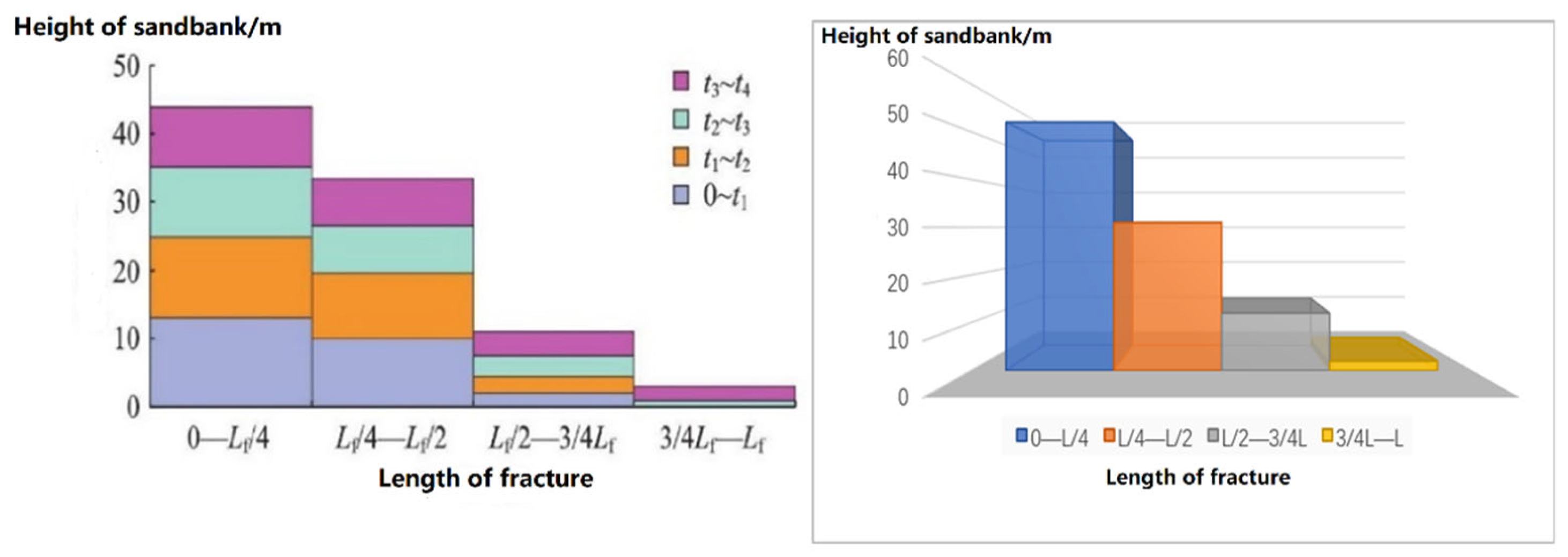
By comparing the experimental results with the fracture profile from the numerical simulation, Figure 1, it can be seen that the overall morphology of the sandbanks is relatively similar. As can be seen from Figure 2, the equilibrium height of the sandbank formed by proppant settlement under experimental conditions is 0.46 m, while in the numerical model validation results, the sandbank equilibrium height is 0.52 m. The difference may be due to the situation that with the same displacement, all of the proppant in the numerical simulation entered the fracture, whereas in the physical experiments, due to the need to pass through the pipeline before entering the fracture, this may have resulted in the proppant being left in the pipeline and not all entering the visible fracture device, resulting in slightly higher results in the numerical simulation tests than in the physical experiments.

3. Proppant Transport in The Wellbore

3.1. Methodology: Simulation Modle and Parameter Settings

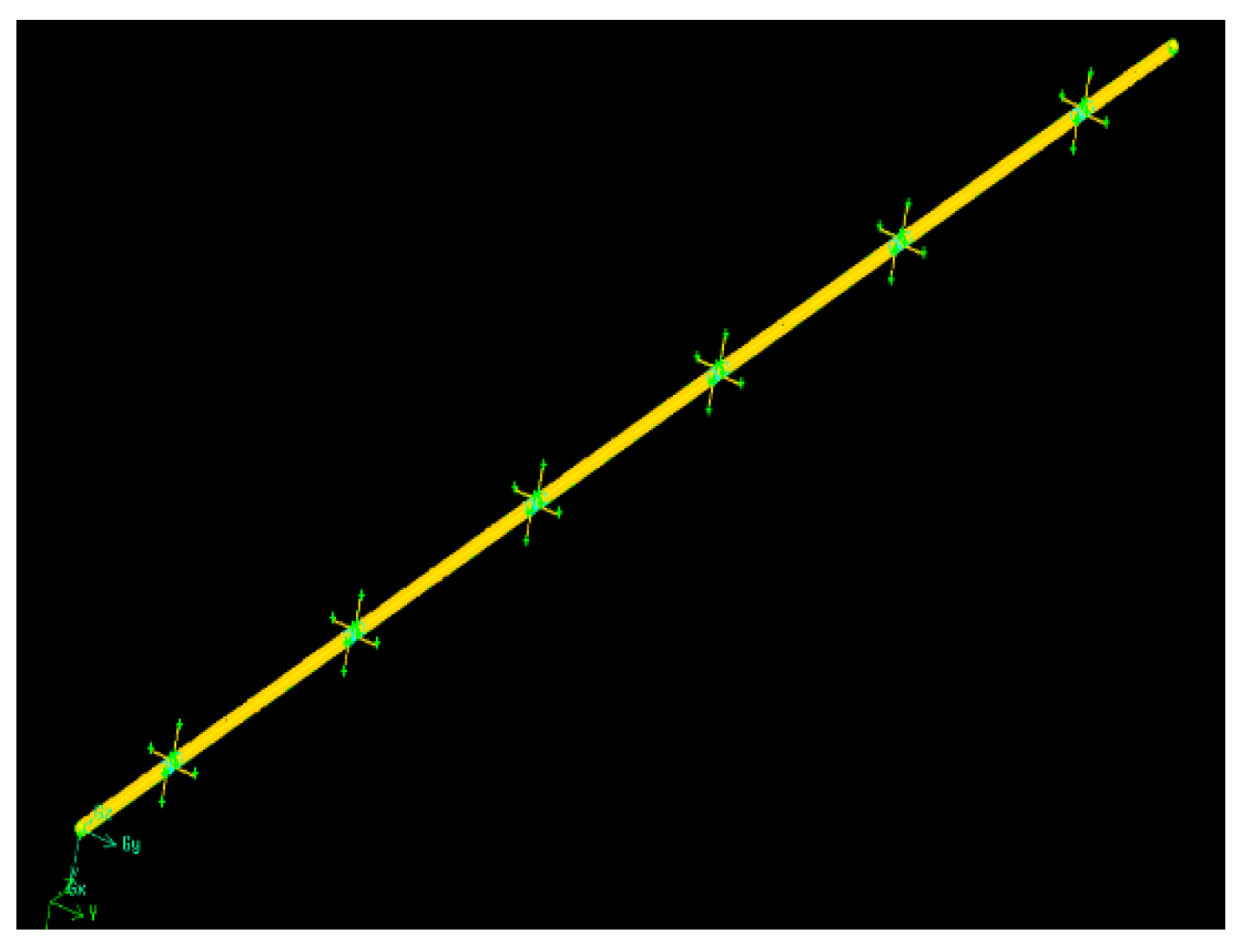
A horizontal wellbore model is established, the modeling schematic is shown in Figure 3, and its specific simulation parameters are shown in Table 1.
The grid encryption is laid out in variable density, with a grid accuracy of 0.03 at the borehole section, 0.01 at the perforation section and 0.005 at the perforation depth. The Eulerian multiphase flow model was used to simulate the two-phase flow in the wellbore, with the velocity inlet set at the entrance of the horizontal well and the inlet velocity obtained according to the initial discharge required for each group of calculations; the pressure outlet was set at the exit of each of the four clusters of horizontal good injection holes, with the pressure is the formation rupture pressure, which in this case is 55 MPa based on the geological background of the target block.

3.2. Discussion and Conclusions of Simulation Results

3.2.1. Proppant Distribution in The Wellbore

The simulation results were collated, and the volume fraction of proppant contained in the wellbore at each cluster location profile at the simulated flow time of 5 min was analyzed first, as shown in Figure 4. In Figure 4, the higher the volume fraction of the support agent, the darker the colour, from small to large in the order of blue, green, yellow and red.
As can be seen from the transitional trend of the proppant concentration distribution in each cluster in Figure 4, the proppant concentration is at a low level in the two clusters at the heel end, and the proppant concentration in the middle three clusters is not too different but higher than at the heel end, and the proppant concentration in the first cluster at the toe end shows that more severe deposition has occurred.

3.2.2. Solid and Liquid Phase Flow Distribution of Each Cluster

For the purpose of collation, good horizontal simulations were re-run for four of the perforation clusters while keeping other parameters constant, and the cumulative solid and liquid phase outflow mass data for each cluster at a simulated flow time of 30 min were collated and analyzed, as shown in Figure 5, Figure 6 and Figure 7.
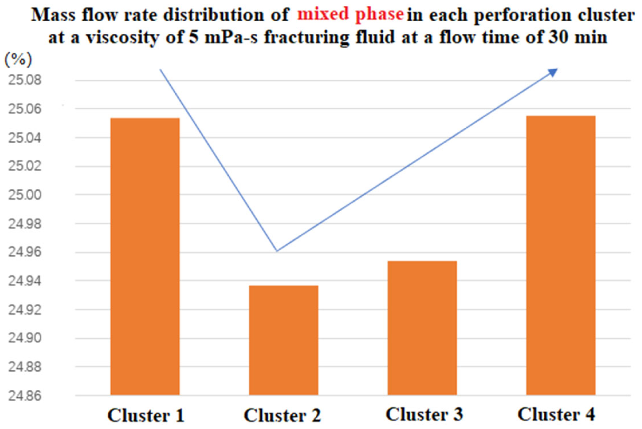
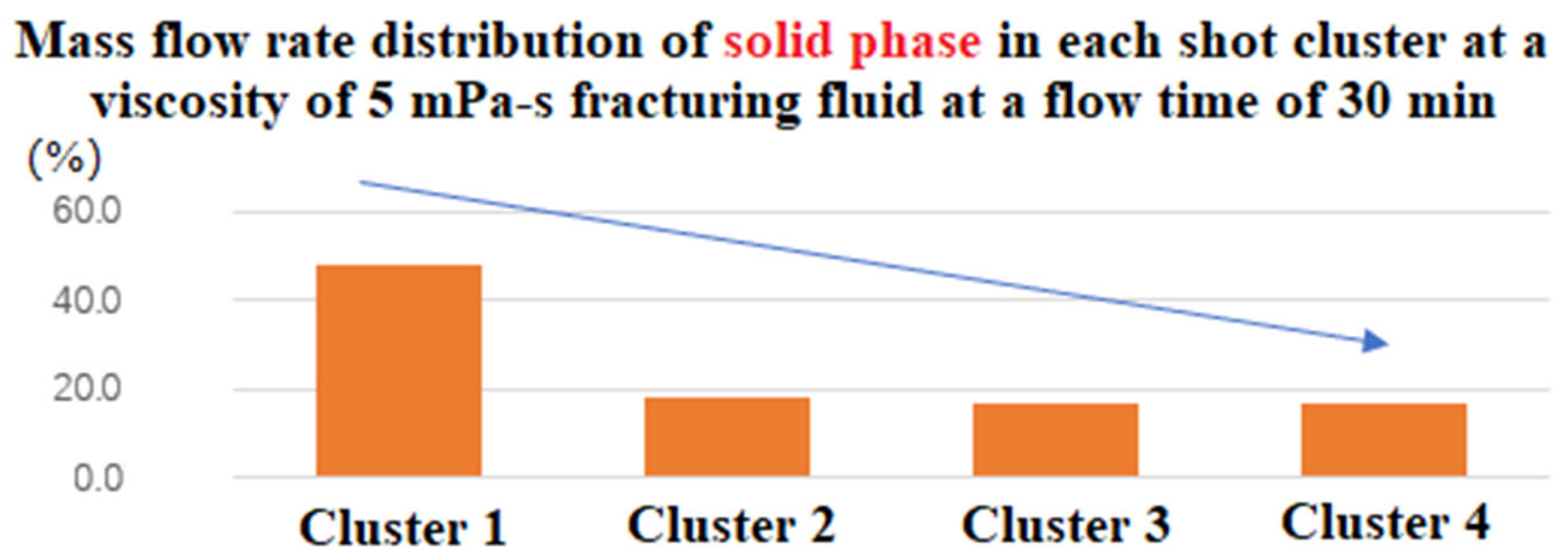
According to the mixed-phase mass flow rate distribution of each cluster (Figure 5), it is found that the mixed-phase flow rate of clusters 1 to 4 tends to decrease and then increase in the wellbore; the solid and liquid phases have the highest flow rate at the entrance of the wellbore and at the end of the wellbore, while the flow rate of the middle cluster is lower; according to the liquid-phase mass flow rate distribution of each cluster (Figure 6), it is found that the liquid-phase mass flow rate tends to increase along the wellbore from the entrance to the end of the wellbore. The solid phase mass flow rate tends to decrease along the wellbore from the inlet to the end of the wellbore, which should be due to the situation that the perforation clusters are not blocked, and deposits are formed at the end of the wellbore, which is why the mixed phase mass flow rate in cluster 1 increases. This conclusion corresponds to the solid phase content of the profile at each cluster of the wellbore.
As a result, the proppant will form deposits inside the wellbore near the toe end cluster, which will result in a relatively low mass of proppant entering the toe end fracture, and a high solid phase flow rate in the heel end cluster of the wellbore, which will result in a high dose of proppant entering the heel end fracture.

4. Wellbore-Complex Fractures Network Proppant Transport

4.1. Geological Parameters Research

The simulation was carried out in the context of a Carboniferous reservoir in a block in China, so some geological parameters were investigated and applied.
The Carboniferous reservoir in this area is located approximately 14 km northeast of the city of Karamay, bounded by the North Heilianshan Fault to the northwest and the Karamay Fault to the southeast, with a length of approximately 11 km from east to west and a width of approximately 3 km from north to south.
Lithologically, the Carboniferous System in this area is mainly a set of dark grey and dark grey-green basaltic volcanic rocks, with the main lithologies being: basalt, altered basalt, volcanic breccia, volcanic breccia lava and andesite. Basaltic lithologies are the main lithologies in this area, and according to the deep Carboniferous imaging logging data, the thickness of basaltic lithologies accounts for 57.3% of the deep Carboniferous drilling and uncovering thickness.
In terms of reservoir physical properties, according to the core data, the basalt reservoir has an average porosity of 6.2% and permeability of 1.25 mD; the volcanic breccia reservoir has an average porosity of 9.7% and permeability of 1.8 mD, which is a low-porosity, extra-low-permeability reservoir. As the distance from the top of the Carboniferous System increases, the reservoir’s physical properties gradually deteriorate, as shown in Figure 8.
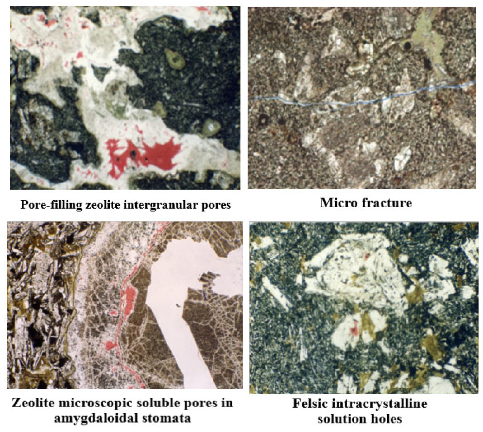
In terms of reservoir space types, the Carboniferous reservoir space is a dual pore-fracture medium type. The pore types are mainly intergranular pores, intergranular solution pores, solution pores, pore residual pores and microfractures, as shown in Figure 9. The fracture types are mainly oblique intersections, reticulation joints, filling joints, straight split joints and induced joints. Based on the observation of a core from a well in the block, most of the different types of fractures are filled with calcite, siliceous and chlorite.

4.2. Simulation of Proppant Distribution within Fracture in a General Fractures Network

This subsection simulates and discusses the distribution of proppant within fractures in a general fracture network

4.2.1. Methodology: Simulation Modle and Parameter Settings

Modeled the wellbore-complex fractures network, divided into three levels of fractures, and there are 3 clusters in total. The specific modeling situation and parameter settings are shown in Figure 10 and Table 2. In Figure 10, the green colour is the boundary line of the model and the yellow part is the colour of the mesh after the 3D model has been meshed.
The gridding was carried out using Gambit software v.2.2. and according to a simple to a complex pattern. The fracture is closer to the wellbore-fracture coupling; the higher the grid accuracy and the greater the number of grids. The furthest point of the fracture was meshed at 0.2, the wellbore at 0.05 and the rest of the fracture was meshed between 0.2 and 0.05. Hex/Wedge meshing was used at the wellbore, and Hex meshing was used for the majority of the fractures.

4.2.2. Discussion and Conclusions of Simulation Results

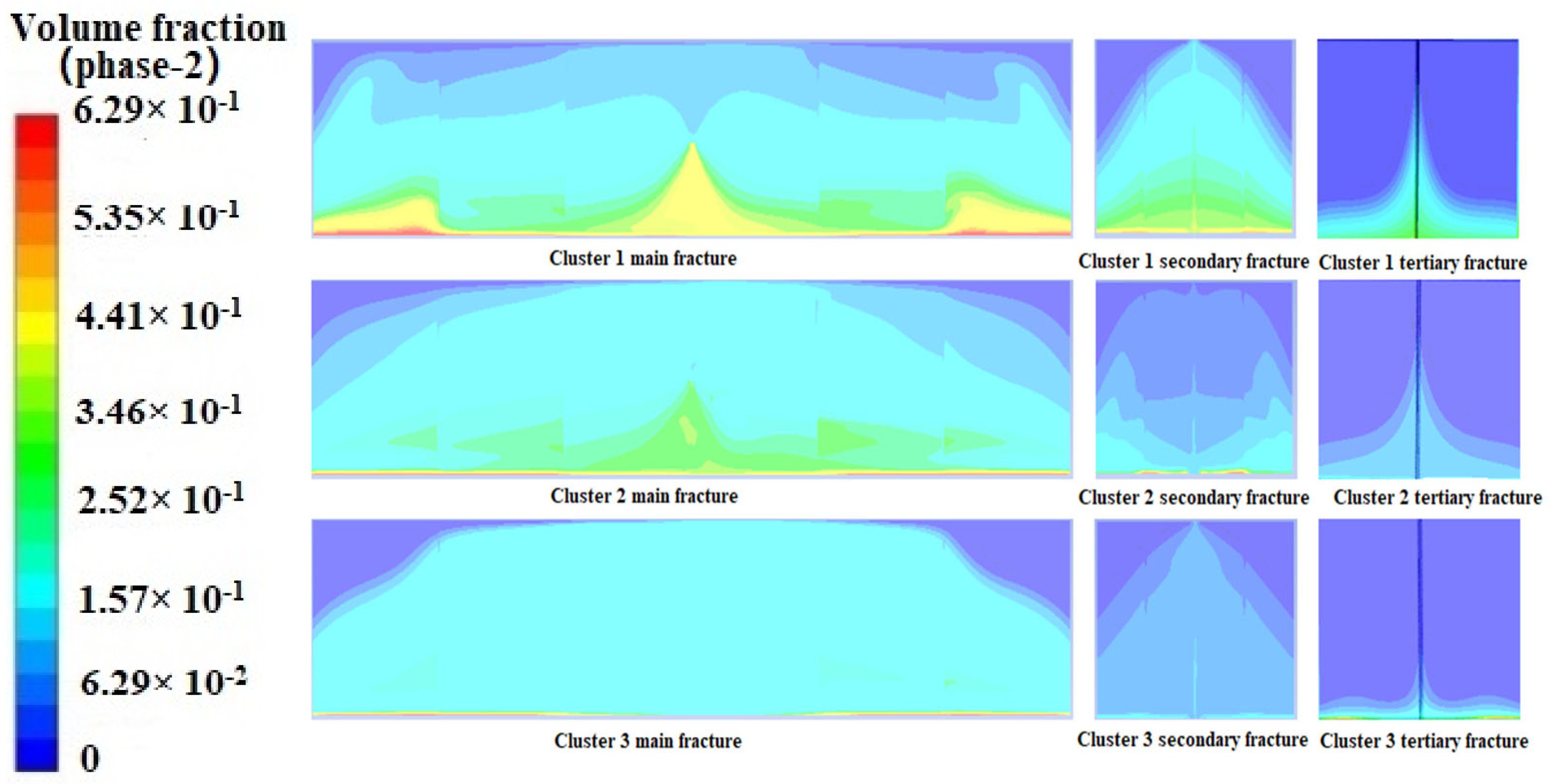
The distribution of proppant within each main, secondary and tertiary fracture is collated, and the situation is shown in Figure 11.
As can be seen from the simulation results in Figure 11, there are differences in the proppant distribution in each cluster of fractures within the three-stage fracture model, with the highest proppant concentration in the first cluster of fractures near the entrance and the lowest proppant concentration in the third cluster of fractures at the end of the wellbore. This conclusion is consistent with that obtained from proppant simulations within the wellbore.
And it can be seen in Figure 11 that the proppant mainly enters into the main fracture, the proppant placement in the secondary fracture is much less than in the main fracture, there is only little proppant distribution in the tertiary fracture, the specific data of the cumulative volume flow rate of proppant in each cluster of fractures are shown in Figure 12.
From the cumulative flow rate of proppant into each cluster of fractures in Figure 12, it can be seen that the cumulative volume ratio of proppant in clusters 1, 2 and 3 within the main fracture is approximately 2.7:2.2:1; the cumulative volume fraction of proppant in clusters 1, 2 and 3 within the secondary seam is 3.5:1.5:1, and the cumulative volume ratio of proppant within the tertiary seam is 2:1:1. Between clusters, the non-uniform trend of proppant within the main fracture, within the secondary fracture and within the tertiary fracture becomes more and more obvious.

4.3. Simulation under Different Complex Fractures Network Conditions

This subsection simulates and discusses the distribution of proppant within the fracture for a variety of fracture network conditions.

4.3.1. Methodology: Parameter Settings

A number of different fracture networks are modeled; the angles between the main and secondary fractures and between the secondary and tertiary fractures are shown in Table 3.
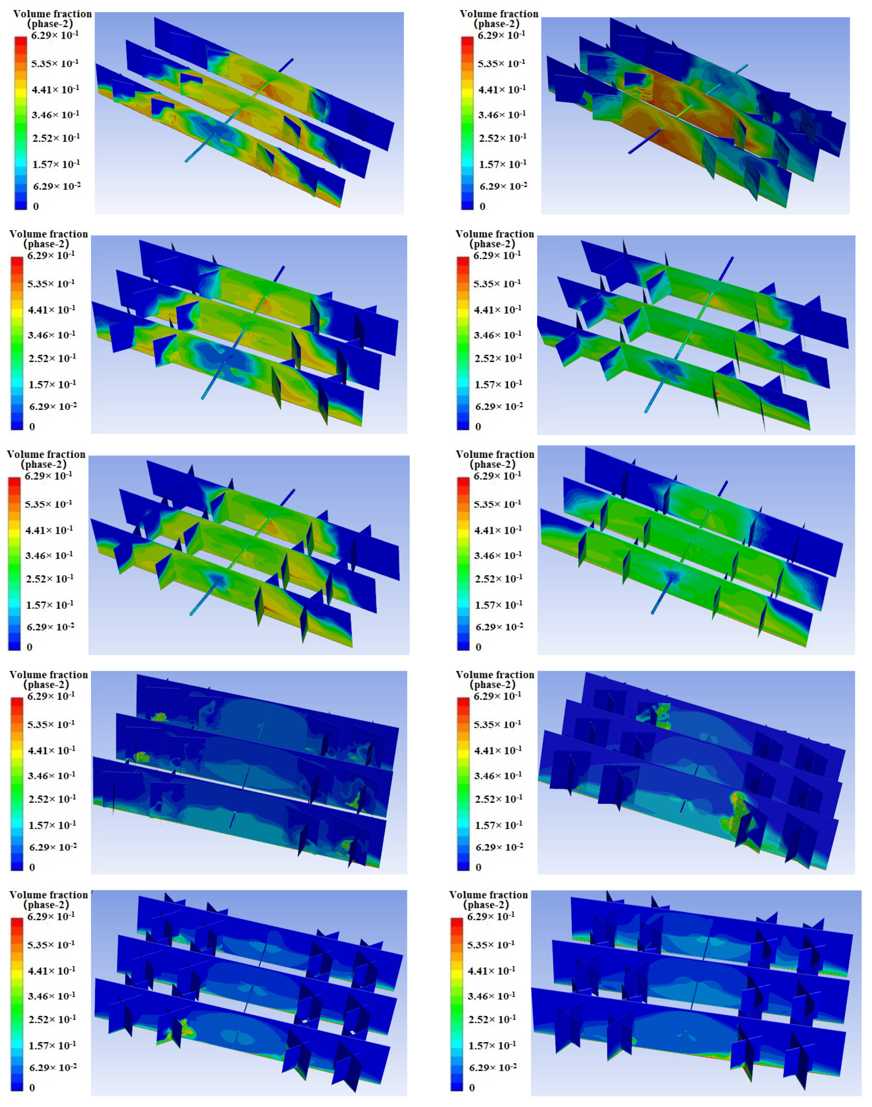
The simulations are shown in Figure 13.
The results of many models are consistent with the conclusion that the proppant is more likely to be distributed in the heel-end fractures and that the proppant fraction in the branch fractures decreases with the stage of fracture increases, all conforming to the previous conclusions.

4.3.2. Discussion and Conclusions of Simulation Results

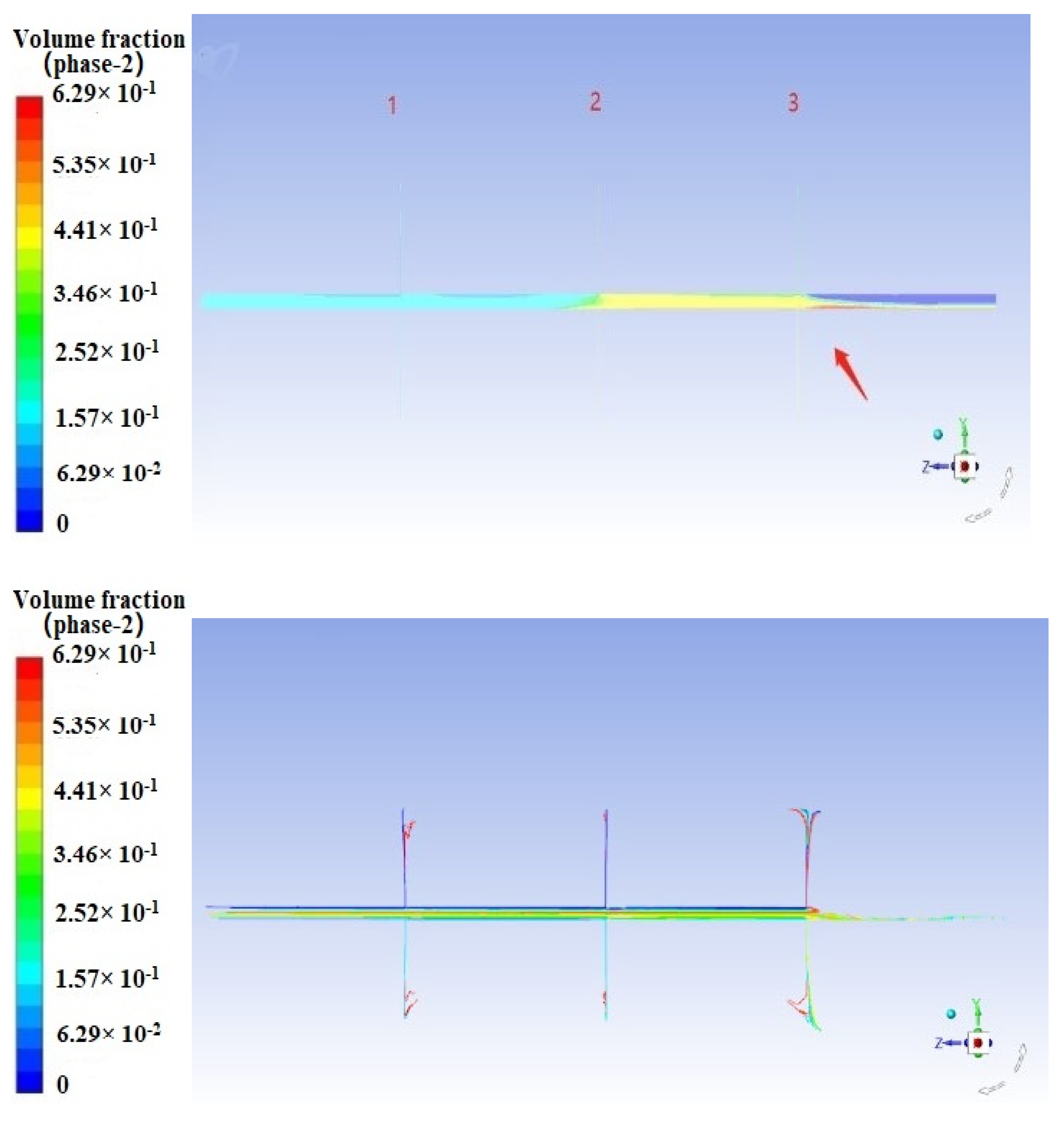
In conjunction with the previous conclusions, the proppant distribution and proppant flowlines within the wellbore in the simulation results are viewed; the results are shown in Figure 14. In this figure, the number of 1, 2, 3 indicates the location of the perforation clusters.
According to Figure 14, it was found that the proppant formed a high-concentration distribution zone in the wellbore between the second and third clusters, which impeded further proppant flow and made it more difficult for the proppant to flow to the toe end side. Subsequent numbers of newly injected proppant then entered the first fracture more often. As the injection time increases, proppant transport gradually stabilizes, and the proppant concentration in the heel-end fracture is significantly higher than that in the toe-end fracture.

5. Parameter Optimisation Analysis

A general wellbore-main fracture model with 3 clusters is established and used to carry out sensitivity analysis of pumping displacement, fracturing fluid viscosity and proppant particle size during fracturing, and to carry out parameter optimization.

5.1. Basic Parameter Settings

The model geometry is a wellbore and multi-cluster fracture, and the model dimensions are the same as the actual construction. The specific parameter settings are shown in Table 4.

5.2. Optimization of Pump Displacement

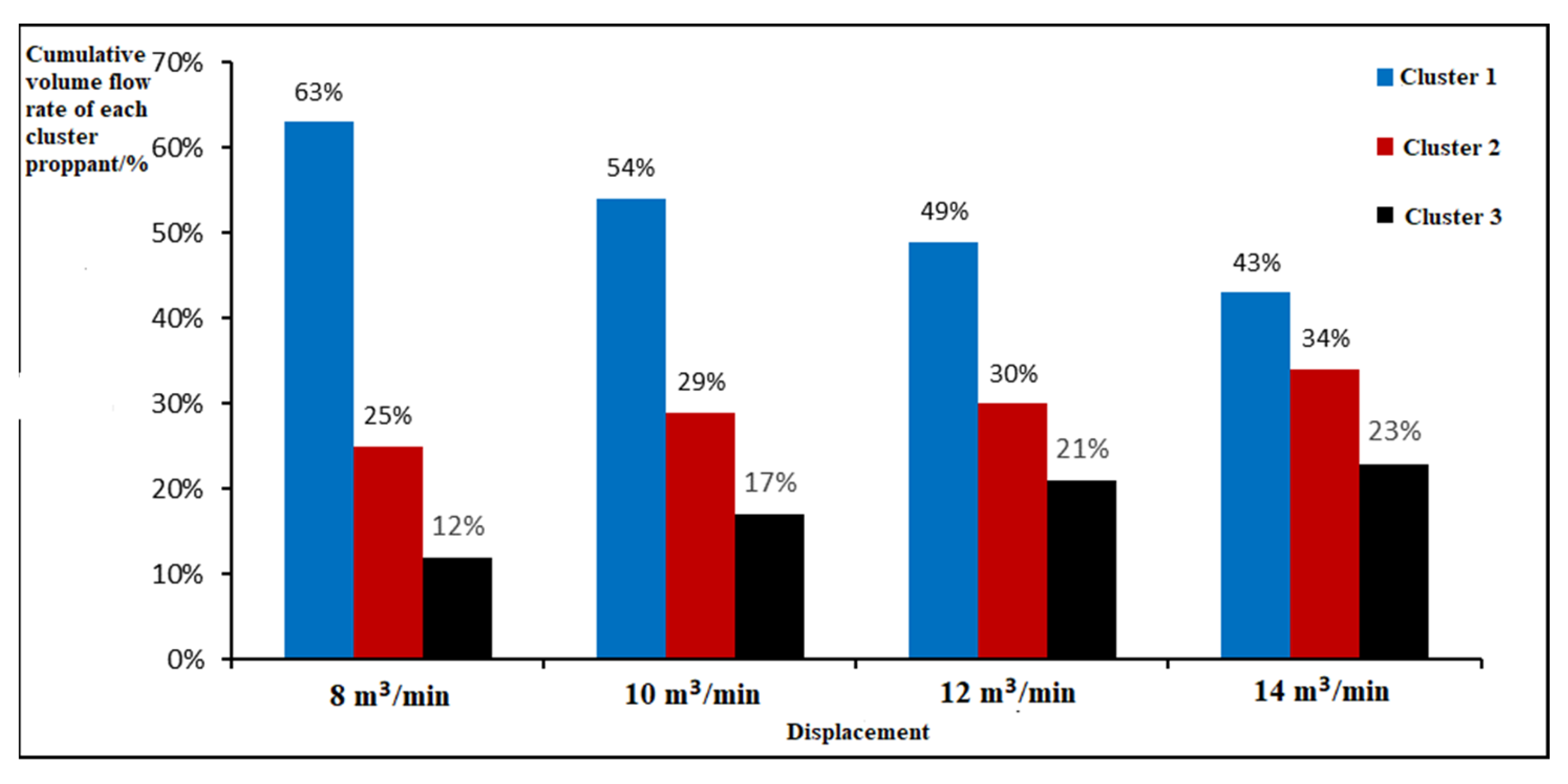
The pumping displacement is one of the important factors affecting proppant transport during proppant settlement. On the basis of the parameters, a controlled variable method was used to simulate and compare the effect of different displacements on proppant settlement under clear water fracturing conditions at four displacements of 8 m3/min, 10 m3/min, 12 m3/min and 14 m3/min. The resulting data are collated as shown in Figure 15 and Figure 16.
The cumulative flow rate of proppant into each fracture cluster in Figure 15 shows that the proppant volume ratio in the three fracture clusters is approximately 5.25:2.1:1 at 8 m3/min displacement, 3.2:1.7:1 at 10 m3/min displacement, 2.3:1.4:1 at 12 m3/min displacement and 1.9:1.5:1 at 14 m3/min displacement. The cumulative flow of fluid into each fracture cluster in Figure 16 shows that the proppant volume ratio in the three fracture clusters is approximately 1:1.7:2.1 at 8 m3/min displacement, 1:1.3:1.8 at 10 m3/min displacement, 1:1.4:1.7 at 12 m3/min displacement and 1:1.2:1.3 at 14 m3/min displacement.
The distribution of proppant and fluid intake within each cluster fracture is greatly improved with increasing displacement, and the distribution of proppant and fluid intake within each cluster fracture is more uniform at larger displacements. In summary, the use of a high displacement results in a higher concentration of proppant and a more even distribution between clusters, which facilitates the effective support of all clusters of fractures, and therefore a displacement of 14 m3/min is recommended.

5.3. Optimisation of Fracturing Fluid Viscosity

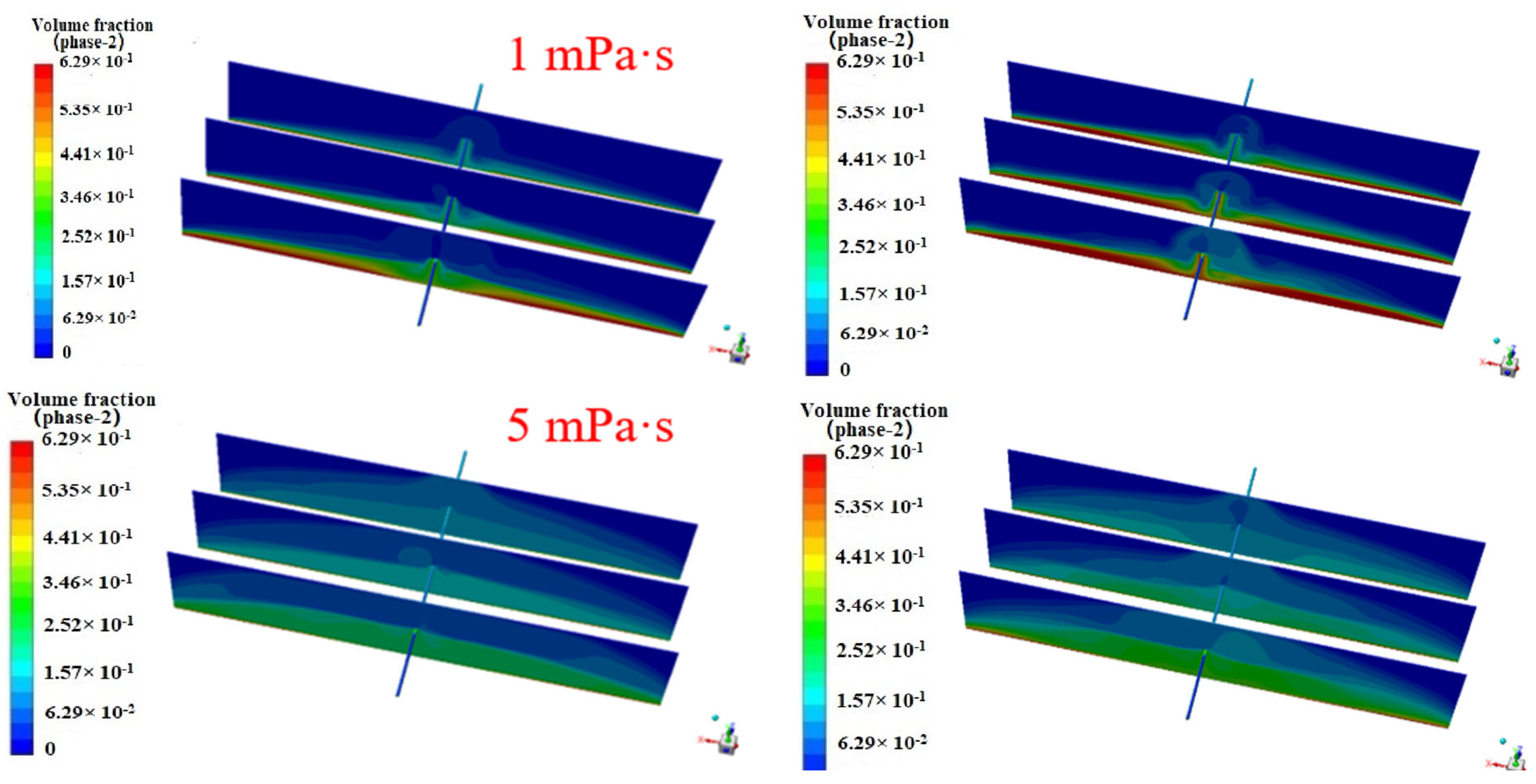
On the base parameters, simulations are carried out to compare the effect of four fracturing fluid viscosities, 1 mPa·s, 5 mPa·s, 10 mPa·s, 20 mPa·s and 80 mPa·s, on the proppant placement effect through using the controlled variable method. The resultant data are collated as shown in Figure 17.
As can be seen in Figure 17, there is no clear linear relationship between the increase in fracturing fluid viscosity and the distribution of proppant within each cluster. In contrast, the proppant distribution ratio between clusters is more balanced for 1 mPa·s and 5 mPa·s viscosities. However, the sandbank placement height in the fractures is limited at low viscosities, as shown in Figure 18.
In summary, considering the proppant placement effect and the proppant distribution ratio between clusters, it is considered that the 5 mPa·s viscosity fracturing fluid is more effective.

5.4. Optimisation of Proppant Particle Diameter

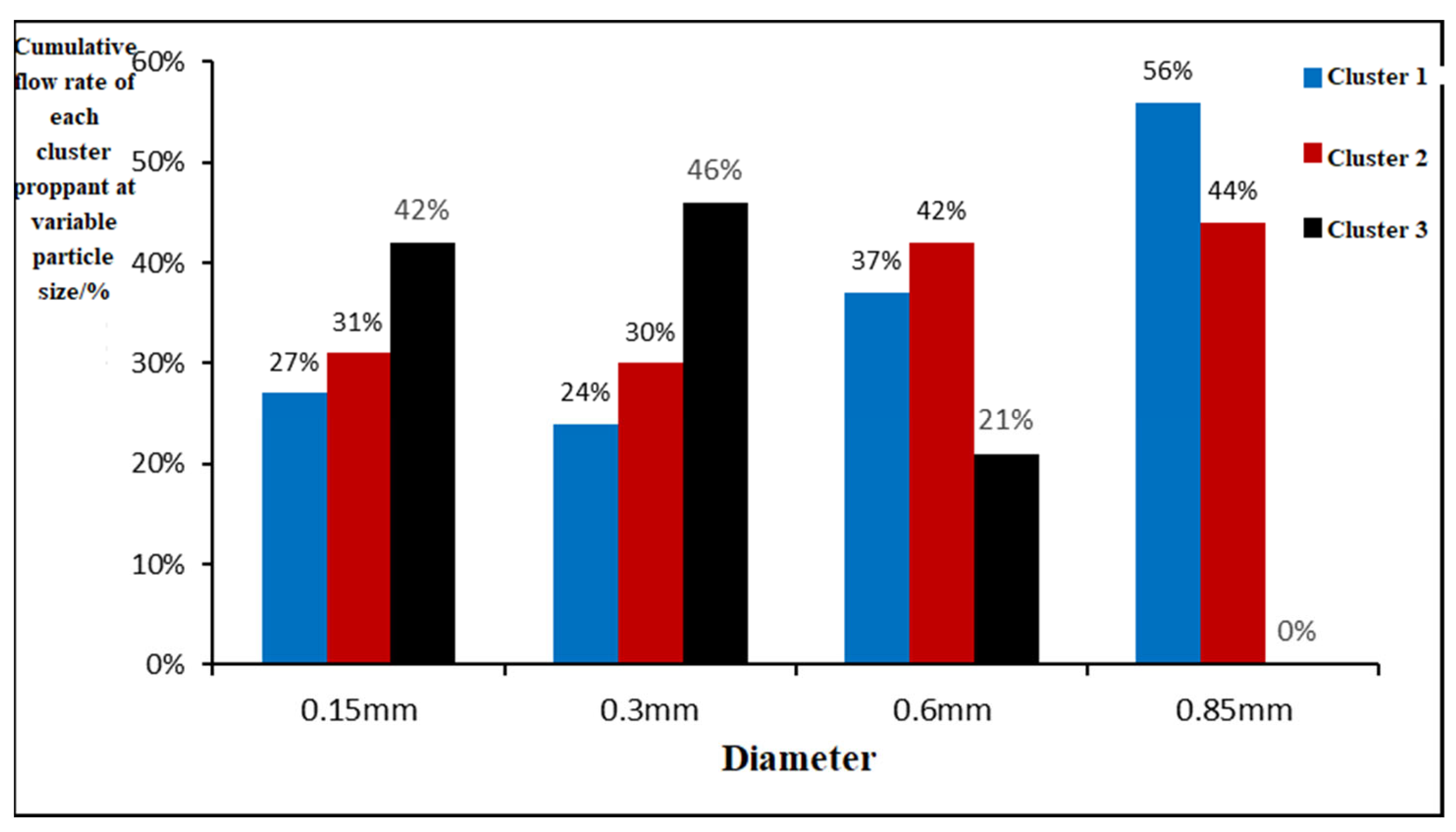
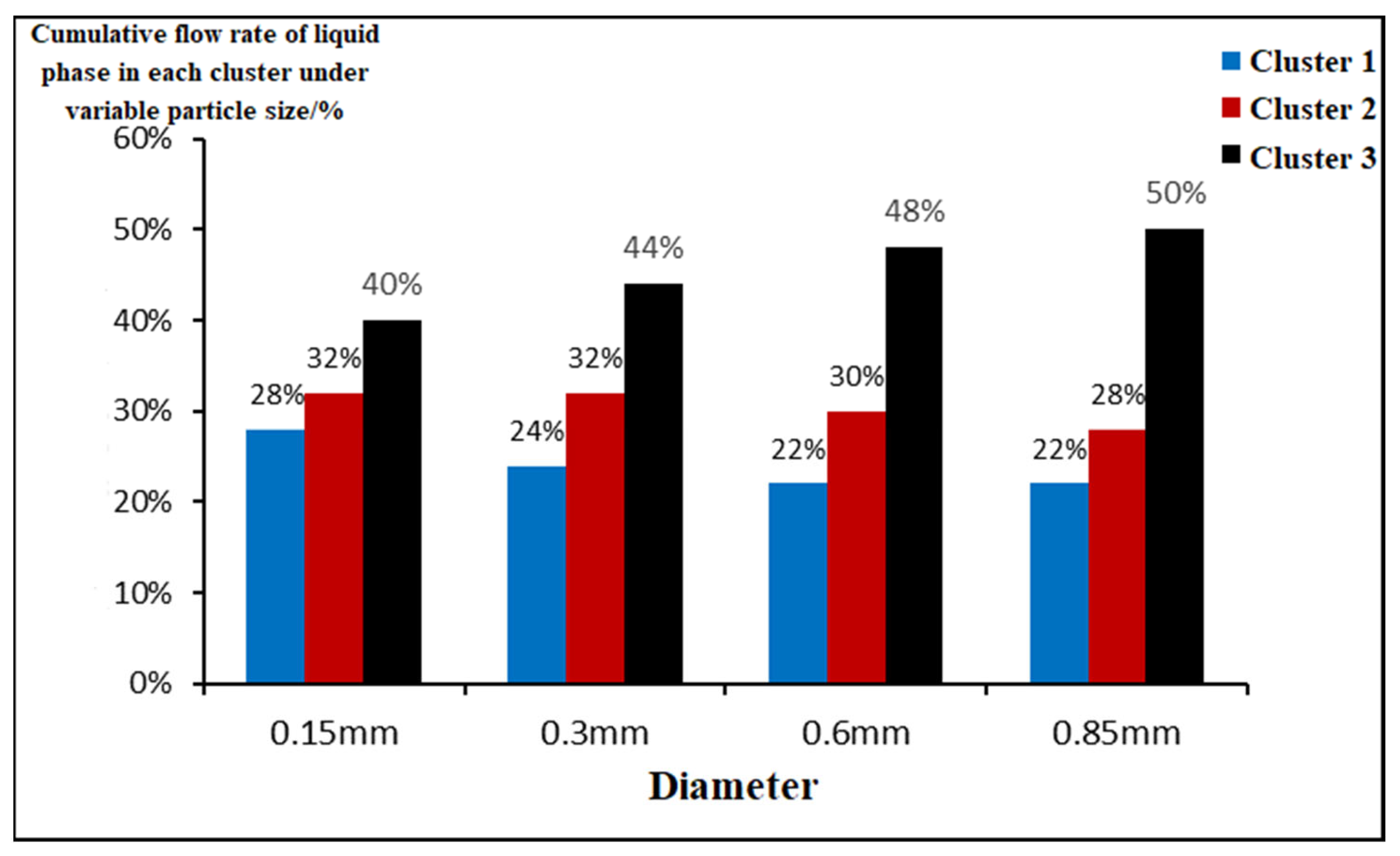
The particle size composition of the proppant determines the support effect of the proppant in the fracture and the level of fracture conductivity. Fractures filled with larger particle size proppant have higher permeability and better conductivity but also have problems with large particles, difficult transport and easy sand blockage [27]. Therefore for the preferential selection of proppant in complex fractures, the influence of proppant particle size on the proppant transport effect must be taken into account.
On the base parameters, simulations are carried out to compare the effect of four proppant particle sizes, 20 mesh, 20/40 mesh, 40/70 mesh and 70/140 mesh, on the proppant placement effect using the controlled variable method. The resultant data are collated as shown in Figure 19 and Figure 20.

5.5. Optimisation of Sand Ratio

The effect of sand ratio on proppant particle settling is mainly manifested in two aspects: a high sand ratio is equivalent to injecting more proppant, and the more sand ratio increases, the more obvious the interparticle interference settling phenomenon; on the other hand, an increase in the sand ratio is equivalent to increasing the density and viscosity of the fracturing fluid, and the settling rate of proppant will decrease with the increase in viscosity of the fracturing fluid. The sand ratio has less influence on the overall laying pattern of the proppant sand dike but has more influence on the time to reach the equilibrium height of the sand dike and the height of the leading edge of the sand dike.
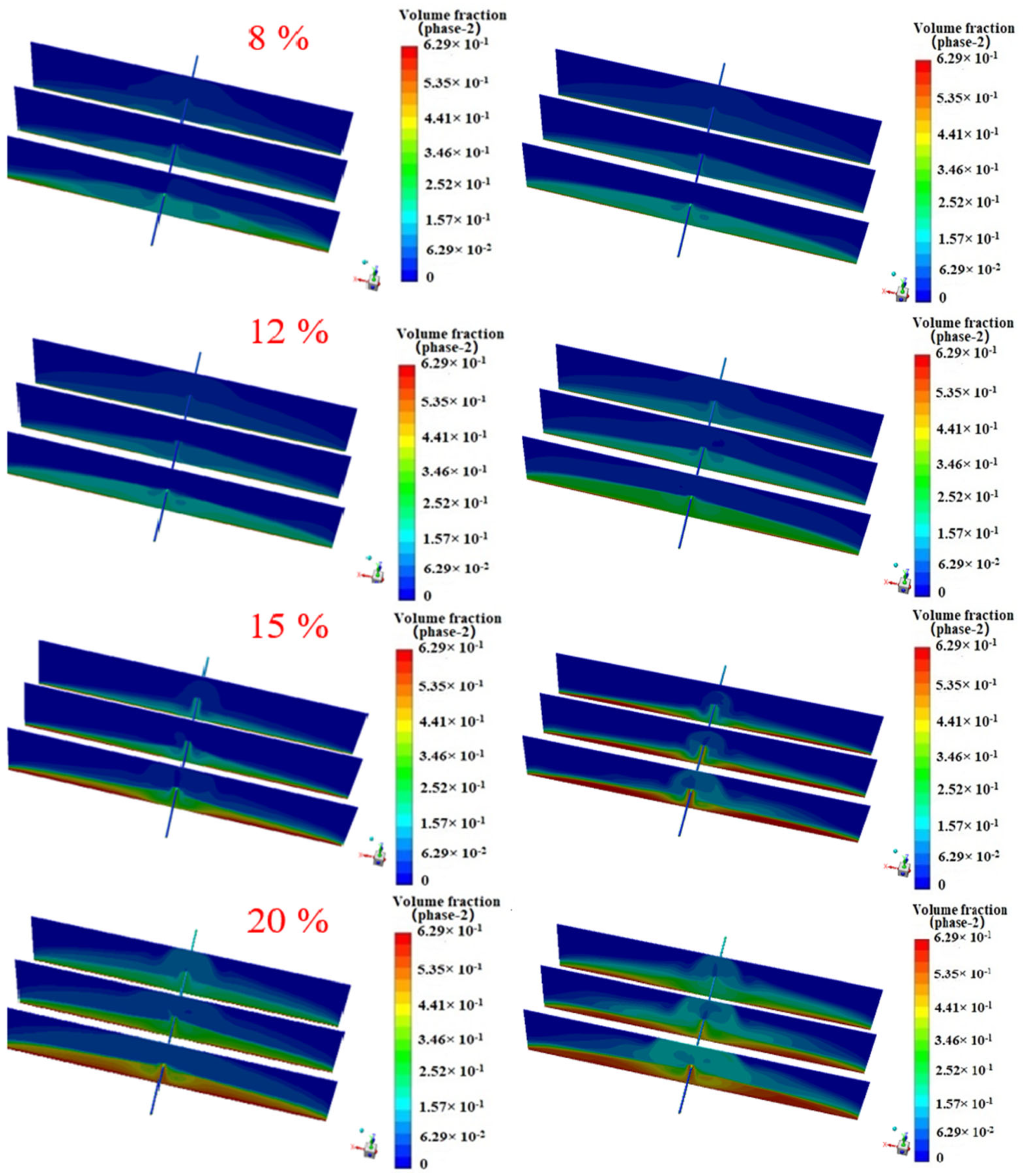
As the Eulerian model is used for the calculations, changing the sand ratio with a constant pump displacement is equivalent to changing the volume of the proppant injected. Comparing the 8%, 12%, 15% and 20% sand ratios, the results in Figure 21 show that the sand ratio has a greater effect on the equilibrium height of the sand dike, with higher sand ratios having a higher equilibrium height of the sand dike in each cluster within the fracture, while higher sand ratios are more likely to settle at the bottom. The proppant within each cluster of fractures tends to enter the main fracture in the first cluster near the well, with a large difference in proppant concentration between clusters.
At the same time, the sand ratio is calculated to have little effect on the proppant distribution ratio within each cluster. The proppant concentration ratio in each cluster is approximately 2.8:1.8:1. Therefore, a 12% sand ratio was used in the fracturing design, taking into account the economics and placement effect.

5.6. Comparison of the Practical Application of Optimised and Conventional Parameters

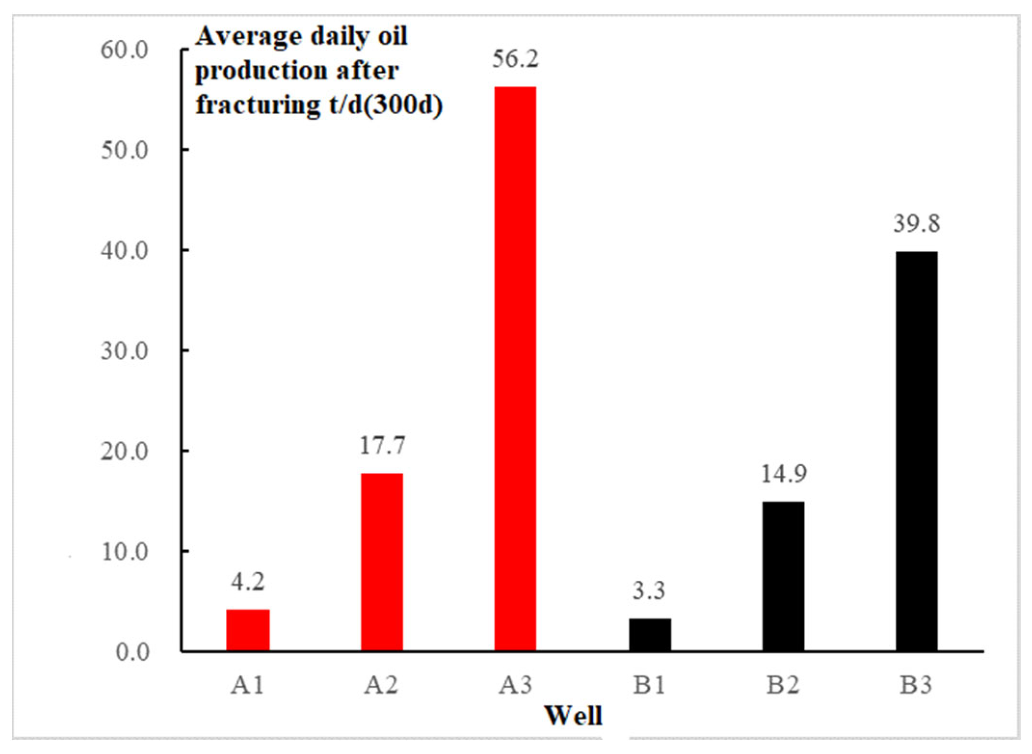
Based on the study of the factors influencing proppant transport, the fracturing design of the target block was optimized by combining the effects of different fracturing process parameters on proppant transport. A combination of quartz sand proppant, 70/140 mesh proppant and 5 mPa·s viscosity slick water fracturing fluid was used to optimize the fracturing design for the three wells in the target block. The fracturing in the target block was carried out at a discharge rate of 12–14 m3/min, with a maximum sand concentration of 280 kg/m3 and an average sand ratio of 12%, with a 100% fracturing success rate. The fracturing design parameters for the three wells in the target block are shown in Table 5.
The target block reservoir is influenced by natural fractures and the characteristics of the Carboniferous reservoir, and the post-pressure production capacity varies greatly. The daily oil production in this well area ranged from 4.2 to 56.2 t/d at 300 days post-pressure, with an average of 26.03 t/d.
From Figure 22, it can be concluded that the three wells A1–A3 fractured with optimized parameters and produced an average of 26.03 t/d of oil per day, while the three wells B1–B3 fractured with conventional fracturing produced an average of 19.33 t/d of oil per day, an increase of 34.7%. The fracturing design by complex fracture proppant transport simulation and parameter optimization has achieved a good production increase.

6. Conclusions

(1)
The simulation results concluded that the sand and fluid inside the horizontal wellbore during fracturing had a variable mass flow pattern with asynchronous distribution, and the proppant accumulation phenomenon inside the wellbore formed by this pattern led to the uneven distribution of proppant inside the fracture. The specific situation is as follows: The distribution of proppant and fluid inside the horizontal wellbore was not synchronized during fracturing, with the liquid phase gradually decreasing from the heel end to the toe end and the solid phase gradually increasing from the heel end to the toe end; the proppant formed deposits on the toe end side of the wellbore, causing poor proppant circulation, resulting in less proppant entering the toe end side of the fracture and more entering the heel end side of the fracture.
(2)
The simulation results conclude that the location of the perforation clusters and the number of fracture stages during fracturing have an important influence on the proppant distribution. The specific situation is as follows: During fracturing, the fracture proppant at the heel side of the complex fracture network was higher, and the fracture proppant at the toe end was lower, which is consistent with the findings of the in-bore simulation.
(3)
The preferred parameters derived from the simulations have been applied in real-life fracturing projects; it obtained substantially better production rates than the production of those wells, which are constructed with conventional fracturing parameters. Preferred parameters include pumping displacement, fracturing fluid viscosity, proppant particle size and sand ratio. 14 m3/min, 5 mPa·s, 40/170 mesh and 12% sand ratio were identified as the preferred construction parameters.

Author Contributions

Methodology, J.Z.; Investigation, Y.L.; Data curation, H.Y. and X.G.; Writing—original draft, Y.L. and H.Y.; Writing—review & editing, J.Z.; Supervision, J.Z. and X.G. All authors have read and agreed to the published version of the manuscript.

Funding

This research received no external funding.

Data Availability Statement

The data presented in this study are available on request from the corresponding author. The data are not publicly available due to regulations and other objective reasons.

Conflicts of Interest

The authors declare no conflict of interest.

References

  1. Zou, C.; Zhu, R.; Wu, S.; Hou, L.; Zhu, R.; Tao, S.; Yuan, X.; Dong, D.; Wang, Y.; Guo, Q.; et al. Characteristics, Mechanism and Prospect of Conventional and Unconventional Oil and Gas Accumulation Types—Taking Tight Oil and Tight Gas in China as Examples. Acta Pet. Sin. 2012, 33, 173–187. [Google Scholar]
  2. Huang, S.; Ni, J. Particle force in solid-liquid two-phase flow and its influence on vertical separation. J. Hydraul. Eng. 2002, 33, 6–13. [Google Scholar]
  3. Tang, X.; Xu, Y.; Wu, Y. Dynamic model of turbulent solid-liquid two-phase flow with high concentration. Chin. J. Theor. Appl. Mech. 2002, 34, 956–962. [Google Scholar]
  4. Bagnold, R.A. Experiments on a gravity-free dispersion of large solid spheres in a Newtonian fluid under shear. Ser. A. Math. Phys. Sci. 1954, 225, 49–63. [Google Scholar]
  5. Ding, J.; Gidaspow, D. A Bubbling Fluidization Model Using Kinetic Theory of Granular Flow. Aiche J. 1990, 36, 523–538. [Google Scholar] [CrossRef]
  6. Yue, X.; Kong, L. Basic model of solid particle flow. J. Daqing Pet. Inst. 1995, 1–5. [Google Scholar]
  7. Louge, M.Y.; Mastorakos, E.; Jenkins, J.T. The Role of Particle Collisions in Pneumatic Transport. J. Fluid Mech. 2006, 231, 345–359. [Google Scholar] [CrossRef]
  8. He, C. Numerical simulation of power-law fluid spiral flow in concentric annulus. Drill. Fluid Complet. Fluid 2002, 2, 12–14+56. [Google Scholar]
  9. Fu, X.; Wang, G.; Dong, C. Theoretical analysis of low concentration solid-liquid two-phase flow and numerical calculation of pipe flow. Sci. China 2001, 31, 556–565. [Google Scholar]
  10. Li, Z.; Wei, J.; Yu, B. Theoretical and numerical analysis of particle force in turbulent flow in sparse gas-solid two-phase channel. J. Univ. Chin. Acad. Sci. 2017, 34, 146–152. [Google Scholar]
  11. Warpinski, N.R.; Teufel, L.W. Influence of Geologic Discontinuities on Hydraulic Fracture Propagation. Soc. Pet. Eng. 1987, 39, 209–220. [Google Scholar]
  12. Jiang, T.; Jia, C.; Wang, H.; Xia, S. Study on design method of shale gas network fracturing. Pet. Drill. Technol. 2011, 39, 36–40. [Google Scholar]
  13. Weng, X.; Kresse, O.; Cohen, C.; Wu, R.; Gu, H. Modeling of hydraulic-fracture-network propagation in a naturally fractured formation. SPE Prod. Oper. 2011, 26, 368–380. [Google Scholar]
  14. Wu, R.; Kresse, O.; Weng, X.; Cohen, C.; Hu, G. Modeling of interaction of hydraulic fractures in complex fracture networks. In Proceedings of the SPE Hydraulic Fracturing Technology Conference, OnePetro, The Woodlands, TX, USA, 6 February 2012. [Google Scholar]
  15. Zhang, S.; Guo, T.; Zhou, T.; Yushi, S. Fracture propagation mechanism test of natural shale fracturing. Acta Pet. Sin. 2014, 35, 496–503+518. [Google Scholar]
  16. Zhao, J.; Li, Y.; Wang, S.; Jiang, Y.; Liehui, Z. Simulation of complex fracturing fracture network under the influence of natural fractures. Nat. Gas Ind. 2014, 34, 68–73. [Google Scholar]
  17. Liu, H.; Lan, Z.; Wang, S.; Xu, J. Mechanism of hydraulic fracture initiation under fixed-plane perforation of horizontal wells. Pet. Explor. Dev. 2015, 42, 794–800. [Google Scholar] [CrossRef]
  18. Wang, B.; Li, J.; Liu, G.; Chen, S.; Fu, C.; Zhao, C. Physical simulation of fracture propagation law near wellbore based on staggered fixed plane perforation. Pet. Explor. Dev. 2019, 46, 1187–1196. [Google Scholar] [CrossRef]
  19. Liu, C. Study on Numerical Simulation and Construction Parameter Optimization of Hydraulic Fracturing in Horizontal Well. Ph.D. Thesis, University of Science and Technology of China, Hefei, China, 2017. [Google Scholar]
  20. Tian, W. Numerical Simulation of Complex Fracture Network in Hydraulic Fracturing of Shale Reservoir. Ph.D. Thesis, University of Science and Technology of China, Hefei, China, 2018. [Google Scholar]
  21. Li, L. Experimental Study on Sedimentation and Migration Law of Proppant in Fracture. Ph.D. Thesis, Southwest Petroleum University, Chengdu, China, 2014. [Google Scholar]
  22. Zhang, Z. Experimental and numerical simulation study on proppant transportation of shale gas slippery water fracturing. Petrochem. Ind. Appl. 2017, 36, 43–46. [Google Scholar]
  23. Hui, F. Study on the Laying Law of Slippery Water Fracturing Proppant in Fractures. Ph.D. Thesis, Xi’an Shiyou University, Xi’an, China, 2017. [Google Scholar]
  24. Wen, Q.; Gao, J.; Liu, H.; Huang, K. Dynamic experiment on sand carrying performance of slippery water. Oil Drill. Prod. Technol. 2015, 37, 97–100. [Google Scholar]
  25. Zhou, D.; Zhang, Z.; Hui, F.; Shi, Y.; Zhao, C.; Zhou, Y. Experiment and numerical simulation of proppant transport law in main fracture of slippery water fracturing. Oil Drill. Prod. Technol. 2017, 39, 499–508. [Google Scholar]
  26. Zhan, Y.; Luo, M.; Gao, J.; Li, Y. A Proppant Migration Simulation Device with Variable Slot Net Structure. J. Yangtze Univ. 2019, 16, 53–57+96+7. [Google Scholar]
  27. Zhang, K.; Zhang, T.; Wu, S.; Li, N.; He, S.; Li, J. Simulation of migration law of proppants with different particle sizes in fractures. Reservoir Evaluation and Development. Rsvr. Eval. Develop. 2019, 9, 72–77. [Google Scholar]
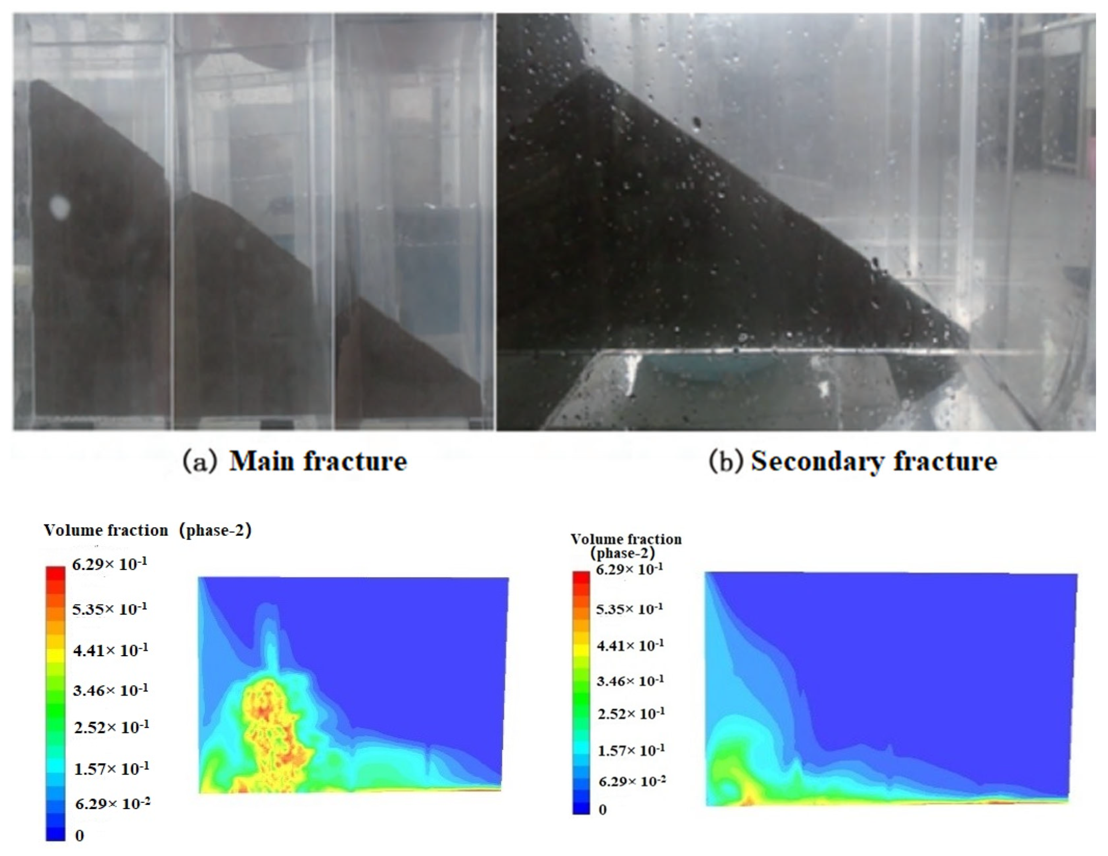
Figure 1. Numerical simulation of sand dike morphology within the primary and secondary fractures.
Energies 16 04421 g001
Figure 2. Height distribution of experimental sand dike (left) and comparison of numerical simulation sand dike height (right).
Energies 16 04421 g002
Figure 3. The modeling schematic of the wellbore.
Energies 16 04421 g003
Figure 4. Transition diagram of sand concentration distribution in cross-section in the wellbore.
Energies 16 04421 g004
Figure 5. Distribution of mass flow rate of mixed-phase in each perforating cluster with 5 mPa·s fracturing fluid flowing time of 30 min.
Energies 16 04421 g005
Figure 6. Distribution of mass flow rate of the liquid phase in each perforating cluster with 5 mPa·s fracturing fluid flowing time of 30 min.
Energies 16 04421 g006
Figure 7. Distribution of mass flow rate of solid phase in each perforating cluster with 5 mPa·s fracturing fluid flowing time of 30 min.
Energies 16 04421 g007
Figure 8. Porosity scatter diagram at different distances from the top of the carboniferous reservoir.
Energies 16 04421 g008
Figure 9. Thin section of carboniferous reservoir core in the target block.
Energies 16 04421 g009
Figure 10. Schematic diagram of the wellbore-tertiary fracture model.
Energies 16 04421 g010
Figure 11. Distribution of proppant within each cluster of primary, secondary and tertiary fractures.
Energies 16 04421 g011
Figure 12. The cumulative flow rate of each cluster proppant.
Energies 16 04421 g012
Figure 13. Sand concentration distribution in fractures with 10 different models.
Energies 16 04421 g013
Figure 14. Proppant distribution (Above) and Flowline distribution of proppant (Below) in the wellbore.
Energies 16 04421 g014
Figure 15. The cumulative flow rate of each cluster proppant at variable displacement.
Energies 16 04421 g015
Figure 16. The cumulative flow rate of the liquid phase in each cluster under variable displacement.
Energies 16 04421 g016
Figure 17. The cumulative flow rate of each cluster proppant at variable viscosity.
Energies 16 04421 g017
Figure 18. Proppant distribution under 1 mPa·s and 5 mPa·s fracturing fluid viscosities. The left figure shows the simulation for 5 min, and the right figure shows the simulation for 10 min.
Energies 16 04421 g018
Figure 19. The cumulative flow rate of each cluster proppant at variable particle size.
Energies 16 04421 g019
Figure 20. The cumulative flow rate of the liquid phase in each cluster under variable particle size.
Energies 16 04421 g020
Figure 21. Proppant distribution under different sand ratios, the left figure shows the simulation for 5 min, and the right figure shows the simulation for 10 min.
Energies 16 04421 g021
Figure 22. Comparison of post-flood production of optimized oil wells and conventional fracturing oil wells.
Energies 16 04421 g022
Table 1. The setting of model and calculation parameters.
ParametersValuesParametersValues
Horizontal well section length65 mDiameter of wellbore118.62 mm
Mass fraction of proppant12%Inlet Displacement12 m3/min
Fracturing fluid density1100 kg/m3Proppant diameter0.8 mm
Fracturing fluid viscosity5 mPa·sProppant density1650 kg/m3
Gravitational acceleration−9.81 m/s2Cluster spacing15 m
Outlet pressure55 MPaWall roughness height32 μm
Perforation diameter10 mmNumber of clusters6
Table 2. The setting of model and calculation parameters.
ParametersValuesParametersValues
Cluster spacing20 mSecondary fracture width4 mm
Half main fracture length90 mTertiary seam width3 mm
Half secondary fracture length20 mFracture angle90°
Half tertiary seam length20 mFracturing fluid viscosity5 mPa·s
Main fracture width6 mmDisplacement12 m3/min
Main fracture height30 mDiameter of wellbore118.62 mm
Table 3. Model modeling scheme table.
Fracture LevelStage/ClustersCluster Spacing/mFractures Angle/°
21/32015
21/32030
21/32045
21/32060
21/32075
21/32090
31/32015/90
31/32030/90
31/32045/90
31/32060/90
Table 4. The setting of model and calculation parameters.
ParametersValuesParametersValues
Cluster spacing25 mOutlet pressure55 MPa
Stage length100 mFracturing fluid viscosity1 mPa·s
Half fracture length75 mDisplacement10 m3/min
Fracture height25 mProppant diameter0.3 mm
Fracture width6 mmProppant mass fraction12%
Table 5. Fracturing design parameter.
WellDisplacement
(m3/min)
Average Sand Ratio
(%)
Total Sand Volume
(m3)
Total Liquid Volume
(m3)
Sand to Liquid Ratio (%)
A112~1411.9121516,40013.5
A212~1412111018,20016.4
A312~1412.3178030,10016.9
Disclaimer/Publisher’s Note: The statements, opinions and data contained in all publications are solely those of the individual author(s) and contributor(s) and not of MDPI and/or the editor(s). MDPI and/or the editor(s) disclaim responsibility for any injury to people or property resulting from any ideas, methods, instructions or products referred to in the content.