Abstract
To optimize the utilization of solar energy in the latent heat thermal energy storage (LHTES) system, this study conducts exergy analysis on a paraffin-solar water shell and tube unit established in the literature to evaluate the effects of different inclination angles, inlet temperatures, original temperatures, and fluid flow rates on the exergy and exergy efficiency. Firstly, the thermodynamic characteristics of the water and the natural convection effects of the paraffin change with different inclination angles. When the inclination angle of the heat storage tank is less than 30°, the maximum exergy inlet rate rises from 0 to 144.6 W in a very short time, but it decreases to 65.7 W for an inclination angle of 60°. When the inclination angle is increased from 0° to 30°, the exergy efficiency rises from 86% to 89.7%, but it decreases from 94% to 89.9% with the inclination angle from 60° to 90°. Secondly, under the condition that the inclination angle of the energy storage unit is 60°, although increasing the inlet temperature of the solar water enhances the exergy inlet and storage and reduces the charging time, it increases the heat transfer temperature difference and the irreversible loss of the system, thus reducing the exergy efficiency. As the inlet water temperature is increased from 83 to 98 °C, the exergy efficiency decreases from 94.7% to 93.6%. Moreover, increasing the original temperature of the LHTES unit not only reduces the exergy inlet and storage rates but also decreases the available work capacity and exergy efficiency. Finally, increasing the inlet water flow rate increases the exergy inlet and storage rates slightly. The exergy efficiency decreases from 95.6% to 93.3% as the unit original temperature is increased from 15 to 30 °C, and it is enhanced from 94% to 94.6% as the inlet flow rate is increased from 0.085 to 0.34 kg/s with the unit inclination angle of 60°. It is found that arranging the shell and tube unit at an inclination angle is useful for improving the LHTES system’s thermal performance, and the exergy analysis conducted aims to reduce available energy dissipation and exergy loss in the thermal storage system. This study provides instructions for solar energy utilization and energy storage.
1. Introduction
Exergy may be used as a measure of meaningful labor in the design, modeling, and performance evaluation of various energy storage systems. Energy analysis only offers data on the amount of energy, but energy quality [1,2,3] is evaluated through the exergy analysis [4,5,6]. Exergy is defined as the maximum available capacity of a unit from a specific beginning state throughout a reversible process when the state is in equilibrium with the environment [7]. Exergy is the most beneficial work that a material or energy flow may produce [8]. Thus, for a given heat source, the exergy efficiency is determined by the available energy and waste heat utilization efficiencies [9]. The primary sources of engineering energy loss may be discovered by examining the exergy and studying the ability of each energy flow to create work [10]. The economic and environmental analyses suggested here can be used with several exergy-based analytical methodologies [11]. The investigation of exergy efficiency as well as economic [12,13,14] and environmental [15] concerns can offer a thorough understanding of how to pick a suitable solution.
The exergy study revealed which system component has the most potential for energy retrofitting [16]. The primary study of a thermal device design must incorporate exergy destruction or entropy generation estimates due to viscous friction and heat transmission [17]. Because of the rise in exergy destruction in the solar energy collector, the system’s exergy efficiency shows a decreasing fluctuation trend [18]. The influence of a turbulent flow condition on energy efficiency and exergy efficiency was studied [19]. When compared to water, the exergy efficiency of the solar energy storage system applying the hybrid nanofluid was improved [20]. Appropriate systematic dimensioning is critical for obtaining maximum exergy efficiency and reducing energy usage [21]. Thermal energy storage (TES) designs for phase change material (PCM) have been developed [22], and systems can recover the needed useful energy during the discharge [23]. The exergy efficiency of the multi-objective working condition was lower than that of the single-objective one, while the energy efficiency was higher [24]. The entropy increases with increasing irreversibility, reducing the system’s ability to be used [25]. Experiments are conducted to investigate the thermophysical characteristics, convective coefficient, entropy amount, and exergy efficiency under turbulent flow [26]. Entropy production refers to the exergy efficiency of a thermal system. Minimum entropy generation is the most important criterion for increasing the system’s exergy efficiency [27]. The effects of Reynolds number [28,29,30], inlet temperature [31], and design parameters [32] on exergy efficiency were investigated. Using the mathematical model [33], the variation laws of exergy loss and transfer coefficient at different testing places of the TES tank throughout the charging process were computed and studied. The model of Ding et al. [34] was used to observe the variation in exergy efficiency as well as the loss of exergy efficiency with different parameters and operating circumstances. According to Si et al. [35], the modeling results demonstrated that the overall thermal efficiency in both energy and exergy generated greater precision. A multi-objective utilization model for thermal systems was developed, using the system’s energy cost minimization and energy efficiency maximization as the optimization functions [36]. In conclusion, sophisticated exergy analysis gives the designer a thorough roadmap for the system’s optimization potential and economic savings [37].
It is crucial to identify the cause of the systematic exergy destruction because of component arrangement and relationships. Exergy analysis, which bases its conclusions on exergy efficiency and thermal performance, is a potent instrument for assessing energy quality. The tube structure played a more significant role in improving the thermal storage performance of the shell and tube LHTES unit [38] compared to the PCM thermal conductivity [39]. The exergy analysis is now studied by adopting the numerical data of the established shell and tube LHTES system [40]. On the one hand, the available work capacity is evaluated in terms of the quality of energy, and, on the other hand, the exergy destruction analysis indicates the entropy generation and the irreversible loss. Figure 1 shows the tube and shell thermal storage unit with four different inclination angles.
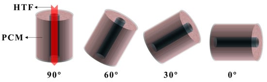
Figure 1.
Configuration of different inclination angles.
In this study, the thermal data of a paraffin-solar water shell and tube unit during the energy storage process with different inclination angles is used to perform exergy and exergy efficiency analyses for the solar energy storage. The sensitivity analysis is conducted by changing operating conditions. A novel way to improve the thermal performance of the LHTES is studied with different inclination angles. It is found that setting the inclination angle of the phase change unit properly is effective in improving the heat convection and thermal performance of the energy storage unit.
2. Mathematical Analysis and Operating Conditions
2.1. Mathematical Model
In this study, the mathematical model used to calculate the exergy rate of the TES unit is shown as follows:
The heat transfer fluid (HTF), whose inlet temperature is higher than the original temperature of the PCM, not only transfers heat to the TES unit but also supplies exergy due to the change in its own thermal state. The exergy inlet can be obtained from the calculation:
where, To is the original environment temperature.
The PCM stores exergy as the thermal state deviates from its original value during the temperature rise and phase change process. The exergy storage of the PCM is as follows:
As the thermal transfer resistance and flowing loss exist, the exergy loss, which indicates the entropy generation of the TES unit, is calculated as follows:
As the potential work capacity is measured by the non-equilibrium degree with the original environment, the exergy efficiency is calculated as follows:
The ratio of the exergy loss to HTF exergy inlet is calculated as the entropy generation number [41]:
The relationship between the exergy efficiency and the entropy generation number is:
The Reynolds number (Re) is defined as the dynamic intensity of the inlet flow. It is calculated as [4]:
The Stefan number (Ste) represents the heat transfer driving force between the HTF and the PCM [4]:
The boundary of the shell is adiabatic, the tube surface, which conducts convective heat transfer between HTF and PCM, is the coupled boundary, and the original conditions for HTF and PCM are as follows:
2.2. Operating Conditions
In order to conduct the exergy analysis of a solar thermal storage system, a shell and tube TES unit with multiple operating conditions established by Peng et al. [40] was applied to evaluate the exergy and exergy efficiency for different inclination angles, inlet conditions, and original conditions. The configuration of different inclination angles studied in the reference and this paper is shown in Figure 1, and the variable and constant conditions are listed in Table 1. The variation pattern of the thermal performance and the mechanism of systematic thermodynamic loss are also discussed. Table 1 also displays the different effect cases, and the inlet intensity shown as Re and the heat transfer driving force shown as Ste are calculated to obtain the different working conditions.

Table 1.
Operating conditions in this study.
3. Results and Discussion
3.1. Effect of Inclination Angle
Figure 2 demonstrates the variation of the exergy inlet rate of the solar water with different inclination angles. When the inclination angle of the shell and tube unit is between 0° and 30°, the exergy inlet trend of the solar water varies similarly, which is different from the inclination angle of 60° and 90°. It shows that the inclination angle varies the heat transfer process of the solar water and the natural convection of the PCM, which influences the transient exergy inlet and thus affects the exergy performance. When the inclination angle of the unit is 0°, the exergy inlet rate rises from 0 to 144.6 W in a very short time, and then it gradually decreases. The maximum exergy inlet rate is 150 W when the inclination angle of the unit is 30°. The exergy inlet rate is only 65.7 W for an inclination angle of 60°, but it decreases slowly. When the inclination angle increases to 90°, the exergy inlet rate is further reduced, and the trend is flatter. The increase in the inclination angle reduces the exergy inlet rate of the solar water and slows down the decreasing trend, which increases the useful energy of the solar water.
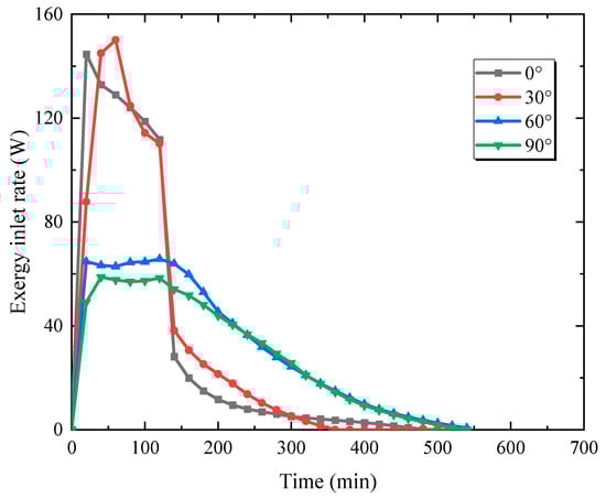
Figure 2.
Exergy inlet rate for different inclination angles.
Figure 3 shows the exergy storage rate for different inclination angles. The exergy storage, which is influenced by the HTF, shows a similar variation trend. When the inclination angle is between 0° and 30°, the exergy storage rate of the PCM reaches its maximum of 55 W at about 120 min, then the exergy storage rate decreases rapidly, which is because the phase change process ends quickly. The exergy storage is finally completed at 480 min with an inclination angle of 0°. Due to the effect of the inlet exergy, the maximum exergy storage rate is only 23.6 W when the inclination angle is 60°, and the maximum exergy storage rate decreases to 21 W when the inclination angle increases to 90°. The time required for the latent heat TES system to complete the radiation increases to 540 min. It can be found that increasing the inclination angle decreases the exergy storage rate of the PCM and extends the exergy storage process.
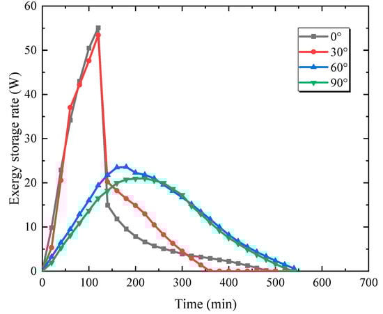
Figure 3.
Exergy storage rate for different inclination angles.
Figure 4 displays the exergy of the system for four inclination angles. The exergy is only 354.3 kJ for the inclination angle of 0°, and 395.1 kJ for the inclination angle of 30°. As the inclination angle increases to 90°, the work capacity of the latent heat storage unit is 369.6 kJ, which is more than the inclination angle of 0° and less compared to the inclination angle of 30°. With an inclination angle of 60°, the exergy is 408.2 kJ, which is the maximum value that can be achieved for four inclination angles. The inclination angle affects the exergy that can be stored by the TES system.
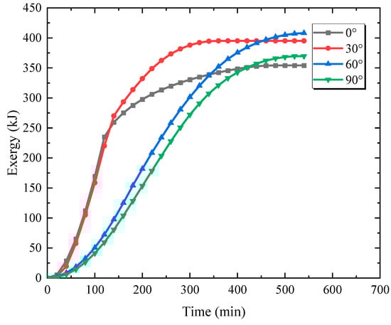
Figure 4.
Exergy for different inclination angles.
Figure 5 shows the exergy efficiency for different inclination angles. For an inclination angle of 0°, the exergy efficiency is 86%, and the time required to complete the variation is 480 min. For an inclination angle of 30°, the exergy efficiency is 89.7%, and it takes 340 min to complete the process. When the inclination angle is 60°, the system obtains the exergy efficiency of 94%, but the time is extended to 540 min. As the inclination angle is 90°, the exergy efficiency of the system decreases to 89.9%, but the change time is also shortened to 520 min. When the inclination angle is less than 60°, increasing the inclination angle of the shell and tube unit increases the exergy efficiency. However, when the inclination angle is further increased, the exergy storage and inlet rate of the system decreases significantly, the required time increases, and the second law efficiency decreases, which affects the performance of the TES system. The exergy analysis of the shell and tube unit with different inclination angles indicates a novel approach for the reasonable arrangement of the solar thermal storage system.
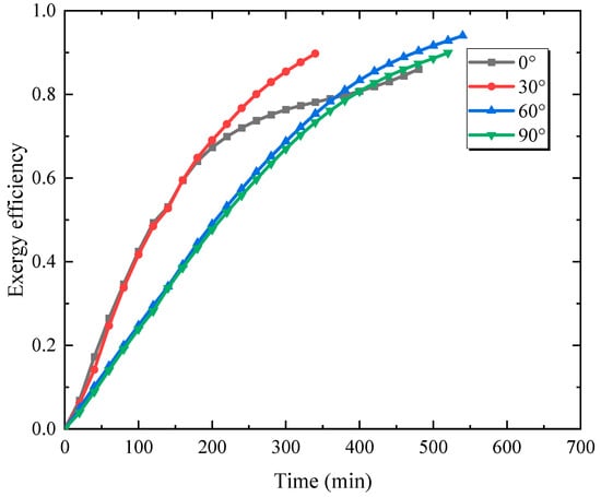
Figure 5.
Exergy efficiency for different inclination angles.
It can be seen from Figure 2 and Figure 3 that HTF obtains solar energy to increase its own temperature and deviate from the original state, thereby being able to produce usable energy. The exergy inlet rate of HTF is much higher than the exergy storage rate of the PCM at the beginning, because HTF has the ability to change the surrounding environment and provide the exergy accumulated by the PCM. As HTF continuously delivers available energy to the PCM, the exergy storage rate of the PCM shows delay and peak attenuation compared to the exergy inlet. However, the thermal state of the PCM continues to approach, and the exergy of the system is continuously produced. In Figure 4, the exergy of the system eventually reaches a certain value. After the charging process is completed, as shown in Figure 5, the exergy efficiency is calculated to analyze the effectiveness of available energy transfer and storage. The changes in exergy and exergy efficiency vary greatly under different inclination angles, but changing the inlet and initial conditions, such as Re and Ste, can also have a positive or negative impact on the thermal performance of the system.
3.2. Effect of Inlet Water Temperature
Figure 6 shows the effects of fluid inlet temperatures on the exergy inlet in the charging process when the inclination angle of the phase change unit is 60°. It is found that increasing the temperature of the solar water significantly enhances the exergy inlet rate and reduces the time required for the HTF to supply the inlet exergy. As is shown in the diagram, the maximum exergy inlet rate is 58.5 W for an inlet temperature of 83 °C, and the time for maintaining the peak value is about 140 min. When the water temperature is 88 °C, the maximum exergy inlet rate of heat transfer fluid increases to 64.7 W, and the time for maintaining the peak value is shortened by 20 min. Increasing the inlet temperature to 93 and 98 °C will increase the maximum exergy inlet rate to 82.5 and 106.6 W, respectively. Increasing the inlet fluid temperature in the system will significantly improve the exergy inlet rate, which accelerates the heat exchange process.
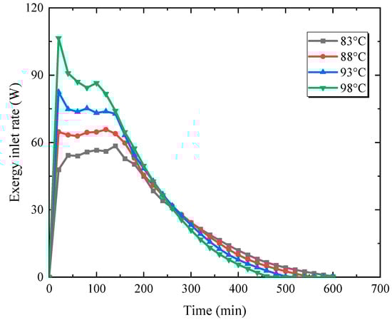
Figure 6.
Exergy inlet rate for different inlet water temperatures.
Figure 7 depicts the effects of different water temperatures on the exergy storage rate of the PCM for an inclination angle of 60°. In general, as the fluid temperature increases, the exergy storage rate increases, and the maximum exergy storage rate is advanced. Increasing the water temperature from 83 to 98 °C will increase the maximum exergy storage rate from 21.1 to 29.7 W. The charging time is reduced from 600 to 420 min, which greatly facilitates the progress. The increase in the inlet temperature significantly enhances the heat transfer drive force, which promotes the convection intensity between the fluid and the paraffin through the tube wall.
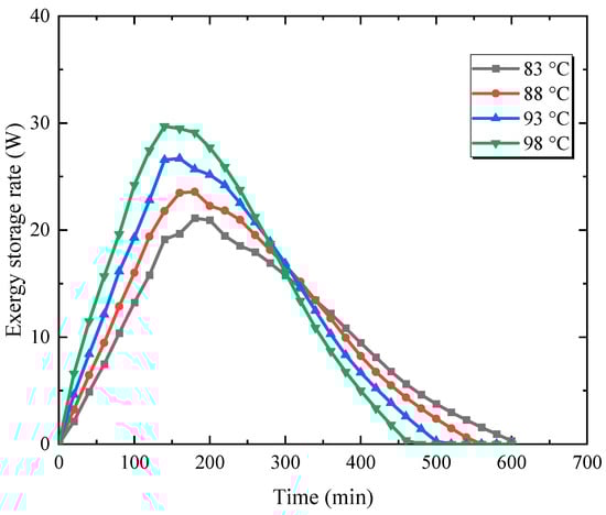
Figure 7.
Exergy storage rate for different inlet water temperatures.
The variation of the exergy for different inlet temperatures is shown in Figure 8. It can be seen that increasing the fluid temperature from 83 to 88 °C increases the exergy from 385.0 to 408.3 kJ. Increasing the fluid temperature from 88 to 93 °C expands the maximum exergy by 20.3 kJ. Raising the fluid temperature by 5 °C further increases the exergy by 23.2 kJ. It can be found that as the fluid temperature increases, the available energy of the system increases, and the variation trend grows. Increasing the fluid temperature causes a significant effect on the energy storage density because it promotes the effective thermal exchange and the PCM final temperature, expanding the deviation from the original state and thus increasing the thermal potential.
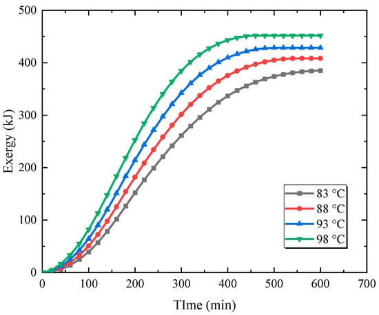
Figure 8.
Exergy for different inlet water temperatures.
Figure 9 demonstrates the exergy efficiency for different inlet temperatures. As shown in the diagram, increasing the fluid temperature reduces the time to complete the thermal storage, thus reducing the variation process of exergy efficiency. For the inlet temperature of 83 °C, the time taken to complete the charging process is 600 min, but the system has the maximum exergy efficiency of 94.7%. Increasing the fluid temperature to 88 °C reduces the time to 540 min, but also reduces the exergy efficiency to 94%. Raising the fluid temperature further reduces the required time. When the fluid temperature is 98 °C, the time required for the system to complete the process is 460 min, and the exergy efficiency is 93.6%. Although increasing the fluid temperature improves the heat transfer process, it will also increase the irreversible energy loss and reduce the exergy efficiency.
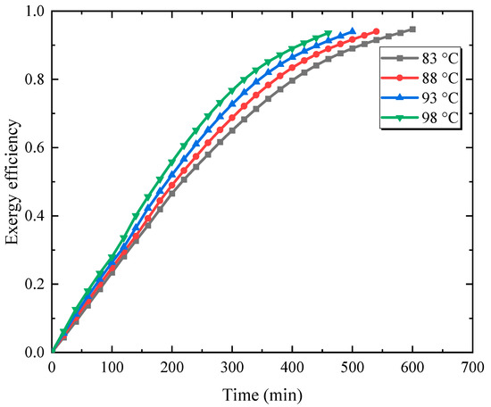
Figure 9.
Exergy efficiency for different inlet water temperatures.
3.3. Effect of Original Temperature
Figure 10 shows the effects of unit original temperatures on the exergy inlet rate when the inclination angle is 60°. The figure shows that increasing the original temperature of the unit reduces the time necessary for the solar water to supply the inlet exergy but also decreases the exergy inlet rate. The maximum exergy inlet rate is 75.7 W when the system’s original temperature is 15 °C. When the system’s original temperature is raised to 20 °C, the exergy inflow rate declines under the same inlet conditions, with a maximum value of 70.1 W. When the temperature is raised to 25 °C, the exergy inflow is reduced even further, and the maximum rate is 65.7 W. When the original temperature is 30 °C, the system has the lowest exergy inlet rate with a maximum value of 55.5 W. Increasing the fluid temperature reduces the heat transfer temperature difference between the solar water and the paraffin, which weakens the thermal transfer intensity and decreases the exergy inlet rate.
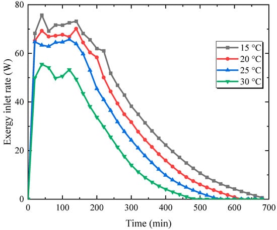
Figure 10.
Exergy inlet rate for different original temperatures.
Figure 11 depicts the variation of the exergy storage rate for different original temperatures. As the original temperature of the unit increases, the exergy storage rate decreases due to the influence of the charging fluid. Although increasing the original temperature reduces the charging time, it decreases both the exergy storage rate and the exergy. As a result, raising the initial temperature by 15 °C decreases the maximum exergy storage rate of the phase change material from 29.9 to 18.0 W.
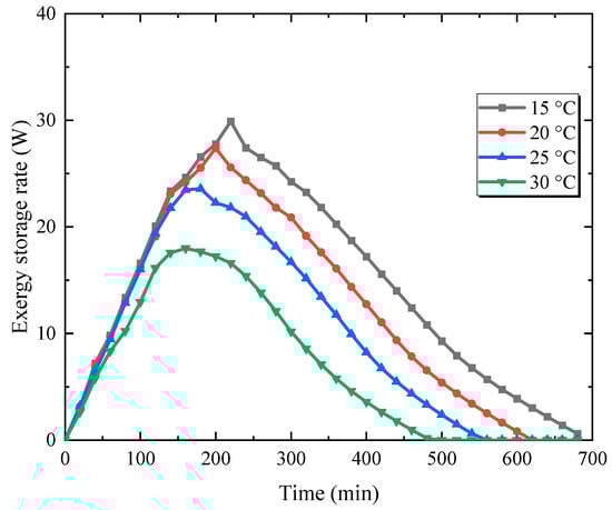
Figure 11.
Exergy storage rate for different original temperatures.
Figure 12 demonstrates the change of the exergy with different original temperatures. From the figure, increasing the original temperature decreases the total available energy gradually. When the PCM temperature is 15 °C, there is a temperature transfer difference between the water and the paraffin, and the system deviates from the original condition after completing the heat storage mostly, so the system maintains the maximum exergy, which is 610.5 kJ. As the PCM temperature is 20 °C, the thermal potential of the unit is weakened, and the exergy is 500 kJ. The original temperature is increased to 30 °C, the exergy is only 275.5 kJ. With the increase in the PCM original temperature, the potential capacity of the system is weakened, the available energy is reduced, and the reduction trend extends.
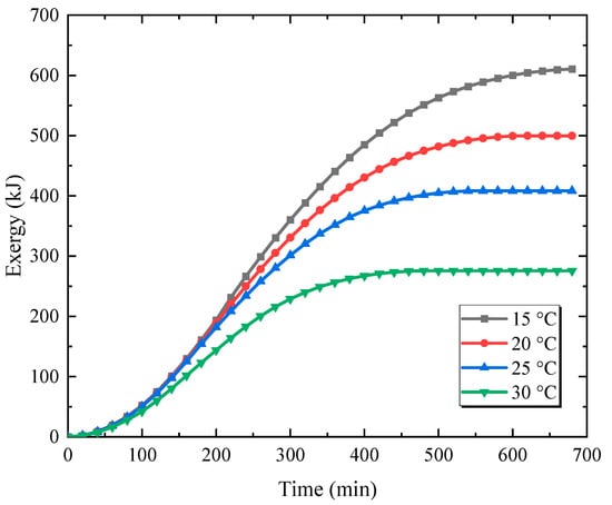
Figure 12.
Exergy for different original temperatures.
Figure 13 reflects the variation of the exergy efficiency with different original conditions. Increasing the original temperature decreases the charging time and decreases the exergy efficiency, which has a negative influence on the thermal performance. The exergy efficiency is 95.6% when the PCM temperature is 15 °C. The system’s exergy efficiency is 94.5% as the original temperature is raised to 20 °C. The exergy efficiency drops to 94% when the original temperature is 25 °C. As the original temperature is 30 °C, the system’s exergy efficiency is 93.3%. Increasing the original temperature of the latent heat unit reduces the useful energy and decreases the heat density of the PCM.

Figure 13.
Exergy efficiency for different original temperatures.
3.4. Effect of Inlet Flow Rate
To investigate the effects of inlet conditions on the thermal performance, the fluid flow rate of the solar water is changed when the inclination angle is 60°. Figure 14 shows the variation of the exergy inlet rate for different inlet flow rates. Although increasing the fluid rate enhances the Reynolds number and thus increases the convective intensity in the tube, increasing the flow rate improves the exergy inlet rate slightly for an inclination angle of 60°. When the fluid flow rate is 0.085 kg/s, the maximum exergy inlet rate is 65.7 W. As the flow rate is 0.170 kg/s, the maximum exergy inlet rate increases to 68.9 W. As the fluid rate rises to 0.255 and 0.340 kg/s, the values are 73.3 and 77 W, respectively.
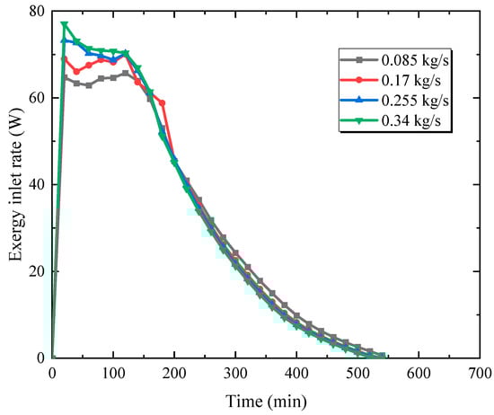
Figure 14.
Exergy inlet rate for different inlet flow rates.
Figure 15 depicts the variation of the exergy storage for different fluid flow rates. Due to the influence of the exergy inlet, the variation of the exergy storage rate of the paraffin is similar. When the fluid flow rate is 0.085 kg/s, the exergy storage rate is 23.6 W. When the fluid flow rate is 0.170 kg/s, the value increases to 27.7 W. As the fluid rate is 0.255 and 0.340 kg/s, the maximum exergy storage rate of the heat exchanger material stabilizes at about 27 W.
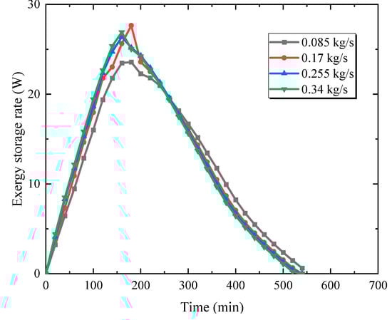
Figure 15.
Exergy storage rate for different inlet flow rates.
Figure 16 shows the effects of fluid flow rates on the exergy of the system. It can be found from the diagram that increasing the fluid rate from 0.085 to 0.340 kg/s has little influence on the work capacity, and the exergy is about 410 kJ.
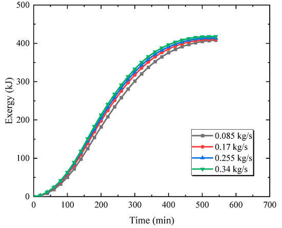
Figure 16.
Exergy for different inlet flow rates.
Figure 17 demonstrates the variation of the exergy efficiency with different fluid flow rates. As can be seen, enhancing the fluid rate of the solar water improves the exergy efficiency, and the exergy efficiency is enhanced from 94% to 94.6%. When the inclination angle is 60°, the effect of gravity on the heat exchange process is prominent, while changing the fluid flow rate affects the exergy slightly.
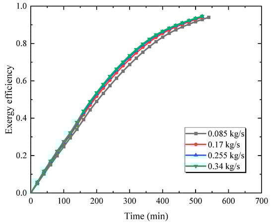
Figure 17.
Exergy efficiency for different inlet flow rates.
3.5. Future Work
Through the exergy analysis of the low-temperature paraffin-solar water unit, it was found that the inclination angle plays a prominent role in optimizing the thermal performance. Therefore, in future works, a complete experimental platform and computational model will be established to conduct in depth research on medium and low temperature thermal storage systems with different inclination angles. The optimal inclination angle of the phase change unit will be found and the thermal performance during the charging and discharging cycles will be evaluated.
4. Conclusions
In this study, the mathematic analysis of the shell and tube unit with different inclination angles in a TES system established in the literature is conducted to evaluate the exergy performance.
The effects of variable inclination angles, inlet temperatures, original temperatures, and inlet fluid rates on the exergy rate and exergy efficiency are evaluated. As a result, there is an effective way to optimize the thermal efficiency of the solar energy system with different inclination angles, and the main conclusions are shown below.
The inclination angle affects the inlet exergy of the fluid and the exergy storage of the PCM due to the effects of energy transfer and natural convection. When the inclination angle is greater than 0° and less than 60°, increasing the inclination angle improves the exergy performance. However, when the inclination angle is greater than 60° but less than 90°, increasing the inclination angle reduces the exergy efficiency.
As the inclination angle of the heat storage tank is 60°, increasing the inlet temperature of the solar water improves the exergy rate and reduces the time required for the exergy storage. The heat transfer driving force, which is shown as the Stefan number, is promoted accordingly. However, it increases the heat transfer temperature difference and the irreversible energy loss, so that the exergy efficiency is reduced. Moreover, increasing the original temperature of the tank not only reduces the tube temperature difference between the fluid and the paraffin but also decreases the exergy inlet and storage rates. As a result, it decreases the work capacity and exergy efficiency. Raising the water rate enhances the exergy inlet and storage rates of the system slightly, and the improvement in the exergy performance is minimal.
Utilizing the inclination angle of the phase change unit is a novel way to improve the heat convection and thermal performance of the energy storage system. The exergy analysis of the paraffin-solar water shell and tube unit in the latent heat TES system indicates that the systematic exergy efficiency is related to the working conditions, inlet and original conditions, geometric features, and material parameters. Different operating processes have either positive or negative effects on the thermal efficiency. Setting the working conditions properly can not only achieve energy savings and cost reduction but also optimize the thermal performance and the operating efficiency.
Author Contributions
Conceptualization, Q.M.; Methodology, H.W.; Investigation, L.P.; Writing—review & editing, W.C. All authors have read and agreed to the published version of the manuscript.
Funding
This work was supported by the National Natural Science Foundation of China (No. 51876147).
Conflicts of Interest
The authors declare no conflict of interest.
Abbreviations
| PCM | Phase change material |
| HTF | Heat transfer fluid |
| TES | Thermal energy storage |
| cp | Specific heat capacity (J/kg·K) |
| Mass flow rate (kg/s) | |
| uf | HTF flow rate (m/s) |
| vf | HTF kinematic viscosity (m2/s) |
| Ex | Exergy (J) |
| Q | Energy (J) |
| T | Temperature (°C) |
| To | Original environment temperature (°C) |
| Hm | Latent enthalpy (J/kg) |
| Ns | Entropy generation number |
| t | Time (min) |
| d | Tube diameter (m) |
| ψ | Exergy efficiency |
| in | Inlet |
| sto | Storage |
| loss | Loss |
| f | HTF |
| p | PCM |
| inlet | Inlet |
| outlet | Outlet |
References
- Li, B.; Hong, W.; Li, H.; Lan, J.; Zi, J. Optimized energy distribution management in the nanofluid-assisted photovoltaic/thermal system via exergy efficiency analysis. Energy 2022, 242, 123018. [Google Scholar] [CrossRef]
- Ural, T.; Karaca Dolgun, G.; Güler, O.V.; Keçebaş, A. Performance analysis of a textile based solar assisted air source heat pump with the energy and exergy methodology. Sustain. Energy Technol. Assess. 2021, 47, 101534. [Google Scholar] [CrossRef]
- Wang, Y.; Huang, F.; Tao, S.; Ma, Y.; Ma, Y.; Liu, L.; Dong, F. Multi-objective planning of regional integrated energy system aiming at exergy efficiency and economy. Appl. Energy 2022, 306, 118120. [Google Scholar] [CrossRef]
- Mao, Q.; Cao, W. Effect of variable capsule size on energy storage performances in a high-temperature three-layered packed bed system. Energy 2023, 273, 127166. [Google Scholar] [CrossRef]
- Sharma, S.; Kumar Das, R.; Kulkarni, K. Sustainability analysis of solar air heater roughned with baffles based on exergy efficiency. Mater. Today Proc. 2022, 69, 75–81. [Google Scholar] [CrossRef]
- Li, S.; Gu, W.; Liu, X.; Zhou, Y.; Chen, Z.; Zhang, X.; Ma, T. Pavement integrated photovoltaic thermal (PIPVT) system: A temporal and spatial analysis of energy and exergy performance. J. Clean. Prod. 2022, 340, 130782. [Google Scholar] [CrossRef]
- Abdalla, A.N.; Shahsavar, A. An experimental comparative assessment of the energy and exergy efficacy of a ternary nanofluid-based photovoltaic/thermal system equipped with a sheet-and-serpentine tube collector. J. Clean. Prod. 2023, 395, 136460. [Google Scholar] [CrossRef]
- Abdalla, A.N.; Shahsavar, A. Numerical investigation of the effect of rotary propeller type turbulator on the energy and exergy efficiencies of a concentrating photovoltaic/thermal hybrid collector. J. Clean. Prod. 2023, 393, 136225. [Google Scholar] [CrossRef]
- Braimakis, K.; Karellas, S. Exergy efficiency potential of dual-phase expansion trilateral and partial evaporation ORC with zeotropic mixtures. Energy 2023, 262, 125475. [Google Scholar] [CrossRef]
- Wang, Y.; He, G.; Huang, H.; Guo, X.; Xing, K.; Liu, S.; Tu, Z.; Xia, Q. Thermodynamic and exergy analysis of high compression ratio coupled with late intake valve closing to improve thermal efficiency of two-stage turbocharged diesel engines. Energy 2023, 268, 126733. [Google Scholar] [CrossRef]
- Ozcan, H.G.; Hepbasli, A.; Abusoglu, A.; Anvari-Moghaddam, A. Energy, exergy, economic, environmental and sustainability (4ES) analyses of a wastewater source heat pump system for district heating applications based on real operational data. Sustain. Energy Technol. Assess. 2023, 56, 103077. [Google Scholar] [CrossRef]
- Nazari, M.; Jafarmadar, S.; Khalilarya, S. Exergy and thermoeconomic analyses of serpentine tube flat-plate solar water heaters coated with CuO nanostructures. Case Stud. Therm. Eng. 2022, 35, 102072. [Google Scholar] [CrossRef]
- Bouadila, S.; Rehman, T.-U.; Baig, M.A.A.; Skouri, S.; Baddadi, S. Energy, Exergy and Economic (3E) analysis of evacuated tube heat pipe solar collector to promote storage energy under North African climate. Sustain. Energy Technol. Assess. 2023, 55, 102959. [Google Scholar] [CrossRef]
- Cao, Y.; Kasaeian, M.; Abbasspoor, H.; Shamoushaki, M.; Ehyaei, M.A.; Abanades, S. Energy, exergy, and economic analyses of a novel biomass-based multigeneration system integrated with multi-effect distillation, electrodialysis, and LNG tank. Desalination 2022, 526, 115550. [Google Scholar] [CrossRef]
- Castiñeiras-Filho, S.L.P.; Pradelle, F. Modeling of microalgal biodiesel production integrated to a sugarcane ethanol plant: Energy and exergy efficiencies and environmental impacts due to trade-offs in the usage of bagasse in the Brazilian context. J. Clean. Prod. 2023, 395, 136461. [Google Scholar] [CrossRef]
- Salek, F.; Eshghi, H.; Zamen, M.; Ahmadi, M.H. Energy and exergy analysis of an atmospheric water generator integrated with the compound parabolic collector with storage tank in various climates. Energy Rep. 2022, 8, 2401–2412. [Google Scholar] [CrossRef]
- Eltaweel, M.; Abdel-Rehim, A.A.; Attia, A.A.A. A comparison between flat-plate and evacuated tube solar collectors in terms of energy and exergy analysis by using nanofluid. Appl. Therm. Eng. 2021, 186, 116516. [Google Scholar] [CrossRef]
- Chen, J.; Zhang, Z.; Zhang, G.; Wang, D. Energy, exergy, economic and environmental analysis of a novel direct-expansion solar-assisted flash tank vapor injection heat pump for water heater. Energy Convers. Manag. 2022, 254, 115239. [Google Scholar] [CrossRef]
- Alnaqi, A.A.; Al-Rashed, A.A.A.A. Impact of vortex generator and two-phase MWCNT-MgO/water hybrid nanofluid on thermo-hydraulic performance and exergy and energy efficiency of a solar collector under Kuwait climatic conditions. Eng. Anal. Bound. Elem. 2023, 151, 175–186. [Google Scholar] [CrossRef]
- Cui, F.; Liu, F.; Tong, Y.; Wang, S.; Guo, W.; Han, T.; Qiu, X. Energy and exergy assessment of evacuated tube solar collector using water, Fe3O4 nanofluid and Fe3O4/MWCNT hybrid nanofluid. Process Saf. Environ. Prot. 2022, 163, 236–243. [Google Scholar] [CrossRef]
- Nikolic, D.; Skerlic, J.; Radulovic, J.; Miskovic, A.; Tamasauskas, R.; Sadauskienė, J. Exergy efficiency optimization of photovoltaic and solar collectors’ area in buildings with different heating systems. Renew. Energy 2022, 189, 1063–1073. [Google Scholar] [CrossRef]
- Mohammadpour, J.; Lee, A.; Timchenko, V.; Taylor, R. Nano-Enhanced Phase Change Materials for Thermal Energy Storage: A Bibliometric Analysis. Energies 2022, 15, 3426. [Google Scholar] [CrossRef]
- Riahi, S.; Liu, M.; Jacob, R.; Belusko, M.; Bruno, F. Assessment of exergy delivery of thermal energy storage systems for CSP plants: Cascade PCMs, graphite-PCMs and two-tank sensible heat storage systems. Sustain. Energy Technol. Assess. 2020, 42, 100823. [Google Scholar] [CrossRef]
- Cao, H.; Mao, Y.; Wang, W.; Gao, Y.; Zhang, M.; Zhao, X.; Sun, J.; Song, Z. Thermal-exergy efficiency trade-off optimization of pressure retarded membrane distillation based on TOPSIS model. Desalination 2022, 523, 115446. [Google Scholar] [CrossRef]
- Mouli, K.V.V.C.; Sundar, L.S.; Alklaibi, A.M.; Said, Z.; Sharma, K.V.; Punnaiah, V.; Sousa, A.C.M. Exergy efficiency and entropy analysis of MWCNT/Water nanofluid in a thermosyphon flat plate collector. Sustain. Energy Technol. Assess. 2023, 55, 102911. [Google Scholar] [CrossRef]
- Syam Sundar, L. Experimental study on the thermophysical properties, heat transfer, thermal entropy generation and exergy efficiency of turbulent flow of ZrO2-water nanofluids. Alex. Eng. J 2023, 65, 867–885. [Google Scholar] [CrossRef]
- Sundar, L.S.; Shaik, F. Laminar convective heat transfer, entropy generation, and exergy efficiency studies on ethylene glycol based nanofluid containing nanodiamond nanoparticles. Diam. Relat. Mater. 2023, 131, 109599. [Google Scholar] [CrossRef]
- Syam Sundar, L. Heat transfer, friction factor and exergy efficiency analysis of nanodiamond-Fe3O4/water hybrid nanofluids in a tube with twisted tape inserts. Ain Shams Eng. J. 2022, 14, 102068. [Google Scholar] [CrossRef]
- Sundar, L.S.; Shaik, F. Heat transfer and exergy efficiency analysis of 60% water and 40% ethylene glycol mixture diamond nanofluids flow through a shell and helical coil heat exchanger. Int. J. Therm. Sci. 2023, 184, 107901. [Google Scholar] [CrossRef]
- Khetib, Y.; Sait, H.; Habeebullah, B.; Hussain, A. Numerical study of the effect of curved turbulators on the exergy efficiency of solar collector containing two-phase hybrid nanofluid. Sustain. Energy Technol. Assess. 2021, 47, 101436. [Google Scholar] [CrossRef]
- Vahidinia, F.; Khorasanizadeh, H.; Aghaei, A. Energy, exergy, economic and environmental evaluations of a finned absorber tube parabolic trough collector utilizing hybrid and mono nanofluids and comparison. Renew. Energy 2023, 205, 185–199. [Google Scholar] [CrossRef]
- Carmona, M.; Rincón, A.; Gulfo, L. Energy and exergy model with parametric study of a hot water storage tank with PCM for domestic applications and experimental validation for multiple operational scenarios. Energy Convers. Manag. 2020, 222, 113189. [Google Scholar] [CrossRef]
- Ji, S.; Cheng, Q.; Sun, W.; Qi, Y.; Wang, S. Study on optimal operation conditions in the heating process of a crude oil single-disk floating roof tank: Insights from exergy transfer analysis method. Energy Rep. 2023, 9, 3131–3147. [Google Scholar] [CrossRef]
- Ding, S.; Guo, B.; Hu, S.; Gu, J.; Yang, F.; Li, Y.; Dang, J.; Liu, B.; Ma, J. Analysis of the effect of characteristic parameters and operating conditions on exergy efficiency of alkaline water electrolyzer. J. Power Sources 2022, 537, 231532. [Google Scholar] [CrossRef]
- Si, Y.; Brumercik, F.; Yang, C.; Glowacz, A.; Ma, Z.; Siarry, P.; Sulowicz, M.; Gupta, M.K.; Li, Z. Prediction and evaluation of energy and exergy efficiencies of a nanofluid-based photovoltaic-thermal system with a needle finned serpentine channel using random forest machine learning approach. Eng. Anal. Bound. Elem. 2023, 151, 328–343. [Google Scholar] [CrossRef]
- Hu, Z.; He, D.; Zhao, H. Multi-objective optimization of energy distribution in steel enterprises considering both exergy efficiency and energy cost. Energy 2023, 263, 125623. [Google Scholar] [CrossRef]
- Hançer Güleryüz, E.; Özen, D.N. Advanced exergy and exergo-economic analyses of an advanced adiabatic compressed air energy storage system. J. Energy Storage 2022, 55, 105845. [Google Scholar] [CrossRef]
- Mao, Q.; Zhang, Y. Study on the thermal storage performance of a new cascade structure phase change thermal storage tank. J. Energy Storage 2022, 56, 106155. [Google Scholar] [CrossRef]
- Wu, Y.; Li, D.; Jiang, W.; Zhu, S.; Zhao, X.; Arıcı, M.; Tunçbilek, E. Energy storage and exergy efficiency analysis of a shell and tube latent thermal energy storage unit with non-uniform length and distributed fins. Sustain. Energy Technol. Assess. 2022, 53, 102362. [Google Scholar] [CrossRef]
- Peng, L.; Wu, H.; Mao, Q. Numerical and experimental study on the performance of a thermal energy storage in a solar building. J. Energy Storage 2023, 61, 106745. [Google Scholar] [CrossRef]
- Pahamli, Y.; Hosseini, M.J.; Ardahaie, S.S.; Ranjbar, A.A. Improvement of a phase change heat storage system by Blossom-Shaped Fins: Energy analysis. Renew. Energy 2022, 182, 192–215. [Google Scholar] [CrossRef]
Disclaimer/Publisher’s Note: The statements, opinions and data contained in all publications are solely those of the individual author(s) and contributor(s) and not of MDPI and/or the editor(s). MDPI and/or the editor(s) disclaim responsibility for any injury to people or property resulting from any ideas, methods, instructions or products referred to in the content. |
© 2023 by the authors. Licensee MDPI, Basel, Switzerland. This article is an open access article distributed under the terms and conditions of the Creative Commons Attribution (CC BY) license (https://creativecommons.org/licenses/by/4.0/).