Abstract
For national energy capacity improvement and CO2 emission reductions, Mongolia has focused its attention on grid-connected residential PV systems. Due to the feed-in tariff (FIT), the aggregated residential PV systems are expected to increase with the PV penetration level. Currently, there is no power injection limitation in Mongolia. A new policy for the PV penetration level of residential PV systems needs to be developed. This study analyzed the techno-economic performances of distributed PV-battery systems, considering PV generation, the historical load demand, and the tariff structure. We studied the performances of 40 combinations of PV sizes (2 kW–9 kW) and battery capacities (4.4 kWh, 6.6 kWh, 10 kWh, 12 kWh, and 15 kWh) to find feasible system sizes. The aggregated PV-battery systems in a low-voltage (LV) distribution system located in Ulaanbaatar, Mongolia, are also discussed. The results show that six combinations satisfied the technical and economic requirements. The maximum profit was determined to be an NPV of 1650 USD with a 9-year payback period using combination 3 (6 kW PV and 6.6 kWh battery capacity). Combination 6 (8 kW PV and 15 kWh battery capacity) shows that the energy management strategy for residential houses with battery storage has the potential to increase the installed capacity of PV systems without voltage violence in the LV network. For the distributed PV-battery storage system (BSS), the environmental analysis indicates that CO2 and SO2 emissions were reduced by 3929 t/year and 49 t/year, respectively. The findings obtained from this analysis will be used for power system planning.
1. Introduction
Ulaanbaatar (UB), the capital city of Mongolia, is one of the most air-polluted cities in the world. CO2 emissions have increased due to fossil-based energy sources and stoves with the solid fuels used in the “Ger” district. Meanwhile, the national energy consumption exceeds the national energy generation, mostly in the harsh wintertime; therefore, energy is imported from neighboring countries. The Government of Mongolia launched a policy that enables households and industrial and commercial businesses to install grid-connected renewable energy sources (RESs) to combat these concerns [1]. RESs are crucial alternatives in both the energy and environmental sectors. This is also considered one of the important decisions under the Paris Agreement, which around 175 countries, including Mongolia, signed to decrease greenhouse gases (GHG) [2]. In Mongolia, while utility-scale PV and wind farms make up around 10% of the total national capacity, the distributed grid-connected RES is still in its initial stages. Thus, the authors investigated the potential of a grid-connected residential PV system since the residential area, known as a ger khoroolol, in Ulaanbaatar is the main region that produces CO2 emissions, and it contains the dominant consumers of the utility grid. According to the national statistical report in 2020, there were 317,944 houses and 91,249 gers (traditional Mongolian dwellings) utilizing traditional stoves with solid fuels in UB [3]. It is expected that the level of CO2 emissions will significantly decrease when at least half of the households replace conventional stoves with rooftop PV systems.
PV systems can play a significant role in supporting the grid by providing clean energy, reducing transmission congestion, and contributing to grid stability and reliability. In addition, the feed-in tariff (FIT) scheme, which offers customers the chance to trade their surplus PV energy, has a significant advantage in an increase in households that are interested in PV systems. This scheme might be able to lift a huge financial burden off the customers. In our previous study [4], an economic analysis in a private ger with a PV-battery system demonstrated that the deployment of PV systems has the potential to be profitable.
Despite that, as PV generation sources become more prevalent in the electricity grid, the ability to control when electricity is generated is reduced. Unlike the current system, where power is produced to meet consumer demand, PV sources only generate electricity when there is sunlight. This creates a challenge for the traditional electricity network, which relies on a predictable load and one-way power flow from generators to consumers [5]. Traditional power distribution networks can only accommodate a certain amount of photovoltaic (PV) generation, and when there is a substantial surplus of PV generation and low demand for electricity, the voltage in the network may exceed its limits, potentially causing problems [6,7,8,9]. Several approaches to mitigate the technical problems caused by high PV penetration have been reviewed in [10,11]. Demand-side management (DSM) and BSSs are taken into account as the most promising solutions. Electricity utilities adopt DSM as a technique to regulate demand by motivating consumers to adjust their electricity consumption level and pattern. Gobind Pillai et al. [12] showed that even though DSM could be a preferred method due to its potential for deployment through comprehensive demand response initiatives in countries, technically it is not effective in avoiding PV energy curtailment because of a weaker low-voltage network with higher solar resources. Distribution system operation (DSO) ensures the stability of the grid and power quality at a low voltage level. The injection of power into the grid or the installed power of PV generators is restricted to mitigate the impact of abrupt power fluctuation. Owners are not authorized to inject power into the grid beyond a specific percentage of the installed power [13]. This might result in decreases in owners’ benefits and advantages. To cope with this problem, some researchers proposed a centralized storage system to increase PV penetration in low-voltage networks [14]. The total net present value (NPV) has increased with increases in the PV penetration level [15]. A shared energy storage system (ESS) with an operation strategy has been proposed to reduce curtailment and maximize profit [16]. The result indicated that the algorithm utilizes the power-sensitivity-based allocation ratio to calculate the profit sharing among PV power producers. Shared energy storage systems (ESSs) can be implemented by sharing infrastructure costs, which can enhance regional profits by maximizing arbitrage profit through charging and discharging operations.
However, in accordance with the policy from the Mongolian Government, households who install a PV system must install a battery system. This is not only to increase the self-consumption of the household PV system but also to decrease the reverse power flow fed into the LV network. The operation strategies for household PV-battery systems have been discussed based on the electricity tariffs [17,18,19] to increase self-consumption. These operational strategies can be chosen and applied in accordance with the economic and technical conditions. Some researchers have revealed their extensive studies on increasing self-consumption rates utilizing battery energy storage systems [20,21]. The deployment of electric vehicles has been introduced to extend the self-usage in residential PV systems [22]. The EV storage of household PV generation shows the potential to improve both self-consumption and self-sufficiency.
This research work builds upon a previous study that suggested a simple operation strategy for a grid-connected PV-battery system to be utilized in Mongolian gers and houses. This paper presents a technical and economic effectiveness investigation of PV and battery systems for Mongolian households, with a focus on self-consumption and self-sufficiency based on the payback period and NPV. The paper also analyzes the impact of distributed PV-BSSs on a low-voltage network consisting of 40 houses located in UB, Mongolia. Mongolia currently has no limitations on power injection from residential PV systems, but there may be a need for limitations in weak low-voltage networks to ensure grid stability and reliability. The findings will contribute to improving power system planning and mitigating the Mongolian ger khoroolol’s dependency on solid fuels, thereby reducing air pollution. The following sections provide a detailed account of the research work. Section 2 presents the method for investigating the performances of PV systems with BSSs in Mongolian households, which includes historical electrical data and low-voltage network parameters. Section 3 outlines the simulation results and subsequent discussions. Finally, Section 4 presents the conclusions of the study.
2. Materials and Methods
2.1. Data Collection
Mongolia is one of the coldest countries in the world. The ambient temperature in UB is shown in Figure 1a. In the winter, the temperature reaches as low as −30 degrees Celsius [23]. Despite cold winters, UB has abundant sun irradiation, which reaches 1 kW/m2 during the warm season. The measured solar radiation is illustrated in Figure 1b. A PV system generates electricity during the middle of the day (7 a.m.–7 p.m.) each month. The peak monthly consumption of a house occurs in winter since electrical consumers tend to deploy electric heaters or other appliances, whereas the lowest consumption occurs in summer. Considering the daily curve for a private house in Figure 1c, the peak electricity loads occur from 7 to 12 a.m. and from 5 to 9 p.m. This is a common profile in Mongolian households.

Figure 1.
Simulated historical data. (a) Ambient temperature in Ulaanbaatar. (b) The daily solar irradiance during the four seasons. (c) A household’s seasonal daily electricity profile.
PV power generation depends on solar radiation and the temperature, and the power output from a PV system () is calculated using Equation (1):
where is the maximum power in , is the nominal solar irradiance (), is the measured solar irradiance (), and is the temperature coefficient.
2.2. The Grid-Connected Residential PV-Battery System
The configuration of a grid-connected residential PV-battery system includes a direct current (DC)-coupled PV and battery system, as shown in Figure 2. The DC-coupled PV and battery system uses a single inverter to convert the direct DC electricity generated by the PV arrays and the electricity stored in the BSS into alternating current (AC) electricity that can be used by the household and fed back into the grid. In this system, the DC electricity from the PV arrays and the BSS are combined and fed into the inverter, which converts the DC electricity into AC electricity. The AC electricity is then used to power the home’s appliances or fed back into the grid. This configuration allows for more efficient use of the energy stored in the BSS, as the BSS is directly connected to the inverter and does not need to go through a separate DC/AC conversion process. Additionally, it allows for greater control over the charging and discharging of the BSS, which can help the system’s performance and increase its lifespan.
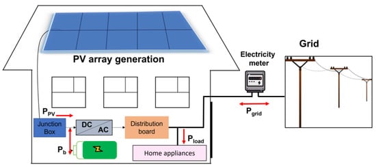
Figure 2.
A general layout of a rooftop PV battery system for a private house.
The energy management strategy is shown in Figure 3.
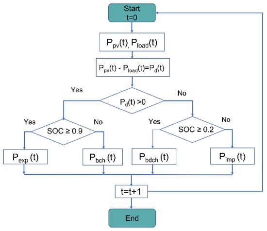
Figure 3.
Home energy management strategy [4].
The basic working principle is that when PV power output exceeds demand, the battery storage is charged by the PV energy. Then, excess energy is sold to the grid. When the correlation between PV generation and demand is too low, the battery storage discharges to cover the load demand. If neither the PV nor the battery storage can fulfill the load, power is purchased from the utility grid to cover the demand.
Power balance, defined as Equation (2), forms the electricity demand of the consumer at each time step.
where is the grid power. It corresponds to the import power (Pimp) when the power value is positive and the export power (Pexp) when the power value is negative at time t. Pload is the load power, PPV is the PV output power, and Pb is the battery charging (Pbch) and discharging (Pbdch) power.
The accumulated energy of the battery is defined as the state of charge (SOC), and the SOC is calculated using Equation (3):
where is the nominal battery capacity and the SOC is represented as a percentage.
The battery storage system is charged between 9 a.m. and 5 p.m. based on the state of charging and discharging constraint, as described in Equation (4), to avoid the deep charging of the battery. The minimum state of charge () is equal to 20%, and the maximum state of charge () is set to 90% of the battery’s nominal capacity.
2.3. Simulation Method in the Low-Voltage (LV) Network
In this research work, the households were assumed to use a similar home energy management strategy for their PV-battery systems. One of the advantages of a battery system is the smoothing of PV power output by storing excess energy, which can be directed to the grid, thereby releasing the LV grid stress. Figure 4 shows the power system line that represents the community including 40 houses. The network was assumed to be a balanced three-phase network, and the PV-battery systems were also assumed to be evenly installed in four feeders. The 10 initial houses were positioned at a distance of 50 m from the 10/0.4 kV transformer, and subsequent allocations were made for each of the buses downstream, which also had a separation of 50 m. The household demand load data and the network parameters were obtained from the domestic distribution company. The LV network normally operates at 400 V (1.0 p.u). The statutory voltage limits are 360 V (0.9 p.u) and 410 V (1.1 p.u).

Figure 4.
A single-line diagram for the community system.
The voltage at the point of common coupling (PCC) in active and reactive power flow through the line is generally calculated using Equation (5):
A three-phase DC-sourced inverter (PVB1-PVB-4) was used to analyze the impact of excess energy (PV penetration) on the power system. Figure 5 shows a diagram of a DC-sourced three-phase inverter connected to the grid and its control system. The PQ control method utilizes the inverter to provide the necessary real and reactive power according to predetermined set-points. This control system includes loops for current and power, with the current loop providing a quick response to any disruptions in input voltage, inductance parameters, and converter dead time, among other things. A phase-locked loop (PLL) is employed to synchronize the inverter with the grid.
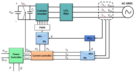
Figure 5.
Block diagram of DC-sourced three-phase grid-connected inverter [24,25].
The PV source constantly supplies real and reactive power to the grid using PQ control, which is based on the dq reference frame. This reference frame is used to define the components of the d-axis and q-axis AC currents. The primary aim of PQ control in an inverter connected to the grid is to guarantee that the inverter generates the reference real and reactive power in accordance with its designated references. The active (P) and reactive powers (Q) can be expressed as follows:
where and are the d-axis and q-axis of the grid-side voltage, respectively, and and are the d-axis and q-axis of the grid-side current, respectively.
A low-voltage grid transformer with the realistic parameters of a suburban area in UB was selected. The parameters of the LV model are given in Table 1.

Table 1.
Parameters of the LV model.
To investigate the voltage fluctuation of the LV system, 40 aggregated residential load profiles were simulated with 8 installed PV sizes and 5 installed battery capacities, as given in Table 2. A three-phase power flow simulation was performed using PSCAD. Typically, the electrical voltage of an LV network system depends on the load characteristics, the location, and the installed PV capacity.

Table 2.
The household PV capacity and the installed PV capacity in the public grid.
The limitation of this paper is that the PV penetration level and the PV location were not investigated. In [26], voltage rise could be controlled by the line impedance between the PV location and the transformer, and the mitigation approach was studied by moving the transformer’s location.
3. Results and Discussion
3.1. Technical Analysis
Self-consumption and self-sufficiency are the main energy indicators that define the correlation between PV generation and load demand.
Self-consumption (SC) refers to a rate that defines the energy that is locally consumed from the PV generation with respect to the total PV generation. The ratio can be calculated using Equation (8):
where t is the time duration in which the self-consumption rate is calculated hourly, daily, monthly, or yearly. is the amount of electricity consumed locally. is the total PV generation.
Self-sufficiency (SS), given in Equation (9), refers to the ratio of the amount of locally consumed electricity () to the total consumption ().
In other ways, self-consumption means that the total PV generation is equal to the sum of the energy consumed locally and the excess power exported into the grid, whereas self-sufficiency means that the total load demand is equal to the sum of the power consumed locally from the PV generation and power purchased from the grid.
Figure 6 illustrates the self-consumption and self-sufficiency ratios as a function of PV size (1 kW–9 kW) without battery storage using the annual household demand and the PV generation profile. The self-consumption ratio decreased, whereas the self-sufficiency rate increased and then remained stable. It was observed that the correlation between the PV generation and load demand kept declining as the PV size increased, thereby sending a significant amount of the excess energy to the grid. From the perspective of the consumers, the installation of a PV system alone became more profitable due to the revenue from selling excess energy, thereby lowering the payback period.
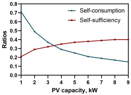
Figure 6.
Impact of a PV system without battery storage.
However, a large amount of excess energy flowing from the distributed PV systems had negative impacts on the LV network. This reverse power flow led to a voltage rise in the public grid. Figure 7 shows the voltage fluctuation of the LV network during the connection of distributed PV systems with an installed capacity of 240 kW.
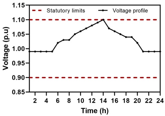
Figure 7.
The voltage magnitude of the LV network with the installed capacity of 240 kW of distributed PV systems.
According to Equation (5), the voltage profile depends on the difference between PV generation and load demand as well as the line impedance. As reverse power flow increases, the voltage at the load end is likely to increase as well. As a result, this can lead to network voltage control equipment cycling, which can have an impact on asset life and maintenance.
By considering the self-consumption ratio of distributed PV systems with battery storage, they are believed to keep the voltage at a normal level. A battery storage system is a tool that balances the PV generation and load demand, thereby increasing the SC ratio. For this purpose, the SC and SS ratios were investigated in 40 combinations (2 kWp–9 kWp PV systems with five battery storage capacities: 4.4 kWh, 6.6 kWh, 10 kWh, 12 kWh, and 15 kWh) over one year in the distribution system. As illustrated in Figure 8, it was observed that the self-consumed energy rose significantly for the PV sizes with the relative battery capacities because the surplus power was stored in battery storage for later use. For the high PV capacity with lower battery capacities, the self-consumed energy decreased because the battery could not store the surplus power from the PV generation, whereas the lower PV capacity with small battery capacities had a better self-consumption ratio.
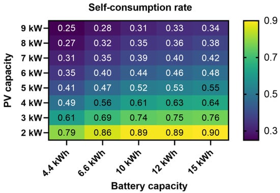
Figure 8.
The self-consumption variables of PV sizes and battery capacities.
The self-sufficiency ratio shown in Figure 9 clearly increased as the battery system increased due to the load being constant. With a high PV size and high battery capacities, the self-sufficiency ratio had stable growth because the consumers purchased less electricity from the grid.
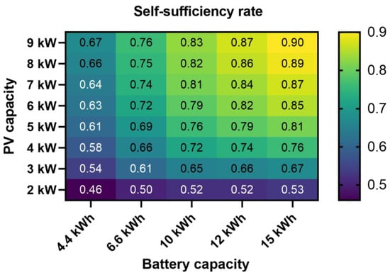
Figure 9.
Self-sufficiency rates for PV sizes and relative battery sizes.
The highest self-consumption and self-sufficiency ratios showed opposite directions. The optimal size of the battery storage system is a crucial element, and it strongly depends on the household load demand and market conditions.
3.2. Economic Analysis
Daily electricity prices were taken into consideration to calculate the economic profits. The electricity tariff is divided into three types of tariff structures in the current electricity market of Mongolia. In this study, the cost of the electricity from the grid was 0.045 USD/kWh, and the feed-in tariff was assumed to be constant, around 0.043 USD/kWh, corresponding to the agreement between the consumers and the grid. Equation (10) refers to the NPV of the project, which determines the project profit that has zero difference between total investment and cash flow.
where is the cash inflow over time, is the investment cost, is the discount rate, and is the time duration.
The cash inflow included the electricity bill savings and the revenue from selling electricity. The investment cost included the PV system, battery, and converter expenditure. The battery system’s lifetime was 10 years, and the project time was assumed to be 10 years without operation and maintenance costs. A discount rate (i) in the range of 4–6% is commonly assumed. Thus, the discount rate (i) was assumed to be 6% in this study. The PV system assessment was based on the payback period and the profit. The cost assumptions of the model are given in Table 3.

Table 3.
Input data for the economic model.
A battery system can improve self-consumption and self-sufficiency, but the investment cost of the battery storage system increases the payback period because the selling revenue is lower than the battery storage expenditure. On the other hand, increasing self-consumption and self-sufficiency make the electricity bill for the power purchased from the grid decrease. This is the merit of this dispatch operation.
The payback periods of the 40 simulated combinations are illustrated in Figure 10. High PV sizes with lower battery capacities had lower payback periods of 6–10 years, whereas the middle PV size with a relative battery capacity corresponding to a better SC ratio had a medium payback period of around 9–19 years. In addition, the longest payback periods of around 23–40 years showed the result of the battery not being fully charged by the PV system because the PV generation was lower than the battery consumption, so these combinations did not provide good economic or technical results.
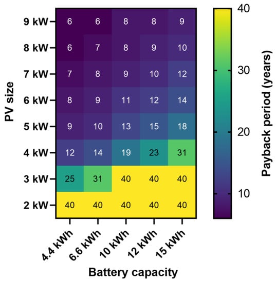
Figure 10.
Payback periods of the PV-battery systems.
As a result of the simulation, some constraints were given to select the feasible size region. From the perspective of the grid, the SC ratio was assumed to be higher than 0.38, and the SS ratio was higher than 0.60. In contrast, the payback period was assumed to be lower than 10 years from the viewpoint of the customer. The feasible sizes of the PV systems with battery storage systems are the six combinations presented in Table 4. Comparing these combinations, it was observed that combination 3 had the maximum profit (1631 USD) and a lower payback period (9 years), whereas combination 6 had the lowest profit (188 USD), but it had the maximum installed capacity of the PV systems of 320 kW.

Table 4.
The optimal size combinations in the LV grid.
After the combination selections, the effect of the aggregated PV and battery systems with the power flow management strategy on the distribution grid was considered through the feeder. Figure 11 shows the LV network voltage with an installed PV capacity of 240 kW and a battery capacity of 6.6 kWh. The battery storage was charged when the PV generation was high, and the result shows that the battery storage system with the energy management operation strategy for the household PV system mitigated the voltage magnitude compared to the PV system without battery storage.
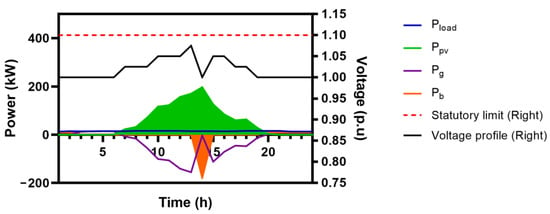
Figure 11.
Voltage magnitude with the distributed PV systems with battery storage.
3.3. Environmental Analysis
The combustion of fossil fuels such as coal, oil, and natural gas produces harmful carbon dioxide (CO2) and sulfur dioxide (SO2) emissions. Mitigating the emission level in Mongolia is becoming urgent. A PV system is considered a zero-emission electricity generator. A significant number of PV installations may noticeably reduce harmful emissions. Obtaining emission parameters for the production of electricity is crucial for evaluating GHG reductions, as shown in Table 5.

Table 5.
Emission factors for electricity generation [27].
Annual PV electricity generation was considered to evaluate the CO2 and SO2 reductions. Figure 12 shows that the trend of emission reductions is likely to increase as PV installation increases. For the distributed PV systems, the annual maximum CO2 and SO2 emission reductions were 3929 t/year and 49 t/year, respectively.
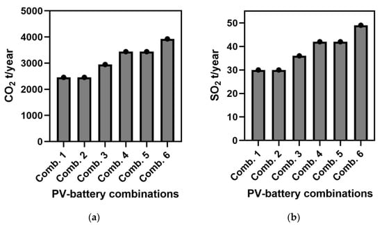
Figure 12.
The expected emission reductions as a function of PV-battery capacity combinations. (a) CO2 emissions. (b) SO2 emissions.
4. Conclusions
Mongolia is focused on implementing grid-connected residential PV systems to improve the national energy capacity and reduce CO2 emissions. The FIT has incentivized the deployment of PV systems, and there is currently no power limit. A new policy is needed to regulate the PV penetration level. This study investigated the techno-economic performances of residential PV-battery systems and the impact of PV penetration on the LV network in Ulaanbaatar, Mongolia. Based on 40 PV and battery size combinations, six combinations were obtained that met the technical and economic performance requirements. From the perspective of the customer, the results show that combination 3 provided the maximum profit. From the grid side, it was observed that combination 6 confirmed the increase in PV penetration in the LV network without voltage violence. Moreover, the residential PV-battery systems reduced CO2 and SO2 emissions by 3929 t/year and 49 t/year, respectively. A future work will design a new policy for the Mongolian power system for the PV penetration level of residential PV systems.
Author Contributions
Conceptualization, N.U.; methodology, B.E.; formal analysis, B.E.; investigation, N.U.; resources, D.B.; data curation, B.E. and D.B.; writing—original draft preparation, B.E.; writing—review and editing, N.U. and B.E.; supervision, N.U. and S.B. All authors have read and agreed to the published version of the manuscript.
Funding
This research received no external funding.
Data Availability Statement
Not applicable.
Acknowledgments
This research was supported by the “Higher Engineering Education Development” project Research on Innovation of Electrical Distribution and Transmission (J222C15).
Conflicts of Interest
The authors declare no conflict of interest.
References
- The Integrated Legal Information System. Available online: https://legalinfo.mn/mn/detail?lawId=211259&showType=1/ (accessed on 30 April 2023).
- United Nations. Sustainable Development Goals. Available online: https://www.un.org/sustainabledevelopment/ (accessed on 10 April 2023).
- Mongolian Statistical Information Service. Available online: http://www2.1212.mn/ (accessed on 30 April 2023).
- Erdenebat, B.; Urasaki, N.; Byambaa, S. A Strategy for Grid-Connected PV-Battery System of Mongolian Ger. Energies 2022, 15, 1892. [Google Scholar] [CrossRef]
- Snape, J.R. Spatial and temporal characteristics of PV adoption in the UK and their implications for the smart grid. Energies 2016, 9, 210. [Google Scholar] [CrossRef]
- Patil, A.; Girgaonkar, R.; Musunuri, S.K. Impacts of increasing photovoltaic penetration on distribution grid—Voltage rise case study. In Proceedings of the 2014 International Conference on Advances in Green Energy (ICAGE), Thiruvananthapuram, India, 17–18 December 2014; pp. 100–105. [Google Scholar] [CrossRef]
- Uzum, B.; Onen, A.; Hasanien, H.M.; Muyeen, S.M. Rooftop solar pv penetration impacts on distribution network and further growth factors—A comprehensive review. Electronics 2020, 10, 55. [Google Scholar] [CrossRef]
- Seguin, R.; Woyak, J.; Costyk, D.; Hambrick, J.; Mather, B. High-Penetration PV Integration Handbook for Distribution Engineers; NREL/TP-5D00-63114; U.S. Department of Energy Office of Scientific and Technical Information: Oak Ridge, TN, USA, 2016; pp. 1–109.
- Kenneth, A.P.; Folly, K. Voltage Rise Issue with High Penetration of Grid Connected PV. IFAC Proc. Vol. 2014, 47, 4959–4966. [Google Scholar] [CrossRef]
- Karimi, M.; Mokhlis, H.; Naidu, K.; Uddin, S.; Bakar, A.H.A. Photovoltaic Penetration Issues and Impacts in Distribution Network—A Review. Renew. Sustain. Energy Rev. 2016, 53, 594–605. [Google Scholar] [CrossRef]
- Olowu, T.O.; Sundararajan, A.; Moghaddami, M.; Sarwat, A.I. Future challenges and mitigation methods for high photovoltaic penetration: A survey. Energies 2018, 11, 1782. [Google Scholar] [CrossRef]
- Pillai, G.; Allison, M.; Tun, T.P.; Chandrakumar Jyothi, K.; Kollonoor Babu, E. Facilitating higher photovoltaic penetration in residential distribution networks using demand side management and active voltage control. Eng. Rep. 2021, 3, e12410. [Google Scholar] [CrossRef]
- Ruf, H. Limitations for the feed-in power of residential photovoltaic systems in Germany—An overview of the regulatory framework. Sol. Energy 2018, 159, 588–600. [Google Scholar] [CrossRef]
- Tercan, S.M.; Demirci, A.; Gokalp, E.; Cali, U. Maximizing self-consumption rates and power quality towards two-stage evaluation for solar energy and shared energy storage empowered microgrids. J. Energy Storage 2022, 51, 104561. [Google Scholar] [CrossRef]
- Khaboot, N.; Chatthaworn, R.; Siritaratiwat, A.; Surawanitkun, C.; Khunkitti, P. Increasing PV penetration level in low voltage distribution system using optimal installation and operation of battery energy storage. Cogent Eng. 2019, 6, 1641911. [Google Scholar] [CrossRef]
- Kim, D.; Kim, H.; Won, D. Operation strategy of shared ESS based on power sensitivity analysis to minimize PV curtailment and maximize profit. IEEE Access 2020, 8, 197097–197110. [Google Scholar] [CrossRef]
- Angenendt, G.; Zurmühlen, S.; Axelsen, H.; Sauer, D.U. Comparison of different operation strategies for PV battery home storage systems including forecast-based operation strategies. Appl. Energy 2018, 229, 884–899. [Google Scholar] [CrossRef]
- Ma, T.; Zhang, Y.; Gu, W.; Xiao, G.; Yang, H.; Wang, S. Strategy comparison and techno-economic evaluation of a grid-connected photovoltaic-battery system. Renew. Energy 2022, 197, 1049–1060. [Google Scholar] [CrossRef]
- Zou, B.; Peng, J.; Li, S.; Li, Y.; Yan, J.; Yang, H. Comparative study of the dynamic programming-based and rule-based operation strategies for grid-connected PV-battery systems of office buildings. Appl. Energy 2022, 305, 117875. [Google Scholar] [CrossRef]
- Li, Y.; Gao, W.; Ruan, Y. Performance investigation of grid-connected residential PV-battery system focusing on enhancing self-consumption and peak shaving in Kyushu, Japan. Renew. Energy 2018, 127, 514–523. [Google Scholar] [CrossRef]
- Ciocia, A.; Amato, A.; Leo, P.D.; Fichera, S.; Malgaroli, G.; Spertino, F.; Tzanova, S. Self-Consumption and Self-Sufficiency in Photovoltaic Systems: Effect of Grid Limitation and Storage Installation. Energies 2021, 14, 1591. [Google Scholar] [CrossRef]
- Gudmunds, D.; Nyholm, E.; Taljegard, M.; Odenberger, M. Self-consumption and self-sufficiency for household solar producers when introducing an electric vehicle. Renew. Energy 2020, 148, 1200–1215. [Google Scholar] [CrossRef]
- Tsag Agaar. Available online: http://w.tsag-agaar.gov.mn/# (accessed on 25 March 2023).
- Chen, M.R.; Wang, H.; Zeng, G.Q.; Dai, Y.X.; Bi, D.Q. Optimal P-Q control of grid-connected inverters in a microgrid based on adaptive population extremal optimization. Energies 2018, 11, 2107. [Google Scholar] [CrossRef]
- Hendra bin Hairi, M.; Nizam bin Kamarudin, M.; Khairi Bin Mohd Zambri, M.; Hanaffi, F.; Ab Rahman, A. Design and Modelling of a Three-Phase Grid-Connected Photovoltaic for Low Voltage Network using PSCAD Software. Ijeeas 2019, 2, 2600–7495. [Google Scholar]
- Kerdoum, P.; Premrudeepreechacharn, S. Analysis of PV penetration level on low voltage system in Chiang Mai Thailand. Energy Rep. 2020, 6, 754–760. [Google Scholar] [CrossRef]
- Farzaneh, H.; Dashti, M.; Zusman, E.; Lee, S.Y.; Dagvadorj, D.; Nie, Z. Assessing the Environmental-Health-Economic Co-Benefits from Solar Electricity and Thermal Heating in Ulaanbaatar, Mongolia. Int. J. Environ. Res. Public Health 2022, 19, 6931. [Google Scholar] [CrossRef] [PubMed]
Disclaimer/Publisher’s Note: The statements, opinions and data contained in all publications are solely those of the individual author(s) and contributor(s) and not of MDPI and/or the editor(s). MDPI and/or the editor(s) disclaim responsibility for any injury to people or property resulting from any ideas, methods, instructions or products referred to in the content. |
© 2023 by the authors. Licensee MDPI, Basel, Switzerland. This article is an open access article distributed under the terms and conditions of the Creative Commons Attribution (CC BY) license (https://creativecommons.org/licenses/by/4.0/).