Review

A Review on Active Heat Transfer Enhancement Techniques within Latent Heat Thermal Energy Storage Systems

1
Mechanical Engineering Department, Gannon University, 109 University Square, Erie, PA 16541, USA
2
Biomedical and Industrial Systems Engineering Department, Gannon University, 109 University Square, Erie, PA 16541, USA
*
Author to whom correspondence should be addressed.
Energies 2023, 16(10), 4165; https://doi.org/10.3390/en16104165
Submission received: 28 April 2023 / Revised: 12 May 2023 / Accepted: 16 May 2023 / Published: 18 May 2023

Abstract

:
Renewable energy resources require energy storage techniques to curb problems with intermittency. One potential solution is the use of phase change materials (PCMs) in latent heat thermal energy storage (LHTES) systems. Despite the high energy storage density of PCMs, their thermal response rate is restricted by low thermal conductivity. The topic of heat transfer enhancement techniques for increasing thermal performance of LHTES systems has mainly focused on passive heat transfer enhancement techniques with less attention towards active methods. Active heat transfer enhancement techniques require external power supplied to the system. In this paper, recent advances in active heat transfer enhancement techniques within LHTES systems are reviewed, including mechanical aids, vibration, jet impingement, injection, and external fields. The pertinent findings related to the field are summarized in relation to the charging and discharging processes of PCMs. Suggestions for future research are proposed, and the importance of additional energy input for storage is discussed.

1. Introduction

Renewable energy resources require no fossil fuels to produce electricity, allowing them to reduce carbon pollution and combat climate change. Due to the rapid demand to decarbonize the energy sector, solar energy has been the fastest growing energy resource in the United States in recent years [1]. Despite the benefits of solar, wind, and other renewable energy sources, they are constrained by unpredictable weather patterns. To counter the issue of intermittency, energy storage techniques can be implemented to store and release energy on demand. Recently, research attention has focused on thermal energy storage for renewable energy applications.
The three thermal energy storage techniques include thermochemical, sensible, and latent heat thermal energy storage. Thermochemical energy storage takes advantage of reversible chemical reactions to store and release energy [2]. The chemical reactions in thermochemical systems are more complex than the physical reactions undergone in sensible and latent systems. Sensible heat storage is characterized by an increase or decrease in the temperature of a liquid or solid to store and release thermal energy [3]. Latent heat thermal energy storage (LHTES) utilizes a phase change material (PCM) that melts and solidifies to store and release thermal energy. PCMs allow LHTES systems to store more energy per unit volume than sensible systems due to an isothermal energy storage process during phase change. The amount of energy stored during phase change is known as the latent heat of fusion. Typically, a heat transfer fluid (HTF) is used to transfer heat from a source/sink to/from the PCM. Applications for LHTES systems include concentrated solar power [4], food drying [5], domestic heating [6] and cooling [7], hot water [8,9], biomedical [10], waste heat recovery [11,12], and electronic thermal management [13,14].
Although PCMs have a high energy storage density, their thermal performance is hindered by low thermal conductivity. The low thermal conductivity of PCMs requires the implementation of heat transfer enhancement techniques to increase the rate at which energy is stored and released. The use of passive heat transfer enhancement techniques employed within LHTES systems has been heavily researched. These include nanoparticle dispersion [15], heat pipes [16], porous matrices/conductive foams [17], and extended surfaces and fins [18] within PCM. The heat transfer within PCM can be further improved through a combination of techniques, which are reviewed by Khademi et al. [19].
Active heat transfer enhancement techniques have also been researched within LHTES systems. Active techniques require external power, which makes them more complex and less popular than passive systems. Active heat transfer enhancement techniques employed with LHTES systems include mechanical aids, vibration, jet impingement, injection, and external fields. There have been great reviews on alternative techniques [20], heat transfer physics [21], and passive/active techniques [22]. The passive/active review mainly focuses on passive techniques and only covers active enhancement with external fields and vibration. To the best of the authors’ knowledge, there have been no comprehensive reviews solely focused on active heat transfer enhancement techniques in LHTES systems. The purpose of the current study is to compile and review recent advancements (2020 to 2023) made in active heat transfer enhancement within LHTES systems.

2. Mechanical Aids

The enhancement of heat transfer with mechanical aids includes rotating the LHTES system or stirring the PCM. Classically, rotation is used in heat transfer enhancement of heat exchangers for industrial applications [23]; however, it has recently been applied to LHTES systems. A subset of rotation is scraped surface enhancement, where a surface scraper removes solidified PCM from the outer wall of the storage unit. Scraped surface heat exchangers are applied in the food [24] and chemical [25] processing industries, which can be studied to improve LHTES systems.

2.1. System Rotation

Rotation of the LHTES system works on the principle of forced convection heat transfer, which has been adapted into new techniques for heat transfer enhancement within PCMs. One of the major heat transfer mechanisms during the melting process of PCM is natural convection [26]. Without rotation, natural convection is not significant in the solidification process [27]; however, the addition of rotation may have a major impact. Huang et al. [
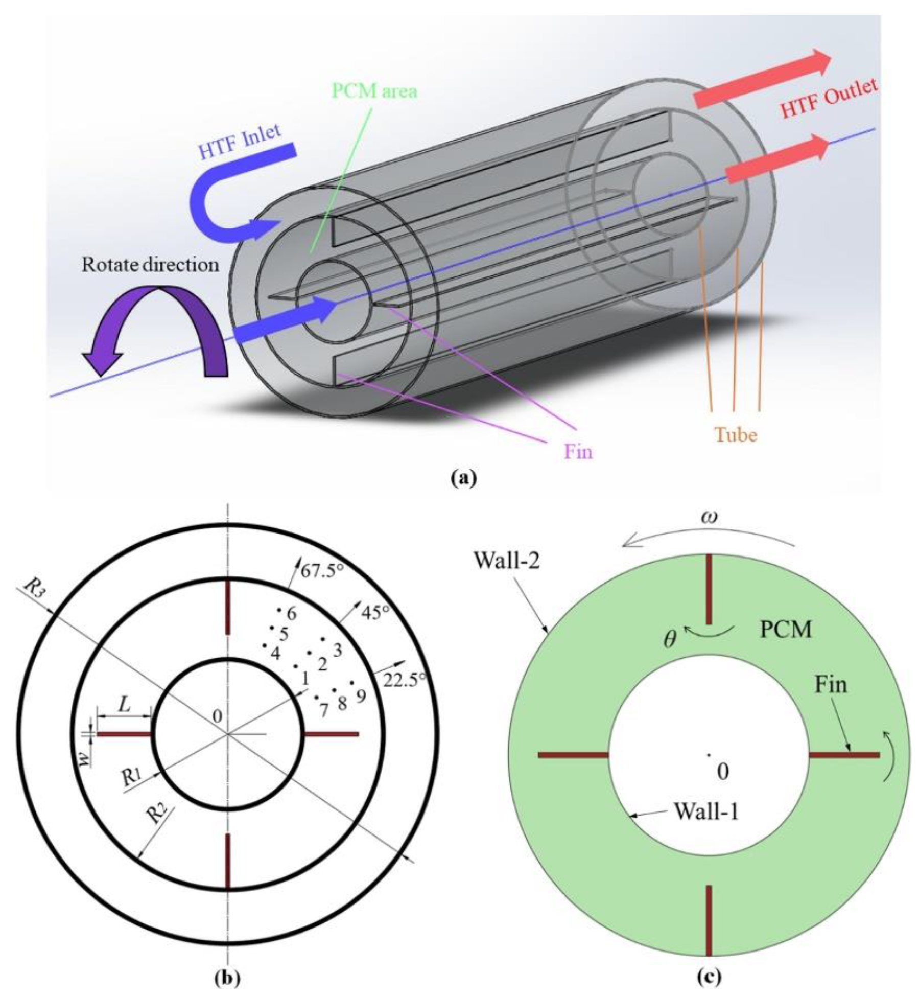
28] numerically studied the solidification of n-eicosane and RT-82 PCM in a horizontal triplex-tube LHTES system, as shown in Figure 1. The system was enhanced using four fins with optimized lengths, widths, and angles along with constant system rotational speed at 0.05, 0.1, 0.2, 0.5, and 0.1 rpm. It was found that as rotational speed increases, the solidification time decreases and the heat transfer rate increases. The results showed that rotation at 0.05 and 1 rpm reduced solidification time by 45.99% and 83.85%, respectively, compared to no rotation. Natural convection has little impact on the solidification of PCM, but the solidification rate with rotation is higher than that of PCM with only natural convection. Although the study optimized the design of the fins, there was no comparison to the system with no fins.
Soltani et al. [29] numerically studied both the charging and discharging processes in a horizontal shell-and-tube LHTES system with n-eicosane PCM. Four cases of copper radial fins were employed with 0, 4, 8, and 16 fins at rotational speeds of 0.1, 0.5, and 1 rpm. The greatest reduction in charging and discharging time was achieved by the case with four fins at a speed of 1 rpm, with a 73.13% and 83.21% reduction, respectively. Increasing the rotational speed decreased the charging times, but increasing the number of fins decreased the effect of natural convection and the rotational speed. In a following numerical study, Soltani et al. [30] analyzed the enhancement of fins, nanoparticles, and rotation on a horizontal shell-and-tube LHTES system with n-eicosane PCM. Cases were analyzed with four, six, and eight copper fins; copper nanoparticles volumetric fractions of 0.02 and 0.05; and rotational speeds of 0.1, 0.3, and 0.5 rpm. The case with eight fins, 0.5 rpm, and 0.05 volume fraction of nanoparticles had the fastest charging and discharging times, with 78.49% and 76.88% reduction in time compared to the unenhanced case; however, it decreased energy storage and release capacity by 5.1% and 6.5%, respectively. An optimized case was found with six fins, 0.02 nanoparticle volume fraction, and charging and discharging rotational speeds of 0.42 and 0.4 rpm. The optimal case decreased charging and discharging times by 73.67% and 69.73%, respectively, compared to the unenhanced system, with only 2.5% and 4.1% reduction in energy storage and release capacity, respectively. It was found that the enhancements with lower charging and discharging times had lower amounts of energy stored and released.
Based on the previous studies analyzed, the use of constant rotation has a significant impact on the charging and discharging process of LHTES systems. Other studies have analyzed alternative methods to constant rotation to reduce the additional energy consumption. Yu et al. [31] numerically studied the melting time of D-mannitol PCM in a rotating horizontal shell-and-tube LHTES system. Constant rotation speed at 0.01667, 0.08333, 0.16667, 0.5, and 1 rpm was compared to a case with no rotation. The authors also proposed a “single rotation” method where the system was rotated 180° at specific liquid fractions to enhance heat transfer equivalent to constant rotation. It was shown that increasing the rotational speed results in a higher melting speed, but continuing to increase the speed will result in insignificant reductions in melting time. “Single rotation” was found to have similar effect as the highest rotation speed at 0.5 liquid fraction, which decreased melting time by 811% compared to the unenhanced system. The “single rotation” was also found to reduce melting time by 116% compared to a static case with three radial fins. During charging, the PCM in the upper half of the system is dominated by natural convection, which melts faster than the lower half, which is dominated by conduction. By flipping the container at a specified liquid fraction, the cooler PCM at the bottom of the container can move to the top, where greater heat transfer takes place. A similar process was analyzed by Khoroshahi and Hossainpour [32], who numerically studied “step by step” rotation in a horizontal shell-and-tube LHTES system with RT-82 PCM. Eight cases of constant rotation were investigated between 0 and 0.0036 rpm. A novel “step by step” rotation included one scenario with counterclockwise turns with different numbers of stops and another scenario where the system is rotated once counterclockwise and then turned clockwise back to the initial position. The study determined that constant rotation does not have a significant impact on melting time because of the lack of natural convection vortex formation. An optimized “step by step” case was found, where the container was not rotated for a duration of 190 min and then was rotated 180°. This process was then repeated two more times, which resulted in a 15.5% reduction in melting time compared to the fixed case. This study may have concluded that there was no significant increase in melting time from constant rotation because the rotational speeds chosen were slow compared to other studies. The same authors, Khoroshahi and Hossainpour [33], further analyzed the “step by step” rotation method in the same system enhanced with two, three, and four aluminum fins compared to a no-fin case. The fins designed in the study fully section off the PCM in the container, which decreased the melting time by not allowing hot PCM to exchange energy with colder regions during rotation. An optimal case with four fins at 90° and two vertical stops at an angle difference of 180° was determined. The optimal case decreased melting time by 72% and increased the energy stored after 167.67 min by 115% compared to the fixed and no-fin storage. The previous study by the authors used constant rotation, but constant rotation was not used with full-scale fins. The effect of full-scale fins with constant rotation should be further investigated. Zheng et al. [34] numerically analyzed the melting of paraffin PCM in a rotating horizontal shell-and-tube LHTES system. A static case was compared to rotational cases of 1, 2, 4, 8, and 16 rpm. Rotation was started only after the PCM around the fins reached melting temperature to prevent the fins from hitting the solid PCM. As determined with other studies, increasing the rotational speed increases the melting rate. At 16 rpm, a 46.96% reduction in melting time and 79.02% increase in thermal energy storage rate was achieved compared to the static case. The study recommends that 2 rpm should be the lowest rotational speed used. A complimentary experimental validation showed 1.5 W was required for rotation of the system.
There are many computational studies on rotation in LHTES systems; however, due to the complexity of the systems, there is little attention towards experimental work. Fathi and Mussa [
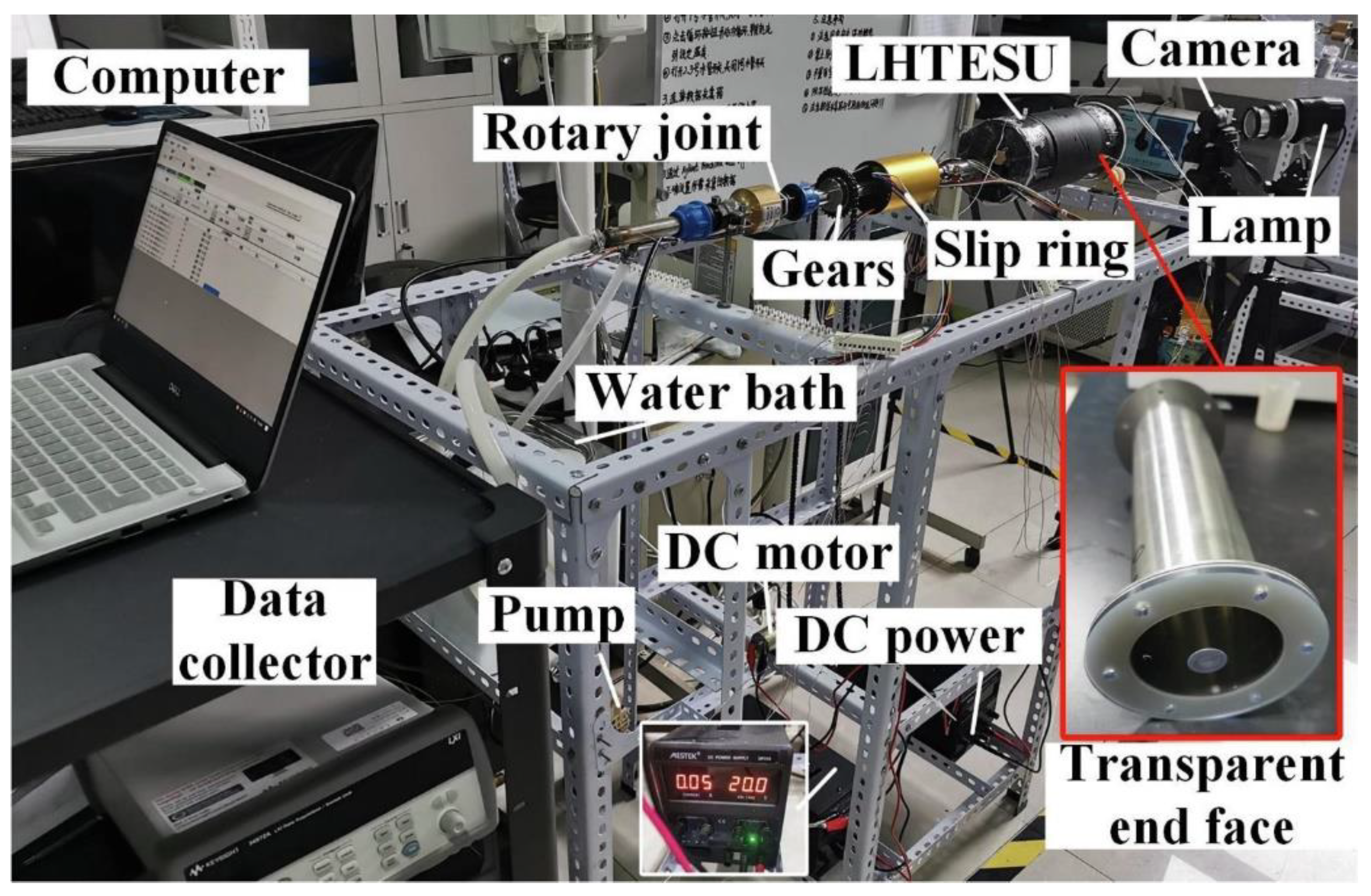
35] experimentally analyzed the rotation of a horizontal shell-and-tube LHTES system with paraffin wax PCM. Rotational speeds of 3, 6, and 9 rpm both clockwise and counterclockwise were studied. No significant difference in the melting time was found when comparing the still case to the rotating cases. After 10.75 h the 9-rpm case had an 8% increased liquid fraction compared to the fixed case. The authors, however, did not fully analyze the melting time and did not fully charge the system. Another experimental study conducted by Yang et al. [
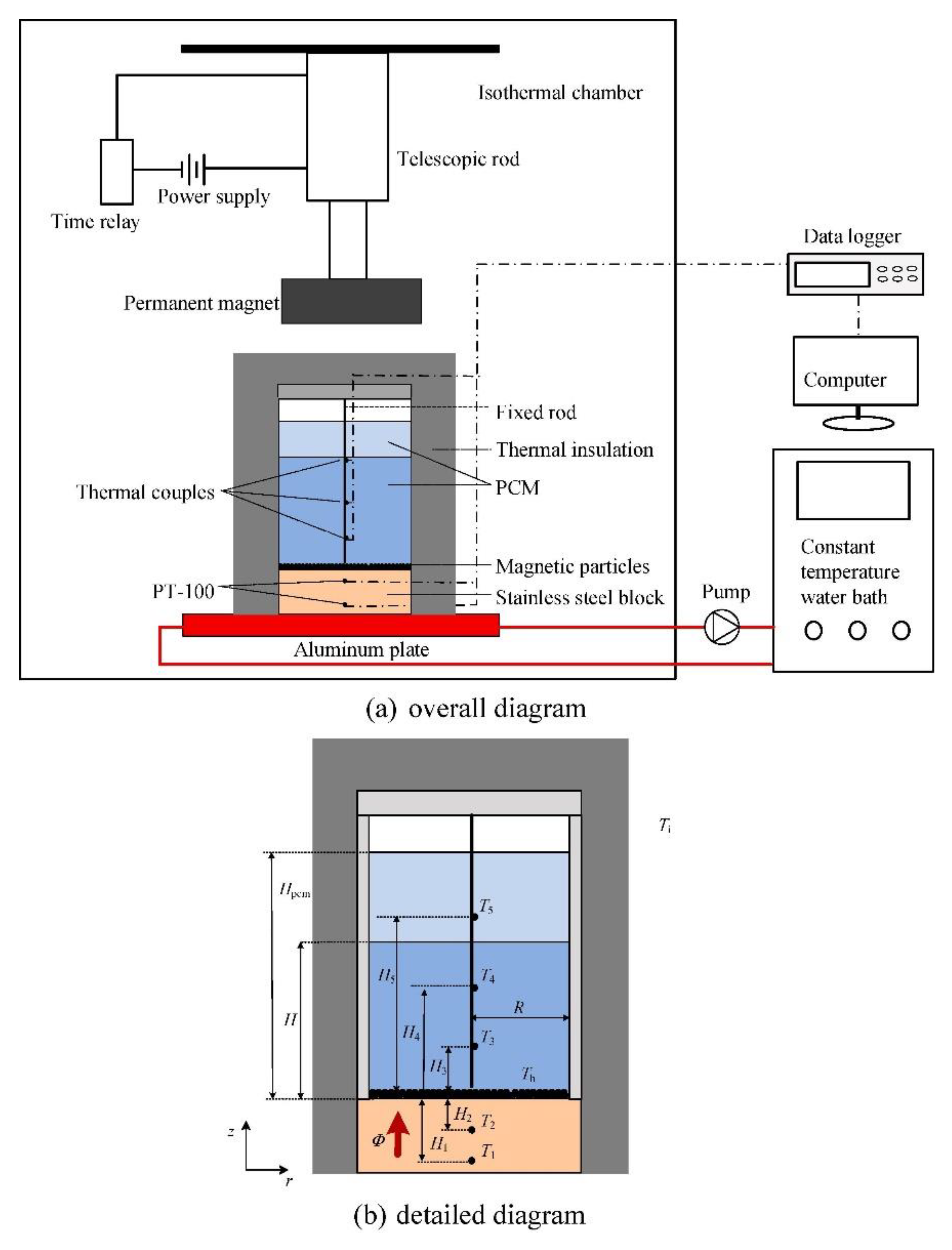
36] analyzed rotation in a horizontal shell-and-tube LHTES system with paraffin PCM. Three cases were studied including static, one flip 180° after 120 min, and 0.13 rpm. The flipping time was then optimized using dimensionless flipping times of 0.25, 0.375, 0.625, and 0.750. The constant rotation case decreased melting time by 19.35% compared to the static case. Flipping the system at an optimal point of 0.375 decreased melting time by 37.50% compared to the static case. A further energy analysis showed that flipping the system takes an additional 5 J of energy, whereas the constant rotation is an additional 1500 J. The energy required in both cases was considered negligible by the authors. The experimental methods and apparatus, shown in Figure 2, provide a thorough explanation of the components used to build the system, which can be used for future research.
Essa et al. [37] experimentally studied the enhancement of a tubular solar still with a rotating drum and paraffin wax PCM. The solar still was analyzed with copper oxide nanoparticle paint and rotation speed between 0.05 and 0.7 rpm. Without PCM and nanoparticle paint, the production of water from the solar still was increased by 121% at 0.1 rpm compared to the conventional system. When the system was enhanced with PCM, nanoparticle coating, and 0.3 rpm rotation, the productivity was increased by 218%.
The flipping method shows promising results when compared to constant rotation in both thermal performance and energy consumption. The flipping of a horizontal PCM container can be further improved by using eccentric HTF tubes. Modi et al. [38] numerically investigated eccentric tube locations within a horizontal shell-and-tube LHTES system with RT-50 PCM. The study found that eccentric position of the tube moving towards gravity improves melting performance but does not significantly improve after a dimensionless position of 0.75. Moving the tube away from gravity improves solidification but, as with melting, reaches an optimized position at −0.30. The opposite behavior of melting and solidification led to a novel 180-degree rotation method where the eccentric tube could be located at the bottom of the container during charging and flipped to the top during discharging. The concept for the eccentric tube rotational LHTES system is shown in Figure 3. An optimized case for rotation was found to be 0.30, which had a total melting and solidification time of 12.46 h compared to the concentric configuration, which had a combined time of 16 h.
A similar study by Soltani et al. [39] numerically analyzed eccentric tube locations in a rotational horizontal shell-and-tube LHTES system with n-eicosane PCM. In addition to eccentric tube locations, various diameter ratios of the container were compared, as well as constant rotation. Using the eccentric tube location while flipping the system between charging and discharging processes, the thermal performance of the system was increased compared to the central and constant rotational cases. The optimal case of 0.05 eccentricity with 180° rotation between charging and discharging achieved the fastest combined melting and solidification time for all the cases.
The studies focusing on rotational enhancement of LHTES systems are summarized in Table 1. The following are suggestions for future enhancements of rotational LHTES systems. To the authors’ knowledge, there has only been combined passive techniques and rotation using fins. Future studies should combine porous material and nanoparticle dispersion with rotational enhancement. In addition, rotation should be more thoroughly compared to passive techniques to see if the energy expenditure is cost effective. Additional experimental analysis on single rotation or flipping should be carried out. All of the studies reviewed used horizontal shell-and-tube LHTES systems. Rotation in vertical LHTES systems or other geometries/orientations should be examined.

2.2. Rotating Cylinder within PCM

Another rotational technique applied to LHTES systems is the use of a rotating cylinder located directly within the PCM. Selimefendigil and Öztop [40] numerically studied the fluid flow and heat transfer characteristics of RT-25 in a rectangular enclosure LHTES system with the addition of a rotating cylinder. The system, which is similar to those in the following studies, is shown in Figure 4. The system was analyzed in the melting process with angular rotational speeds of −7.5 to 7.5 rad/s, vertical locations of the cylinder from 0.25H to 0.75H, and two different sizes of cylinders, 0.05H and 0.1H. The study determined that the average Nusselt number increases by 22.50% for an angular rotational speed of 7.5 rad/s compared to the no-rotation case. In addition, spatial average heat transfer is 19.8% higher for the stationary cylinder and increases 10% for clockwise rotation of the larger cylinder. The study did not include an analysis of the rotating cylinder on discharging.
A similar study was conducted by Farahani et al. [
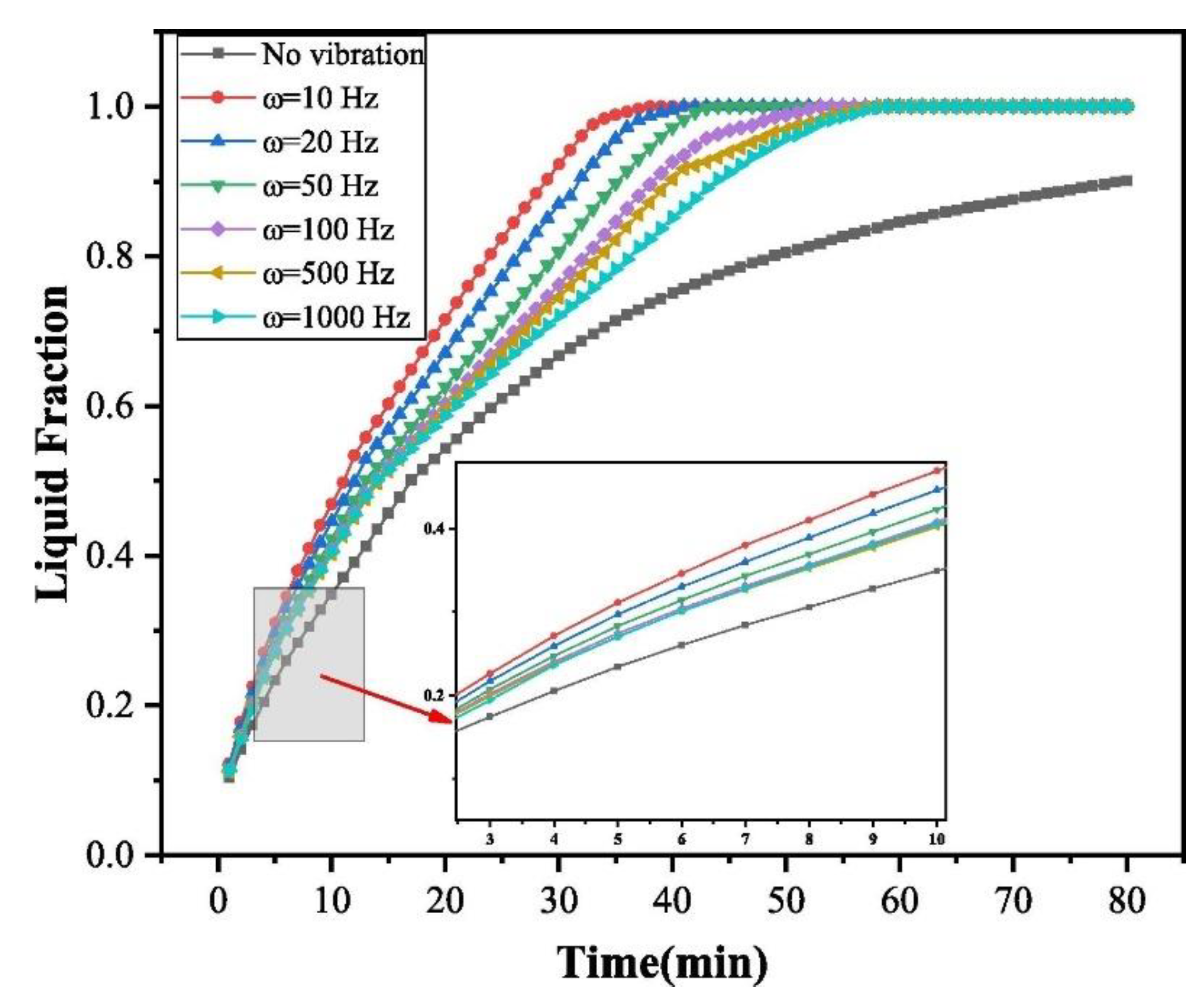
41] on a rectangular enclosure LHTES system with lauric acid PCM enhanced with rotating and oscillating cylinders. The system was analyzed with zero to four cylinders in different arrangements in the system with rotational speeds from −10 to 10 rad/s and oscillating frequencies of 0.1, 0.5, 1, 5, and 50 Hz. It was found that rotation of the cylinders decreased melting time most effectively at −3 and 10 rad/s compared to the stationary case. Increasing the cylinder oscillation range increased melting time, and increasing frequency decreased melting time. The most effective case was two cylinders horizontally placed in the system. In a numerical analysis by Qasem et al. [42], the effect of a rotating cylinder and wavy-walled rectangular enclosure LHTES system was analyzed on nano-PCM. Rotational speeds of −5 (clockwise) to 5 rad/s as well as number of undulations in the wall from one to four were studied. It was determined that the cylinder should rotate in the same flow direction as natural convection (clockwise). At −5 rad/s, the melting speed increases by 88% compared to no rotation. The undulation number was also found to be most efficient at 1. Al-Kouz et al. [
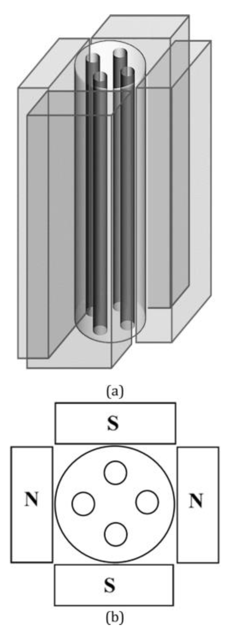
43] numerically studied a rectangular enclosure LHTES system enhanced with a rotating cylinder and external magnetic field. The cylinder was rotated at speeds of −10, 5, and 10 rad/s at vertical locations of 0.025, 0.05, and 0.075 within the enclosure. An external magnetic field was applied with Hartmann numbers of 0, 5, and 10. The rotation of the cylinder was found to increase the heat transfer rate up to 21.2% compared to a static case; however, the external magnetic field was found to decrease heat transfer. The authors determined that vertical placement of the cylinder can be used to optimize heat transfer.
A similar heat transfer enhancement technique has been applied to the HTF in PCM-packed bed systems. This can be seen by introducing rotating cylinders [44,45], surfaces [46,47], and disks [48] to the HTF flow before reaching the PCM. Another study analyzed the mixed convection of water and nano-encapsulated PCM with a rotating cylinder [49].
Table 2 summarizes the studies on PCM with rotating cylinders. To the authors’ knowledge, there have been no experimental studies on this enhancement technique, which suggests that the findings should be verified through experimental testing.

2.3. Scraped Surface

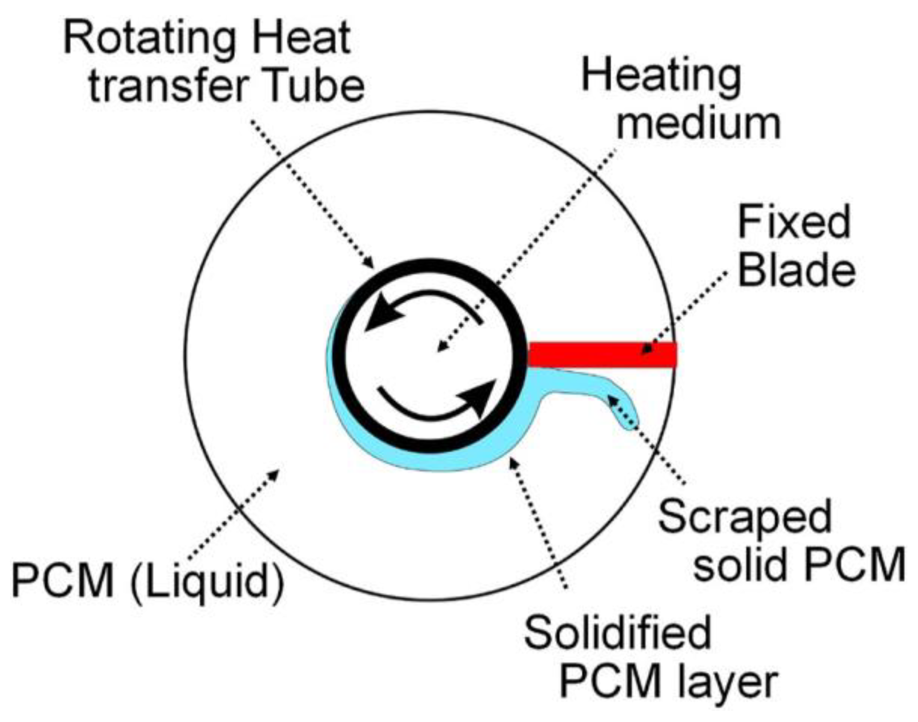
The concept of rotation can be applied to scraped surface heat exchangers for LHTES systems. During the solidification process, PCM begins to solidify on the heat transfer surface. The low thermal conductivity of the PCM in its solid state acts as insulation between the molten PCM and the heat transfer surface. By actively scraping the solidified PCM from the heat transfer wall, the thermal resistance between the HTF and molten PCM is decreased, which increases the discharging rate. This technique has been applied in the following studies. Maruoka et al. [50] experimentally studied the solidification of sodium acetate tri-hydrate PCM in a vertical shell-and-tube LHTES system with a rotating HTF tube and fixed blade. During the discharging process, the HTF tube was rotated at 100, 300, and 500 rpm, which allowed for the solidified PCM to be scraped off the HTF tube. The proposed schematic of the system is shown in Figure 5. The study showed that as rotation rate increases, the overall heat transfer coefficient increases, reaching more than 2000 W/m2K at 500 rpm. The heat transfer rate decreased at a heat release ratio of more than 80–90% due to the PCM around the HTF tube solidifying.
A similar study with a unique LHTES system was conducted by Egea et al. [51]. The authors experimentally analyzed the heat release rate of RT-44HC PCM in a vertical cylindrical LHTES system with the HTF surrounding the PCM container. Three sets of rotating blades were connected to a pipe, which rotated to scrape PCM off the outer wall of the container. The schematic of the system is shown in Figure 6. Rotating speeds of 3, 5, and 7.5 rpm were utilized and compared to a non-scraping mode at 0 rpm. It was determined that the heat release rate is not significantly impacted by an increase in rotational speed. The scraping mode resulted in a 2–3 times higher heat release rate regardless of rotational speed.
Another application of the scraped surface technique is a rotating drum heat exchanger, which is proposed by Tombrink et al. [52]. The proposed design is a horizontal rotating drum partially submerged in a liquid PCM bath. An HTF is passed through a cavity within the rotating drum to extract thermal energy, which solidifies the PCM on the outer surface of the drum. The PCM is scraped off the outer surface of the drum before rotating back into the PCM bath. Tombrink et al. [52] experimentally analyzed this concept using decanoic acid PCM. Three different operational modes between 0.25 and 25 rpm were studied, which are shown in Figure 7. It was determined that minimizing the thickness of the solid PCM layer on the surface of the drum increases the heat transfer rate. In addition, the heat transfer rate is 142% higher for constant temperature difference between the PCM and HTF and constant rotational speed when compared to pure forced convection of PCM without solidification. By changing the rotational speed, the thermal output is able to be controlled, but the increase of heat transfer flattens out at higher rotational speeds.
Tombrink and Bauer [53] numerically confirmed the results of the previous experimental study. The results show only an 8% deviation in the heat transfer rate from the experiments for the transient numerical simulations above 4 rpm. Additionally, the authors analyzed high-temperature sodium nitrate PCM for steam generation at 0 to 300 rpm. When simulated with 300 rpm and a 150 K temperature difference between the HTF and the melting point of the PCM, results show that a surface-specific heat flux of up to 500 kW/m2 is achieved. This shows that the system is acceptable for steam generation. Utilizing the information from the experimental and numerical studies, Tombrink and Bauer [54] numerically optimized the horizontal rotating drum heat exchanger for use in steam generation and co-generation of electricity and heat using renewable energy. Utilizing the high-temperature PCM, water within the rotating drum can be converted to steam. The authors determined that the design parameters of the system are freely scalable for usage in industrial applications.
The studies focusing on scraped surface enhancement of LHTES systems are summarized in Table 3. The following are suggestions for future enhancements of scraped surface LHTES systems. The scraped surface technique has only been applied to the discharging process of PCM; however, the charging process needs to be enhanced as well to store thermal energy. A future study could perhaps employ scrapers that act as fins during charging. The optimization of energy input for rotation should be further investigated.

3. Vibration

Vibration can be used to improve the thermal response of PCMs in LHTES systems. This technique has been used to enhance heat transfer in single-phase fluids within heat exchangers. The impact of heat transfer in fluids is interesting mainly in the melting process of PCMs, where the process is driven by convection of molten PCM. To the authors’ knowledge, vibration has only been applied to the melting process of PCMs recently, and little focus has been on solidification. The inherent vibration associated with mechanical systems can be used to the advantage of thermal energy storage and thermal management.
Wu et al. [55] numerically analyzed the melting process of paraffin wax in a cubic heat sink enhanced with mechanical vibration. Vibration frequencies were tested between 0 and 1000 Hz, and the axis of vibration was oriented from 0 to π away from gravity. The study determined that increasing the vibration frequency increases the melting speed of the PCM; however, low to moderate frequencies are optimal because acceleration of the melting process slows down after 400 Hz. This can be seen in the reported results from Figure 8. Additionally, charging speed was the fastest when the axis of vibration was parallel to gravity (0 and π). Fundamentally, the vibration increased the mixing of the molten PCM and the time-averaged convective heat transfer rate.
A subsequent numerical study conducted by Zhou et al. [56] analyzed the effects of vibration on the melting of paraffin in a horizontal shell-and-tube LHTES system. Vibration frequencies ranged from 10 to 1000 Hz with vibrational amplitudes from 1.5 to 10 mm. The axis of vibration was tilted away from gravity between 0 and 90°. The study determined that low-frequency vibrations were more effective than high vibrations at decreasing the melting process duration (Figure 9). The static case, 10 Hz, and 1000 Hz melted in 134.3, 35.1, and 56.2 min, respectively. Increasing the amplitude was found to decrease the melting time. The testing conditions of 10 mm amplitude and 10 Hz decreased melting time by 84.7% compared to the static case. Furthermore, the most effective tilt of the vibrational axis was found to be 30° from gravity. The difference in findings between Wu et al. [55] and Zhou et al. [56] shows that the effect of vibration frequency may be dependent on the geometry of the system.
The passive fin technique was combined with vibration in a numerical study by Yu and Chen [57]. The authors combined a single steel 302 fin with mechanical vibration frequencies from 0 to 1000 Hz and amplitudes with Grashof numbers from 103 to 107 on paraffin wax PCM in a cubic enclosure. Similar results to Wu et al. [55] were found, where increasing the vibration frequency increased the melting rate; however, the effect of increasing frequency above 400 Hz became weak. The authors suggested that the most effective frequencies fall between 0 and 200 Hz. The increase of vibrational amplitude was also found to increase melting rate, although the authors noted safety concerns with increased amplitude if experimentally conducted. Furthermore, it was determined that an optimal fin length existed between 1/3 and 2/3 of the wall length of the enclosure. A numerical study by Wu et al. [58] analyzed the effect of vibration enhancement on the melting of paraffin PCM in a horizontal shell-and-tube LHTES system with six copper longitudinal fins. The authors cited Zhou et al. [56] for the use of low frequencies from 1 to 4 Hz and amplitudes from 10 to 40 mm. The study determined that increasing amplitude is more effective than increasing frequency. Increasing from 10 to 40 mm decreased the total melting time by 75% compared to the no-vibration system while increasing from 1 to 4 Hz decreased melting time by 68.7%. There was no comparison made between the enhancement of fins and vibration. Al Omari et al. [59] experimentally studied the effect of vibration on the cooling of hot water using gallium PCM in a cylindrical direct contact heat exchanger. Vertical sinusoidal vibration was applied at 20 and 50 Hz with amplitudes of 0.3, 0.5, and 0.7 mm. The 50 Hz and 0.7 mm amplitude case decreased time to reduce water temperature by 35 °C by 90% compared to the no-vibration case. Under the same conditions, 99% of heat loss by the water was absorbed by gallium compared to 60% when static. The remaining heat was lost to the surroundings.
Vibration has recently been studied in battery thermal management systems for electric vehicles. The goal is to reduce the surface temperature of the battery while taking advantage of the vibration caused by the road. Du and Chen [60] numerically analyzed the effect of vibration on a n-octadecane PCM-based thermal management system for lithium ion batteries in electric vehicles. PCM thickness (3–12 mm), vibration frequency (0 to 200 Hz), and vibration amplitude (0 to 120 mm) were studied along with two battery discharge rates. The PCM thickness was found to greatly reduce battery surface temperature at 7 and 9 mm by 45% and 49%, respectively, compared to the case with no PCM. The authors suggest using 7 mm due to weight constraints. It was found that increasing vibration frequency and amplitude decreases battery surface temperature. A frequency of 50 Hz decreased surface temperature by 30% compared to no vibration. After 80 mm amplitude was reached, increasing the amplitude further became insignificant. Joshy et al. [61] experimentally studied vibration on a square passive battery thermal management system using RT-35HC PCM. Vibration at frequencies of 20, 35, and 50 Hz and amplitudes of 30, 40, and 50 mm/s at various discharge rates for the battery pack were tested. Frequency was determined to play a greater role in increasing temperature in lower battery discharging rates, whereas in higher rates, frequency and amplitude are both significant. In contrast to the previous study, the authors found that increasing vibration amplitude and frequency increases battery surface temperature. Zhang et al. [62] experimentally studied the effect of vibration on a battery thermal management system with paraffin composite PCM with expanded graphite or graphene nanoparticles. Tests were conducted for vibration amplitudes of 2 to 4 mm, frequencies of 10 to 30 Hz, and discharge rates of 3C and 5C. The paraffin composite PCM was tested with 10 wt% expanded graphite, 10 wt% graphene, and 20 wt% expanded graphite. An optimal case with 20 Hz and 20% expanded graphite was found to be most effective at cooling the surface of the battery. The vibration was found to enhance the dispersion and collision of the nanoparticles throughout the PCM. In addition, smaller vibration amplitudes are better for lower battery temperature.
The studies investigating vibration-enhanced LHTES systems are summarized in Table 4. Based on the review of recent literature focused on vibration enhancement of LHTES systems, future suggestions are as follows. The role of vibration in the discharging process should be studied. A greater comparison between active vibration and passive techniques should be made to determine the efficacy of vibration. Few studies have shown energy input for vibration, so future studies should factor in the energy utilized for vibration. More studies should combine the use of active vibration and passive techniques. Furthermore, the effect of vibration on different geometries of LHTES systems needs to be further investigated. The role of amplitude and frequency on battery surface temperature when mediated by PCM needs to be verified because of conflicting results.

4. Jet Impingement

Jet impingement is an active heat transfer enhancement technique where a stream of a gas or liquid is forced perpendicular or at an angle onto a surface. The fluid can be used to transfer thermal energy to or from the surface. In recent studies, the PCM has either been used as the impinging surface where the jet is focused or combined with the fluid stream as a PCM slurry.
For PCM use as the impinging surface, the jet can be used for either melting or solidification of the PCM. Bharanitharan et al. [63] numerically studied jet impingement of exhaust gas with various PCMs for waste heat recovery applications. Karami et al. [64] numerically analyzed the drying process of a moist porous material with micro-encapsulated PCM dispersed throughout with an impinging air jet for drying applications in industry (Figure 10). Faghiri et al. [65] experimentally studied the drop impact dynamics for direct-contact heat exchange between an impinging intermediate boiling fluid droplet and molten PCM for LHTES. Selimefendigil and Öztop [66] numerically analyzed convective heat transfer enhancement of nano-enhanced fluid with magnetic field and multi-jet impingement on a micro-encapsulated PCM-packed bed system. Based on review of the literature, the use of jet impingement has yet to be implemented on traditional LHTES systems.
Micro-encapsulated PCM can also be combined with the fluid stream to create a slurry. These are most commonly used in electronics cooling applications. Zhang et al. [67] experimentally studied the heat transfer of micro-encapsulated PCM slurry as the impinging fluid compared to water. It was shown that the latent heat of the PCM increased the heat transfer compared to water. Mohammadpour et al. [68] numerically analyzed the heat transfer of nano-encapsulated PCM slurry using dual-circular synthetic jets on a micro-channel heat sink. Synthetic jets are comparable to impinging jets but require less power. Abhijith and Venkatasubbaiah [69] numerically compared the heat transfer enhancement of n-eicosane and n-octadecane micro-encapsulated PCM slurries in a confined slot jet. The results showed that the n-eicosane slurry enhanced heat transfer by 72% compared to plain water, which outperformed n-octadecane. Mohaghegh et al. [70] numerically compared jet impingement of nanoparticle and nano-encapsulated PCM slurries, which resulted in enhancement of thermal performance of 16% and 7%, respectively, compared to water.

5. Injection

Injection is another active heat transfer enhancement method typically used in single-phase flow heat exchangers. This technique is widely demonstrated in recent works [71,72,73] with application in solar collectors as well [74]. In LHTES systems, injection involves pumping gas or air bubbles through the PCM to enhance natural convection heat transfer during melting and solidification.
A comprehensive three-part study was conducted on the heat transfer enhancement of an LHTES system using air bubble injection through PCM. In the first study, Choi et al. [75] experimentally analyzed the effect of air bubble injection on heat penetration through n-octadecane PCM (PARAFOR 18–97, Sasol) walls for building applications. Two cases were conducted, one with no bubbles and one with air bubbles injected into the PCM from the bottom of the container at 0.25 L/min starting 30 min after heat was applied. Due to the lower density of the PCM, the bottom of the container was filled with water in the bubble test to prevent solid PCM from blocking the air nozzles. The melting rate and latent heat storage of the PCM was 28% and 11% higher in the case with bubbles compared to no bubbles. The difference in the melting process is shown in Figure 11. An energy analysis determined that the extra energy for providing bubbles was only 1% of the increased latent heat storage.
In a subsequent study, Choi et al. [76] experimentally studied the charging process of 1-octadecanol PCM in a rectangular cell LHTES system. Air bubbles were injected into the system at a constant flow rate of 0.1 L/min while HTF was passed through the system at 0.2, 0.4, and 0.6 L/min. The experimental apparatus is shown in Figure 12. The air bubbles had diameters of 2–3 mm. System charging time was decreased by 53%, 40%, and 37%, respectively, for the 0.2, 0.4, and 0.6 L/min cases compared to no bubbles. The energy used for bubble injection was less than 0.2 kJ for all cases.
The final study by Choi et al. [77] experimentally investigated the discharging process of the same system from the previous study [76]. The air bubbles were injected into the PCM at 0.00735 kg/s, while the HTF flow rate varied from 0.2 to 0.4 L/min at temperatures of 30 °C and 40 °C. The bubbles were found to improve the convective heat transfer rate during the discharging process, which increased the discharging rate by 6–12% compared to the case with no bubbles. The energy used for bubble injection was only 1.42% of the energy released from the PCM.
Active heat transfer enhancement techniques can also be employed to decrease the effects of supercooling of PCM. Supercooling is where the temperature of liquid PCM decreases below melting temperature without solidifying. Vibration and ultrasound as well as bubble injection can be used to reduce supercooling effects. Yang et al. [78] experimentally analyzed the reduction of supercooling of erythritol PCM by injection of nitrogen gas bubbles in test tubes. With the melting temperature of erythritol being 118 °C, the test tubes were placed in cooling bath temperatures ranging from 10 to 118 °C while nitrogen gas bubbles were injected into the molten PCM at 0 to 100 mL/min with bubble sizes of 0.5, 1, and 3 mm. The nitrogen gas bubble injection reduced the degree of supercooling by 5 °C and increased the latent heat of crystallization from 218 kJ/kg to 322.3 kJ/kg. Future studies should focus on scaling this technique for industrial applications.
The studies investigating injection-enhanced LHTES systems are summarized in Table 5. Injection has not been widely studied in LHTES systems and can be increasingly used in combination with passive techniques. Future studies should focus on the use of other gases besides air or liquid injection.

6. External Fields

External fields in the form of magnetic, electric, and ultrasonic fields can actively be applied to LHTES systems to improve their thermal performance. An in-depth review on external fields effects on PCMs can be cited from Wu et al. [79] to improve LHTES systems. Recent studies utilizing magnetic, electric, and ultrasonic fields within LHTES systems are introduced in this section.

6.1. Magnetic Fields

Magnetic fields can be used to control heat transfer through PCMs enhanced with magnetic nanoparticles or powders. A series of numerical studies have been conducted on external magnetic fields. Shi et al. [80] numerically analyzed the charging and discharging of paraffin A16 PCM enhanced with Fe3O4 nanoparticles in a vertical-shell-and-multi-tube LHTES system surrounded by quadrupole magnets (Figure 13). Charging was tested with magnetic field intensities of 0, 30, 50, and 70 mT with HTF temperatures from 300 to 320 K, while discharging was tested with intensities of 0, 50, and 70 mT with HTF temperatures of 273.5 and 278 K. The analysis determined that increasing the magnetic field intensity increases the charging rate by increasing natural convection of molten PCM. At magnetic field intensities of 50 mT, the duration of the charging and discharging processes were decreased by 81.4% and 53.19% compared to no magnetic field.
Ghalambaz et al. [81] numerically studied the melting process of electrically conductive PCM in a square enclosure with heated wall and a non-uniform magnetic field. The strength of the magnetic field was altered with Hartman numbers from 0 to 50, while the location of the magnetic field along the wall was variable. The increase of the magnetic field strength was found to suppress natural convection and decrease the liquid fraction. The melting with the magnet was more uniform and can be controlled by the location of the magnetic field source. Izadi et al. [82] numerically analyzed the melting process of paraffin enhanced with Al2O3 nanoparticles in a trapezoidal enclosure with a magnetic field. The strength of the magnetic field varied from Hartman numbers of 0 to 1000 at angles from −90° to 90°. The volume fraction of the nanoparticles was studied between 0.01 and 0.1. As shown in the previous study discussed, the increase of Hartman number decreased the natural convection flow. The most effective angle of the magnetic field for melting speed was −45° and 45°, but it only increased 3% compared to no tilt. In addition, increasing the nanoparticle volume fraction increased the melting rate of the PCM due to increased thermal conductivity.
Many novel experimental works have also been completed on external magnetic fields in LHTES systems. Fan et al. [83] experimentally examined the melting process of 1-tetradecanol PCM enhanced with iron powders (0 to 1.5 wt%) in a vertical cylindrical LHTES unit. The unit was placed on a heating surface, which was varied in temperature while a permanent magnet attached to a telescopic rod periodically moved up and down above the system from 0 to 0.250 Hz. The system is shown in Figure 14. Increasing the alternating magnetic field and the iron powder mass fraction increased the enhancement of the system. The alternating magnetic field pulled the powder from the bottom of the container upward, which caused forced convection and decreased melting time by 15.8% compared to the unenhanced system.
In a subsequent study by the same authors, Fan et al. [84] experimentally and numerically analyzed the melting process of 1-dodecanol PCM enhanced with iron particles (0 to 1 wt%) in a cylindrical LHTES system. A permanent magnet was rotated around the system from 0 to 30 rpm. Increasing the rotational speed was found to increase the convection and melting rate, with a 22.9% reduction in melting time with 20 rpm, 1.0 wt% particles, and 35 °C HTF temperature. Increasing the particle wt% increased melting, but after 1.0 wt%, the increase becomes insignificant. Xing et al. [85] experimentally and theoretically examined the solidification and supercooling of water enhanced with carbon nanotubes and an external magnetic field for ice thermal energy storage. Four multi-walled carbon-nanotube-enhanced PCMs were used with mass ratios of 1:1, 2:1, 3:1, and 4:1 for Fe:C ratios, while the magnetic field intensity ranged from 0 to 200 mT. The authors stated that carbon nanotubes have a high thermal conductivity in the axial direction, where the magnetic field correctly aligns the nanotubes. It was determined that magnetic field intensity needs to be increased with Fe:C ratio to decrease solidification time. A 2:1 ratio was found to decrease solidification the most, with a 19.6% decrease compared to pure water.
External magnetic fields have also been used to enhance heat transfer of nano-encapsulated PCMs in water slurries. This technique was demonstrated by Alazzam et al. [86] and Fereidooni et al. [87].
The studies investigating LHTES systems enhanced with an external magnetic field are summarized in Table 6. The review of various studies shows different results from pure numerical analysis. The use of external magnetic fields in PCMs, based on these studies, is highly dependent on the geometry of the system, magnetic particle dispersion, and application technique of the magnetic field. Further studies should compare different types of external magnetic fields. The majority of studies focus on the melting of PCMs, where more should look at the enhancement of solidification.

6.2. Electric Fields

Electric fields are used to enhance heat transfer in dielectric PCMs. Dielectric PCMs are insulators to electric conduction but become polarized from electric fields. Selvakumar et al. [88] numerically studied the melting process of a dielectric PCM enhanced with an external electric field in a rectangular cavity LHTES system. The authors stated that dielectric PCMs include paraffins, n-alkanes, fatty acids, fatty acid esters, and so on. The electric Rayleigh number and Stefan number were studied from 0 to 3000 and 0.01 to 1, respectively, with electric charge injection from the bottom wall flowing to the grounded top wall. It was determined that increasing the Stefan and electric Rayleigh number increases the melting rate; however, enhancement is more significant at lower Stefan values. The highest reduction in melting time was found with electric Rayleigh number of 3000 with a Stefan value of 0.01 and was reduced 56.10% compared to the case with no electric field. A subsequent study by the same authors, Selvakumar and Vengadesan [89], numerically analyzed the melting of n-octadecane PCM enhanced with an electric field in a square cavity from the left to right walls. The electric Rayleigh number ranged from 0 to 50,000 and Rayleigh numbers of 1 × 10³, 1 × 10⁴, and 1 × 10⁵ were implemented. As shown by the previous study, increasing the electric Rayleigh number increases the charging speed with an 83% reduction in melting time compared to the no-electric-field case when enhanced with an electric Rayleigh number of 50,000 at a Rayleigh number of 1 × 10³.
A series of three experimental studies were conducted by the same authors on the effect of external fields on LHTES systems. Sun et al. [90] experimentally studied the melting process of n-octadecane in a cuboid enclosure, comparing the effect of hot and cold electrode with −20 to 20 kV. The study found that changing the polarity did not have an effect on the melting process, but the electric field did impact the convection stage of melting. When voltage was applied to the hot wall, the molten PCM was attracted, which had a negative effect on melting with a 30% decrease in liquid fraction at 20 kV compared to the case with no electric field. The opposite effect was demonstrated when voltage was applied to the cold wall, where the liquid fraction was enhanced by 44% at 20 kV when compared to the case with no electric field. The following experimental study by Sun et al. [91] determined the effect of an electrically charged copper HTF tube on the melting process of n-octadecane PCM in a cubic enclosure. Cases were analyzed with a grounded bottom wall with −25 to 25 kV and with four grounded sidewalls with −15 and −25 kV. It was found that Coulomb force is dominant in melting heat transfer in the electric field cases, but the applied field must be greater than 7.5 kV for enhancement to be present. The best-case scenario was four grounded sidewalls with −25 kV, which reduced the melting time by 68.0% compared to no electric field, with only 3.03 × 10⁻³ W consumed. Another study by Sun et al. [92] experimentally analyzed the combination of nano-enhanced octadecane PCM and electric field in a cubic enclosure. The PCM was enhanced with 0, 0.5, 1, and 2 wt% nanographene sheets with an electric field from −10 to 10 kV. Applying the nanographene sheets at 2 wt% increased the thermal conductivity of the PCM with an enhancement of 33.6% absorbed energy compared to the pure PCM after melting. When the nano-enhanced PCM was combined with an electric field, the maximum absorbed thermal energy was found to be 124.8% at −10 kV compared to the unenhanced case. A positive voltage resulted in lower absorbed thermal energy because the negative charge of the nano-graphene was attracted to the bottom wall of the container. Nakhla and Cotton [93] experimentally studied the effect of electrohydrodynamic forces on the melting process of octadecane PCM in a vertical rectangular container. The system was enhanced with 30 brass cylinders connected to a high-voltage amplifier and ground to produce an electric field at +3 and +6 kV. The main method of enhancement was the splitting of the main gravity convection current into multiple convection cells between the electrodes driven by the electric field. The 6 kV case charging time was reduced by 1.7 times compared to the case with no electric field.
Electric fields have also been implemented to control the supercooling of PCMs [94] as well as heat transfer enhancement with nano-encapsulated PCM slurries [95]. The studies investigating LHTES systems enhanced with an external electric field are summarized in Table 7. As with external magnetic fields, the effect of the electric field on heat transfer in PCMs is highly dependent on the technique of application and geometry of the system. A majority of the studies analyzed the melting process when enhanced with electric fields, which shows that the discharging process should be studied in greater detail. Almost all of the reviewed studies used octadecane PCM; therefore, future studies should focus on a broader range of PCMs.

6.3. Ultrasonic Fields

External ultrasonic fields are similar to vibrational enhancement of LHTES systems; however, ultrasonic waves are characterized by a frequency greater than 20 kHz. Xu et al. [96] experimentally compared the effect of copper foam and ultrasonic vibration enhancement on the melting process of gallium as a PCM in a rectangular enclosure. The gallium embedded with 20 pores per inch (PPI) and 80% porosity copper foam decreased the melting time by 10% compared to pure gallium. The ultrasonic vibration applied with 50 kHz and 30 W power decreased melting time by 17% compared to unenhanced gallium. Although it is beneficial for the authors to compare the passive heat transfer enhancement of copper foam to active ultrasonic vibration, further analysis should have been conducted on combined copper foam and ultrasonic vibration enhancement. Cui et al. [97] experimentally analyzed the melting process of paraffin PCM in a rectangular enclosure with combination enhancement of nanoparticles, copper foam, and ultrasonic field. The system was enhanced with TiO2 nanoparticles at 0 to 5 wt%, 20 PPI, and 80% porosity copper foam, and an ultrasonic field with power outputs of 0, 50, and 100 W. In addition, the operation time of the ultrasonic field was optimized to reduce energy consumption. It was found that increasing nanoparticle concentration and power input increases the thermal energy storage rate. The case with 5 wt% nanoparticles and 100 W achieved 46.50% time reduction in melting compared to the base case. Furthermore, to reduce energy consumption, the ultrasonic field should be introduced during the latent stage of the melting process.
Ultrasonic fields have also been used to improve solidification and supercooling. Daghoogi-Mobarakeh et al. [98] experimentally analyzed improved freezing of water and supercooling in a rectangular container using ultrasound. Ultrasound was applied during the freezing process at continuous, cyclic, and pulse rates. It was determined that optimized cyclic ultrasound with 3.52 W and 8.25 W at 5 s pulses every 2 min can start nucleation and help stop supercooling. The 3.52 W and 8.25 W tests resulted in energy savings of 12.4% and 10.8% compared to cases with no ultrasound.
The studies investigating LHTES systems enhanced with an external ultrasonic field are summarized in Table 8. There has been minimal investigation on LHTES systems with ultrasound, and research should be broadened in the future.

7. Conclusions

Recent studies focusing on active heat transfer enhancement techniques for increasing the thermal performance of latent heat thermal energy storage systems were reviewed. The main methods of active enhancement include mechanical aids, vibration, jet impingement, injection, and external fields. It is clear that active methods can be used to increase the charging and discharging rates of PCMs as well as aid in other aspects such as supercooling and temperature uniformity. A majority of studies focus on mechanical aids, while there is a lack of analysis on LHTES systems enhanced with jet impingement and ultrasonic fields. Additionally, most studies used organic PCMs with little attention on inorganic PCMs. The direction of research should be broadened to include more types of PCMs with active techniques. The conclusions for each technique are summarized as follows:
  • Mechanical Aids: Includes system rotation, rotating cylinder, and scraped surface enhancement to facilitate forced convection heat transfer. Rotation within LHTES systems requires complex designs to manufacture and maintain. Moving parts with molten PCM may pose safety risks. Rotation should be extensively compared to passive techniques to see if the additional energy input is cost effective.
  • Vibration: Increases the mixing of molten PCM. Requires complex designs and poses safety risks at high amplitudes and frequencies. Vibration inherent in machinery should be utilized to enhance heat transfer. The role of vibration in discharging needs to be analyzed.
  • Jet Impingement: Has the ability to produce high heat transfer coefficients. Little attention has been given to traditional LHTES systems with jet impingement, which should be the focus of future studies. The use of micro-encapsulated PCM slurries shows promise in electronics cooling applications.
  • Injection: Enhancement with injection provides improvement to natural convection heat transfer. Systems rely on the density difference of gas and PCM to prevent blockages in the injection nozzles. The enhancement of LHTES systems with injection should be analyzed on different gases other than air. Further analysis should be completed to compare passive techniques with injection to justify the complexity of the system.
  • External Fields: Includes electric, magnetic, and ultrasonic fields. Can be used to promote convection heat transfer but is highly dependent on system geometry. The effect of system geometry needs to be further studied with magnetic fields. External fields could conflict with other components of the system or electronics in the surroundings. Studies focusing on the effect of electric fields on discharging need to be completed and general research on ultrasound enhancement is lacking and should be broadened.
Few studies have made the comparison between active and passive techniques. The use of active techniques needs to be further compared with passive to determine if the increased thermal performance justifies the additional energy input. The LHTES systems reviewed are complex and costly compared to traditional passive techniques. Many studies mentioned their energy input and optimized the technique to decrease energy consumption. This is a feature that should be consistent in future analyses. The combination of active and passive techniques is also of interest. The active heat transfer enhancement field of LHTES systems is relatively new and should be expanded to other methods that are used in single-phase heat exchangers.

Author Contributions

Investigation, K.S.; writing—original draft preparation, K.S.; writing—review and editing, S.T.; supervision, S.T. All authors have read and agreed to the published version of the manuscript.

Funding

This research received no external funding.

Data Availability Statement

No new data were created or analyzed in this study. Data sharing is not applicable to this article.

Acknowledgments

The authors would like to thank Gannon University for supporting this work.

Conflicts of Interest

The authors declare no conflict of interest.

References

  1. Energy.Gov. Solar. 2023. Available online: https://www.energy.gov/solar (accessed on 17 May 2023).
  2. Lee, J.; Lin, K.-Y.A.; Jung, S.; Kwon, E.E. Hybrid renewable energy systems involving thermochemical conversion process for waste-to-energy strategy. Chem. Eng. J. 2023, 452, 139218. [Google Scholar] [CrossRef]
  3. Seyitini, L.; Belgasim, B.; Enweremadu, C.C. Solid state sensible heat storage technology for industrial applications—A review. J. Energy Storage 2023, 62, 106919. [Google Scholar] [CrossRef]
  4. Tiwari, V.; Rai, A.C.; Srinivasan, P. Parametric analysis and optimization of a latent heat thermal energy storage system for concentrated solar power plants under realistic operating conditions. Renew. Energy 2021, 174, 305–319. [Google Scholar] [CrossRef]
  5. Srinivasan, G.; Rabha, D.; Muthukumar, P. A review on solar dryers integrated with thermal energy storage units for drying agricultural and food products. Sol. Energy 2021, 229, 22–38. [Google Scholar] [CrossRef]
  6. Arslan, O.; Arslan, A.E.; Boukelia, T.E. Modelling and optimization of domestic thermal energy storage based heat pump system for geothermal district heating. Energy Build. 2023, 282, 112792. [Google Scholar] [CrossRef]
  7. Bastida, H.; De la Cruz-Loredo, I.; Ugalde-Loo, C.E. Effective estimation of the state-of-charge of latent heat thermal energy storage for heating and cooling systems using non-linear state observers. Appl. Energy 2023, 331, 120448. [Google Scholar] [CrossRef]
  8. Yang, M.; Moghimi, M.; Loillier, R.; Markides, C.; Kadivar, M. Design of a latent heat thermal energy storage system under simultaneous charging and discharging for solar domestic hot water applications. Appl. Energy 2023, 336, 120848. [Google Scholar] [CrossRef]
  9. Modi, N.; Wang, X.; Negnevitsky, M. Solar Hot Water Systems Using Latent Heat Thermal Energy Storage: Perspectives and Challenges. Energies 2023, 16, 1969. [Google Scholar] [CrossRef]
  10. He, M.; Wang, Y.; Li, D.; Zhang, M.; Wang, T.; Zhi, F.; Ji, X.; Ding, D. Recent applications of phase-change materials in tumor therapy and theranostics. Biomater. Adv. 2023, 147, 213309. [Google Scholar] [CrossRef]
  11. Yang, S.; Shao, X.-F.; Luo, J.-H.; Oskouei, S.B.; Bayer, Z.; Fan, L.-W. A novel cascade latent heat thermal energy storage system consisting of erythritol and paraffin wax for deep recovery of medium-temperature industrial waste heat. Energy 2023, 265, 126359. [Google Scholar] [CrossRef]
  12. Dzhonova-Atanasova, D.; Georgiev, A.; Nakov, S.; Panyovska, S.; Petrova, T.; Maiti, S. Compact Thermal Storage with Phase Change Material for Low-Temperature Waste Heat Recovery—Advances and Perspectives. Energies 2022, 15, 8269. [Google Scholar] [CrossRef]
  13. Liu, Y.; Zheng, R.; Li, J. High latent heat phase change materials (PCMs) with low melting temperature for thermal management and storage of electronic devices and power batteries: Critical review. Renew. Sust. Energy Rev. 2022, 168, 112783. [Google Scholar] [CrossRef]
  14. Diaconu, B.; Cruceru, M.; Anghelescu, L.; Racoceanu, C.; Popescu, C.; Ionescu, M.; Tudorache, A. Latent Heat Storage Systems for Thermal Management of Electric Vehicle Batteries: Thermal Performance Enhancement and Modulation of the Phase Transition Process Dynamics: A Literature Review. Energies 2023, 16, 2745. [Google Scholar] [CrossRef]
  15. Tofani, K.; Tiari, S. Nano-Enhanced Phase Change Materials in Latent Heat Thermal Energy Storage Systems: A Review. Energies 2021, 14, 3821. [Google Scholar] [CrossRef]
  16. Maldonado, J.M.; de Gracia, A.; Cabeza, L.F. Systematic review on the use of heat pipes in latent heat thermal energy storage tanks. J. Energy Storage 2020, 32, 101733. [Google Scholar] [CrossRef]
  17. Ghalambaz, M.; Aljaghtham, M.; Chamkha, A.J.; Abdullah, A.; Alshehri, A.; Ghalambaz, M. Anisotropic metal foam design for improved latent heat thermal energy storage in a tilted enclosure. Int. J. Mech. Sci. 2023, 238, 107830. [Google Scholar] [CrossRef]
  18. Tiari, S.; Hockins, A.; Shank, K. Experimental study of a latent heat thermal energy storage system assisted by varying annular fins. J. Energy Storage 2022, 55, 105603. [Google Scholar] [CrossRef]
  19. Khademi, A.; Shank, K.; Mehrjardi, S.A.A.; Tiari, S.; Sorrentino, G.; Said, Z.; Chamkha, A.J.; Ushak, S. A brief review on different hybrid methods of enhancement within latent heat storage systems. J. Energy Storage 2022, 54, 105362. [Google Scholar] [CrossRef]
  20. Jegadheeswaran, S.; Sundaramahalingam, A.; Pohekar, S.D. Alternative Heat Transfer Enhancement Techniques for Latent Heat Thermal Energy Storage System: A Review. Int. J. Thermophys. 2021, 42, 1–48. [Google Scholar] [CrossRef]
  21. Sarath, K.; Osman, M.F.; Mukesh, R.; Manu, K.; Deepu, M. A review of the recent advances in the heat transfer physics in latent heat storage systems. Therm. Sci. Eng. Prog. 2023, 42, 101886. [Google Scholar] [CrossRef]
  22. Diaconu, B.M.; Cruceru, M.; Anghelescu, L. A critical review on heat transfer enhancement techniques in latent heat storage systems based on phase change materials. Passive and active techniques, system designs and optimization. J. Energy Storage 2023, 61, 106830. [Google Scholar] [CrossRef]
  23. Webb, R.L.; Kim, N.-H. Principles of Enhanced Heat Transfer; Taylor & Francis: New York, NY, USA; London, UK, 2005. [Google Scholar]
  24. D’addio, L.; Carotenuto, C.; Di Natale, F.; Nigro, R. Heating and cooling of hazelnut paste in alternate blades scraped surface heat exchangers. J. Food Eng. 2013, 115, 182–189. [Google Scholar] [CrossRef]
  25. Rao, C.S.; Hartel, R.W. Scraped surface heat exchangers. Crit. Rev. Food Sci. Nutr. 2006, 46, 207–219. [Google Scholar] [CrossRef]
  26. Tiari, S.; Qiu, S. Three-dimensional simulation of high temperature latent heat thermal energy storage system assisted by finned heat pipes. Energy Convers. Manag. 2015, 105, 260–271. [Google Scholar] [CrossRef]
  27. Tiari, S.; Qiu, S.; Mahdavi, M. Discharging process of a finned heat pipe–assisted thermal energy storage system with high temperature phase change material. Energy Convers. Manag. 2016, 118, 426–437. [Google Scholar] [CrossRef]
  28. Huang, X.; Li, F.; Xiao, T.; Guo, J.; Wang, F.; Gao, X.; Yang, X.; He, Y.-L. Investigation and optimization of solidification performance of a triplex-tube latent heat thermal energy storage system by rotational mechanism. Appl. Energy 2023, 331, 120435. [Google Scholar] [CrossRef]
  29. Soltani, H.; Soltani, M.; Karimi, H.; Nathwani, J. Heat transfer enhancement in latent heat thermal energy storage unit using a combination of fins and rotational mechanisms. Int. J. Heat Mass Transf. 2021, 179, 121667. [Google Scholar] [CrossRef]
  30. Soltani, H.; Soltani, M.; Karimi, H.; Nathwani, J. Optimization of shell and tube thermal energy storage unit based on the effects of adding fins, nanoparticles and rotational mechanism. J. Clean. Prod. 2022, 331, 129922. [Google Scholar] [CrossRef]
  31. Yu, X.; Jiang, R.; Li, Z.; Qian, G.; Wang, B.; Wang, L.; Huang, R. Synergistic improvement of melting rate and heat storage capacity by a rotation-based method for shell-and-tube latent thermal energy storage. Appl. Therm. Eng. 2023, 219, 119480. [Google Scholar] [CrossRef]
  32. Khosroshahi, A.J.; Hossainpour, S. Investigation of storage rotation effect on phase change material charging process in latent heat thermal energy storage system. J. Energy Storage 2021, 36, 102442. [Google Scholar] [CrossRef]
  33. Khosroshahi, A.J.; Hossainpour, S. A numerical investigation on the finned storage rotation effect on the phase change material melting process of latent heat thermal energy storage system. J. Energy Storage 2022, 55, 105461. [Google Scholar] [CrossRef]
  34. Zheng, Z.-J.; Sun, Y.; Chen, Y.; He, C.; Yin, H.; Xu, Y. Study of the melting performance of shell-and-tube latent heat thermal energy storage unit under the action of rotating finned tube. J. Energy Storage 2023, 62, 106801. [Google Scholar] [CrossRef]
  35. Fathi, M.I.; Mussa, M.A. Experimental study on the effect of tube rotation on performance of horizontal shell and tube latent heat energy storage. J. Energy Storage 2021, 39, 102626. [Google Scholar] [CrossRef]
  36. Yang, C.; Zheng, Z.-J.; Cai, X.; Xu, Y. Experimental study on the effect of rotation on melting performance of shell-and-tube latent heat thermal energy storage unit. Appl. Therm. Eng. 2022, 215, 118877. [Google Scholar] [CrossRef]
  37. Essa, F.; Abdullah, A.; Alawee, W.H.; Alarjani, A.; Alqsair, U.F.; Shanmugan, S.; Omara, Z.; Younes, M. Experimental enhancement of tubular solar still performance using rotating cylinder, nanoparticles’ coating, parabolic solar concentrator, and phase change material. Case Stud. Therm. Eng. 2022, 29, 101705. [Google Scholar] [CrossRef]
  38. Modi, N.; Wang, X.; Negnevitsky, M. Melting and solidification characteristics of a semi-rotational eccentric tube horizontal latent heat thermal energy storage. Appl. Therm. Eng. 2022, 214, 118812. [Google Scholar] [CrossRef]
  39. Soltani, H.; Soltani, M.; Nathwani, J. Optimization of thermal energy storage: Evaluation of natural convection and melting-solidification time of eccentricity for a rotational shell-and-tube unit. J. Energy Storage 2023, 58, 106423. [Google Scholar] [CrossRef]
  40. Selimefendigil, F.; Öztop, H.F. Mixed convection in a PCM filled cavity under the influence of a rotating cylinder. Sol. Energy 2020, 200, 61–75. [Google Scholar] [CrossRef]
  41. Farahani, S.D.; Mohammadi, S.; Farahani, A.D.; Smaisim, G.F. Control of the melting process in a rectangular energy storage chamber filled with phase change material in the presence of an oscillating and rotating cylinder. J. Energy Storage 2023, 60, 106628. [Google Scholar] [CrossRef]
  42. Qasem, N.A.; Abderrahmane, A.; Ahmed, S.; Younis, O.; Guedri, K.; Said, Z.; Mourad, A. Effect of a rotating cylinder on convective flow, heat and entropy production of a 3D wavy enclosure filled by a phase change material. Appl. Therm. Eng. 2022, 214, 118818. [Google Scholar] [CrossRef]
  43. Al-Kouz, W.; Aissa, A.; Devi, S.S.U.; Prakash, M.; Kolsi, L.; Moria, H.; Jamshed, W.; Younis, O. Effect of a rotating cylinder on the 3D MHD mixed convection in a phase change material filled cubic enclosure. Sustain. Energy Technol. Assess. 2022, 51, 101879. [Google Scholar] [CrossRef]
  44. Ouri, H.; Selimefendigil, F.; Bouterra, M.; Omri, M.; Alshammari, B.M.; Kolsi, L. MHD hybrid nanofluid convection and phase change process in an L-shaped vented cavity equipped with an inner rotating cylinder and PCM-packed bed system. Alex. Eng. J. 2023, 63, 563–582. [Google Scholar] [CrossRef]
  45. Selimefendigil, F.; Öztop, H.F. Hybrid nanofluid convection and phase change process in an expanded channel under the combined effects of double rotating cylinders and magnetic field. J. Mol. Liq. 2022, 368, 120364. [Google Scholar] [CrossRef]
  46. Ghachem, K.; Selimefendigil, F.; Öztop, H.F.; Alhadri, M.; Kolsi, L.; Alshammari, N. Impacts of rotating surface and area expansion during nanofluid convection on phase change dynamics for PCM packed bed installed cylinder. Alex. Eng. J. 2022, 61, 4159–4173. [Google Scholar] [CrossRef]
  47. Ghachem, K.; Selimefendigil, F.; Öztop, H.F.; Almeshaal, M.; Alhadri, M.; Kolsi, L. Effects of magnetic field, binary particle loading and rotational conic surface on phase change process in a PCM filled cylinder. Case Stud. Therm. Eng. 2021, 28, 101456. [Google Scholar] [CrossRef]
  48. Selimefendigil, F.; Öztop, H.F.; Doranehgard, M.H.; Karimi, N. Phase change dynamics in a cylinder containing hybrid nanofluid and phase change material subjected to a rotating inner disk. J. Energy Storage 2021, 42, 103007. [Google Scholar] [CrossRef]
  49. Sadr, A.N.; Shekaramiz, M.; Zarinfar, M.; Esmaily, A.; Khoshtarash, H.; Toghraie, D. Simulation of mixed-convection of water and nano-encapsulated phase change material inside a square cavity with a rotating hot cylinder. J. Energy Storage 2022, 47, 103606. [Google Scholar] [CrossRef]
  50. Maruoka, N.; Tsutsumi, T.; Ito, A.; Hayasaka, M.; Nogami, H. Heat release characteristics of a latent heat storage heat exchanger by scraping the solidified phase change material layer. Energy 2020, 205, 118055. [Google Scholar] [CrossRef]
  51. Egea, A.; García, A.; Herrero-Martín, R.; Pérez-García, J. Experimental performance of a novel scraped surface heat exchanger for latent energy storage for domestic hot water generation. Renew. Energy 2022, 193, 870–878. [Google Scholar] [CrossRef]
  52. Tombrink, J.; Jockenhöfer, H.; Bauer, D. Experimental investigation of a rotating drum heat exchanger for latent heat storage. Appl. Therm. Eng. 2021, 183, 116221. [Google Scholar] [CrossRef]
  53. Tombrink, J.; Bauer, D. Simulation of a rotating drum heat exchanger for latent heat storage using a quasistationary analytical approach and a numerical transient finite difference scheme. Appl. Therm. Eng. 2021, 194, 117029. [Google Scholar] [CrossRef]
  54. Tombrink, J.; Bauer, D. Demand-based process steam from renewable energy: Implementation and sizing of a latent heat thermal energy storage system based on the Rotating Drum Heat Exchanger. Appl. Energy 2022, 321, 119325. [Google Scholar] [CrossRef]
  55. Wu, G.; Chen, S.; Zeng, S. Effects of mechanical vibration on melting behaviour of phase change material during charging process. Appl. Therm. Eng. 2021, 192, 116914. [Google Scholar] [CrossRef]
  56. Zhou, W.; Mohammed, H.I.; Chen, S.; Luo, M.; Wu, Y. Effects of mechanical vibration on the heat transfer performance of shell-and-tube latent heat thermal storage units during charging process. Appl. Therm. Eng. 2022, 216, 119133. [Google Scholar] [CrossRef]
  57. Yu, Y.; Chen, S. Utilize mechanical vibration energy for fast thermal responsive PCMs-based energy storage systems: Prototype research by numerical simulation. Renew. Energy 2022, 187, 974–986. [Google Scholar] [CrossRef]
  58. Wu, Y.; Luo, M.; Chen, S.; Zhou, W.; Yu, Y.; Zhou, Z. Numerical simulation study of the effect of mechanical vibration on heat transfer in a six-fin latent heat thermal energy storage unit. Int. J. Heat Mass Transf. 2023, 207, 123996. [Google Scholar] [CrossRef]
  59. Al Omari, S.; Ghazal, A.; Elnajjar, E.; Qureshi, Z. Vibration-enhanced direct contact heat exchange using gallium as a solid phase change material. Int. Commun. Heat Mass Transf. 2021, 120, 104990. [Google Scholar] [CrossRef]
  60. Du, W.; Chen, S. Effect of mechanical vibration on phase change material based thermal management module of a lithium-ion battery at high ambient temperature. J. Energy Storage 2023, 59, 106465. [Google Scholar] [CrossRef]
  61. Joshy, N.; Hajiyan, M.; Siddique, A.R.M.; Tasnim, S.; Simha, H.; Mahmud, S. Experimental investigation of the effect of vibration on phase change material (PCM) based battery thermal management system. J. Power Sources 2020, 450, 227717. [Google Scholar] [CrossRef]
  62. Zhang, W.; Li, X.; Wu, W.; Huang, J. Influence of mechanical vibration on composite phase change material based thermal management system for lithium-ion battery. J. Energy Storage 2022, 54, 105237. [Google Scholar] [CrossRef]
  63. Bharanitharan, K.; Kang, S.-W.; Sanjay, K.; Senthilkumar, S. A combined technique using phase change material and jet impingement heat transfer for the exhaust heat recovery applications—A numerical approach. J. Energy Storage 2022, 55, 105580. [Google Scholar] [CrossRef]
  64. Karami, A.; Kowsary, F.; Hanafizadeh, P.; Nejad, A.M. Enhancement of convective drying of a moist porous material with impinging slot jet by implementation of micro-encapsulated phase change material: A numerical feasibility study. Int. J. Heat Mass Transf. 2022, 191, 122828. [Google Scholar] [CrossRef]
  65. Faghiri, S.; Mohammadi, O.; Hosseininaveh, H.; Shafii, M.B. The impingement of liquid boiling droplet onto a molten phase change material as a direct-contact solidification method. Therm. Sci. Eng. Prog. 2021, 23, 100888. [Google Scholar] [CrossRef]
  66. Selimefendigil, F.; Öztop, H.F. Multijet impingement heat transfer under the combined effects of encapsulated-PCM and inclined magnetic field during nanoliquid convection. Int. J. Heat Mass Transf. 2023, 203, 123764. [Google Scholar] [CrossRef]
  67. Zhang, J.; Yang, C.; Jin, Z.; Ma, S.; Pang, X. Experimental study of jet impingement heat transfer with microencapsulated phase change material slurry. Appl. Therm. Eng. 2021, 188, 116588. [Google Scholar] [CrossRef]
  68. Mohammadpour, J.; Salehi, F.; Lee, A. Performance of nano encapsulated phase change material slurry heat transfer in a microchannel heat sink with dual-circular synthetic jets. Int. J. Heat Mass Transf. 2022, 184, 122265. [Google Scholar] [CrossRef]
  69. Abhijith, M.S.; Venkatasubbaiah, K. Numerical investigation on heat transfer performance of a confined slot jet impingement with different MEPCM-water slurries using two-phase Eulerian–Eulerian model. Therm. Sci. Eng. Prog. 2022, 33, 101315. [Google Scholar] [CrossRef]
  70. Mohaghegh, M.R.; Tasnim, S.H.; Aliabadi, A.A.; Mahmud, S. Jet Impingement Cooling Enhanced with Nano-Encapsulated PCM. Energies 2022, 15, 1034. [Google Scholar] [CrossRef]
  71. Zarei, A.; Seddighi, S.; Elahi, S.; Örlü, R. Experimental investigation of the heat transfer from the helical coil heat exchanger using bubble injection for cold thermal energy storage system. Appl. Therm. Eng. 2022, 200, 117559. [Google Scholar] [CrossRef]
  72. Pourahmad, S.; Pesteei, S.; Ravaeei, H.; Khorasani, S. Experimental study of heat transfer and pressure drop analysis of the air/water two-phase flow in a double tube heat exchanger equipped with dual twisted tape turbulator: Simultaneous usage of active and passive methods. J. Energy Storage 2021, 44, 103408. [Google Scholar] [CrossRef]
  73. Marouf, Z.M.; Fouad, M.A.; Hassan, M.A. Experimental investigation of the effect of air bubbles injection on the performance of a plate heat exchanger. Appl. Therm. Eng. 2022, 217, 119264. [Google Scholar] [CrossRef]
  74. Khwayyir, H.S.; Baqir, A.S.; Mohammed, H.Q. Effect of air bubble injection on the thermal performance of a flat plate solar collector. Therm. Sci. Eng. Prog. 2020, 17, 100476. [Google Scholar] [CrossRef]
  75. Choi, S.H.; Park, J.; Ko, H.S.; Karng, S.W. Heat penetration reduction through PCM walls via bubble injections in buildings. Energy Convers. Manag. 2020, 221, 113187. [Google Scholar] [CrossRef]
  76. Choi, S.H.; Sohn, D.K.; Ko, H.S. Performance enhancement of latent heat thermal energy storage by bubble-driven flow. Appl. Energy 2021, 302, 117520. [Google Scholar] [CrossRef]
  77. Choi, S.H.; Ko, H.S.; Sohn, D.K. Bubble-driven flow enhancement of heat discharge of latent heat thermal energy storage. Energy 2022, 244, 123168. [Google Scholar] [CrossRef]
  78. Yang, S.; Shao, X.-F.; Shi, H.-Y.; Luo, J.-H.; Fan, L.-W. Bubble-injection-enabled significant reduction of supercooling and controllable triggering of crystallization of erythritol for medium-temperature thermal energy storage. Sol. Energy Mater. Sol. Cells 2022, 236, 111538. [Google Scholar] [CrossRef]
  79. Wu, Y.; Zhang, X.; Xu, X.; Lin, X.; Liu, L. A review on the effect of external fields on solidification, melting and heat transfer enhancement of phase change materials. J. Energy Storage 2020, 31, 101567. [Google Scholar] [CrossRef]
  80. Shi, E.; Zonouzi, S.A.; Aminfar, H.; Mohammadpourfard, M. Enhancement of the performance of a NEPCM filled shell-and-multi tube thermal energy storage system using magnetic field: A numerical study. Appl. Therm. Eng. 2020, 178, 115604. [Google Scholar] [CrossRef]
  81. Ghalambaz, M.; Zadeh, S.M.H.; Mehryan, S.; Pop, I.; Wen, D. Analysis of melting behavior of PCMs in a cavity subject to a non-uniform magnetic field using a moving grid technique. Appl. Math. Model. 2020, 77, 1936–1953. [Google Scholar] [CrossRef]
  82. Izadi, M.; Hajjar, A.; Alshehri, H.M.; Sheremet, M.; Galal, A.M. Charging process of a partially heated trapezoidal thermal energy storage filled by nano-enhanced PCM using controlable uniform magnetic field. Int. Commun. Heat Mass Transf. 2022, 138, 106349. [Google Scholar] [CrossRef]
  83. Fan, Y.; Zhang, C.; Yu, M.; Zhang, X.; Zhao, Y. Performance enhancement of latent thermal energy system under alternating magnetic field. Appl. Therm. Eng. 2021, 188, 116586. [Google Scholar] [CrossRef]
  84. Fan, Y.; Yu, M.; Zhang, C.; Jiang, L.; Zhang, X.; Zhao, Y. Melting performance enhancement of phase change material with magnetic particles under rotating magnetic field. J. Energy Storage 2021, 38, 102540. [Google Scholar] [CrossRef]
  85. Xing, M.; Jing, D.; Chen, H.; Zhang, H.; Wang, R. Ice thermal energy storage enhancement using aligned carbon nanotubes under external magnetic field. J. Energy Storage 2022, 56, 105931. [Google Scholar] [CrossRef]
  86. Alazzam, A.; Qasem, N.A.; Aissa, A.; Abid, M.S.; Guedri, K.; Younis, O. Natural convection characteristics of nano-encapsulated phase change materials in a rectangular wavy enclosure with heating element and under an external magnetic field. J. Energy Storage 2023, 57, 106213. [Google Scholar] [CrossRef]
  87. Fereidooni, J. Heat transfer inspection of nano-encapsulated phase change materials inside a Γ -shaped enclosure influenced by magnetic field. J. Magn. Magn. Mater. 2022, 561, 169682. [Google Scholar] [CrossRef]
  88. Selvakumar, R.D.; Qiang, L.; Kang, L.; Traoré, P.; Wu, J. Numerical modeling of solid-liquid phase change under the influence an external electric field. Int. J. Multiph. Flow 2021, 136, 103550. [Google Scholar] [CrossRef]
  89. Selvakumar, R.D.; Vengadesan, S. Combined effects of buoyancy and electric forces on non-isothermal melting of a dielectric phase change material. Int. J. Multiph. Flow 2022, 151, 104029. [Google Scholar] [CrossRef]
  90. Sun, Z.; Yang, P.; Luo, K.; Wu, J. Experimental investigation on the melting characteristics of n-octadecane with electric field inside macrocapsule. Int. J. Heat Mass Transf. 2021, 173, 121238. [Google Scholar] [CrossRef]
  91. Sun, Z.; Zhang, Y.; Luo, K.; Pérez, A.T.; Yi, H.; Wu, J. Experimental investigation on melting heat transfer of an organic material under electric field. Exp. Therm. Fluid Sci. 2022, 131, 110530. [Google Scholar] [CrossRef]
  92. Sun, Z.; Luo, K.; Yi, H.; Wu, J. Experimental study on the melting heat transfer of octadecane with passively adding graphene and actively applying an electric field. Int. J. Heat Mass Transf. 2023, 204, 123845. [Google Scholar] [CrossRef]
  93. Nakhla, D.; Cotton, J.S. Effect of electrohydrodynamic (EHD) forces on charging of a vertical latent heat thermal storage module filled with octadecane. Int. J. Heat Mass Transf. 2021, 167, 120828. [Google Scholar] [CrossRef]
  94. Yusuf, A.; Putri, R.A.; Rahman, A.; Anggraini, Y.; Kurnia, D.; Wonorahardjo, S.; Sutjahja, I.M. Time-Controlling the Latent Heat Release of Fatty Acids using Static Electric Field. J. Energy Storage 2021, 33, 102045. [Google Scholar] [CrossRef]
  95. Hashemi-Tilehnoee, M.; Seyyedi, S.M.; del Barrio, E.P.; Sharifpur, M. Heat transfer intensification of NEPCM-water suspension filled heat sink cavity with notches cooling tubes by applying the electric field. J. Energy Storage 2023, 59, 106492. [Google Scholar] [CrossRef]
  96. Xu, Z.; Li, X.; Niu, C.; Wang, Q.-W.; Ma, T. Enhancement of gallium phase-change heat transfer by copper foam and ultrasonic vibration. J. Enh. Heat Transf. 2020, 1, 71–84. [Google Scholar] [CrossRef]
  97. Cui, W.; Li, X.; Li, X.; Lu, L.; Ma, T.; Wang, Q. Combined effects of nanoparticles and ultrasonic field on thermal energy storage performance of phase change materials with metal foam. Appl. Energy 2022, 309, 118465. [Google Scholar] [CrossRef]
  98. Daghooghi-Mobarakeh, H.; Subramanian, V.; Phelan, P.E. Experimental study of water freezing process improvement using ultrasound. Appl. Therm. Eng. 2022, 202, 117827. [Google Scholar] [CrossRef]
Figure 1. Physical model of rotational finned LHTES system by Huang et al. (Copyright 2022 Elsevier) [28]. (a) Schematic diagram of triplex-tube LHTES 3-D model; (b) 2-D section diagram; (c) computational domain.
Energies 16 04165 g001
Figure 2. Experimental rotational apparatus from Yang et al. (Copyright 2022 Elsevier) [36].
Energies 16 04165 g002
Figure 3. Rotating eccentric tube LHTES system concept from Modi et al. (Copyright 2022 Elsevier) [38].
Energies 16 04165 g003
Figure 4. Schematic of LHTES system with rotating cylinder by Selimefendigil and Öztop (Copyright 2019 Elsevier) [40].
Energies 16 04165 g004
Figure 5. Proposed schematic of scraped LHTES system by Maruoka et al. (Copyright 2020 Elsevier) [50].
Energies 16 04165 g005
Figure 6. Schematic of three-blade scraping LHTES system by Egea et al. (Copyright 2022 Elsevier) [51].
Energies 16 04165 g006
Figure 7. Schematic of system and modes of operation by Tombrink et al. (Copyright 2020 Elsevier) [52]. (a) Scraping off the solidified layer and adhering layer shortly before re-immerge into liquid PCM; (b) scraping off the solidified layer shortly before re-immerge, but removing the adhering liquid layer by a rubber lip shortly after the surface emerged the liquid PCM; (c) scraping off the solidified layer shortly after the surface has emerged from the liquid PCM.
Energies 16 04165 g007
Figure 8. Results showing total melting time versus frequency from Wu et al. (Copyright 2021 Elsevier) [55].
Energies 16 04165 g008
Figure 9. Liquid fraction versus melting time at various vibrational frequencies by Zhou et al. (Copyright 2022 Elsevier) [56].
Energies 16 04165 g009
Figure 10. Diagram of impinging air jet on moist porous material with micro-encapsulated PCM by Karami et al. (Copyright 2022 Elsevier) [64].
Energies 16 04165 g010
Figure 11. Comparison of PCM melting with and without air bubble injection by Choi et al. (Copyright 2020 Elsevier) [75]. (a) Phase change interface with time; (b) particle image velocimetry results.
Energies 16 04165 g011
Figure 12. Rectangular LHTES system with bubble injection by Choi et al. (Copyright 2021 Elsevier) [76]. (a) 3D modeling image of test cell; (b) photo image of constructed test cell.
Energies 16 04165 g012
Figure 13. Schematic of vertical LHTES system with quadrupole magnets by Shi et al. (Copyright 2020 Elsevier) [80]. (a) 3D view; (b) top view.
Energies 16 04165 g013
Figure 14. Schematic of LHTES system with alternating magnetic field by Fan et al. (Copyright 2021 Elsevier) [83]. (a) Overall diagram; (b) detailed diagram.
Energies 16 04165 g014
Table 1. Summary of studies on rotational enhancement of LHTES systems.
ReferenceStudy TypeEnhancementPCMPhase Change ProcessResult
Huang et al. [28]NumericalConstant rotation with optimized fin dimensionsn-eicosane and RT-82SolidificationAs rotation increases, the solidification time decreases and heat transfer rate increases.
Soltani et al. [29]NumericalConstant rotation with variable number of finsn-eicosaneMelting and solidificationIncreasing the rotational speed decreases charging time, but increasing the number of fins decreases the effect of natural convection and the rotational speed.
Soltani et al. [30]NumericalConstant rotation, fins and nanoparticlesn-eicosaneMelting and solidificationIncreasing charging and discharging rates will decrease the energy storage and release capacity.
Yu et al. [31]NumericalConstant rotation and single rotationD-mannitolMeltingSingle rotation at 0.5 liquid fraction has a similar effect on charging compared to highest rotational speed tested.
Khoroshahi and Hossainpour [32]NumericalStep-by-step rotationRT-82MeltingOptimized step-by-step rotation with two turns at 180° and 190 min stop duration resulted in a 15.5% reduction in melting time compared to the fixed case.
Khoroshahi and Hossainpour [33]NumericalStep-by-step rotation with variable number of finsRT-82MeltingOptimal case was found with four fins at 90° and two vertical stops at an angle difference of 180°, which decreased melting time by 72% compared to fixed and unfinned case.
Zheng et al. [34]NumericalConstant rotation after PCM around fins reaches melting temperatureParaffinMelting16 rpm resulted in 46.96% reduction in melting time and 79.02% increase in thermal energy storage rate compared to static case.
Fathi and Mussa [35]ExperimentalConstant rotationParaffin waxMeltingNo significant difference in the melting time was found when comparing the still case to the rotating cases.
Yang et al. [36]ExperimentalConstant rotation and single rotationParaffinMeltingFlipping the system at an optimal point decreased melting time by 37.50% compared to the static case, where constant rotation only increased by 19.35%.
Essa et al. [37]ExperimentalConstant rotation of solar stillParaffinMelting and solidificationWith PCM, nanoparticle coating, and 0.3 rpm the production of water was increased by 218%.
Modi et al. [38]NumericalSingle rotation between charging and discharging with eccentric tubeRT-50Melting and solidificationOptimized dimensionless eccentric tube location of 0.30, which had a total melting and solidification time of 12.46 h compared to 16 h with concentric tube.
Soltani et al. [39]NumericalSingle rotation between charging and discharging with eccentric tuben-eicosaneMelting and solidificationOptimal case of 0.05 dimensionless eccentricity achieved the fastest combined melting and solidification time.
Table 2. Summary of studies on PCM enhanced with rotating cylinders.
ReferenceStudy TypeEnhancementPCMPhase Change ProcessResult
Selimefendigil and Öztop [40]NumericalCylinder rotation, location, and sizeRT-25MeltingAverage Nusselt number increases by 22.50% for angular rotation of 7.5 rad/s compared to the no-rotation case.
Farahani et al. [41]NumericalCylinder rotation and oscillationLauric acidMeltingIncreasing cylinder oscillation range increases melting time, and increasing frequency decreases melting time.
Qasem et al. [42]NumericalCylinder rotation in a wavy-walled enclosureNot SpecifiedMeltingCylinder should rotate in the same flow direction as natural convection. The most efficient number of undulations in the heated wall is 1.
Al-Kouz et al. [43]NumericalCylinder rotation, location, and external magnetic fieldNot specifiedMeltingRotation of the cylinder can increase heat transfer up to 21.2% compared to a static case; however, the external magnetic field decreases heat transfer.
Table 3. Summary of studies on scraped surface enhancement of LHTES systems.
ReferenceStudy TypeEnhancementPCMPhase Change ProcessResult
Maruoka et al. [50]ExperimentalRotating HTF tube with fixed scraperSodium acetate tri-hydrateSolidificationOverall heat transfer coefficient reaches more than 2000 W/m2K at 500 rpm.
Egea et al. [51]ExperimentalThree sets of rotating blades on heat transfer surfaceRT-44HCSolidificationScraping resulted in 2–3 times higher heat release rate than non-scraping regardless of rotational speed.
Tombrink et al. [52]ExperimentalHorizontal rotating drum scraped surface heat exchangerDecanoic acidSolidificationMinimizing the thickness of the solid PCM layer on the surface of the drum increases heat transfer.
Tombrink and Bauer [53]NumericalHorizontal rotating drum scraped surface heat exchangerDecanoic acid and sodium nitrateSolidificationA 150 K difference between the HTF and the melting point of the PCM resulted in a surface-specific heat flux of up to 500 kW/m2 at 300 rpm.
Tombrink and Bauer [54]NumericalHorizontal rotating drum scraped surface heat exchangerSodium nitrate and eutectic mixture of sodium nitrate and potassium nitrateSolidificationThe design parameters of the system are freely scalable for usage in industrial applications.
Table 4. Summary of studies on vibration enhancement of LHTES systems.
ReferenceStudy TypeEnhancementPCMPhase Change ProcessResult
Wu et al. [55]NumericalVibration with various frequencies and orientation axesParaffin waxMeltingIncreasing the vibration frequency increases the melting speed of PCM.
Zhou et al. [56]NumericalVibration with various frequencies, amplitudes, and orientation axesParaffinMeltingLow frequency vibrations and large amplitudes were more effective at decreasing the melting time.
Yu and Chen [57]NumericalVibration with single finParaffinMeltingOptimal vibration frequency is between 0 to 200 Hz, and optimal fin length is 1/3 to 2/3 length of the enclosure wall.
Wu et al. [58]NumericalVibration with 6 longitudinal finsParaffinMeltingIncreasing amplitude is more effective in decreasing total melting time than increasing frequency.
Al Omari et al. [59]ExperimentalVibration with various frequencies and amplitudesGalliumMelting50 Hz and 0.7 mm amplitude vibration decreased time to reduce water temperature by 35 °C by 90% compared to static case.
Du and Chen [60]NumericalVibration with various PCM thicknesses, frequencies, and amplitudesn-octadecaneMeltingIncreasing vibration frequency and amplitude decreases battery surface temperature. An optimized PCM thickness should be chosen based on surface temperature and weight.
Joshy et al. [61]ExperimentalVibration with various frequencies and amplitudesRT-35HCMeltingIncreasing vibration amplitude and frequency increases battery surface temperature.
Zhang et al. [62]ExperimentalVibration with various frequencies and amplitudesParaffin with graphite or graphene nanoparticlesMeltingVibration was found to enhance the dispersion and collision of the nanoparticles throughout the PCM.
Table 5. Summary of studies on injection enhancement of LHTES systems.
ReferenceStudy TypeEnhancementPCMPhase Change ProcessResult
Choi et al. [75] ExperimentalAir bubble injectionn-octadecanolMeltingMelting rate of the PCM was 28% higher in the case with bubbles compared to no bubbles.
Choi et al. [76]ExperimentalAir bubble injection1-octadecanolMeltingSystem charging time was decreased by 53% with an HTF flow rate of 0.2 L/min compared to no bubbles.
Choi et al. [77]ExperimentalAir bubble injection1-octadecanolSolidificationBubble injection increased discharge rate by 6–12% compared to no bubbles.
Yang et al. [78]ExperimentalNitrogen gas bubble injectionErythritolSolidificationDegree of supercooling was reduced by 5 °C.
Table 6. Summary of studies on external magnetic field enhancement of LHTES systems.
ReferenceStudy TypeEnhancementPCMPhase Change ProcessResult
Shi et al. [80]NumericalFe3O4 nanoparticles and quadrupole magnetic fieldParaffin A16Melting and solidificationMagnetic field intensity shortens the charging process by increasing natural convection.
Ghalambaz et al. [81]NumericalNon-uniform magnetic fieldElectrically conductive PCMMeltingMagnetic field suppresses natural convection and decreases liquid fraction.
Izadi et al. [82]NumericalAl2O3 nanoparticles with magnetic field at various anglesParaffinMeltingIncrease in Hartman number decreased natural convection, while tilt angle had only slight effects on melting.
Fan et al. [83]ExperimentalIron powder with alternating magnetic field1-tetradecanolMeltingIncreasing alternating magnetic field frequency and particle mass fraction increases enhancement.
Fan et al. [84]Experimental and numericalIron particles and rotating magnetic field1-dodecanolMeltingIncreasing rotational speed increases natural convection and melting rate.
Xing et al. [85]Experimental and theoreticalMulti-walled carbon nanotubes and magnetic fieldWaterSolidificationA solidification time decrease of 19.6% was found compared to pure water.
Table 7. Summary of studies on external electric field enhancement of LHTES systems.
ReferenceStudy TypeEnhancementPCMPhase Change ProcessResult
Selvakumar et al. [88]NumericalBottom to top wall electric fieldDielectric PCMMeltingIncreasing Stefan and electric Rayleigh number increases melting rate.
Selvakumar and Vengadesan [89]NumericalLeft to right wall electric fieldn-octadecaneMeltingIncreasing electric Rayleigh number increases melting rate.
Sun et al. [90]ExperimentalElectric field applied on hot and cold electrodes. n-octadecaneMeltingThe effect of the electric field is dependent on the temperature of the applied electrode.
Sun et al. [91]ExperimentalElectric field applied on a HTF tuben-octadecaneMeltingThe Coulomb forces play a dominant role in melting heat transfer.
Sun et al. [92]ExperimentalNano graphene sheets and electric fieldOctadecaneMeltingEffect of electric field is dependent on the charge of the added nano-enhancement.
Nakhla and Cotton [93]ExperimentalElectric field applied from brass cylindersOctadecaneMeltingMain enhancement resulted from splitting of main convection current into multiple convection cells between electrodes.
Table 8. Summary of studies on external ultrasonic field enhancement of LHTES systems.
ReferenceStudy TypeEnhancementPCMPhase Change ProcessResult
Xu et al. [96] ExperimentalUltrasonic vibration compared to copper foamGalliumMeltingTotal melting time compared to pure PCM was reduced by 10% and 17% for the copper foam and ultrasound enhanced system, respectively.
Cui et al. [97]ExperimentalNanoparticles, copper foam, and ultrasonic fieldParaffinMeltingUltrasonic field should be implemented during the latent stage of the melting process to save energy consumption.
Daghoogi-Mobarakeh et al. [98]ExperimentalUltrasound at different ratesWaterSolidificationUltrasound applied at pulse rates can mitigate supercooling and decrease energy consumption for freezing.
Disclaimer/Publisher’s Note: The statements, opinions and data contained in all publications are solely those of the individual author(s) and contributor(s) and not of MDPI and/or the editor(s). MDPI and/or the editor(s) disclaim responsibility for any injury to people or property resulting from any ideas, methods, instructions or products referred to in the content.

