Abstract
With the increasing proportion of renewable energy in the new power system, the grid-connected capacity of photovoltaic (PV) units shows an obvious upward trend, but its dynamic behavior under different penetration rates significantly affects the transient stability of the power system, so it is crucial to establish a dynamic model that meets the actual working conditions and select a suitable parameter identification method. Therefore, in this paper, based on the electromechanical transient characteristics of the grid-connected PV power generation system, the corresponding dynamic discrete equivalent model is established, and the simulation platform of the grid-connected PV power generation system is built in MATLAB/Simulink to study the adaptability of the dynamic discrete equivalent model of the grid-connected PV power generation system from the single and multiple scenarios using the ordinary least squares (OLS) and bat algorithm (BA) while comparing the generalization ability of the parameters identified by the two methods to the model. The simulation results show that the generalization ability of the parameters identified by the OLS and BA for the model in the single scenario is better, indicating that the model has good adaptability; the generalization ability of a set of general parameters identified by the BA for the model in the multiple scenarios is better than that of the OLS, indicating that the parameters identified by the BA have better adaptability. In conclusion, the dynamic discrete equivalent model of the grid-connected PV power generation system proposed in this paper can accurately reflect the dynamic characteristics of the grid-connected PV power generation system, and the parameters identified by the BA are more generalized than the OLS.
1. Introduction
With the increasingly harsh environment, the proportion of renewable energy in the new power system is gradually increasing; in particular, clean energy represented by PV units is connected to the grid on a large scale [1]. The high penetration rate of the grid-connected PV units has obviously changed the operating characteristics of the power grid, and the difficulty of fine-grained modeling and simulation of the power system has increased [2,3]. In addition, as the core part of the grid-connected PV inverters is flooding into the power system, the contradiction of “high proportion of inverter clusters, weak power grid system structure” is increasingly prominent. Under this background, the dynamic behavior of the grid-connected PV power generation system seriously affects the safe and stable operation of the power grid, and when a fault occurs in the power grid, the dynamic characteristics of the whole network will change rapidly. The existing dynamic model of the grid-connected PV power generation system has a complex structure and many parameters to be identified, so it is difficult to meet the needs of the power system simulation, and it lacks a certain degree of engineering practicality [4,5,6]. Therefore, in order to accurately describe the dynamic characteristics of the grid-connected PV power generation system, it is crucial to establish a dynamic model that meets the actual working conditions and select a suitable parameter identification method [7,8].
To study the dynamic characteristics of the grid-connected PV power generation system, a lot of research has been conducted on its dynamic modeling. The dynamic equivalent model of the PV modules was established for the electrical and thermal characteristics of the PV subsystem [9,10,11,12]. The equivalent description model of the grid-connected PV system was established according to the topology of the inverter to the power grid [13,14]. The single-phase grid-connected PV dynamic vector model was established based on the stability characteristics of the PV plants [15]. A discrete-time model was established by considering the PV power generation system as a dynamic nonlinear multimodal system [16,17,18]. The two-level PV dynamic mathematical model was established considering the dynamic response characteristics of the distribution network with a high PV penetration rate [19]. The linear model of the PV plants was established to describe the interactions between the various components of the grid-connected PV power generation system [20]. The three-level PV phasor model was established on the basis of realizing high-efficiency dynamic simulation of the large-scale power grid [21]. The single-phase and three-phase PV frequency-domain Norton equivalent model was established for simulating the PV system partition time-transient simulation [22]. The generalized discrete-time equivalent model uses the interface as the grid-connected PV bridge [23]. The data-driven hybrid equivalent model was established for the dynamic response process of multiple PV plants [24]. In summary, a lot of achievements have been made in the dynamic modeling of the grid-connected PV power generation system, but most of them focus on the modeling of the PV subsystems, and the proposed models have complex structures and difficult parameter identification. Furthermore, there are few dynamic models of the external fault characteristics of the grid-connected PV power generation system, and an accurate and unified equivalent model has not been formed.
Subsequently, after establishing the dynamic model of the grid-connected PV power generation system, it is necessary to select the suitable parameter identification method to ensure the accuracy of the model. The parameter estimation method based on nonlinear OLS was proposed to realize the optimal parameter identification of the PV modules; it was simple to operate and fast to solve [25]. The parameter identification strategy based on a simulated annealing particle swarm optimization (SAPSO) algorithm was proposed to determine the dynamic model parameters of the PV inverter and had a high identification accuracy [26]. The new hybrid seagull optimization algorithm (HSOA) was proposed to improve the efficiency of the PV model parameter identification and was superior in terms of accuracy and convergence [27]. The improved algorithm based on a novel meta-heuristic marine predator algorithm (MPA) was proposed to solve the problem of the large demand and slow solution speed of the PV plants model simulation, and shortened the solution time and avoided falling into local optimum [28]. The enhanced Lévy flying BA (ELBA) was proposed to reduce the dispersion of the grid-connected PV model parameter identification results, with a high solution quality and good stability of results [29]. In summary, the grid-connected PV power generation system model has made obvious breakthroughs in parameter identification, and more and more intelligent algorithms have been introduced, but it still faces many problems, such as the many parameters to be identified and the complicated solution processes. However, there are a few parameter identification methods proposed for the external response characteristics of the grid-connected PV power generation system, but the identification method that takes into account the solution speed and accuracy has not been found to obtain model parameters, and the model lacks certain universality.
Therefore, in this paper, based on the electromechanical transient characteristics of the grid-connected PV power generation system, the corresponding dynamic discrete equivalent model is established, and the simulation platform for the grid-connected PV power generation system is built in MATLAB/Simulink to study the adaptability of the dynamic discrete equivalent model of the grid-connected PV power generation system from the single and multiple scenarios using the OLS and BA, while comparing the generalization ability of the parameters identified by the two methods to the model. The contributions of the paper are as follows:
- (1)
- Deriving the dynamic discrete equivalent model of the grid-connected PV power generation system.
- (2)
- Analyzing the parameter identification process of the OLS and BA.
- (3)
- Comparing the generalization ability of the parameters identified by the OLS and BA to the model.
- (4)
- Verifying that the parameters identified by the BA are more generalized than the OLS.
The rest of this paper is organized as follows. The first section introduces the structure and control strategy of the grid-connected PV power generation system, the second section derives the dynamic discrete equivalent model of the grid-connected PV power generation system, the third section analyzes the OLS and BA parameter identification process, and the fourth section verifies the adaptability of the dynamic discrete equivalent model of the grid-connected PV power generation system from the single and multiple scenarios and compares the generalization ability of the parameters identified by the OLS and BA to the model.
2. Structure and Control Strategy of the Grid-Connected PV Power Generation System
2.1. Overall Structure
The grid-connected PV power generation system consists of the PV array, DC/DC booster converter, DC/AC three-phase inverter, LC filter, isolation transformer, and power grid. The PV array converts solar energy into low-voltage DC power through the photoelectric effect, this power is delivered to the DC/DC converter to generate stable high-voltage DC power through the boost circuit control, and the maximum power point tracking (MPPT) control strategy is introduced to ensure the maximum output power of the PV array. Then, the grid-connected inverter converts the DC power into AC power with the same frequency and phase as the power grid and feeds it into the power grid while meeting the grid-connected conditions. The overall structure of the grid-connected PV power generation system is shown in Figure 1.

Figure 1.
The overall structure of the grid-connected PV power generation system.
The PV array uses the engineering practical model that can simulate any type of PV module, the light intensity and temperature changes of the PV array are assumed not to change in a very short period, and the MPPT adopts the disturbance observation method to adapt to the fast-changing atmospheric conditions. The DC/DC boost converter part ignores the switching action and adopts the dynamic mathematical model described by second-order differential equations. The DC/AC three-phase inverter adopts the dual-loop control structure with the voltage outer loop and current inner loop for the pulse width modulation (PWM), while d-q cross-coupling compensation is introduced to reduce the grid-connected circulating current.
2.2. Control System
The control structure of the grid-connected PV power generation system is shown in Figure 2. In the figure, Lf and Cf denote the filter inductance and capacitance of the low-pass filter, respectively; Rl and Ll denote the equivalent resistance and inductance of the transmission line from the PV power generation system to the public connection point (PCC), respectively; PLL denotes the phase-locked loop.
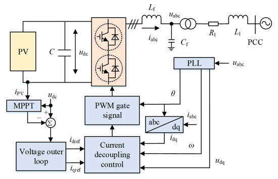
Figure 2.
The control structure of the grid-connected PV power generation system.
The main control parameters of the grid-connected PV inverter are shown in Table 1. The voltage regulator, as the outer-loop control, first controls the inverter DC-side output voltage value udc to track the given voltage value udcref, and then obtains the active current components reference value idref and the reactive current components reference value iqref through the proportion integration (PI) controller. Usually, the grid-connected PV power generation system operates in the unit power factor state, so iqref is taken as 0. The current regulator, as the inner-loop control, first takes the idref and iqref of the voltage outer-loop output as input signals, and then makes the difference with the inverter AC-side output current values id and iq and inputs them to the PI controller to realize the sinusoidal pulse width modulation (SPWM) modulated voltage wave by decoupling.

Table 1.
The main control parameters of the grid-connected PV inverter.
Through the dual-loop control and PWM, the inverter connected to the PV power plant and the regional power grid can realize the decoupling of the active power and reactive power. The power injected into the power grid by the PV power system can be expressed as Equation (1).
Taking the d-axis as the direction of the AC-side voltage synthesis vector, the voltage component in the q-axis direction is 0, i.e., Ugq = 0. The grid-connected PV power generation system usually operates in the unit power factor state, so iq = iqref = 0. Therefore, the above equation can be expressed as Equation (2):
where P and Q denote the active and reactive power emitted by the grid-connected PV power generation system, respectively; Ugd, Ugq and Id, Iq denote the d-q axis components of the grid-connected voltage and the current of the PV power generation system, respectively.
According to the above equation, the control of the active and reactive power of the grid-connected PV power generation system can be achieved by controlling the d-q axis components of the grid-connected current of the PV power generation system. In the millisecond power system transient process, the process of the electromechanical transient characteristics containing the dynamic load of the PV power generation system is extremely short, and the external dynamic characteristics of the PV power generation system depend on the grid-connected point voltage variation.
3. Dynamic Discrete Equivalent Model for the Grid-Connected PV Power Generation System
3.1. Single-Phase Equivalent Circuit Model
Because the inverter delivers power by injecting current into the power grid and controlling it, it can be equated to the current source. The power grid, on the other hand, is considered to maintain a constant voltage at a given moment, so it is equated to the voltage source. Based on this, the single-phase equivalent circuit model of the grid-connected PV power generation system is represented by the series combination of the controlled voltage source, equivalent resistance, and equivalent reactance; the specific structure is shown in Figure 3. In the figure, iPV denotes the output current of the PV array; udc denotes the DC side voltage of the inverter; idc denotes the current injected into the inverter; Ui denotes the AC side voltage of the inverter; R and L denote the equivalent resistance and reactance from the inverter to the grid-connected point, respectively; IL denotes the grid-connected current; Ug denotes the grid-connected voltage; and C denotes the voltage regulator capacitor on the DC side of the PV power generation system.
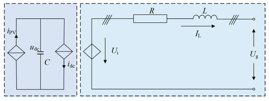
Figure 3.
The single-phase equivalent circuit model of the grid-connected PV power generation system.
The dynamic differential equation of the grid-connected PV power generation system can be obtained from Kirchhoff’s voltage and current law (KVL, KCL), as shown in Equation (3).
The third-order dynamic differential equation with the d-q axis components as state variables is obtained by subjecting Equation (3) to the Park transformation, as shown in Equation (4):
where IL.d, IL.q and Ug.d, Ug.q denote the d-q axis components of the grid-connected current and the voltage of the PV power generation system, respectively; Ui.d and Ui.q denote the d-q axis components of the AC side voltage of the inverter, respectively; Sd and Sq denote the d-q axis components of the switching vector in the synchronous coordinate system, respectively; and ω denotes the angular frequency of the grid-connected voltage.
The expression of the output power of the grid-connected PV power generation system represented by the real and imaginary components of the grid-connected current can be obtained by performing the Parker inverse transformation on Equation (4), as shown in Equation (5).
3.2. Dynamic Discrete Equivalent Model
Based on the derivation of the mathematical equation of the single-phase equivalent circuit model, the output power of the grid-connected PV power generation system can be controlled by the real and imaginary components of the grid-connected current. To accurately and reasonably describe the dynamic characteristics of the grid-connected PV power generation system, the dynamic discrete equivalent model of the grid-connected PV power generation system is established based on the single-phase equivalent circuit model, and the corresponding mathematical equations are derived as follows [30]:
The incremental form of the d-q axis components of the grid-connected current of the PV power generation system can be obtained by applying the Laplace transform to Equation (4) and linearizing it, as shown in Equation (6).
where:
- , , , , ;
- , , , , ;
- , , , , .
The load model in the frequency domain can be obtained by deforming the incremental form of Equation (6), as shown in Equation (7).
where:
, ,
, .
The expression of the relationship between the grid-connected voltage and the real and imaginary parts of the grid-connected current of the PV power generation system can be obtained by coordinating the transformation of Equation (7), as shown in Equation (8).
where:
,
,
,
.
Then, convert Equation (8) into the transfer function of the real and imaginary parts of the grid-connected current concerning the grid-connected voltage, as shown in Equation (9).
where:
,
;
,
;
,
.
The difference equation model with the real and imaginary components of the grid-connected current as outputs can be obtained by performing bilinear transformation on Equation (9), as shown in Equation (10):
where k denotes the sampling moment of the grid-connected PV power generation system and θα1–θα9 and θβ1–θβ9 denote the real and imaginary part coefficients of the differential equation model, respectively. The expressions are as follows:
, ,
, ,
, ,
, ,
; ,
, ,
, ,
, ,
, .
From Equation (10), it can be seen that the dynamic discrete equivalent model of the grid-connected PV power generation system needs to determine two sets of unknown parameters; namely, the current real and imaginary parts parameters, which are θα1, θα2, θα3, θα4, θα5, θα6, θα7, θα8, θα9 and θβ1, θβ2, θβ3, θβ4, θβ5, θβ6, θβ7, θβ8, θβ9.
4. Dynamic Discrete Equivalent Model Parameter Identification Method
4.1. Parameter Identification Objective Function
This paper establishes the dynamic discrete equivalent model of the real and imaginary parts of the grid-connected current of the PV power generation system, and to accurately identify the two sets of parameters in this model, the reasonable objective function needs to be designed to minimize the error between the output of the dynamic discrete equivalent model and actual system of the grid-connected transmission and distribution. In this paper, the root-mean-square error (RMSE) is chosen as the objective function, as shown in Equation (11):
where N denotes the number of sampling points of the actual system; E and Ê denote the RMSE of the real and imaginary currents of the grid-connected PV power generation system, respectively; Irk and Ijk denote the real and imaginary current values of the kth sampling point in the actual system, respectively; and Îrk and Îjk denote the real and imaginary current values of the kth sampling point in the dynamic discrete equivalence model, respectively.
4.2. OLS Parameter Identification
The OLS parameter identification is mainly according to the known input and output data to identify model parameters, and the parameter identification process includes two parts, data acquisition and parameter identification, as shown in Figure 4. Among them, h(k) and y(k) denote the input and output variables of the grid-connected PV power generation system, respectively; f(k) and f*(k) denote the actual output and model output of the grid-connected PV power generation system, respectively; e(k) denotes the noise variable; θ*(k) denotes the parameter to be identified; J′(k) denotes the error between the actual output and model output of the grid-connected PV power generation system. First, the voltage U, active power P, and reactive power Q at the PCC of the grid-connected PV power generation system model are obtained as the known conditions of Equation (10). Then, the real part coefficients θα1–θα9 and imaginary part coefficients θβ1–θβ9 of the dynamic discrete equivalent model are identified. Finally, the dynamic data of the real current Ir, imaginary current Ij, and bus voltage U at the PCC are chosen, and the minimum variance J is used as the target correction parameter estimate.
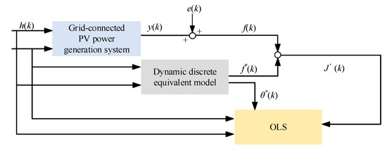
Figure 4.
The parameter identification process based on the OLS.
The corresponding nonlinear model equation is analyzed with m sets of observations, as shown in Equation (12); the variance of the system is obtained, as shown in Equation (13); and there exists a set of optimal parameter estimates, as shown in Equation (14):
where: x1 = ∆Ir(k + 3), x2 = ∆Ir(k + 2), x3 = ∆Ir(k + 1), x4 = ∆Ir(k), x5 = ∆U(k + 4), x6 = ∆U(k + 3), x7 = ∆U(k + 2), x8 = ∆U(k + 1), x9 = ∆U(k); x10 = ∆Ij(k + 3), x11 = ∆Ij(k + 2), x12 = ∆Ij(k + 1), x13 = ∆Ij(k), x14 = ∆U(k + 4), x15 = ∆U(k + 3), x16 = ∆U(k + 2), x17 = ∆U(k + 1), x18 = ∆U(k); y1 = ∆Ir(k + 4), y2 = ∆Ij(k + 4).
4.3. BA Parameter Identification
The BA mainly uses ultrasound to locate prey, and the predation process includes global searches and local searches. The global search updates pulse frequency fi, flight speed vi, and position xi by Equations (15)–(17) and pulse loudness Ai and pulse frequency Ri by Equations (18)–(19). The local search updates position xi by Equation (20):
where β denotes the arbitrary value within [0, 1]; x* denotes the optimal value in the global search; fmin and fmax denote the minimum and maximum values of the pulse frequency, respectively; α denotes the decay coefficient of the pulse loudness, taking values in the range of [0, 1]; γ denotes the enhancement coefficient of the pulse frequency, taking values greater than 0; and ε denotes the random number within [−1, 1].
The BA parameter identification means solving for the parameter values corresponding to the minimum RMSE of the objective function based on the same inputs and outputs of the given model and actual system. In essence, it is also a function optimization problem, and its adaptability is shown in Figure 5. The general framework of the parameter identification of the dynamic discrete equivalent model of the grid-connected PV power generation system based on the BA is shown in Table A1 of Appendix A, where rand denotes the uniform random number within [0, 1].
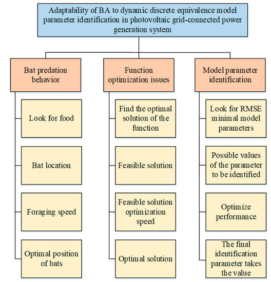
Figure 5.
The adaptability of the BA to the dynamic discrete equivalent model parameter identification of the grid-connected PV power generation system.
5. Analysis of Simulation Results
5.1. Simulation System Overview
To study the adaptability of the dynamic discrete equivalent model of the grid-connected PV power generation system, the simulation platform of the grid-connected power PV generation system is built in MATLAB/Simulink, as shown in Figure 6.In the figure, the transmission system is the IEEE14 node system and the distribution system is the PV power generation system; the main parameters of the transmission and distribution system are given in Table A2 of Appendix A. Node 7 is set as the grid-connected point, and the PV power generation system is connected to the IEEE14 node system from node 7.
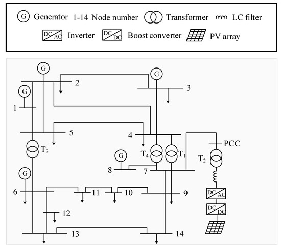
Figure 6.
The schematic diagram of the PV power generation system connected to the IEEE14 node system.
- (1)
- Simulation parameters setting
Simulation time t = 1 s, simulation step s = 0.001 s, sampling frequency f = 1000 Hz, three-phase short-circuit ground fault occurs at 0.5 s, and fault duration Δt = 0.05 s, using the discrete/ode45 solver. In addition, for the BA, fitness function fFitness = 1/E; population size sizepop = 20; the number of feature quantities sizeaim = 9; the maximum number of iterations maxiter = 1000; pulse frequency enhancement coefficient γ = 0.85; pulse frequency range [Rmin, Rmax] = [0, 1]; pulse loudness decay coefficient α = 0.1; pulse loudness range [Amin, Amax] = [0, 1]; and pulse frequency range [fmin, fmax] = [0, 2].
- (2)
- Simulation scenarios setting
In this study, the scenarios are formed by the combination of the PV penetration rate and the voltage dip depth. The PV penetration rate is controlled by changing the capacity of the PV connected to the IEEE14 node system, and the voltage dip depth is controlled by changing the fault resistance at the grid-connected bus. The single scenario is defined with the single PV penetration rate and voltage dip depth combination, and the multiple scenarios are defined with the multiple PV penetration rates and voltage dip depths combination.
Due to the page limitation, in the single scenario setting, the PV penetration rate is 48%, 56%, and 64%; the voltage dip depth is 5%, 15%, and 25%; the OLS and BA are used to identify the dynamic discrete equivalent model of the grid-connected PV power generation system, respectively; and the generalization ability of the parameters identified by the OLS and BA to the model is investigated. In the multiple scenarios setting, the PV penetration rate is increased from 10% to 80% (with a spacing of 8%); the voltage dip depth is increased from 5% to 50% (with a spacing of 5%); the OLS and BA are used to identify the dynamic discrete equivalent model of the grid-connected PV power generation system, respectively; a set of the general identification parameters is obtained; and the generalization ability of the general parameters identified by the OLS and BA to the model is investigated.
5.2. Simulation Verification in the Single Scenario
The PV penetration rate is set to 48%, 56%, and 64%; the voltage dip depth is 5%, 15%, and 25%; and the OLS and BA are used to identify the dynamic discrete equivalent model of the grid-connected PV power generation system, respectively; the fitting errors of the identified parameters to the model are shown in Table 2, Table 3 and Table 4. The PV penetration rates of 48%, 56%, and 64% and the voltage dip depth of 25% are chosen to investigate the generalization ability of the parameters identified by the OLS and BA to the model, as shown in Figure 7, Figure 8 and Figure 9. In the figures, Ir and Ij denote the measured values of the grid-connected PV power generation system and Ir-OLS, Ij-OLS and Ir-BA, Ij-BA denote the model values of the grid-connected PV power generation system using the OLS and BA parameter identification.

Table 2.
The fitting errors for the PV penetration rate of 48%.

Table 3.
The fitting errors for the PV penetration rate of 56%.

Table 4.
The fitting errors for the PV penetration rate of 64%.
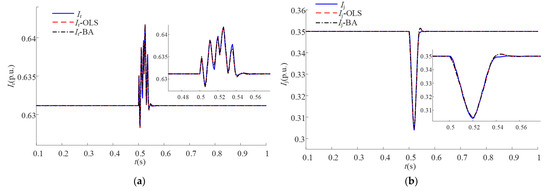
Figure 7.
The generalization ability with the PV penetration rate of 48%. (a) Current real part; (b) Current imaginary part.
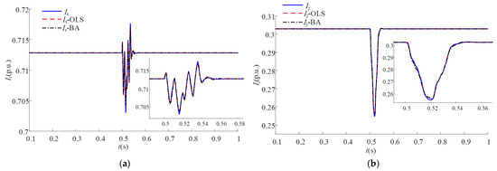
Figure 8.
The generalization ability with the PV penetration rate of 56%. (a) Current real part; (b) Current imaginary part.
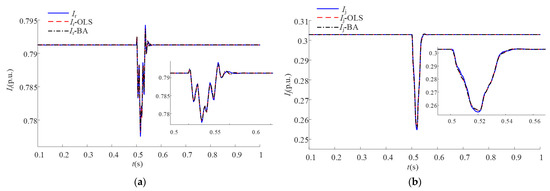
Figure 9.
The generalization ability with the PV penetration rate of 64%. (a) Current real part; (b) Current imaginary part.
From Table 2, Table 3 and Table 4, it can be seen that both the OLS and BA identify parameters with small fitting errors to the model in the single scenario, but the OLS is slightly better than the BA.
From Figure 5, Figure 6 and Figure 7, it can be seen that the parameters identified by the OLS and BA in the single scenario have better generalization ability to the model.
In summary, it is shown that the dynamic discrete equivalent model of the grid-connected PV power generation system proposed in this paper has good adaptability.
5.3. Simulation Verification in Multiple Scenarios
The PV penetration rate is increased from 10% to 80% (with spacing of 8%), the voltage dip depth is increased from 5% to 50% (with spacing of 5%), and the OLS and BA are used to identify the dynamic discrete equivalent model of the grid-connected PV power generation system, respectively; the generalization ability of a set of the general parameters to the model is shown in Figure 10 and Figure 11. In the figures, the X-axis denotes the voltage dip depth; the Y-axis denotes the PV penetration rate; the Z-axis denotes the fitting error; and the more yellow color indicates the larger fitting error, and the more blue color indicates the smaller fitting error.
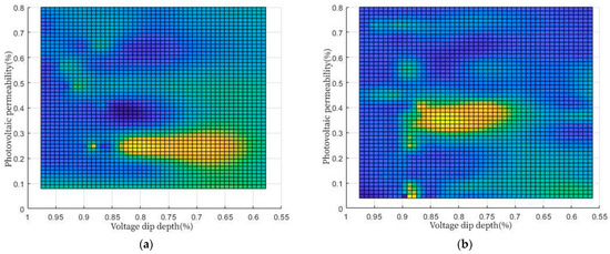
Figure 10.
The generalization ability of the OLS parameter identification. (a) Current real part; (b) Current imaginary part.
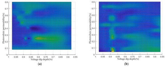
Figure 11.
The generalization ability of the BA parameter identification. (a) Current real part; (b) Current imaginary part.
From Figure 10 and Figure 11, it can be seen that when the PV penetration rate is in the range of 20–30% and the voltage dip depth is in the range of 15–40%, the BA has significantly better generalization ability than the OLS for the real part of the dynamic discrete equivalent model of the grid-connected PV power generation system; when the PV penetration rate is in the range of 30–40% and the voltage dip depth is in the range of 10–30%, the BA has significantly better generalization ability than the OLS for the imaginary part of the dynamic discrete equivalent model of the grid-connected PV power generation system.
In summary, the generalization ability of a set of the general parameters identified by the BA in the multiple scenarios is better than that of the OLS.
6. Conclusions
In this paper, based on the electromechanical transient characteristics of the grid-connected PV power generation system, the corresponding dynamic discrete equivalent model is established, and the simulation platform of the grid-connected PV power generation system is built in MATLAB/Simulink to study the adaptability of the dynamic discrete equivalent model of the grid-connected PV power generation system from the single and multiple scenarios using the OLS and BA while comparing the generalization ability of the parameters identified by the two methods to the model. Through the simulation experiments, it is found that the dynamic discrete equivalent model of the grid-connected PV power generation system proposed in this paper has good adaptability and can accurately reflect the dynamic characteristics of the grid-connected PV power generation system, and the parameters identified by the BA are more generalized than the OLS.
In this paper, the OLS and BA were selected for the parameter identification of the dynamic discrete equivalent model of the grid-connected PV power generation system without comparing the parameter identification effects of other intelligent algorithms. Therefore, in future research work, it is necessary to further analyze the parameter identification effects of the different intelligent algorithms based on the model proposed in this paper to ensure the generalizability of the model.
Author Contributions
Conceptualization, Y.M. and X.C.; methodology, Y.M.; software, Y.M.; validation, Y.M., X.C. and J.H.; formal analysis, Y.M. and X.C.; investigation, Y.M. and X.C.; resources, K.L. and M.D.; data curation, Y.M.; writing—original draft preparation, Y.M.; writing—review and editing, Y.M.; visualization, Y.M.; supervision, K.L.; project administration, M.D.; funding acquisition, M.D. All authors have read and agreed to the published version of the manuscript.
Funding
This research was funded by the Yunnan Provincial Education Department Scientific Research Fund Grant Project under Grant 2022J1279 and Yunnan Power Grid Limited Liability Company Science and Technology Project under Grant YNKJXM20180736.
Data Availability Statement
Data sharing is not applicable to this article.
Conflicts of Interest
The authors declare no conflict of interest.
Appendix A

Table A1.
The general framework for the parameter identification of the dynamic discrete equivalent model of the grid-connected PV power generation system based on the BA.
Table A1.
The general framework for the parameter identification of the dynamic discrete equivalent model of the grid-connected PV power generation system based on the BA.
| Steps | Project Content |
|---|---|
| 1 | Build the grid-connected PV power generation system model in MATLAB/Simulink. |
| 2 | Obtain the voltage U, active power P, and reactive power Q at the grid connection of the grid-connected PV power generation system model. |
| 3 | Initialize the population size n and the maximum number of iterations T. |
| 4 | Randomly initialize the position of each individual in the population. |
| 5 | Set t = 0. |
| 6 | WHILE t < T |
| 7 | Calculate the fitness of each individual according to Equations (10) and (11). |
| 8 | Determine the current optimal individual position of the population xbest(t). |
| 9 | Update individual pulse frequency fi, flight speed vi, and position xi according to Equations (15)–(17). |
| 10 | FOR1 i = 2, 3, …, n |
| 11 | IF1 rand > Ri |
| 12 | Update individual position xi according to Equation (17). |
| 13 | ELSE1 |
| 14 | Update individual position xi according to Equation (20). |
| 15 | END IF1 |
| 16 | END FOR1 |
| 17 | FOR2 i = 2, 3, …, n |
| 18 | IF2 rand < Ai |
| 19 | Update individual position xi, pulse loudness Ai, and pulse frequency Ri according to Equations (17)–(19). |
| 20 | ELSE2 |
| 21 | Update individual pulse frequency fi, flight speed vi, and position xi according to Equations (15)–(17). |
| 22 | END IF2 |
| 23 | END FOR2 |
| 24 | Calculate the fitness of each individual according to Equations (10) and (11). |
| 25 | Determine the current optimal individual position of the population xbest(t). |
| 26 | END WHILE |
| 27 | Output the optimal parameters of the dynamic discrete equivalent model of the grid-connected PV power generation system. |

Table A2.
The main parameters of the transmission and distribution system.
Table A2.
The main parameters of the transmission and distribution system.
| Serial Number | Parameter Name | Parameter Value |
|---|---|---|
| Transmission system (IEEE14 node system) | Reference voltage (Uref [kV]) | 23 |
| Standard frequency (fs [Hz]) | 50 | |
| Series inductor (Ls [H]) | 0.618 | |
| Series resistance (Rs [Ω]) | 0.4 | |
| Distribution system (PV power generation system) | Stand-alone capacity (Ps [kW]) | 500 |
| Rated voltage (Ur [V]) | 700 | |
| Filter inductors (Lf [mH]) | 0.17 | |
| Filter capacitors (Cf [F]) | 0.0018 | |
| Step-up transformer ratio (k [kV]) | 35/230 | |
| Open-circuit voltage (Uoc [V]) | 44.5 | |
| Short-circuit current (Isc [A]) | 8.2 | |
| Optimal operating voltage (Um [V]) | 35.5 | |
| Optimal operating current (Im/A) | 7.51 | |
| Number of consistencies (Ns [piece]) | 300 | |
| Number of parallels (Np [piece]) | 200 | |
| Components conversion efficiency (ηc [%]) | 16.9 |
References
- Mansouri, N.; Lashab, A.; Sera, D.; Guerrero, J.M.; Cherif, A. Large photovoltaic power plants integration: A review of challenges and solutions. Energies 2019, 12, 3798. [Google Scholar] [CrossRef]
- Shair, J.; Li, H.Z.; Hu, J.B.; Xie, X.R. Power system stability issues, classifications and research prospects in the context of high-penetration of renewables and power electronics. Renew. Sustain. Energy Rev. 2021, 145, 111111. [Google Scholar] [CrossRef]
- Yoro, K.O.; Daramola, M.O.; Sekoai, P.T.; Wilson, U.N.; Eterigho-lkelegbe, O. Update on current approaches, challenges, and prospects of modeling and simulation in renewable and sustainable energy systems. Renew. Sustain. Energy Rev. 2021, 150, 111506. [Google Scholar] [CrossRef]
- Shafiullah, M.; Ahmed, S.D.; Al-Sulaiman, F.A. Grid Integration Challenges and Solution Strategies for Solar PV Systems: A Review. IEEE Access 2022, 10, 52233–52257. [Google Scholar] [CrossRef]
- Refaat, S.S.; Abu-Rub, H.; Sanfilippo, A.P.; Mohamed, A. Impact of grid-tied large-scale photovoltaic system on dynamic voltage stability of electric power grids. IET Renew. Power Gener. 2018, 12, 157–164. [Google Scholar] [CrossRef]
- Taul, M.G.; Wang, X.F.; Davari, P.; Blaabjerg, F. An overview of assessment methods for synchronization stability of grid-connected converters under severe symmetrical grid faults. IEEE Trans. Power Electron. 2019, 34, 9655–9670. [Google Scholar] [CrossRef]
- Molina, M.G.; Espejo, E.J. Modeling and simulation of grid-connected photovoltaic energy conversion systems. Int. J. Hydrog. Energy 2014, 39, 8702–8707. [Google Scholar] [CrossRef]
- Fiedler, T. Simulation of a power system with large renewable penetration. Renew. Energy 2019, 130, 319–328. [Google Scholar] [CrossRef]
- Jeffrey Kuo, C.F.; Lee, Y.W.; Umar, M.L.; Yang, P.C. Dynamic modeling, practical verification and energy benefit analysis of a photovoltaic and thermal composite module system. Energy Convers. Manag. 2017, 154, 470–481. [Google Scholar] [CrossRef]
- Lee, Y.W.; Jeffrey Kuo, C.F.; Weng, W.H.; Huang, C.Y.; Peng, C.Y. Dynamic modeling and entity validation of a photovoltaic system. Appl. Energy 2017, 200, 370–382. [Google Scholar] [CrossRef]
- Mai, X.H.; Kwak, S.K.; Jung, J.H.; Kim, K.A. Comprehensive Electric-Thermal Photovoltaic Modeling for Power-Hardware-in-the-Loop Simulation (PHILS) Applications. IEEE Trans. Ind. Electron. 2017, 64, 6255–6264. [Google Scholar] [CrossRef]
- Gao, Y.; Dong, J.F.; Isabella, O.; Santbergen, R.; Tan, H.; Zeman, M.; Zhang, G.Q. Modeling and analyses of energy performances of photovoltaic greenhouses with sun-tracking functionality. Appl. Energy 2019, 233-234, 424–442. [Google Scholar] [CrossRef]
- Salimi, M.; Radmand, F.; Firouz, M.H. Dynamic modeling and closed-loop control of hybrid grid-connected renewable energy system with multi-input multi-output controller. J. Mod. Power Syst. Clean Energy 2021, 9, 94–103. [Google Scholar] [CrossRef]
- Zhang, M.; Miao, Z.X.; Fan, L.L. Reduced-order analytical models of grid-connected solar photovoltaic systems for low-frequency oscillation analysis. IEEE Trans. Sustain. Energy 2021, 12, 1662–1671. [Google Scholar] [CrossRef]
- Mahmud, M.R.; Abdou, A.F.; Pota, H. Stability analysis of grid -connected photovoltaic systems with dynamic phasor model. Electronics 2019, 8, 747. [Google Scholar] [CrossRef]
- Bouali, C.; Schulte, H.; Mami, A. A High Performance Optimizing Method for Modeling Photovoltaic Cells and Modules Array Based on Discrete Symbiosis Organism Search. Energies 2019, 12, 2246. [Google Scholar] [CrossRef]
- Almeida, P.M.; Barbosa, P.G.; Duarte, J.L.; Ribeiro, P.F. Comprehensive synchronous reference frame discrete-time modelling of a grid-connected PV for fast DC-side voltage control. Electr. Power Syst. Res. 2017, 150, 162–168. [Google Scholar] [CrossRef]
- Soetedjo, A.; Sulistiawati, I.B. Implementing Discrete Model of Photovoltaic System on the Embedded Platform for Real-Time Simulation. Energies 2020, 13, 4447. [Google Scholar] [CrossRef]
- Li, P.X.; Gu, W.; Wang, L.F.; Xu, B.; Wu, M.; Shen, W.X. Dynamic equivalent modeling of two-staged photovoltaic power station clusters based on dynamic affinity propagation clustering algorithm. Int. J. Electr. Power Energy Syst. 2018, 95, 463–475. [Google Scholar] [CrossRef]
- Salazar-Chiralt, R.; Cheah-Mane, M.; Mateu-Barriendos, E.; Bullich-Massague, E.; Prieto-Araujo, E.; Mehrjerdi, H.; Gomis-Bellmunt, O. Dynamic interactions in large scale photovoltaic power plants with frequency and voltage support. Electr. Power Syst. Res. 2022, 207, 107848. [Google Scholar] [CrossRef]
- Sanchez, J.H.; Castro, L.M. Advanced three-stage photovoltaic system phasor model for grid integration dynamic studies. Sol. Energy 2022, 235, 82–93. [Google Scholar] [CrossRef]
- Ramirez, A. Frequency Domain Modeling of Photovoltaic Systems for Transient Analysis. IEEE Trans. Power Deliv. 2022, 37, 3762–3770. [Google Scholar] [CrossRef]
- Shen, F.; Zhang, Y.T.; Qiu, G.F.; Yang, Z.W.; Li, S.W.; Yang, G.B. Generalized discrete-time equivalent model for interfacing the grid-connected photovoltaic system. IET Gener. Transm. Distrib. 2023, 17, 1070–1080. [Google Scholar] [CrossRef]
- Long, H.; Xu, S.H.; Lu, X.; Yang, Z.J.; Li, C.; Jing, J.P.; Wu, Z. Data-Driven Hybrid Equivalent Dynamic Modeling of Multiple Photovoltaic Power Stations Based on Ensemble Gated Recurrent Unit. Front. Energy Res. 2020, 8, 185. [Google Scholar] [CrossRef]
- Elkholy, A.; Abou El-Ela, A.A. Optimal parameters estimation and modelling of photovoltaic modules using analytical method. Heliyon 2019, 5, e02137. [Google Scholar] [CrossRef] [PubMed]
- Xu, Y.; Jin, W.J. A parameter identification model for the Photovoltaic grid-connected inverter. Optik 2017, 142, 23–32. [Google Scholar] [CrossRef]
- Long, W.; Jiao, J.J.; Liang, X.M.; Xu, M.; Tang, M.Z.; Cai, S.H. Parameters estimation of photovoltaic models using a novel hybrid seagull optimization algorithm. Energy 2022, 249, 123760. [Google Scholar] [CrossRef]
- Abdel-Basset, M.; El-Shahat, D.; Chakrabortty, R.K.; Ryan, M. Parameter estimation of photovoltaic models using an improved marine predators algorithm. Energy Convers. Manag. 2021, 227, 113491. [Google Scholar] [CrossRef]
- Pires Deotti, L.M.; Rezende Pereira, J.L.; da Silva Junior, I.C. Parameter extraction of photovoltaic models using an enhanced Lévy flight bat algorithm. Energy Convers. Manag. 2020, 221, 113114. [Google Scholar] [CrossRef]
- Liu, K.; Chen, X.; Chen, L.; Lin, Z.; Shen, F. Dynamic discrete equivalent model of photovoltaic power generation system. J. Shanghai Jiaotong Univ. 2022, 57, 412–421 Available online:. [Google Scholar] [CrossRef]
Disclaimer/Publisher’s Note: The statements, opinions and data contained in all publications are solely those of the individual author(s) and contributor(s) and not of MDPI and/or the editor(s). MDPI and/or the editor(s) disclaim responsibility for any injury to people or property resulting from any ideas, methods, instructions or products referred to in the content. |
© 2023 by the authors. Licensee MDPI, Basel, Switzerland. This article is an open access article distributed under the terms and conditions of the Creative Commons Attribution (CC BY) license (https://creativecommons.org/licenses/by/4.0/).