Article

Evaluation of Mechanical Properties and HPM Pulse Shielding Effectiveness of Cement-Based Composites

1
Faculty of Civil Engineering, Wroclaw University of Science and Technology, Wybrzeże Wyspiańskiego 27, 50-370 Wrocław, Poland
2
Department of Civil and Environmental Engineering, Massachusetts Institute of Technology, 77 Massachusetts Avenue, Cambridge, MA 02139, USA
*
Author to whom correspondence should be addressed.
Energies 2023, 16(10), 4062; https://doi.org/10.3390/en16104062
Submission received: 15 March 2023 / Revised: 5 May 2023 / Accepted: 11 May 2023 / Published: 12 May 2023

Abstract

:
In today’s world, protection against electromagnetic waves, including high-power microwave (HPM) pulses, is becoming increasingly important. Hence, the aim of this research was to select an absorbing admixture, which, when used in an appropriate quantity, improves the effectiveness of shielding against electromagnetic waves and, at the same time, satisfies the requirements that are important from a construction engineering point of view. Altogether, eighteen admixtures (including two types of fibers), added in different quantities, and three types of aggregate have been tested. The compressive and flexural strength test results show that the greatest improvement in the tested mechanical properties was achieved in the case of admixtures such as steel fibers, carbon black P803, ferrite, and fly ash. Regarding the effect of the admixtures on shielding effectiveness, the best results were obtained for graphite in the form of flakes, graphite in the form of powder, carbon black N990 and P803, polypropylene and steel fibers, and hybrid admixtures, i.e., ashporite aggregate with carbon black and ashporite aggregate with graphite flakes. Regarding both mechanical properties and HPM pulse shielding effectiveness, the best effects were achieved in the case of the specimens with a high steel fiber content.

1. Introduction

Today, cyber security is an increasingly critical issue. One way of destroying computer and telecommunications hardware and systems consists of using electromagnetic waves, including high-power microwave (HPM) pulses. As a kind of modern weapon that can damage electronic circuits, HPM pulses are characterized by the following parameters [1]: a high pulse power, a very short pulse duration, and a pulse propagation velocity equal to the speed of light. The pulsed HPM technology, with regards to both sources of HPM pulses and the ways of protecting against the latter, has been developed worldwide for over 20 years [2]. Ways of protecting buildings against HPM impulses should cover the shielding of rooms, space dividers and openings, and the absorption of radiation by space dividers and their components [3,4,5]. One of the many ways of improving the absorption properties of building materials consists of dispersing suitable particles [6], fibers [7], or meshes conducting electric current or having magnetic properties in the basic material (e.g., a cement composite [8,9]), as shown in Figure 1 [10,11,12].
There are several materials that can be used as microwave radiation-absorbing admixtures [13] to modify basic building materials, as described in detail by the authors of [14,15]. Among them, there are carbon-based materials, such as graphite [16], coke, carbon fibers, carbon nanotubes [17], graphene [18,19], fly ash [20,21], and carbon black [22]. In the latter study, a graphite admixture that accounted for to 17.5% of the high-alumina cement paste volume was found to improve electromagnetic shielding effectiveness. In [23], it was shown that, as the coke content by volume in a cement composite was increased (from 0.5% to 9.2%), the effectiveness of shielding against electromagnetic pulses increased for the frequency of 1.0 GHz and 1.5 GHz.
Figure 1. Models of composites with admixtures of: (a) particles, (b) fibers, and (c) meshes, or with a layered structure (d), exhibiting enhanced microwave absorption properties.
Energies 16 04062 g001
Other admixtures contributing to increased protection against microwave radiation are carbon fibers or threads, as demonstrated in [24,25], respectively. Owing to their unique properties, such as a large specific surface, slenderness, and low density at high-strength parameters, carbon nanotubes are also considered as a shielding effectiveness-enhancing admixture because their presence improves electrical conductance, as demonstrated in [26]. One should emphasize the importance of graphene since the latter can be used in the manufacture of cladding, increasing protection against microwave radiation, as demonstrated in i.a. [27].
One should also mention fly ash (a by-product of coal combustion), which is widely used as a supplementary cement material and can be successfully employed to increase electromagnetic shielding effectiveness [28]. Among carbon-based materials, carbon black is also considered a potential admixture, considering that it significantly improves (when used in the amount of up to 30% by wt.) the shielding properties of absorptive panels in a wide range of frequencies, i.e., from 8 GHz to 18 GHz [29].
Another material that is promising with regard to microwave radiation absorption effectiveness is nickel [30]. It was shown in [31] that, owing to this material’s high magnetic transformation temperature, a stable electromagnetic wave absorption capacity is achieved. Additionally, worth noting are iron powders, which were shown to be suitable for absorbing composites by the authors of [32]. The effect of the use of carbonyl iron combined with carbon black on electromagnetic wave absorption capacity in the frequency range of 2–18 GHz was examined in [33]. It was shown that the band of effective absorption changes with the quantity of the materials added. One should also mention ferrites, i.e., ceramic semiconductor materials exhibiting ferromagnetic properties. When used as admixtures in the manufacture of absorption elements, ferrites can provide protection against electromagnetic interference, which is discussed in [34,35,36]. Additionally, the authors of [37] showed that a composite containing a cement paste matrix made with the addition of a Mn-Zn ferrite had good microwave radiation absorption properties. Magnetites behave similarly to ferrites, but their advantage is that they naturally occur in the Earth’s crust; thus, they are relatively cheap. Their usefulness for electromagnetic radiation shielding in the case of cement composites was studied in [38]. It was found that, as a result using a magnetite that was up to 20% by the weight of the cement, the dielectric and magnetic losses in the frequency range of 2.6–3.9 GHz increased; therefore, the composite’s absorption properties improved.
The microwave radiation absorbing admixtures presented above can be used in the manufacture of composites used as building materials, provided that the requirements concerning the physical and mechanical characteristics are met. It should be noted that some of the above-mentioned admixtures not only have a positive effect on electromagnetic wave shielding but also contribute to an improvement in the mechanical properties of the composites containing the admixtures. In [39], it was demonstrated that a carbon fiber admixture amounting to 0.5% by the weight of the cement increases the flexural strength of the mortars thanks to reduced porosity. In [40], it was confirmed that the compressive strength of composites containing 0.1% carbon nanotubes by the weight of the cement is about 16.8% higher than that of the reference specimens. A summary of the research on the positive effect of the use of graphene on the properties of cement composites was presented in [41], wherein it was found that a graphene admixture reduces porosity and improves the distribution of micro-scale pores, thereby extending the life of the composite as well as increasing the latter’s compressive strength. Another admixture used as a partial substitute for cement in the making of mortars and concrete that has already been widely described in the literature is fly ash. The benefits that can be derived from the use of fly ash are summarized in [42]. These benefits include: reduced CO2 emission, improved workability, reduced heat of hydration and thermal cracking in concrete during the early setting period, and improved mechanical properties. It is also worth noting that nickel can be used in the production of cement, and the road concrete made using this cement has suitable properties, as reported by Wu et al. [43]. Additionally, ironsand is of interest to researchers as an ironsand admixture has a positive effect on the compressive and flexural strength of cement mortars, as shown in [44]. In [45], it was demonstrated that magnetite used as an aggregate in protective concretes subjected to high temperatures (>300 °C) improved their mechanical properties in comparison to river sand-based concretes.
So far, mechanical strength and shielding against electromagnetic pulses have not been jointly investigated. Therefore, it seems reasonable to select and optimize such an admixture which would improve electromagnetic wave shielding effectiveness and, at the same time, ensure that the requirements concerning the mechanical and economic properties of cement-based construction composites are met. This idea is presented graphically in Figure 2.
A composite similar to this could successfully perform the function of a building absorber, providing effective protection against the destructive action of HPM pulses and, at the same time, making it possible to easily shape the building structure.
Taking into consideration the above, the aim of this research was to evaluate composites modified with admixtures absorbing radio-frequency electromagnetic waves with regard to mechanical properties and HPM pulse-damping effectiveness. As well as absorbing additions, various aggregates, such as quartz, ashporite, and barite aggregates, were used in the experiments. This paper presents the results of compressive and flexural strength tests and measurements of electromagnetic properties, particularly electromagnetic wave absorption and damping. The results show that the requirements regarding the parameters critical for the proper protection of buildings against the action of HPM beam weapons can be met.

2. Significance of This Research

The threat posed by modern weapons in the form of HPM (high-power microwaves) can have a huge influence on today’s society. Although such weapons have no direct impact on human life (non-lethal weapons), their use can lead to the damage or destruction of electronic equipment, computer devices, and telecommunications systems, both military and civilian. Therefore, the indirect impact of HPM on the functioning of civilization can be extremely important. For this reason, there is a need to protect all sensitive electronic devices supporting key state institutions, servers, databases, etc. Depending on the size of the protected objects against HPM, protection can be implemented in various ways. One of these ways may be a building object (building or shelter) designed with the use of building materials that absorb HPM impulses. The structural elements of such a building, both small (hollow bricks, blocks) and large (monolithic walls, beams, columns), must meet the basic requirements for mechanical properties (compressive strength, bending, etc.) while ensuring an appropriate level of shielding effectiveness. Hence, there is a need to conduct research in the field of building materials absorbing HPM. As is known, a slight modification in the composition of cement or concrete mortar can have a huge impact on the mechanical properties of the structural element made of it. Therefore, experimental tests may be extremely important and useful for civil engineers, based on which it will be possible to demonstrate the improvement or deterioration of the mechanical properties of various modified concrete mixes. The results of such research can be useful both in the scientific field and in industry.
This research was conducted to answer the important scientific question: can a system of protecting buildings against the destructive action of HPM pulses be based on the use of cement composites containing admixtures that increase electromagnetic radiation shielding capability? The selected admixtures provided a basis for making simple building absorbers in the form of: bricks, hollow masonry units, concrete blocks, concrete, and cement mortar, which were used to both meet the construction requirements and ensure the highest possible degree of HPM pulse-damping effectiveness.

3. Materials and Mix Proportions

The used components with their available properties are presented in Table 1.
All of the specifications of the materials were guaranteed by the manufacturers. In total, six types of cement paste (presented in Table 2) were made from the above components. The cement pastes were used to make twenty-three series of cement mortars, designated as S0 to S22, whose compositions are presented in Table 3.
The admixtures, denoted as S1 to S7, S9 to S13, and S17 to S18 in Table 3, in the amount of 1%, 3%, and 10% by the weight of the cement, respectively, were used to make cement paste type I in accordance with the standard mortar design (Table 2 column 1). Multifaceted carbon nanotubes (Table 3, S8) in the amount of 0.5% and 1% by the weight of the cement, respectively, were added to cement paste type II made in accordance with the design given in Table 2. The air-entraining admixture Sika PRO3 (Table 3, S19), in the amount of 5% by the weight of the cement, and admixtures in the form of carbon black and graphite flakes (Table 3, S15, S16), in the amount of 10% by the weight of the cement, were added to cement paste III based on ashporite aggregate (Table 2). In the case of cement paste IV, conventional aggregate was replaced with barite aggregate so that the aggregate volumes were equivalent. Short (6 mm) steel fibers and long (50 mm) steel fibers, each in the amount of 250 g corresponding to 7.15% of the cement paste volume (Table 3, S21), were added to cement paste type V (Table 2). Short (10 mm) polypropylene fibers and long (45 mm) propylene fibers, each in the amount of 30 g corresponding to 5.45% of the cement paste volume (Table 3, S22), were added to cement paste type VI (Table 2).
The components of each of the mortars were homogenized in three steps. First, cement with the selected admixture was mixed in a mechanical mixer for 60 s. Then, water was added, aggregate was batched for 30 s, and the whole was mixed for the next 90 s. Finally, the components deposited on the pan’s walls were manually mixed, and the whole was mechanically mixed for 60 s.
It should be mentioned that, in the case of multifaceted carbon nanotubes, they were batched in the form of a suspension because of their tendency to form conglomerates. For this purpose, an mCNT suspension in demineralized water was prepared. The mCNT concentration amounted to 100 mg/L. Then, amphiphilic salts SRK-8 or 2T-70, in the amount corresponding to the mCNT/salt ratio of 1:10 and 1:20, were weighed into each of the bottles.
An mCNT suspension in water with no quaternary salt addition was used as the reference. The samples were not mechanically stirred but manually shaken and subjected to sonification in a water bath for 2 h. After sonification and 24 h after the latter, the suspension was subjected to sensory analysis. The best effect, i.e., a uniform distribution of nanotubes in the suspension (as evidenced by, i.a., the most intensive coloring of the suspension), was obtained in the case of the mCNT suspension in water with the amphiphilic salts SRK-8 addition for the salts concentration at the weight ratio of 1:10, as shown in Figure 3 and Figure 4 (based on report [47]), respectively.
Table 3. Compositions of designed cement mortars.
SeriesSymbolAdmixture0.5%
[g]
1%
[g]
3%
[g]
5%
[g]
10%
[g]
36%
[g]
Cement Paste Type
S0MStandard mortar------I
S1FAFly ash-5.416.2-54.0-I
S2FGGraphite in form of FG597 flakes-5.416.2-54.0-I
S3MGGraphite in form of MG1596 powder-5.416.2-54.0-I
S4CB1Carbon black Reoil RCB_615-5.416.2-54.0-I
S5CB2Carbon black N772-5.416.2-54.0-I
S6CB3Carbon black N990-5.416.2-54.0-I
S7CB4Carbon black P803-5.416.2-54.0-I
S8CNMultifaceted carbon nanotubes2.75.4----II
S9NiNickel (Ni) nanopowder 30–70 nm-5.416.2-54.0-I
S10NiONickel monoxide (NiO)
nanopowder 20–30 nm
-5.416.2-54.0-I
S11FFFiller FF + ferrite-5.416.2-54.0-I
S12CICarbonyl iron-5.416.2-54.0194.4I
S13FFerrite FMS 0.05-5.416.2-54.0-I
S14FAAAshporite aggregate------III
S15FAA + CB4Ashporite aggregate + P803----54.0-III
S16FAA + FGAshporite aggregate + FG597----54.0-III
S17Ni2O3Nickel oxide Ni2O3-5.416.2-54.0-I
S18CIMCarbonyl iron modified with SiO2-5.416.2-54.0-I
S19AIRAir-entraining admixture Sika PRO3---27.0--III
SeriesSymbolAdmixture6%
[g]
7.4%
[g]
Cement paste type
S20BABarite aggregate--IV
S21SFSteel fibers-500V
S22PFPolypropylene fibers60-VI
Figure 3. Carbon nanotube suspensions in (a) water with amphiphilic salts SRK-8 at concentrations of (b) 1:10 and (c) 1:20, and with amphiphilic salts 2T-70 at concentrations of (d) 1:10 and (e) 1:20 after sonification in water bath.
Energies 16 04062 g003
Figure 4. Carbon nanotubes (CN) suspensions in (a) water with amphiphilic salts SRK-8 at concentrations of (b) 1:10 and (c) 1:20, and with amphiphilic salts 2T-70 at concentrations of (d) 1:10 and (e) 1:20 24 h after sonification.
Energies 16 04062 g004
Herein, in this paper, numerical values indicating the admixture percentage content are added to the names of the series (e.g., FA_1 denotes a series with a fly ash admixture amounting to 1% of the weight of the cement).

4. Specimen Preparation and Test Methods

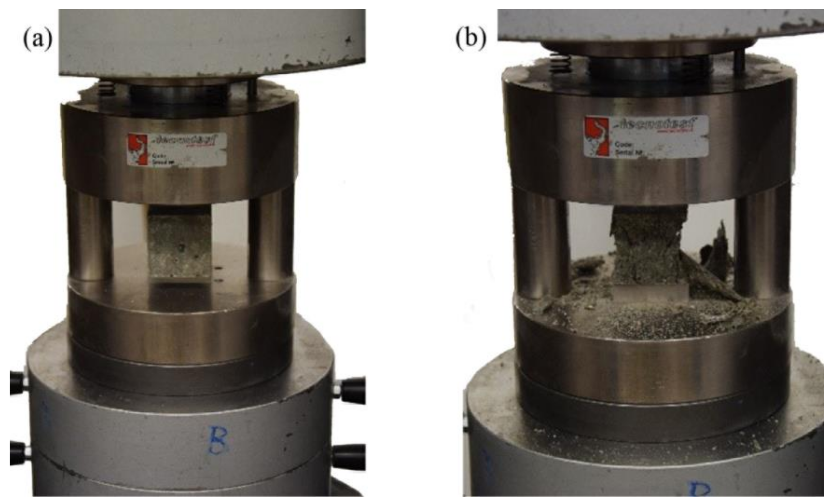
4.1. Mechanical Properties

Experimental tests to determine the compressive and bending strength of the tested samples were carried out in accordance with standard [46]. Bars of 40 mm × 40 mm × 160 mm were prepared for flexural (three-point bending) tests and compressive tests. After the flexural strength was determined, halves of the bars were used in compressive strength tests.
After the first layer of mortar was placed, it was consolidated with 60 jolts of a jolting table, and then a second layer of mortar with a surplus was put on. The excess mortar was spread using a small spatula and consolidated with another 60 jolts. The molded specimens were stored on a grid over water in a climatic chamber for 24 h. Then, they were demolded and cured in water at a temperature of 20 °C (±1 °C) until testing.
Flexural tests were carried out after 28 days of specimen curing. The specimens were dried with a paper towel and placed in a testing machine in a such a way that the floated surface was turned by 90° relative to the direction of load transmission. Each specimen was placed on support rollers so that its longitudinal axis was perpendicular to the support rollers. The specimens were loaded at a constant loading rate of 50 N/s (±10 N/s) until failure (breakage). The test stand and an exemplary mechanism of failure through flexure are shown in Figure 5.
Compressive strength tests were carried out on the halves of specimens (bars) that remained after the flexural test. After ascertaining that the bars’ halves were undamaged, they were placed with their side down in the middle of a 40 mm × 40 mm pressure plate (with an accuracy of ±0.5 mm) in the longitudinal direction so that their front faces protruded about 20 mm beyond the testing machine’s plates. During the test, the load was increased at a uniform rate of 2400 N/s (±200 N/s) until failure. The test stand and an exemplary failure due to compression are shown in Figure 6.
Figure 5. Specimen during flexural test before (a) and after failure (b).
Energies 16 04062 g005
Figure 6. Specimen during compression before (a) and after failure (b).
Energies 16 04062 g006

4.2. Shielding Effectiveness Testing

The main purpose of measuring the shielding effectiveness is to test the shielding properties of the electromagnetic wave using the material (test sample). The shielding effectiveness consists of two physical properties of the medium: wave reflection and wave absorption. The reflection of the electromagnetic wave from the tested material takes place when the wave reaches the boundary between centers with different electric permittivities. Then, the electromagnetic wave is partially (or completely) reflected analogically to visible light. Electromagnetic wave absorption, on the other hand, consists of the absorption of waves by the tested material. In this instance, the radiation reaching the material increases the energy of the material particles, which translates into an increase in the temperature of the shielding barrier.
Testing the shielding effectiveness requires proper planning of the experiment and preparation of the measuring stand, which should be isolated from electromagnetic interference coming from the outside. In this study, shielding effectiveness tests were carried out on a measuring stand equipped with a signal generator, antennas, network analyzer, and a measuring adapter conforming to the ASTM D4935-10 recommendation [48]. The stand was additionally equipped with elements for specimen mounting (Figure 7). After the proper calibration of the measuring stand, a sample of the tested material was placed in a specially prepared measuring window of the device, which is located between two chambers—one for the transmitting part and the other for the receiving part (Figure 7). The specimens for testing the effectiveness of shielding were prefabricated by forming the tested material in a mold as a segment of a coaxial line with an inner tube diameter of 33 mm, an outer diameter of 76 mm, and a nominal height of 30 mm. The inner and outer dimensions matched the measuring adapter and conform to the ASTM D4935-10 [48] recommendation. The specimen had the shape of a ring, filling the free space in the measuring adapter. Prefabrication ensured good electric contact between the tested specimen and the adapter walls. The adapter used for testing the shielding effectiveness is shown in Figure 8.
Thanks to this setup, it was possible to directly measure the effectiveness of plane wave shielding effectiveness of the materials placed in the mount. The measuring adapter consists of two coaxial line segments capped with a flange and an additional 30 mm long coaxial line segment containing the tested specimen. The measurements were made using a network analyzer that allows one to read the signal value in dBm, thanks to which it was possible to obtain the shielding effectiveness expressed in dB. Then, the shielding effectiveness is determined as a difference in damping levels between the reference specimen and the tested specimen.

5. Test Results and Their Analysis

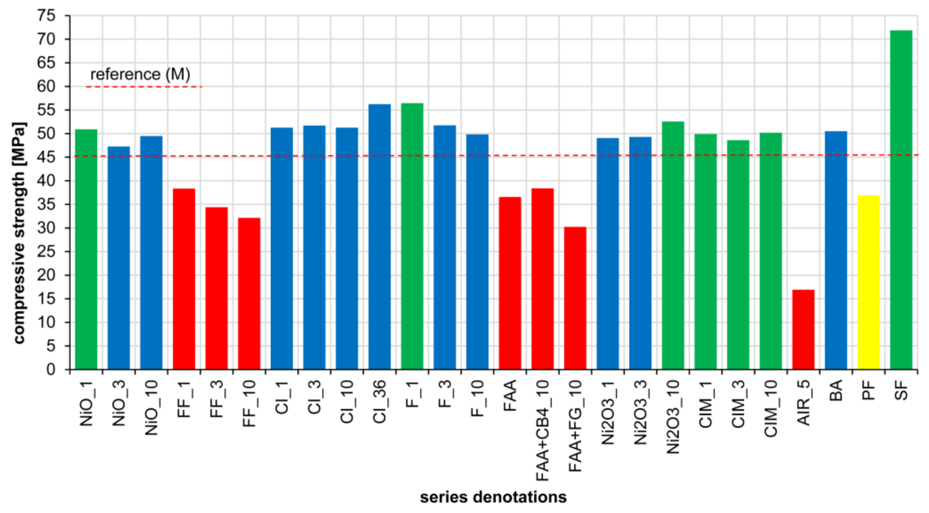
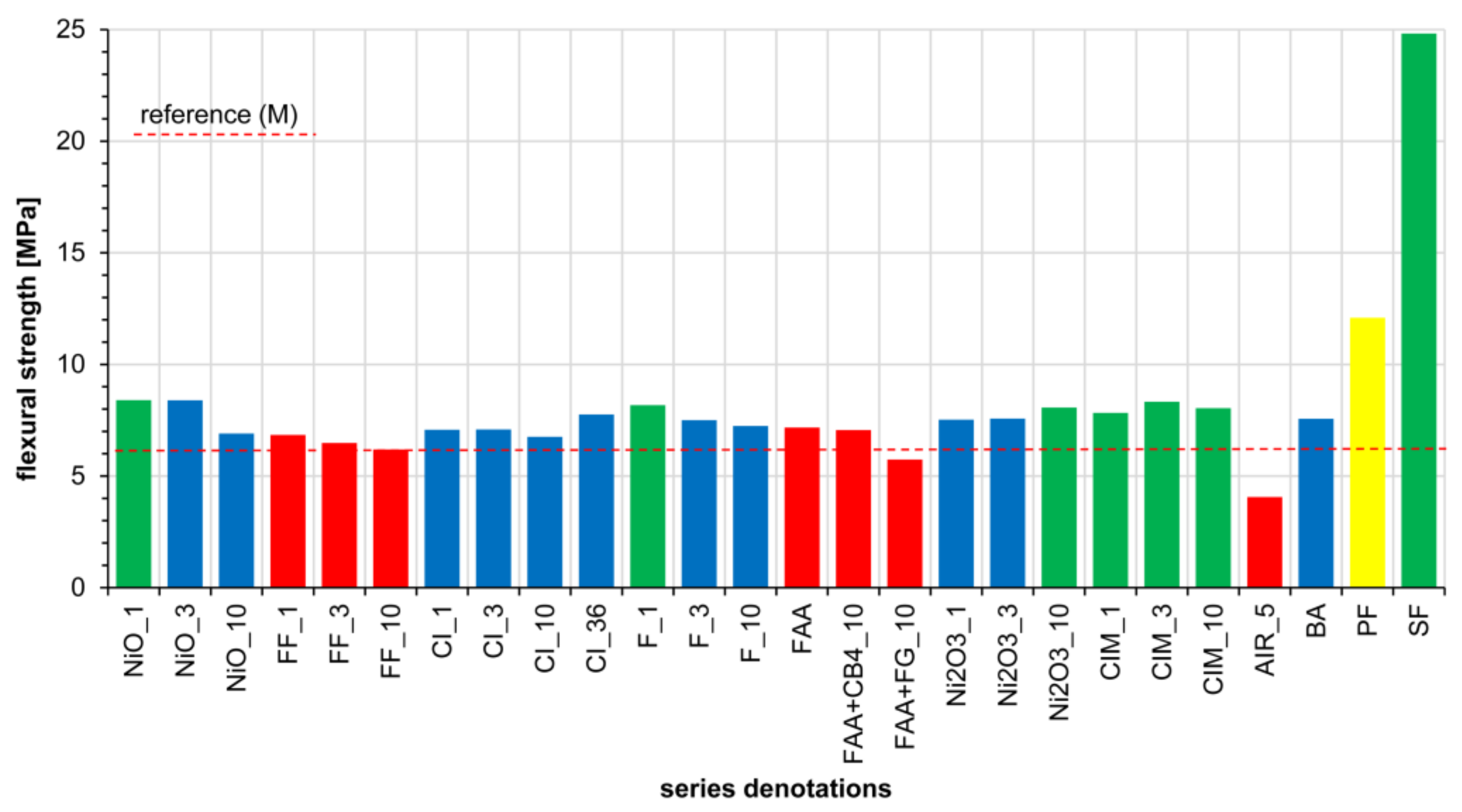
5.1. Mechanical Properties

Mean compressive strength fc and mean three-point flexural strength ftb were determined on the basis of the tests of the specimens’ mechanical properties according to [46]. The test results are presented in Table 4 and in Figure 9, Figure 10, Figure 11 and Figure 12. The results indicate a varied effect of the proposed admixtures relative to the reference specimen (standard mortar M). For the analysis of the results, the tested mortar series were grouped depending on the achieved effect:
  • specimens Af (green—Figure 9, Figure 10, Figure 11 and Figure 12): exhibiting increased both fc and ftb relative to reference mortar M: FA_1, FA_3, FA_10, FG_1, FG_3, MG_1, CB1_1, CB2_1, CB3_3, CB4_1, CB4_3, CB4_10, NiO_1, F_1, Ni2O3_10, CIM_1, CIM_3, CIM_10, SF;
  • specimens Bf (blue—Figure 9, Figure 10, Figure 11 and Figure 12): exhibiting increased fc at decreased ftb relative to reference mortar M: CB1_3, CB2_3, CB2_10, CB3_1, NiO_3, NiO_10, CI_1, CI_3, CI_10, CI_36, F_3, F_10, Ni2O3_1, Ni2O3_3, BA;
  • specimens Cf (red—Figure 9, Figure 10, Figure 11 and Figure 12): exhibiting decreased both fc and ftb relative to reference mortar M: FG_10, MG_3, MG_10, CB1_10, CB3_10, CN_0.5, CN_1, Ni_1, Ni_3, FF_1, FF_3, FF_10, FAA, FAA + CB4_10, FAA + FG_10, AIR_5.
Table 4. Compressive and flexural strength test results.
No.Specimenfc [MPa]ftb [MPa]No.Specimenfc [MPa]ftb [MPa]
1M48.067.8827NiO_150.908.40
2FA_150.748.0328NiO_347.258.39
3FA_355.057.9729NiO_1049.476.90
4FA_1054.688.6030FF_138.346.84
5FG_150.578.1831FF_334.386.48
6FG_349.448.6432FF_1032.146.19
7FG_1043.667.4933CI_151.257.07
8MG_151.328.5134CI_351.697.08
9MG_345.817.0735CI_1051.246.75
10MG_1038.277.3336CI_3656.237.75
11CB1_155.728.0937F_156.458.17
12CB1_353.287.4138F_351.737.50
13CB1_1047.646.3639F_1049.807.24
14CB2_153.618.2640FAA36.577.17
15CB2_348.887.1441FAA + CB4_1038.387.06
16CB2_1051.197.5142FAA + FG_1030.235.74
17CB3_152.197.7643Ni2O3_149.047.52
18CB3_348.518.1144Ni2O3_349.287.57
19CB3_1046.047.0445Ni2O3_1052.568.07
20CB4_151.268.1846CIM_149.907.83
21CB4_357.878.0047CIM_348.608.33
22CB4_1058.358.5048CIM_1050.188.04
23CN_0.546.037.2749AIR_516.924.06
24CN_131.116.0850BA50.487.56
25Ni_139.387.0451PF36.9012.09
26Ni_329.906.0752SF71.8924.82
Figure 9. Compressive strength (fc) test results for specimens 1–26.
Energies 16 04062 g009
Figure 10. Compressive strength (fc) test results for specimens 27–52.
Energies 16 04062 g010
Figure 11. Flexural strength (ftb) test results for specimens 1–26.
Energies 16 04062 g011
Figure 12. Flexural strength (ftb) test results for specimens 27–52.
Energies 16 04062 g012
An analysis of the fc and ftb results (Table 4, Figure 9, Figure 10, Figure 11 and Figure 12) indicated that the type Af specimens show the greatest improvement in the following mechanical properties: SF (with steel fibers), CB4_10 (with a carbon black P803 admixture of 10%), F_1 (a ferrite FMS 0.05 admixture of 1%), and FA_10 (with a fly ash admixture of 10%). In the case of type Bf specimens, the effect of the admixtures on the mechanical parameters fc and ftb is varied—a slight increase in fc at a slight decrease in ftb relative to reference specimen M (standard mortar) was noted. In the case of type Cf specimens, a significant deterioration of the mechanical parameters fc and ftb was noted. This decrease in compressive strength and in flexural strength limits the potential use of the proposed admixtures in structural materials. The decrease of fc = 48.06 MPa and ftb = 7.88 MPa down to maximally fc = 30 MPa and ftb = 5 MPa (except for AIR_5: fc = 16.09 MPa, ftb = 4.06 MPa) means that the decreased strength is still equal to the strength of many commonly used building materials.
Series PF (yellow—Figure 9, Figure 10, Figure 11 and Figure 12) with an admixture of polypropylene fibers (Table 4) exhibits a different behavior than the specimens of type Af, Bf, and Cf. It is characterized by decreased fc at increased ftb relative to reference mortar M. This is the effect of the (polypropylene) fiber reinforcement, the E-modulus of which is significantly lower that of mortar M. Consequently, compressive strength fc decreased by 11.16 MPa. The significant increase of 4.21 MPa in tensile strength in flexure (ftb) was achieved due to the much higher tensile strength (ftb) of the fiber reinforcement than that of the cement paste. The obtained results of the influence of the applied additives on the mechanical parameters of the mortars are consistent with the results available in the literature.

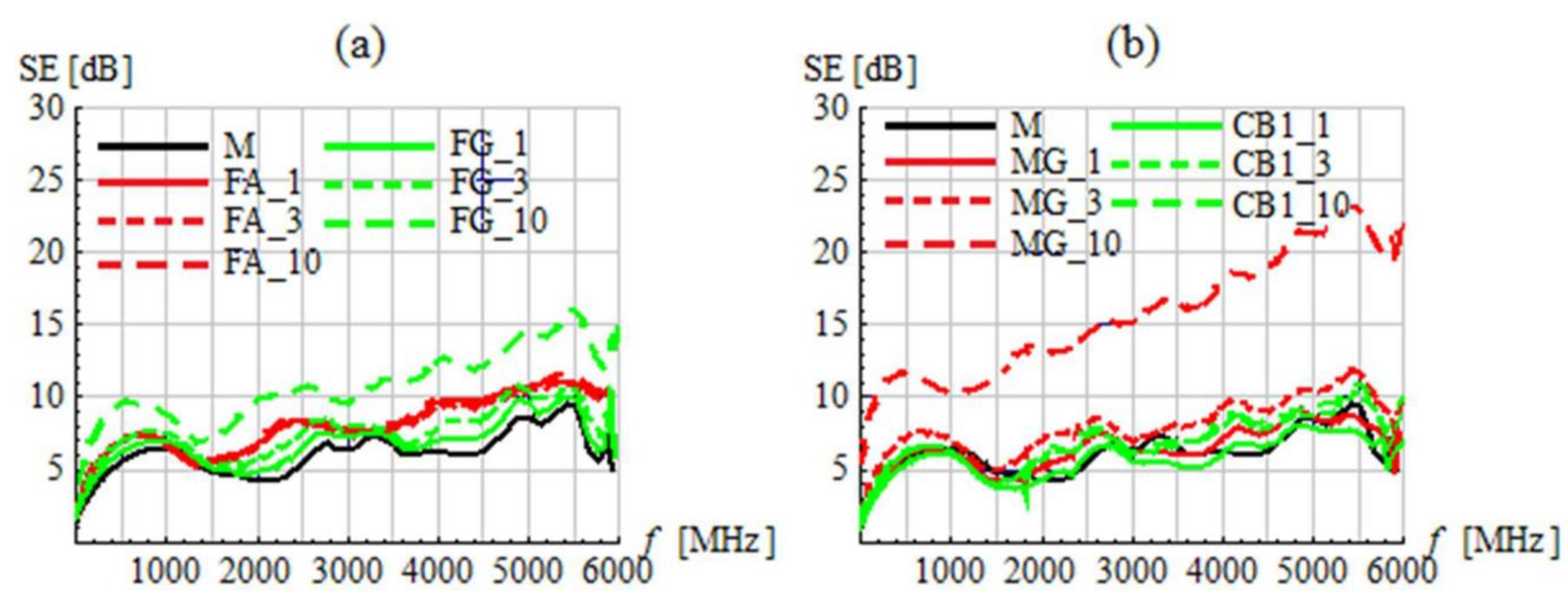
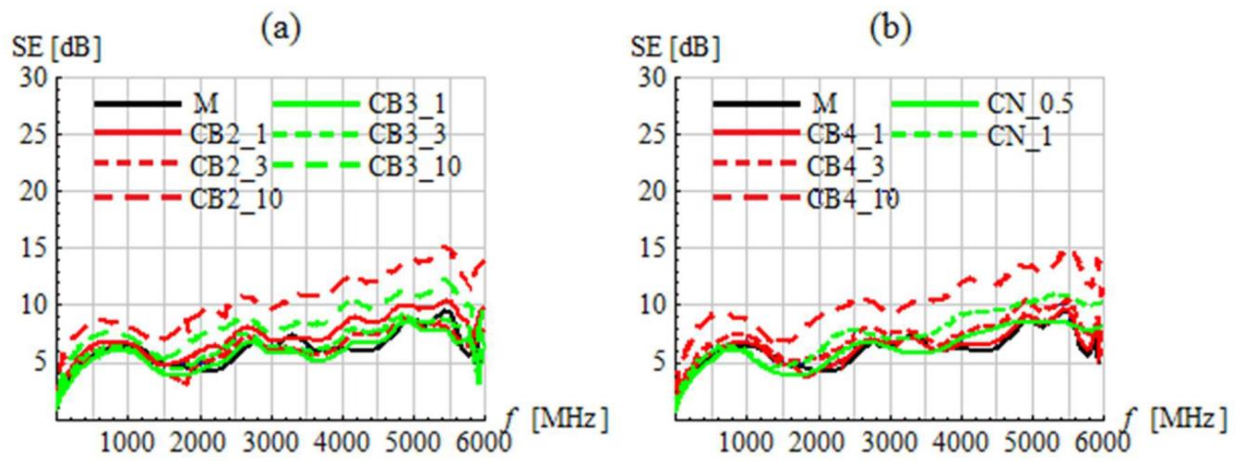
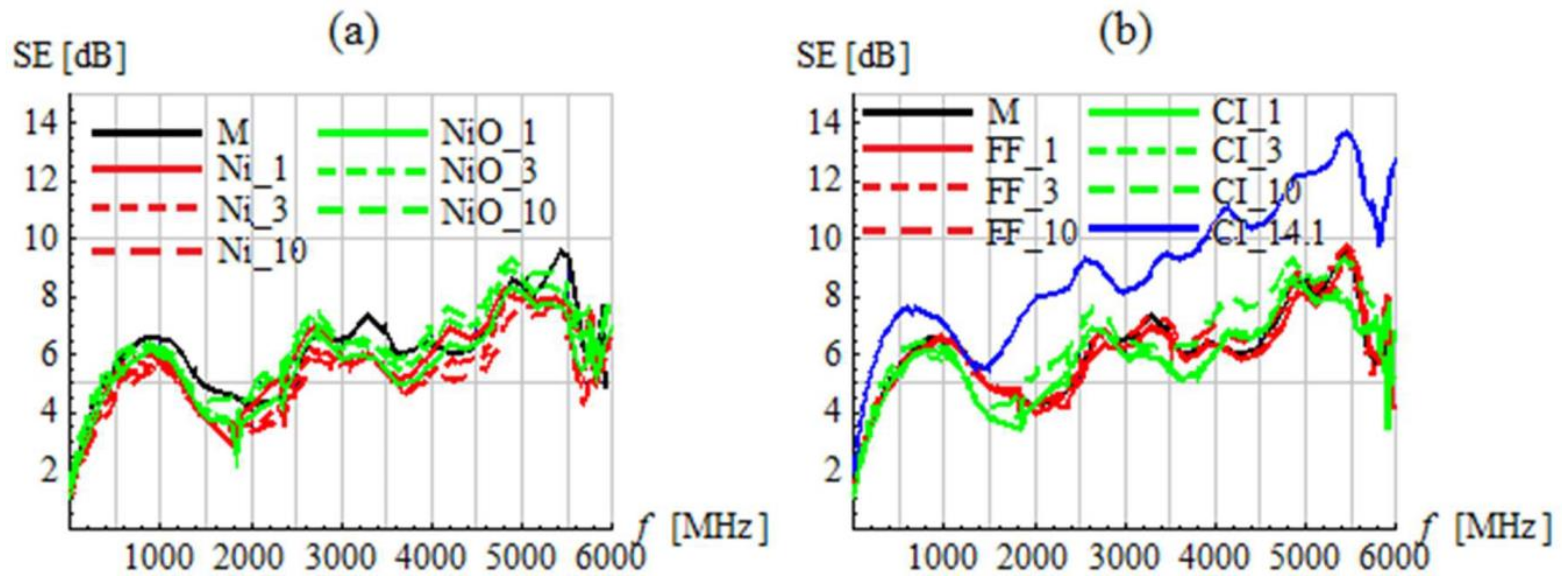
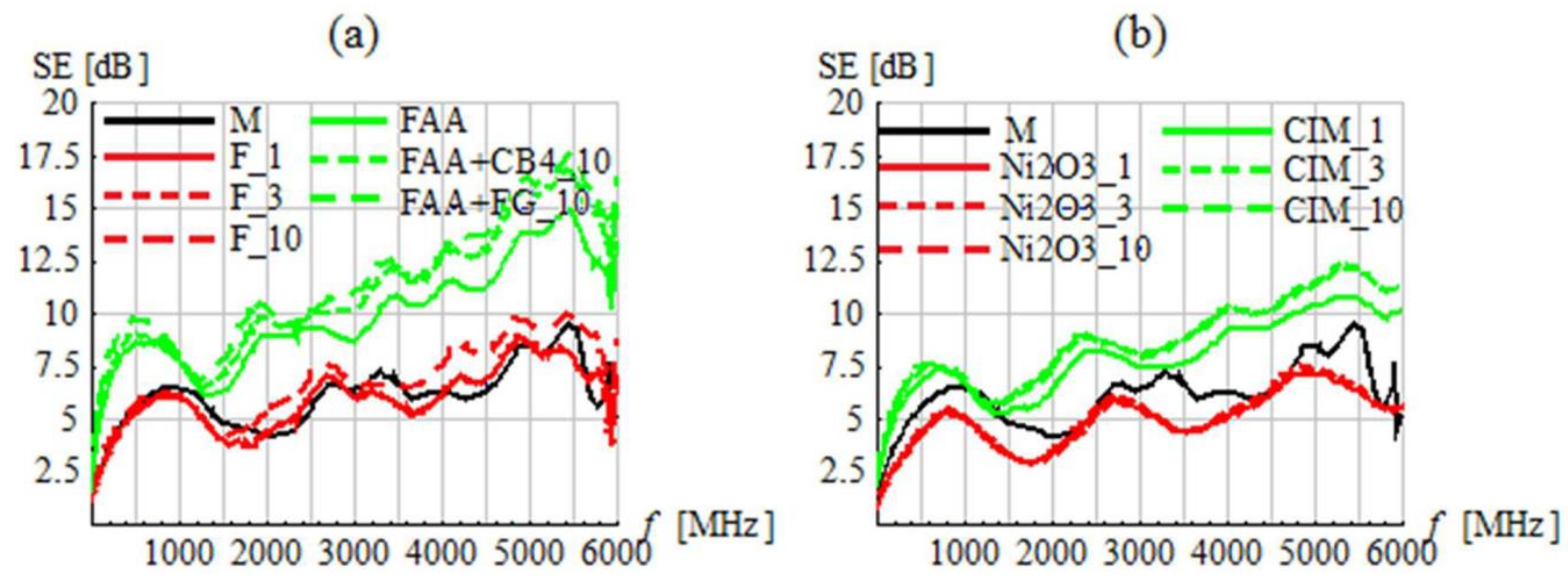
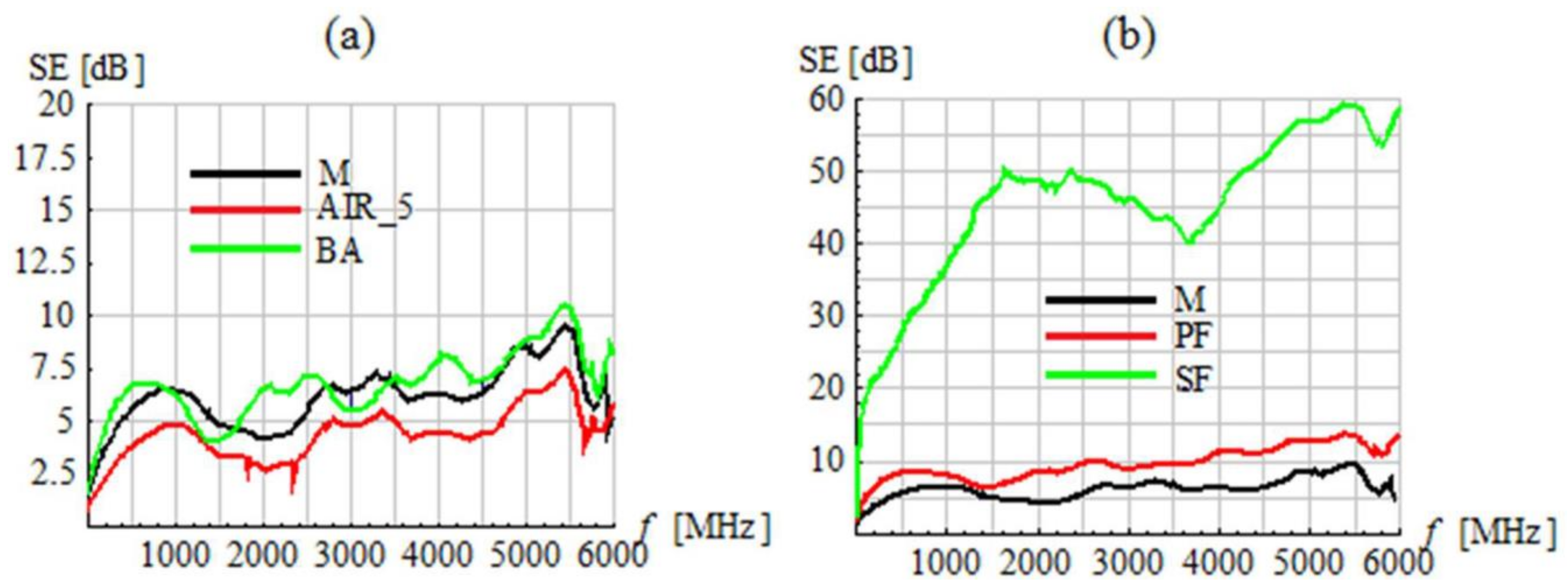
5.2. Shielding Effectiveness

The shielding effectiveness (SE) results are presented in Table 5 and Figure 13, Figure 14, Figure 15, Figure 16 and Figure 17. In Table 5, shielding effectiveness is divided into two frequency ranges: <1 GHz and 1–6 GHz, determined as an overall average in the set frequency range. This division makes it easier to interpret the results, i.e., it makes it possible to determine the shielding effectiveness valid for frequencies < 1 GHz and for the frequency range of 1–6 GHz. Figure 11, Figure 12, Figure 13, Figure 14 and Figure 15 show the continuous shielding effectiveness [dB]-frequency [GHz] dependence in the whole tested range, i.e., 0–6 GHz.
The graphs indicate the nonlinear character of shielding effectiveness in the frequency domain. Nevertheless, a general upward trend in the amount of absorbed energy can be observed as the frequency increases from 0 to 6 GHz. Regardless of the absorbers used, the amplitudes (maxima and minima) of the curves usually occur at the same frequencies.
On the basis of the results presented in Table 5 and Figure 11, Figure 12, Figure 13, Figure 14 and Figure 15, the tested series were grouped according to the HPM pulse shielding effect:
  • specimens AE for which an over 50% improvement in shielding effectiveness was achieved for both <1 GHz and 1–6 GHz in comparison with reference standard mortar M (green): FG_10, MG_10, CB2_10, CB4_10, FAA + CB4_10, FAA + FG_10, PF, SF;
  • specimens BE for which an up to 50% improvement in shielding effectiveness was achieved for both <1 GHz and 1–6 GHz in comparison with reference standard mortar M (blue): FA_1, FA_3, FA_10, FG_1, FG_3, MG_1, MG_3, CB1_3, CB1_10, CB2_1, CB3_10, CB4_1, CB4_3, CN_1, FF_10, CI_10, CI_36, FAA, CIM_1, CIM_3, CIM_10, BA;
  • specimens CE for which no improvement in shielding effectiveness was achieved for frequencies < 1 GHz relative to reference standard mortar M (red): CB1_1, CB2_3, CB3_1, CB3_3, CN_0.5, Ni_1, Ni_3, NiO_1, NiO_3, NiO_10, FF_1, FF_3, CI_1, CI_3, F_1, F_3, F_10, Ni2O3_1, Ni2O3_3, Ni2O3_10, AIR_5.
Table 5. Shielding effectiveness of tested specimens for frequencies < 1 GHz and 1–6 GHz.
No.SpecimenShielding Effectiveness SE
[dB]
No.SpecimenShielding Effectiveness SE
[dB]
<1 GHz1–6 GHz<1 GHz1–6 GHz
1M4.876.5427NiO_14.595.86
2FA_16.228.5928NiO_34.936.45
3FA_36.158.3329NiO_104.626.77
4FA_106.168.5830FF_14.866.32
5FG_15.457.2831FF_34.886.36
6FG_35.998.0632FF_104.896.75
7FG_108.3511.333CI_14.546.18
8MG_15.247.0334CI_34.316.17
9MG_36.328.3735CI_105.036.83
10MG_1010.5616.6836CI_366.509.57
11CB1_14.526.0837F_14.516.37
12CB1_35.437.1138F_34.536.35
13CB1_105.347.4739F_104.677.30
14CB2_15.237.7740FAA7.5110.53
15CB2_34.786.5541FAA + CB4_107.8511.77
16CB2_107.6111.2442FAA + FG_108.4512.29
17CB3_14.736.1543Ni2O3_13.965.29
18CB3_34.846.8844Ni2O3_33.985.41
19CB3_106.359.1345Ni2O3_103.825.42
20CB4_15.286.8146CIM_16.158.37
21CB4_35.697.7547CIM_36.529.30
22CB4_107.9611.0148CIM_106.369.16
23CN_0.54.726.6649AIR_53.484.73
24CN_15.288.0450BA5.767.03
25Ni_14.466.1651PF7.4510.27
26Ni_34.065.6452SF26.7949.30
Specimens AE showed the highest shielding effectiveness and were found to be similarly effective in the absorption of HPM pulses. The best admixtures were found to be: 10% graphite flakes (FG_10), 10% graphite powder (MG_10), 10% carbon black N990 (CB2_10), 10% carbon black P803 (CB4_10), polypropylene fibers (PF) and steel fibers (SF), and also the hybrid admixtures comprising ashporite aggregate with carbon black P803 (FAA + CB4_10) and ashporite aggregate with graphite flakes (FAA + FG_10). In the case of graphite, the obtained results confirmed the results of research for the frequency range of 50–400 MHz regarding the legitimacy of its use in the context of shielding effectiveness [16]. Similarly, the positive effect of using carbon black was confirmed both in the range of 2–8 GHz [22] and 8–18 GHz [29]. In the case of steel fibers and polypropylene fibers, there is lack of knowledge in the literature concerning their impact on shielding effectiveness; hence, the obtained results seem to be of significant importance. Specimens BE showed a 50% improvement in shielding effectiveness and can be considered as moderately effective absorbers. However, considering the high cost of absorbing admixtures, they are unlikely to be commonly used. Specimens CE were found to be ineffective in shielding against HPM pulses in the whole frequency range, and so they are unpromising for future research. In this case, a particularly interesting result is the lack of improvement in shielding effectiveness in the case of using carbon nanotubes, which is in contrast with what is reported in the literature [24,25,26].
Figure 13. Comparison of shielding effectiveness for: (a) standard mortar, standard mortar with fly ash, standard mortar with graphite flakes; (b) standard mortar, standard mortar with graphite powder, standard mortar with carbon black RCB_615.
Energies 16 04062 g013
Figure 14. Comparison of shielding effectiveness for: (a) standard mortar, mortar with carbon black N772, mortar with carbon black N990; (b) standard mortar, standard mortar with carbon black P803, standard mortar with multifaceted carbon nanotubes.
Energies 16 04062 g014
Figure 15. Comparison of shielding effectiveness for: (a) standard mortar, standard mortar with nickel nanopowder, standard mortar with nickel monoxide nanopowder; (b) standard mortar, standard mortar with filler FF and ferrite, standard mortar with carbonyl iron.
Energies 16 04062 g015
Figure 16. Comparison of shielding effectiveness for: (a) standard mortar, standard mortar with ferrite FMS, standard mortar with ashporite aggregate, standard mortar with ashporite aggregate and carbon black P803, standard mortar with ashporite aggregate and graphite flakes FG597; (b) standard mortar, standard mortar with nickel oxide, standard mortar with modified carbonyl iron.
Energies 16 04062 g016
Figure 17. Comparison of shielding effectiveness for: (a) standard mortar, standard mortar with air-entraining admixture Sika PRO3, standard mortar with barite aggregate; (b) standard mortar, standard mortar with propylene fibers, standard mortar with steel fibers.
Energies 16 04062 g017

6. Discussion

The effect of the tested absorbers on the mechanical properties fc and ftb of cement mortar is varied. All Af specimens showed improved mechanical properties in relation to the standard mortar (fc = 48.06 MPa and ftb = 7.88 MPa). This group comprises the following absorbers: SF (with steel fibers), CB4_10 (with 10% carbon black P803), F_1 (with 1% ferrite FMS 0.05), and FA_10 (with 10% fly ash). The improvement in the mechanical properties is not significant, except for SF specimens, which showed fc = 71.89 MPa and ftb = 24.82 MPa. This improvement in the mechanical properties stems from the use of a large amount (Vf = 7.4%) of steel fiber reinforcement. Bf specimens show increased fc and decreased ftb. The results do not significantly differ from the ones for the standard mortar. Cf specimens show slightly lower strengths. The strengths of Cf specimens that were as low as fc = 30 MPa and ftb = 5 MPa (except for AIR_5: fc = 16.09 MPa, ftb = 4.06 MPa) do not disqualify the proposed admixtures from use in both construction materials and finishing materials (e.g., plasters).
The test results indicate that the mortar with steel fiber (SF) reinforcement achieved the highest HPM shielding capability. The amount of introduced fibers is quite large, whereby the fibers are in mutual contact in the cement matrix. The shielding capability of this series was found to be twice as high as that of the other AE specimens. So, high shielding effectiveness can be ascribed to the synergy of two phenomena: (1) the effect of the specific gravity, which in the case of steel fibers was the highest (7.5 g/cm3) among the admixtures used, on the shielding effectiveness of the absorbers and (2) the conduction of electric charges by steel fibers, whereby at an appropriate spacing of the fibers, the Faraday cage effect can arise. These factors have a positive influence on the shielding results, but the second factor seems to be more significant. These suppositions need to be corroborated by further research conducted on a larger number of specimens (models).
Whereas, the mortar series with a high polypropylene fiber (PF) content is characterized by a lower specific gravity (in comparison with the SF specimen) and a limited ability to conduct electric charges. Hence, the shielding effect of absorbers which are insulators is different than that of electrical conductors. Even though the ability of the PF specimen to absorb electric charges is much lower than that of the specimen containing steel fibers (SF), its shielding effectiveness in comparison to the standard mortar is high, exceeding 50%. The test results indicate that shielding effectiveness, albeit lower, is also achievable in the case of specimens with an admixture of electrically non-conducting absorbers.
As part of the present research, shielding effectiveness was sought through the use of both high-density absorbers exhibiting the Faraday cage effect and electrically non-conducting insulators. However, hybrid combinations within one cement paste were found to be ineffective, as evidenced by the FAA + CB4_10 and FAA + FG_10 series. This means that, instead of seeking combinations of absorbers significantly differing in their density and electrical conductibility to be incorporated into a single composite, one should focus on hybrid layered solutions as their synergy seems to be most effective, which further research should demonstrate.

7. Conclusions

As part of this research, the effect of a wide spectrum of admixtures used in various quantities on the mechanical properties and electromagnetic wave damping effectiveness of cement-based mortars was investigated. The investigations included compressive and flexural strength tests and measurements of HPM pulse shielding effectiveness in the frequency range of 0–6 GHz. On this basis, conclusions useful to the engineering practice were formulated.
The noted decreases in the strength of cement composites with some absorber admixtures do not disqualify them from use as construction materials (see Section 5.1.), and in the case of insufficient strength, the difference can be eliminated through, e.g., the dimensions of the structural components, a fumed silica admixture, and dispersed reinforcement, if such a need arises.
Both qualitatively and quantitatively varied shielding effectiveness effects were obtained. The most effective with regards to protection against electromagnetic waves are admixtures of: steel and propylene fibers, graphite flakes and powder, and carbon black, as well as the following hybrid admixtures: ashporite aggregate with carbon black and ashporite aggregate with graphite flakes. The choice of a particular admixture depends on the planned cost and effects.
The following final conclusions can be drawn from this study:
  • The specimens with a high steel fiber content show the greatest improvement in mechanical properties (fc, ftb) and in HPM impulse shielding effectiveness in comparison to the standard mortar. The great improvement in shielding effectiveness can be ascribed to the probable occurrence of the Faraday cage effect.
  • Electric charge conducting admixtures, such as carbon black or graphite, show an improvement in their ability to absorb HPM pulses as the admixture content in the mortar increases, but at the admixture content of 10% by the weight of the cement, the compressive and flexural strength of the cement paste decreases.
  • The use of absorbers (e.g., a large amount of polypropylene fibers), which reduce the possibility of electric charge flow, results in the effective shielding of HPM pulses, but this effect is weaker than in the case of the electric charge conducting specimens.
  • The test results indicate that the use of admixtures in a hybrid configuration to improve the synergistic electromagnetic radiation shielding effect makes sense. However, admixtures significantly differing in their specific gravity and electrical conductivity should not be introduced into the same cement paste but rather separately into cement pastes placed in layers perpendicularly to the direction of HPM pulse action.
  • The optimization and development of the proposed hybrid solutions requires further extensive research in this regard (e.g., including microstructure analysis of cementitious mortars [49]).

Author Contributions

Conceptualization, T.T. and A.R.; methodology, M.M. and D.L.; software, K.M.; validation, P.N., M.S. and D.S.; formal analysis, K.J. and W.P.; investigation, M.M., D.L., K.M., P.N. and T.T.; resources, T.T.; data curation, A.R.; writing—original draft preparation, P.N.; writing—review and editing, M.M.; visualization, K.M.; supervision, T.T.; project administration, M.M.; funding acquisition, T.T. and A.R. All authors have read and agreed to the published version of the manuscript.

Funding

This work was supported by the Polish National Centre for Research and Development DOB-1-3/1/PS/2014 within the project “Methods and ways of protection and defence against HPM impulses”, pending within the strategic project: “New weaponry and defense systems of directed energy”.

Data Availability Statement

The data presented in this study are available in [47].

Conflicts of Interest

The authors declare no conflict of interest. The funders had no role in the design of the study; in the collection, analyses, or interpretation of data; in the writing of the manuscript; or in the decision to publish the results.

References

  1. Kuchta, M.; Paś, J. Electromagnetic terrorism—Threats in buildings. Bull. Milit. Univ. Technol. 2015, 64, 135–147. (In Polish) [Google Scholar] [CrossRef]
  2. Dras, M.; Kałuski, M.; Szafrańska, M. HPM pulses—Disturbances and systems interaction—Basic issues. Przegląd Elektrotechniczny 2015, 11, 11–14. (In Polish) [Google Scholar]
  3. Kołodziejski, J.F.; Kubiak, I. Protection of Electronic Equipment against Directed Energy of Electromagnetic Radiation. Elektronika B2B. (In Polish). Available online: https://elektronikab2b.pl/technika/31417-ochrona-sprzetu-elektronicznego-przed-kierowana-energia-promieniowania-elektromagnetycznego (accessed on 8 March 2023).
  4. Koppel, T.; Shishkin, A.; Haldre, H.; Toropov, N.; Tint, P. Reflection and transmission properties of common construction materials at 2.4 GHz frequency. Energy Procedia 2017, 113, 158–165. [Google Scholar] [CrossRef]
  5. Ozturk, M.; Depci, T.; Bahceci, E.; Karaaslan, M.; Akgol, O.; Sevim, U.K. Production of new electromagnetic wave shielder mortar using waste mill scales. Constr. Build. Mater. 2020, 242, 118028. [Google Scholar] [CrossRef]
  6. Wanasinghe, D.; Aslani, F. A review on recent advancement of electromagnetic interference shielding novel metallic materials and processes. Compos. Part B Eng. 2019, 176, 107207. [Google Scholar] [CrossRef]
  7. Zhang, X.; Sun, W. Electromagnetic shielding and absorption properties of fiber reinforced cementitious composites. J. Wuhan Univ. Technol Sci. Ed. 2012, 27, 172–176. [Google Scholar] [CrossRef]
  8. Wanasinghe, D.; Aslani, F.; Ma, G.; Habibi, D. Advancements in electromagnetic interference shielding cementitious composites. Constr. Build. Mater. 2020, 231, 117116. [Google Scholar] [CrossRef]
  9. Xie, P.; Gu, P.; Beaudoin, J.J. Electrical percolation phenomena in cement composites containing conductive fibres. J. Mater. Sci. 1996, 31, 4093–4097. [Google Scholar] [CrossRef]
  10. Ma, X.; Zhang, Q.; Luo, Z.; Lin, X.; Wu, G. A novel structure of Ferro-Aluminum based sandwich composite for magnetic and electromagnetic interference shielding. Mater. Des. 2016, 89, 71–77. [Google Scholar] [CrossRef]
  11. Sato, H.; Domae, H.; Takahashi, M.; Abe, M. Reflection and transmission control of electromagnetic wave for concrete walls. Electron. Commun. JPN (Part II Electron.) 2000, 83, 12–21. [Google Scholar] [CrossRef]
  12. Luoa, J.; Wanga, S.; Penga, S.; Zhangb, T.; Haoa, G.; Xiaoa, L.; Hua, Y.; Jianga, W. High-performance electromagnetic wave absorbers based on Fe-based MOFs-derived Fe/C composites. Synth. Met. 2021, 272, 116663. [Google Scholar] [CrossRef]
  13. Ozturk, M.; Sevim, U.K.; Akgol, O.; Unal, E.; Karaaslan, M. Investigation of the mechanic, electromagnetic characteristics and shielding effectiveness of concrete with boron ores and boron containing wastes. Constr. Build. Mater. 2020, 252, 119058. [Google Scholar] [CrossRef]
  14. Majcher, K.; Musiał, M.; Pakos, W.; Różański, A.; Sobótka, M.; Trapko, T. Methods of Protecting Buildings against HPM Radiation—A Review of Materials Absorbing the Energy of Electromagnetic Waves. Materials 2020, 13, 5509. [Google Scholar] [CrossRef] [PubMed]
  15. Majcher, K.; Musiał, M.; Pakos, W.; Różański, A.; Sobótka, M.; Trapko, T. A Systematic Review of HPM Energy Absorbers for Building Applications. Energies 2021, 14, 6061. [Google Scholar] [CrossRef]
  16. Yee, S.K.; Jenu, M.Z.M. Shielding effectiveness of concrete with graphite fine powder in between 50 MHz to 400 MHz. In Proceedings of the 2013 Asia-Pacific Symposium on Electromagnetic Compatibility (APEMC), Melbourne, Australia, 20–23 May 2013. [Google Scholar] [CrossRef]
  17. Wanasinghe, D.; Aslani, F.; Ma, G. Electromagnetic shielding properties of cementitious composites containing carbon nanofibers, zinc oxide, and activated carbon powder. Constr. Build. Mater. 2021, 285, 122842. [Google Scholar] [CrossRef]
  18. Wang, C.; Li, J.; Guo, S. High-performance electromagnetic wave absorption by designing the multilayer graphene/thermoplastic polyurethane porous composites with gradient foam ratio structure. Compos. Part A Appl. Sci. Manuf. 2019, 125, 105522. [Google Scholar] [CrossRef]
  19. Mazzoli, A.; Corinaldesi, V.; Donnini, J.; Di Perna, C.; Micheli, D.; Vricella, A.; Pastore, R.; Bastianelli, L.; Moglie, F.; Mariani Primiani, V. Effect of graphene oxide and metallic fibers on the electromagnetic shielding effect of engineered cementitious composites. J. Build. Eng. 2018, 18, 33–39. [Google Scholar] [CrossRef]
  20. Zhu, B.; Li, Y.; Tian, Y.; Wang, K.; Wang, Y.; Wen, G.; Liang, L.; Zhang, K.; Li, G. Rational design of FeCo/C/FA by recycling of fly ash for electromagnetic pollution. Coll. Surf. A Physicochem. Eng. Asp. 2021, 627, 127127. [Google Scholar] [CrossRef]
  21. Ozturk, M.; Karaaslan, M.; Akgol, O.; Sevim, U.K. Mechanical and electromagnetic performance of cement based composites containing different replacement levels of ground granulated blast furnace slag, fly ash, silica fume and rice husk ash. Cem. Concr. Res. 2020, 136, 106177. [Google Scholar] [CrossRef]
  22. Guan, H.; Liu, S.; Duan, Y.; Cheng, J. Cement based electromagnetic shielding and absorbing building materials. Cem. Concr. Compos. 2006, 28, 468–474. [Google Scholar] [CrossRef]
  23. Cao, J.; Chung, D.D.L. Coke powder as an admixture in cement for electromagnetic shielding. Carbon 2003, 41, 2433–2436. [Google Scholar] [CrossRef]
  24. Chung, D.D.L. Review article: Comparison of submicron-diameter carbon filaments and conventional carbon fibers as fillers in composite materials. Carbon 2001, 39, 1119–1125. [Google Scholar] [CrossRef]
  25. Fu, X.; Chung, D.D.L. Submicron-diameter-carbon-filament cement–matrix composites. Carbon 1998, 36, 459–462. [Google Scholar] [CrossRef]
  26. González, M.; Mokry, G.; De Nicolás, M.; Baselga, J.; Pozuelo, J. Carbon Nanotube Composites as Electromagnetic Shielding Materials in GHz Range. In Carbon Nanotubes—Current Progress of Their Polymer Composites; Berber, M.R., Hafez, I.H., Eds.; IntechOpen Ltd.: London, UK, 2016; pp. 297–321. [Google Scholar] [CrossRef]
  27. Cao, M.S.; Wang, X.X.; Cao, W.Q.; Yuan, J. Ultrathin graphene: Electrical properties and highly efficient electromagnetic interference shielding. J. Mater. Chem. C 2015, 3, 6589–6599. [Google Scholar] [CrossRef]
  28. Cao, J.; Chung, D.D.L. Use of fly ash as an admixture for electromagnetic interference shielding. Cem. Concr. Res. 2004, 34, 1889–1892. [Google Scholar] [CrossRef]
  29. Duan, Y.; Liu, S.; Wen, B.; Guan, H.; Wang, G. A discrete slab absorber: Absorption efficiency and theory analysis. J. Compos. Mater. 2006, 40, 1841–1851. [Google Scholar] [CrossRef]
  30. Yao, W.L.; Xiong, G.X.; Yang, Y. Electromagnetic shielding effectiveness of nickel fiber-reinforced cement composites. Mater. Sci. Forum. 2017, 898, 2065–2070. [Google Scholar] [CrossRef]
  31. Lu, Z.; Jian, C.; Wan, S.; Liu, P. Research on New Technology on Protection of Electronic Systems from High Power Electromagnetic Pulse. In Proceedings of the Progress Electromagnetics Research Symposium, Xi’an, China, 22–26 March 2010. [Google Scholar]
  32. Wu, L.Z.; Ding, J.; Jiang, H.B.; Chen, L.F.; Ong, C.K. Particle size influence to the microwave properties of iron based magnetic particulate composites. J. Magn. Magn. Mater. 2005, 285, 233–239. [Google Scholar] [CrossRef]
  33. Wang, M.; Duan, Y.; Liu, S.; Li, X.; Ji, Z. Absorption properties of carbonyl-iron/carbon black double-layer microwave absorbers. J. Magn. Magn. Mater. 2009, 321, 3442–3446. [Google Scholar] [CrossRef]
  34. Chmielińska, J.; Kuchta, M.; Kubacki, R.; Dras, M.; Wierny, K. Wybrane metody ochrony urządzeń elektronicznych przed bronią elektromagnetyczną. Przegląd Elektrotechniczny 2016, 92. (In Polish) [Google Scholar] [CrossRef]
  35. Valko, L.; Bucek, P.; Dosoudil, R.; Usakova, M. Magnetic Properties of Ferrite-Polymer Composites. J. Electr. Eng. 2003, 54, 100–103. [Google Scholar]
  36. Gairola, S.P.; Vivek, V.; Singh, A.; Purohit, L.P.; Kotnala, R.K. Modified Composition of Barium ferrite to act as a Microwave Absorber in X-band Frequencies. Solid. State Commun. 2010, 150, 147–151. [Google Scholar] [CrossRef]
  37. Zhang, X.; Sun, W. Microwave absorbing properties of double-layer cementitious composites containing Mn–Zn ferrite. Cem. Concr. Compos. 2010, 32, 726–730. [Google Scholar] [CrossRef]
  38. Guan, B.; Ding, D.; Wang, L.F.; Wu, J.; Xiong, R. The electromagnetic wave absorbing properties of cement-based composites using natural magnetite powders as absorbers. Mater. Res. Express 2017, 4, 056103. [Google Scholar] [CrossRef]
  39. Garcés, P.; Fraile, J.; Vilaplana-Ortego, E.; Cazorla-Amorós, D.; Alcocel, E.G.; Andión, L.G. Effect of carbon fibres on the mechanical properties and corrosion levels of reinforced portland cement mortars. Cem. Concr. Res. 2005, 35, 324–331. [Google Scholar] [CrossRef]
  40. Jiang, S.; Zhou, D.; Zhang, L.; Ouyang, J.; Yu, X.; Cui, X.; Han, B. Comparison of compressive strength and electrical resistivity of cementitious composites with different nano- and micro-fillers. Arch. Civ. Mech. Eng. 2018, 18, 60–68. [Google Scholar] [CrossRef]
  41. Yang, H.; Cui, H.; Tang, W.; Li, Z.; Han, N.; Xing, F. A critical review on research progress of graphene/cement based composites. Compos. A Appl. Sci. Manuf. 2017, 102, 273–296. [Google Scholar] [CrossRef]
  42. Hemalatha, T.; Ramaswamy, A. A review on fly ash characteristics—Towards promoting high volume utilization in developing sustainable concrete. J. Clean. Prod. 2017, 147, 546–559. [Google Scholar] [CrossRef]
  43. Wu, Q.; Wu, Y.; Tong, W.; Ma, H. Utilization of nickel slag as raw material in the production of Portland cement for road construction. Constr. Build. Mater. 2018, 193, 426–434. [Google Scholar] [CrossRef]
  44. Liu, K.; Li, Y.; Wang, F.; Ren, J.; Xie, H. Modeling and experimental study of multiple factors on mechanical strength of iron sand modified cement mortars. Constr. Build. Mater. 2018, 178, 144–152. [Google Scholar] [CrossRef]
  45. Horszczaruk, E.; Sikora, P.; Zaporowski, P. Mechanical Properties of Shielding Concrete with Magnetite Aggregate Subjected to High Temperature. Procedia Eng. 2015, 108, 39–46. [Google Scholar] [CrossRef]
  46. EN 196-1:2016; Methods of Testing Cement—Part 1: Determination of Strength. Available online: https://www.scirp.org/(S(i43dyn45teexjx455qlt3d2q))/reference/ReferencesPapers.aspx?ReferenceID=762757&utm_campaign=8504943975_134186287357&utm_source=lixiaofang&utm_medium=adwords&gad=1&gclid=EAIaIQobChMI-uKcr57t_gIVWwRyCh1yEwm9EAAYASAAEgKyVfD_BwE (accessed on 14 March 2023).
  47. Glabisz, W.; Hoła, J.; Łydżba, D.; Wójcicki, Z.; Trapko, T.; Majcher, K.P.; Musiał, M.P.; Pakos, W.M.; Różański, A.; Sobótka, M.; et al. Methods and Ways of Protecting and Defending from HPM Impulses—The Technology Concept of Building Absorbers; Report of Faculty of Civil Engineering of Wroclaw University of Science and Technology no SPR 58/2018; Wroclaw University of Science and Technology: Wroclaw, Poland, 2018. [Google Scholar]
  48. ASTM D4935-10; Standard Test Method for Measuring the Electromagnetic Shielding Effectiveness of Planar Materials. Available online: https://shieldingeffectiveness.com/astm-d-4935-10/ (accessed on 14 March 2023).
  49. Stefaniuk, D.; Sobótka, M.; Jarczewska, K.; Logoń, D.; Majcher, K.; Musiał, M.; Niewiadomski, P.; Pakos, W.; Różański, A.; Trapko, T. Microstructure properties of cementitious mortars with selected additives for electromagnetic waves absorbing applications. Cem. Concr. Compos. 2022, 134, 104732. [Google Scholar] [CrossRef]
Figure 2. Construction composites: ordinary vs. enhanced (effectively shielding against electromagnetic waves and having the desired mechanical properties).
Energies 16 04062 g002
Figure 7. Diagram of shielding effectiveness measuring system.
Energies 16 04062 g007
Figure 8. Molds (adapters) for forming specimens of mortars with absorbing material admixture.
Energies 16 04062 g008
Table 1. Materials and characteristics.
SymbolComponentsCharacteristics
-Portland cement CEM I 42.5RSupplied by Górażdże Cement LC, Górażdże, Poland.
Characterized by the specific density of 3090 kg/m3 and the specific surface of 4090 cm2/g.
-Quartz aggregate CENAccording the standard PN-EN 196-1 [46].
The maximum particle size < 2 mm, the bulk density of 1440 kg/m3, the specific density of 2620 kg/m3.
-Mains potable waterWith the temperature of 20 °C.
FAAAshporite aggregateSupplied by CERTYD, Białystok, Poland.
Obtained from fly ash subjected to an industrial thermal process, with the maximum particle size being <2 mm, the bulk density of 900 kg/m3 ± 10%, and the <0.063 mm particles content of 30%.
BABarite aggregateWith the 0–8 mm fraction, density of 3850 kg/m3, heavy minerals (including BaSO4) content min. 70%.
FAFly ashSupplied by CEZ, Skawina, Poland.
With the specific density of 2190 kg/m3, the <0.063 mm particles content of 83% and the SiO2 content of 54.11%.
FGGraphite in the form of
FG597 flakes
Supplied by SINOGRAF, Toruń, Poland.
With the minimum flake size of 300 µm, the carbon content of 97%, and the bulk density of 600 kg/m3.
MGGraphite in the form of
MG1596 powder
Supplied by SINOGRAF, Toruń, Poland.
With the maximum flake size of µm, the carbon content of 96%, and the bulk density of 200–300 kg/m3.
CB1Carbon black RCB_615Supplied by REOIL, Bukowno, Poland.
With the bulk density of 100–115 kg/m3, the specific surface of 65–80 m2/g, and the particle size distribution of 5–25 µm.
CB2Carbon black N772Supplied by FERMINTRADE, Konin, Poland.
With the iodine absorption of 24–34 g/kg, the maximum ash content of 0.40%, and the minimum pour density of 420 kg/m3.
CB3Carbon black N990Supplied by FERMINTRADE, Konin, Poland.
With the iodine absorption of 6–12 g/kg, the maximum ash content of 0.20%, and the pour density of 600 kg/m3.
CB4Carbon black P803Supplied by FERMINTRADE, Konin, Poland.
With the conventional specific surface of 14–18 m2/g, the maximum ash content of 0.45%, and the pour density of 320–400 kg/m3.
CNMultifaceted carbon nanotubes (mCNT)Supplied by SMART NANOTECHNOLOGIES Inc, Alwernia, Poland.
In the form of powder, with length of 1–25 µm, the bulk density of 230 kg/m3, the specific density of 1750–2100 kg/m3.
NiNickel (Ni) nanopowderSupplied by BIMO TECH, Wrocław, Poland.
With a spherical shape, the particle size of 30–70 nm, the purity of 99.9%, and the specific density of 8900 kg/m3.
NiONickel monoxide (NiO)
nanopowder
Supplied by BIMO TECH, Wrocław, Poland.
With a nearly spherical shape, the particle size of 20–30 nm, the purity of 99.9%, and the bulk density of 760 kg/m3.
FFFiller FF + ferriteCharacterized by the specific density of 4900 kg/m3.
CICarbonyl iron CIP HQSupplied by BASF, Warszawa, Poland.
With an onion skin structure, the minimum Fe content of 97.8%, the C and N content of 0.6–0.9%, and a very small particle size, i.e., 90% (by wt.) of particles < 3 μm, the specific density of 7860 kg/m3.
FFerrite FMS 0.05Supplied by Ferroxcube Poland Ltd, Skierniewice, Poland.
With the composition: ~71% of iron oxide, ~21% of manganese oxide and ~8% of zinc oxide; most of the ferrite (>90%) has a particle size < 60 μm; the bulk density amounts to 1900 kg/m3.
Ni2O3Nickel oxide Ni2O3Characterized by the bulk density of 800 kg/m3, the specific density of 6800 kg/m3.
CIMCarbonyl iron modified with SiO2-
AIRAir-entraining admixture
Sika PRO3
Supplied by SIKA, Warszawa, Poland.
Characterized by the density of 1005 kg/m3.
SFSteel fibersWith a length of 6 mm, a diameter of 0.2 mm and ft = 2500 MPa, and hooked-end steel fibers with a length of 50 mm, a diameter of 1 mm and ft = 1100 MPa, the specific density of 7800 kg/m3.
PFPolypropylene fibersWith a length of 10 mm, a diameter of 0.03 mm and ft = 300–400 MPa, and with a length of 45 mm, a diameter of 0.95 and ft = 400 MPa, the specific density of 900 kg/m3.
Table 2. Mortar designs.
ComponentTypes of Cement Paste
IIIIIIIVVVI
Symbol
MCNFAABASFPF
[g/dm3][g/dm3][g/dm3][g/dm3][g/dm3][g/dm3]
Cement CEM I 42.5R5405405405406751012.5
Quartz aggregate16201620----
Water270400420270506.25506.25
Ashporite aggregate--930---
Barite aggregate---2445--
Standard sand----10001000
Disclaimer/Publisher’s Note: The statements, opinions and data contained in all publications are solely those of the individual author(s) and contributor(s) and not of MDPI and/or the editor(s). MDPI and/or the editor(s) disclaim responsibility for any injury to people or property resulting from any ideas, methods, instructions or products referred to in the content.

