Abstract
In order to reduce the complexity of the brushless DC motor (BLDC)-control-system algorithm while improving the estimation performance of the rotor phase position and the speed of the sensorless motor, a neural network (ANN) control algorithm based on multi-layer perceptron (MLP) topology is proposed. The phase voltage of the motor is conditioned to obtain the phase-voltage signal with a high signal-to-noise ratio, which is used as the input eigenvalue of the multi-layer-perceptron-topology neural network algorithm. The encoder signal is used as the training test data of the MLP-ANN. The first layer of the perceptual neural network estimates the position according to the voltage characteristics with incremental time characteristics. The second layer of the perceptual neural network estimates the speed according to the collected time characteristics and the characteristics of rotor position error. The algorithm after learning and training is digitally discretized and integrated into the motor control system. Experimental tests were carried out under no-load, speed step and load mutation conditions. The experimental results show that the algorithm can accurately estimate the rotor position and speed. The absolute error of the rotor position is within 0.02 rad, and the absolute error of the rotor speed is within 4 rpm. The control system with strong robustness has good dynamic and static characteristics.
1. Introduction
The brushless DC motor (BLDC) is widely used in automotive, aerospace and military equipment, as well as other fields, because of its compact structure, long life, high reliability and low noise [1,2]. The traditional BLDC uses position sensors (such as Hall sensors) or sensors connected to the shaft (such as resolvers and encoders [3]) to complete phase determination, thereby achieving rotor phase switching. However, the use of position sensors increases the cost and installation difficulty of the motor, and the susceptibility to electromagnetic interference may deteriorate the signal measurement in the motor and cause failure [4]. In order to avoid the problems caused by the use of position sensors, obtaining the rotor position and speed information from the electrical signal parameter characteristics of the motor during operation has become an important research direction for motor phase identification and control, such as the phase voltage [5], back electromotive force (BEMF) [6], conduction interval detection of the inverter free-wheel diode [7], current change when the stator core is magnetically saturated [8], state observer [9], artificial intelligence algorithm [9] and other methods. However, these methods increase the complexity of the control system and require large storage space to realize the control strategy and parameter calibration. When the parameters of the controlled object change significantly, the adaptability is poor, the control performance is reduced and the phase lag is critical.
As summarized by Thakar [10], many nonlinear systems, such as motor drivers, are controlled by artificial intelligence algorithms. This category includes a variety of branches, such as artificial neural networks (ANNs), fuzzy logic (FZL) and genetic algorithms [11]. The control strategy based on new artificial intelligence algorithms, such as neural networks and fuzzy control, has opened up new avenues for BLDC control due to its strong self-learning ability, high fault tolerance, good flexibility and easy integration with other algorithms. For example, the fuzzy control algorithm [12] can handle non-statistically uncertain events, EKF [13] can use simple perceptron-based learning algorithms and artificial neural networks can control the system with lower computational requirements. HE et al. [14] proposed a starting-current adaptive control strategy based on the neural network inverse system and a two-degree-of-freedom internal model controller. This strategy uses the least-squares vector algorithm to identify the parameters of the motor and adjusts the parameters of the neural network inverse controller in real time to achieve real-time control of the starting current and ensure that the motor can start normally. EJLALI et al. [15] introduced the trial-and-error method of active learning (ALM) on the basis of the extended Kalman filter. ALM is a new fuzzy modeling method. This algorithm improves the learning effect by obtaining information from its own behavior so it can improve the accuracy of estimates. In addition, artificial neural network technology has been applied to industrial applications related to electric motors, for example, estimating the power consumption of brushless DC motors for unmanned aerial vehicles and electric vehicles [16]; identifying faults in motor rotor and stator components [17]; and using multi-layer artificial neural networks to optimize the performance of brushless DC motors [18] and predict the service life of motors [19]. Learning architecture based on multi-layer-perceptron-topology neural networks has also been extensively studied in estimating the position angle of rotating components (such as axis sensors) [20] and the position of BLDC [21] or speed-control algorithms [22].
The above control system models all introduce complex structures that increase the computational burden and greatly affect the dynamic responsiveness of motor control, making it difficult to achieve ideal control results. Table 1 briefly analyzes the advantages and disadvantages of current main control systems. Compared to the above research, applying neural networks to the estimation of rotor position and speed in brushless DC motors is also a promising research field, using simple computational resources to improve the dynamic response performance and stability of the motor under different operating conditions.

Table 1.
Brief Comparison of Motor Control Strategies.
For BLDC control, a neural-network-estimation algorithm based on multi-layer perceptron (MLP) topology is proposed, which is applied to BLDC rotor parameter estimation to achieve accurate judgment of the motor rotor state. Firstly, the experimental platform of the BLDC motor control system based on a TC275 microcontroller is used to collect signals such as digital encoder and motor reverse-electromotive-force phase voltage. At the same time, AURIX TC275 outputs the complementary PWM of the three-phase inverter, which realizes the open-loop and closed-loop control of no-load, speed step and load mutation of the BLDC. The phase-voltage signal of the motor is used as the input eigenvalue of the MLP-ANN, and the back-propagation algorithm is used to train and learn the neural network algorithm to obtain the best network parameters. The encoder is introduced to mark and compare the estimation hypothesis of neural network training, and the estimation value of the neural network is compared with the reference value obtained from the experiment to judge the effectiveness and accuracy of the estimation method. Finally, the BLDC runs in a non-inductive mode and tests under different working conditions in the range of 120~1600 rpm. The experimental results show that the neural network based on multi-layer-perceptron-topology is used to estimate the position and speed of the BLDC motor rotor. It has good adaptability, accuracy and dynamic superiority, which greatly improves the response speed and control performance of the motor control.
2. Brushless DC Motor Control System
2.1. Brushless DC Motor Drive Strategy
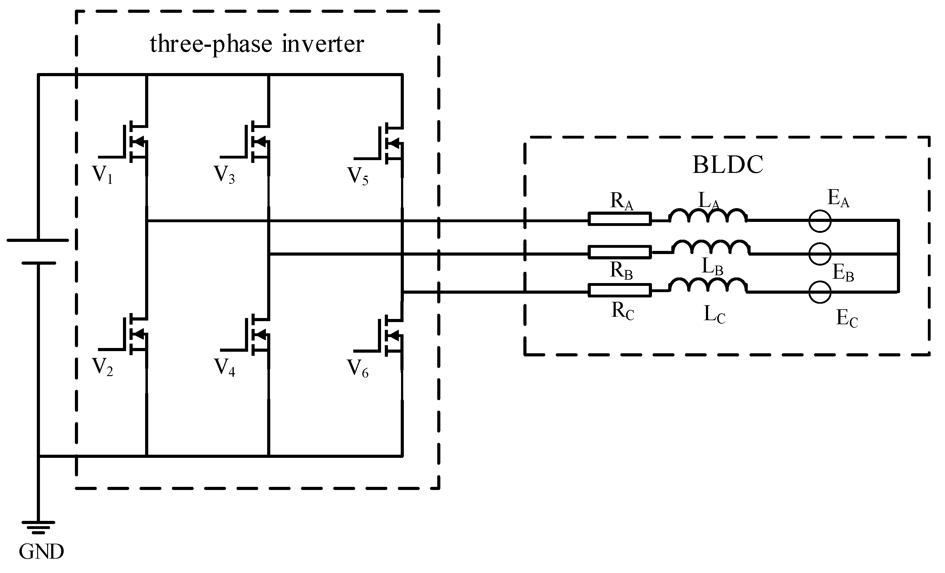
In order to facilitate research and derivation, it is assumed that the three-phase brushless DC motor is an ideal motor, regardless of the influence of the cogging effect and magnetic circuit saturation. Regardless of eddy current and hysteresis loss, the simplified circuit equivalent model of the BLDC is shown in Figure 1.
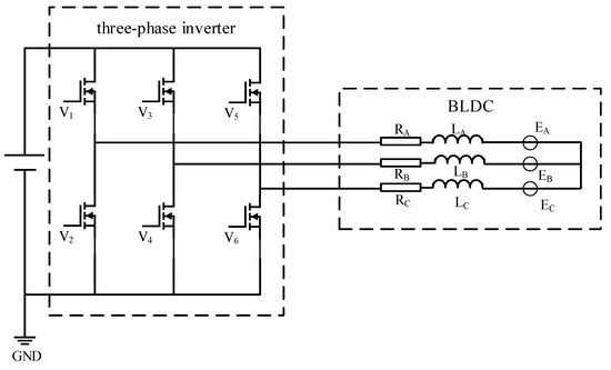
Figure 1.
Equivalent circuit of brushless DC motor system.
This study uses six-step commutation control [23]. When the motor is running, the stator winding is commutated in six steps. Only two-phase stator windings are turned on during commutation. The rotation period of the motor rotor is 360°, each phase winding is connected to 120° and the direction is changed every 60°. According to the order of the six-step commutation method, a complementary PWM signal is generated to control the conduction and disconnection of the power tubes V1~V6 of the inverter to realize the control of the motor. The specific order is shown in Table 2.

Table 2.
Three-phase winding conduction mode of BLDC motor.
2.2. Phase-Voltage Analysis of Brushless Motor
Based on the above model, the matrix form of the stator-winding phase voltage of the three-phase brushless DC motor is as follows:
where is the motor phase (); is the stator resistance (assuming that all winding parameters are the same); is the armature current; and are the self-inductance and mutual inductance (assuming that all windings are constant and similar); and is the trapezoidal back EMF.
Because the neutral point N of the Y-type three-phase winding of the motor is not directly derived, the N-point potential cannot be directly measured. Therefore, the simulated neutral point S is introduced to calculate the equivalent phase voltage . The formula is as follows:
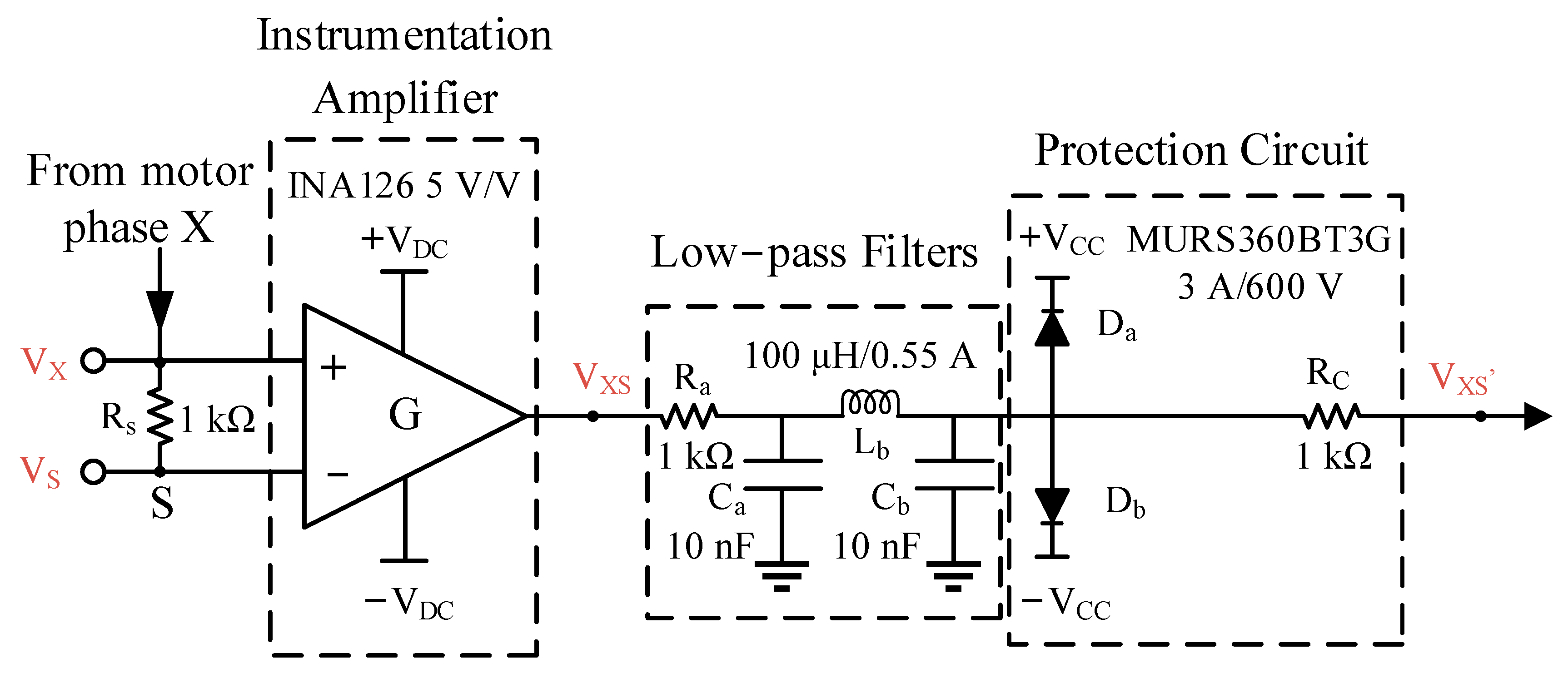
In order to suppress the phase-voltage noise of the motor in different speed ranges and limit the amplitude of the reverse electromotive force, a phase-voltage differential-amplification and filtering-conditioning circuit is designed, as shown in Figure 2.
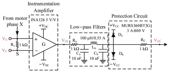
Figure 2.
Signal adjusting circuit of motor phase X.
The electrical signal obtains the phase-voltage signal through a differential amplifier with high common mode suppression and low noise effect, such as the INA126 model with a gain of 5 V/V. Because the output voltage of the three-phase inverter has a high-frequency component, LC and RC low-pass filters are used to attenuate it: a restrictive low-pass filter (,) is used for frequencies < 20 kHz and a low-pass filter (,) is used for high-frequency spurious components from 100 to 200 kHz. In order to avoid the impact of current, undervoltage and overvoltage on data processing in the next stage of the experiment, a current-limiting resistor with a resistance value of 1 kΩ and a MURS360BT3G diode are added in the final stage of the conditioning circuit to protect the circuit. The VADC module of AURIX TC275 has an input voltage range of 0–5 V, a resolution of 12 bits and a sampling frequency of 100 kHz (period of 10 μs). Through the conditioning circuit, the high-frequency component is attenuated so that the VADC module collects pure voltage signals.
2.3. Experimental Platform
Based on the above situation, the open-loop ramp-up model is used to start the motor from the static state without rotor pre-alignment, and the motor is linearly accelerated from zero speed to the reference speed. When the speed is close to 120 rpm, the motor uses closed-loop control, and the angle obtained by the encoder is used as the reference position of the motor rotor. During the experiment of the drive motor, the data related to the rotor position information are collected, and the ANN algorithm is learned and trained. Then, the proposed BLDC sensorless rotor position and velocity-estimation method is evaluated.
The BLDC motor parameters used in this experiment are shown in Table 3.

Table 3.
Main parameters of brushless DC motor.
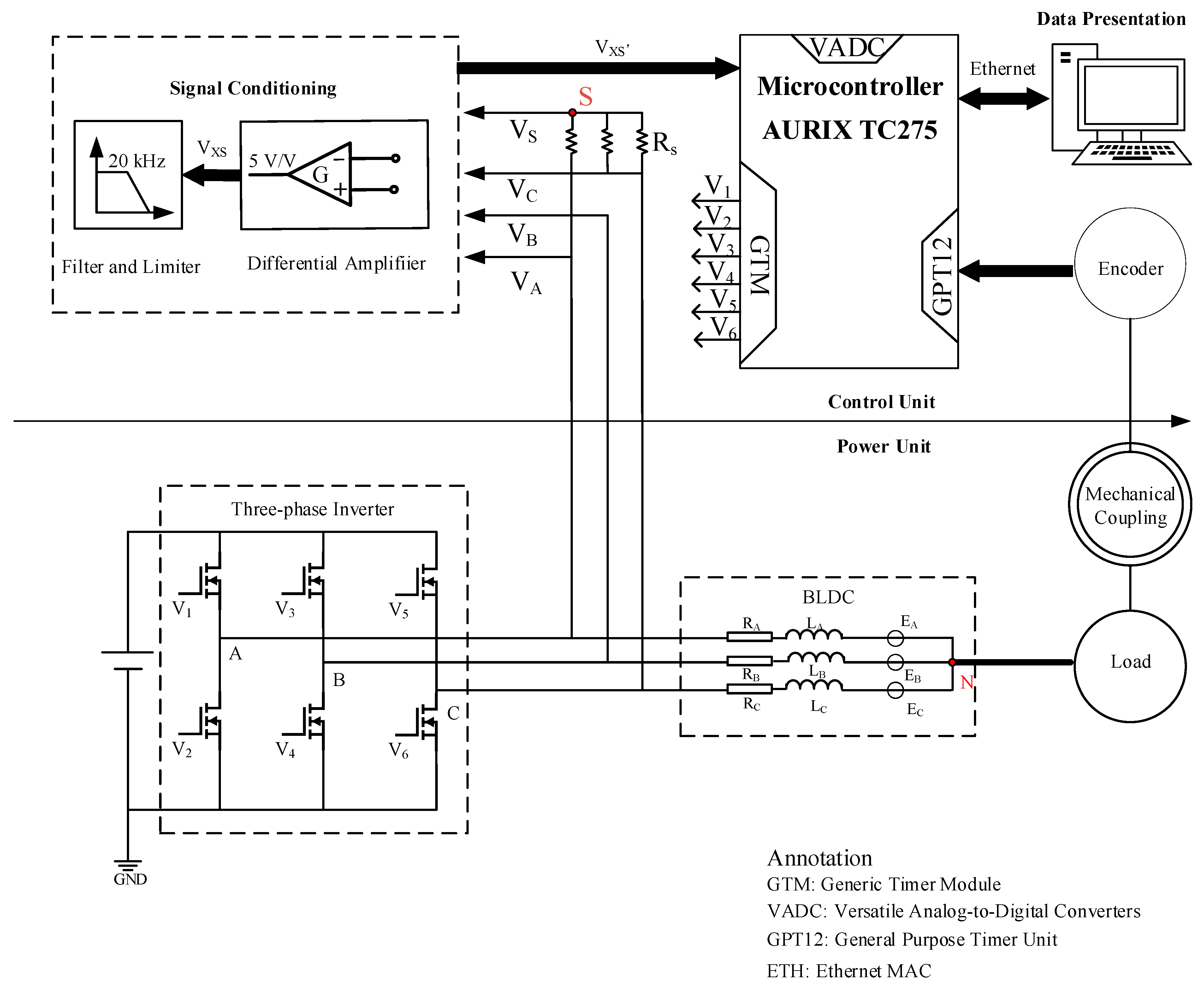
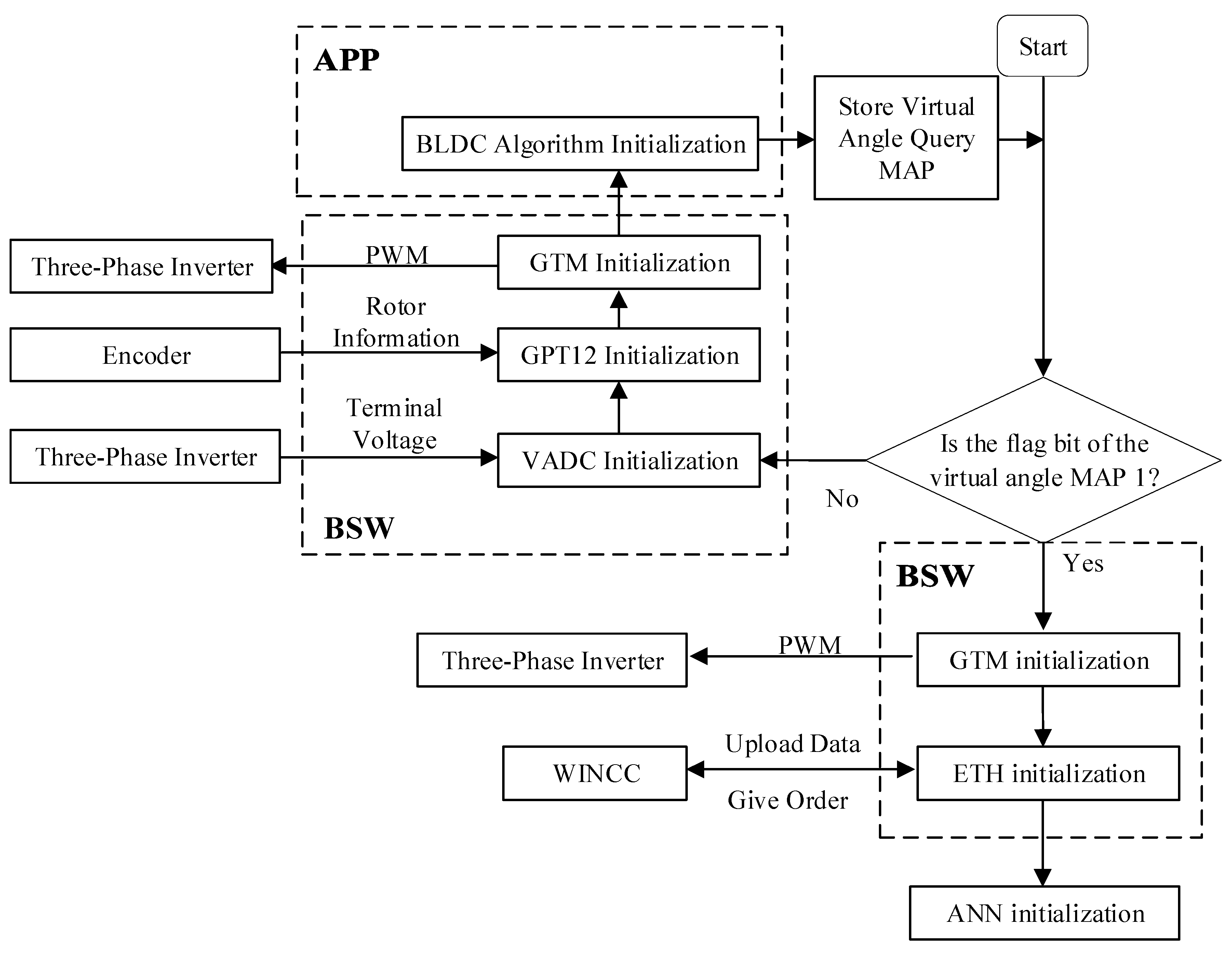
The whole experimental control system is shown in Figure 3 and Figure 4. The driving circuit of the motor consists of a three-phase inverter and a signal conditioning circuit for amplifying and filtering the motor voltage. The control and signal processing of the motor depend on the control platform based on an AURIX TC275 micro-control chip, which can generate a PWM control signal, collect the motor phase voltage and read the encoder pulse. The reference position is measured using an incremental encoder with a resolution of 0.25° and 1024 pulses per revolution.
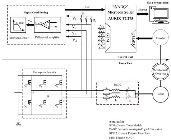
Figure 3.
Brushless DC control system block diagram.
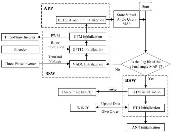
Figure 4.
Software system control block diagram.
3. Motor Rotor Position and Speed-Estimation Neural Network Algorithm
3.1. Angle Virtual Serial Number
In the BLDC control process, the angular-position-detection accuracy of the rotor is closely related to the commutation signal sequence of the motor. However, the number of poles of the motor limits the resolution of the rotor angle and greatly affects the position-detection accuracy of the rotor. In order to accurately identify the actual rotation angle, this paper proposes the concept of a virtual serial number that corresponds to the conversion between the electrical cycle steps of the motor rotor shown in Table 4. A total of 12 rotor steps are provided for each electrical cycle, and each step has a corresponding label (the tangent of the rotation angle) that represents the angle range of each electrical cycle.

Table 4.
Relationship between virtual serial number and rotor position.
The virtual label helps to reduce the influence of noise on the training of neural network data. The sampled continuous-phase-voltage signal is mapped to a discrete output virtual label. A label represents an angle range, which makes the result more effective and less prone to noise distortion. In addition, the virtual sequence number adds 72 labels to the ANN algorithm. Compared with the traditional commutation sequence method, the minimum measurable angle is accurate at 5°, which greatly improves the resolution of the actual rotation angle of the motor rotor. In each virtual label, the average value of the tangent value corresponding to the rotation angle is marked to reduce the detection error, and the average value of the mechanical angle within the same component range is read from the encoder for data training of the ANN algorithm. The control board also obtains the reference position of the encoder and assigns the obtained information to the corresponding virtual label. The ANN uses these data in the learning process of each sequence step to provide subsequent position estimation.
3.2. Position and Velocity-Estimation Algorithm
3.2.1. MLP Topology
The method proposed in this paper is developed based on multi-layer perceptron (MLP) to estimate the rotor position of the motor. The rotor speed estimation is based on the position result, as shown in Figure 5. MLP topology has a simple structure, using low computing resources, low hardware cost and it yields prototype design and implementation in commercial embedded devices [24].

Figure 5.
BLDC rotor neural-network-estimation algorithm flow chart.
The MLP topology is implemented by three layers: the input layer, hidden layer and output layer. In the input layer, the number of nodes is related to the input variables to be processed; in the output layer, the number of nodes depends on the hypothesis function. In the hidden layer, multiple structures with different numbers of nodes are independently developed and trained, and the topology with the maximum success rate in the validation data set is selected. The nonlinear relationship is constructed in the input layer and the output layer, and the activation layer is added. This algorithm selects the commonly used RELU function as the activation function, which is used to hide layer nodes, and the range is limited to max(x,0). The results of the output layer are processed into probability values by the Softmax layer, and the advantages and disadvantages of the current network are quantified by cross-entropy loss.
3.2.2. Motor Rotor Position Estimation
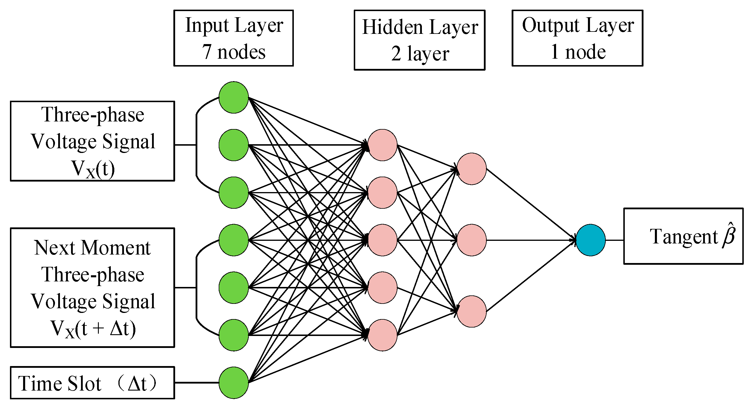
Position-estimation MLP-ANN topology consists of seven input nodes, two hidden layers and one output node, as shown in Figure 6. The input node of the neural network provides a three-phase phase-voltage signal at each acquisition time and a phase-voltage signal at the next time, when it evolves over time. X is the motor phase (A, B and C), and is the time slot for collecting the next feature. The input to output mapping is the tangent component of the estimated rotation angle, not the estimated angle () itself. This simplifies the process of data processing, greatly improves the accuracy of the estimation results and avoids the problem of inconsistent output values.
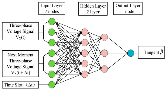
Figure 6.
Rotor-position-estimation ANN.
3.2.3. Motor Rotor Speed Estimation
Speed estimation uses three-layer MLP-ANN topology, which can be equivalent to a traditional observer, to calculate the cumulative sum of the number of mechanical rotor cycles per unit time. In the artificial neural network proposed in this paper, the resolution of speed estimation depends on the rotor-position-estimation error and the correct identification of the motor rotor period.
The speed-estimation method proposed in this paper is divided into two stages. In the first stage, the first set of speed ratio characteristics is calculated according to the rotor position and its time gap. In the second stage, the obtained speed ratio characteristics are input into the ANN algorithm. In order to accurately determine the speed characteristics of the rotor, the ANN algorithm starts with two types of speed characteristics for data sampling. The difference between each position sample and the last sample in the acquisition window is used to calculate the feature ratio of feature 1. It provides the function of an incremental time slot to detect the change and abnormal deviation of rotor instantaneous speed. In the continuous rotor cycle of the motor, speed feature 2 is the speed characteristic of samples with the same virtual serial number position, which provides the monitoring function of position change in the complete mechanical cycle of the rotor to detect the change in the speed cycle. The corresponding velocity ratio characteristics S are as follows:
Among them, is the sampling time of the position sample corresponding to the rotor position; is the size of the acquisition window; is the index of the position sample in the acquisition window; and and are the index of position samples with the same virtual sequence number in two continuous rotor cycles.
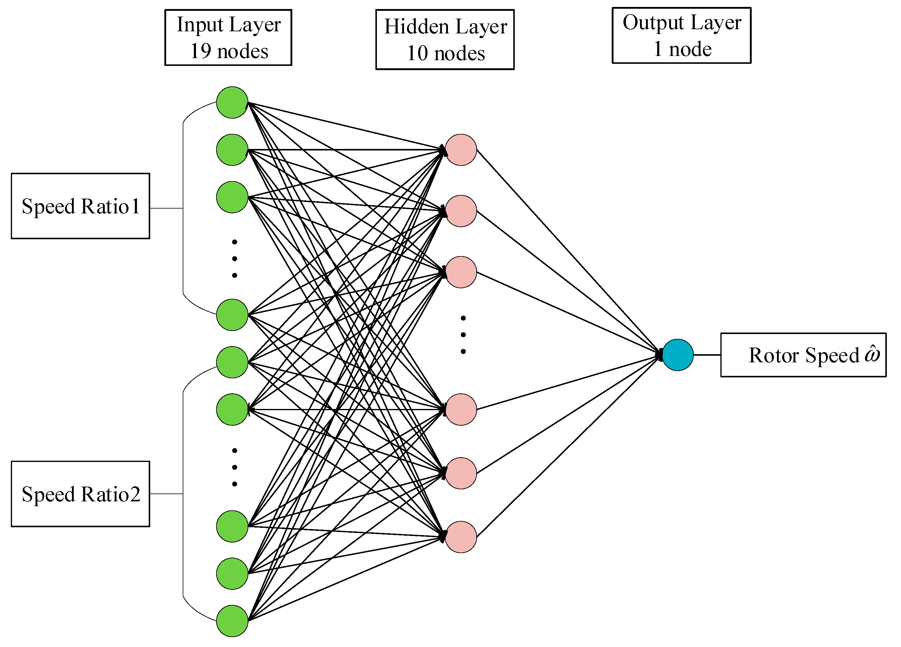
In this experiment, a window of is used to collect the value of velocity feature 1, which provides seven velocity ratios. For the feature of speed ratio 2, because each virtual sequence number provides the rotor position, 12 speed ratio features can be obtained. Therefore, after various evaluation tests, the speed-estimation MLP-ANN topology input layer has 19 nodes, and the hidden layer and the output layer have 10 nodes and 1 node, respectively, as shown in Figure 7.
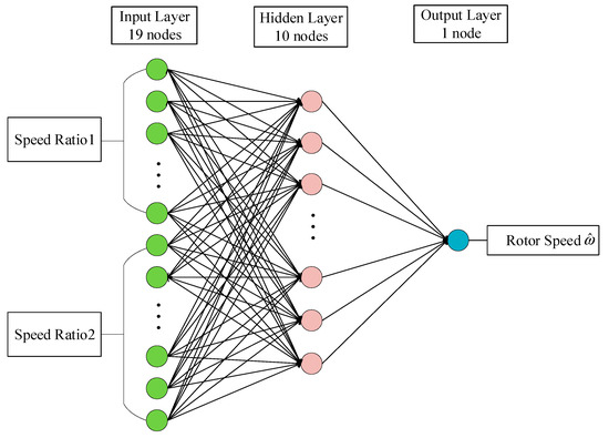
Figure 7.
Rotor-speed-estimation ANN.
3.3. Learning and Training of ANN Algorithm
The measurement of the BLDC phase voltage and encoder signal is used for training, learning and further testing of the ANN algorithm. The learning process of the neural network proposed in this paper includes three stages. The motor is required to operate in sensor-based and sensorless modes. The motor operation process is shown in Figure 8.

Figure 8.
Process of motor operation and data measurement for ANN learning.
In the first stage, the motor is controlled by an open-loop control model and starts from a stationary state. Then, when the speed is close to 120 rpm, the encoder signal is used as the reference position of the control drive. At this stage, the control board measures and stores the phase voltage and encoder data of the motor, and integrates them as a training example for the position-estimation ANN. At the same time, based on these examples and position estimation, the ratio features required for speed estimation are obtained to train the speed-estimation ANN. In the final stage of the experiment, the motor is driven in a sensorless mode to evaluate and test the performance of the proposed method in tracking the encoder signal.
After the ANN algorithm obtains m examples , the back-propagation algorithm is used to train the position-estimation ANN, where , is the input vector of the motor phase voltage and time, and is the output vector of the motor virtual-sequence-number label associated with the encoder position.
Firstly, the weight of each node is randomly initialized, and the obtained motor data are used as the input data of the algorithm (). Next, in the forward-propagation stage of the algorithm, other reasonable data are calculated to obtain the vector group of neuron , where (hidden layer is 2, output layer is 3). Therefore, the assumed output vector group of the ANN is calculated as follows:
where is the RELU activation function of the hidden layer, is the mapping weight matrix from the input layer to the hidden layer and is the activation function of the output layer, and is the mapping weight matrix from the hidden layer to the output layer.
After cross-entropy is obtained by the forward propagation of the ANN algorithm, back propagation is started, that is, parameter optimization begins. The optimization object is the ownership weight and bias in the network. The ANN algorithm obtains the cost error and uses a set of optimal parameters to minimize the error. For the output layer, the error vector is the difference between the actual result and the correct output. For the hidden layer, the error vector is calculated by the product of the output layer error, the hidden output weight matrix and the derivative of the hidden layer activation function applied to the input hidden transformation.
here ‘*’ denotes the elementwise multiplication of vectors and matrices, and ‘T’ denotes the transpose matrix.
In order to better simulate the actual situation of the motor control environment and the neural network learning, training, verification and testing program is speed in the range of 120~1600 rpm, and the upper and lower variable motor speed measurements are specified. The specific data results are shown in Table 5.

Table 5.
ANN algorithm training, verification and test data set.
The experimental data were collected at a sampling frequency of 100 kHz and were randomly assigned to a specific subset of the ANN algorithm data set. The total number of samples collected in this experiment is 475,600, which may contain outliers and missing values. These data are randomly divided into specific subsets according to the ratio column, and the experimental data are processed reasonably to reduce the generalization error of the algorithm and avoid the influence of over-fitting and under-fitting problems of algorithm estimation. A total of 40% of the data is used for algorithm learning training; 10% of the data is used for cross-validation to evaluate the generalization of the ANN. The remaining 50% of the data is used to test and evaluate the independent metrics of the ANN performance after training. After training and testing the ANN algorithm, the motor runs in a sensorless mode based on the estimation of the ANN algorithm. In the full speed range of the experimental tests, the rotor position and speed results estimated by the ANN algorithm are compared with the encoder data to evaluate the estimation performance of the proposed method.
4. Experimental Results and Analysis
4.1. Evaluation Function
In this paper, a neural network model based on MLP topology is obtained through a large number of experimental data. In order to evaluate the estimation performance of the proposed method, F-score and mean absolute error (MAE) in statistics are selected as metrics. The F-score is the harmonic mean of the accuracy and recall rate. When evaluating the proportion of real cases and the total number of instances, it greatly improves the objectivity of the evaluation method.
The F-score is the harmonic mean of the accuracy and recall rate. When evaluating the proportion of real cases and the total number of instances, it greatly improves the objectivity of the evaluation method. The MAE index quantifies the performance of the difference between the estimated value and the target value in a large number of examples and uses the best ANN parameter set as the network weight to achieve the goal of optimizing the difference. The evaluation index calculation formula is as follows:
Among them, P is the accuracy, which is the ratio of true positive to false positive; R is the recall rate, which is the ratio of true positive to false negative; N is the total number of examples; and and are the estimation vector and objective vector, respectively.
In the case where the rotor position is the main result of ANN estimation, corresponds to the reference position from the encoder and corresponds to an angular tangent component, and the rotor estimated position is obtained by the arctangent function:
4.2. Angle Virtual Serial-Number-Estimation Performance
The rotor-speed-estimation algorithm based on the ANN proposed in this paper is based on the rotor position estimation of the motor, and the performance of the method is determined by the ability of the ANN algorithm to judge the virtual sequence number of the rotor. As shown in Table 6, this experiment carried out low-, medium-, high- and extremely-high-speed sampling in the range of 120~1600 rpm of the motor, and ANN experimental tests were performed on more than 40,000 rotor mechanical cycles to analyze the virtual-sequence-number fault state related to the actual position of the rotor.

Table 6.
ANN algorithm test data set.
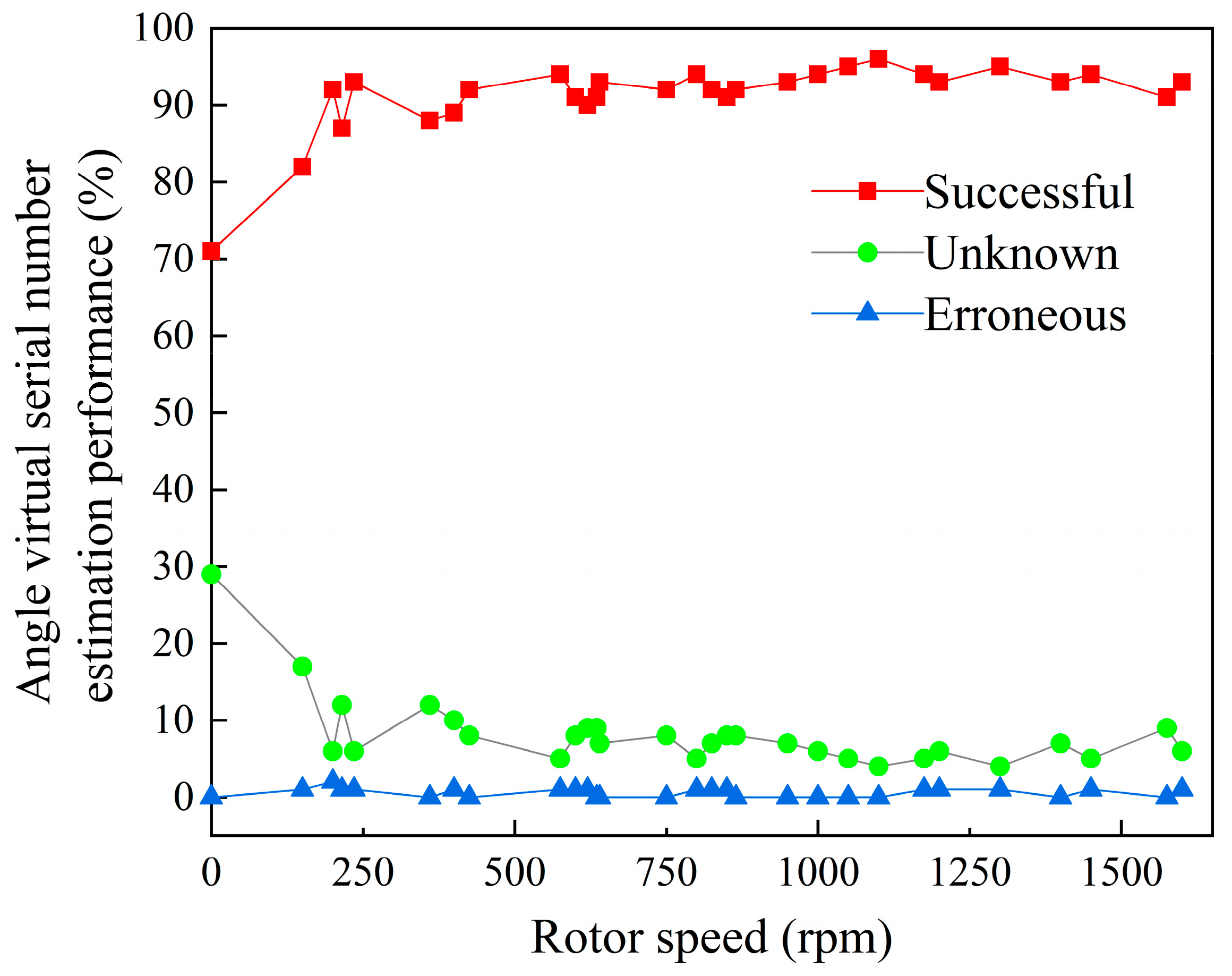
Figure 9 shows the accuracy of the ANN algorithm in judging the virtual sequence number in the whole speed range. In the figure, 93% were true positive, 6.8% were unknown and 0.2% were true negative. Because the operation of the motor rotor close to stationary is not considered in this work, the open-loop ramp model without rotor pre-alignment is directly used and PWM control is used for processing; therefore, when the motor is at a low speed (120~170 rpm), the unknown state of neural network detection increases significantly, but the error is small. With the significant increase in motor speed, the unknown detection state decreases sharply, especially when the motor speed is higher than 180 rpm, and the estimation performance of the ANN algorithm is significantly improved. The proposed method maintains high estimation performance in the full speed range of the motor and decreases in the ultra-low-speed range.
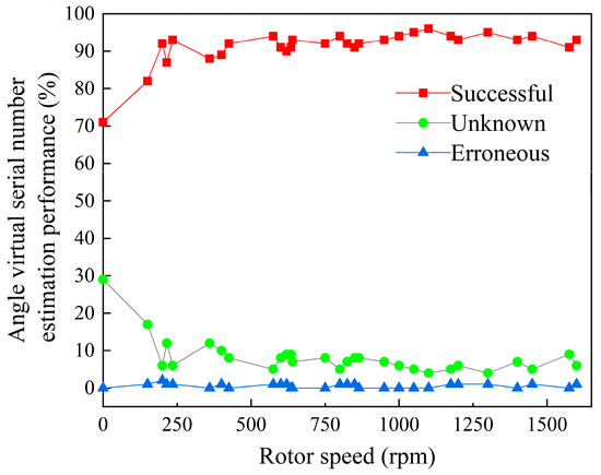
Figure 9.
The estimation performance of ANN algorithm for virtual serial number.
The above data set provides the performance measurement state of the ANN model for the multi-classification virtual sequence number proposed in this paper. The data set is larger than the cross-validation set of the experiment, and the estimation performance mapping of the specific speed interval is accurate. Using big data to evaluate its estimation performance is in line with the purpose of using simple ANN topology and less computing resources to achieve experimental goals. Because the cost of false positives is similar to the cost of false negatives, and because the association between the label of the virtual sequence number and the instance is more important, the F function is preferentially used as a comprehensive evaluation index of the experimental algorithm. In order to simplify the evaluation, this analysis only provides the overall values of these parameters. The overall result of the F-score is 0.967 and the accuracy is 0.935. The data show that the proposed algorithm omits a relatively small number of samples and classifies accurately.
4.3. Rotor Position and Speed-Estimation Performance
In order to verify the performance of the proposed ANN algorithm for rotor position and speed estimation, the experiment compares the measured data of the encoder with algorithm estimation (speed, speed error, rotor position, rotor position error) under different working conditions in the full speed range of the motor (120~1600 rpm) to obtain the relative error (MAE) of the position and speed. The specific control effects are as follows.
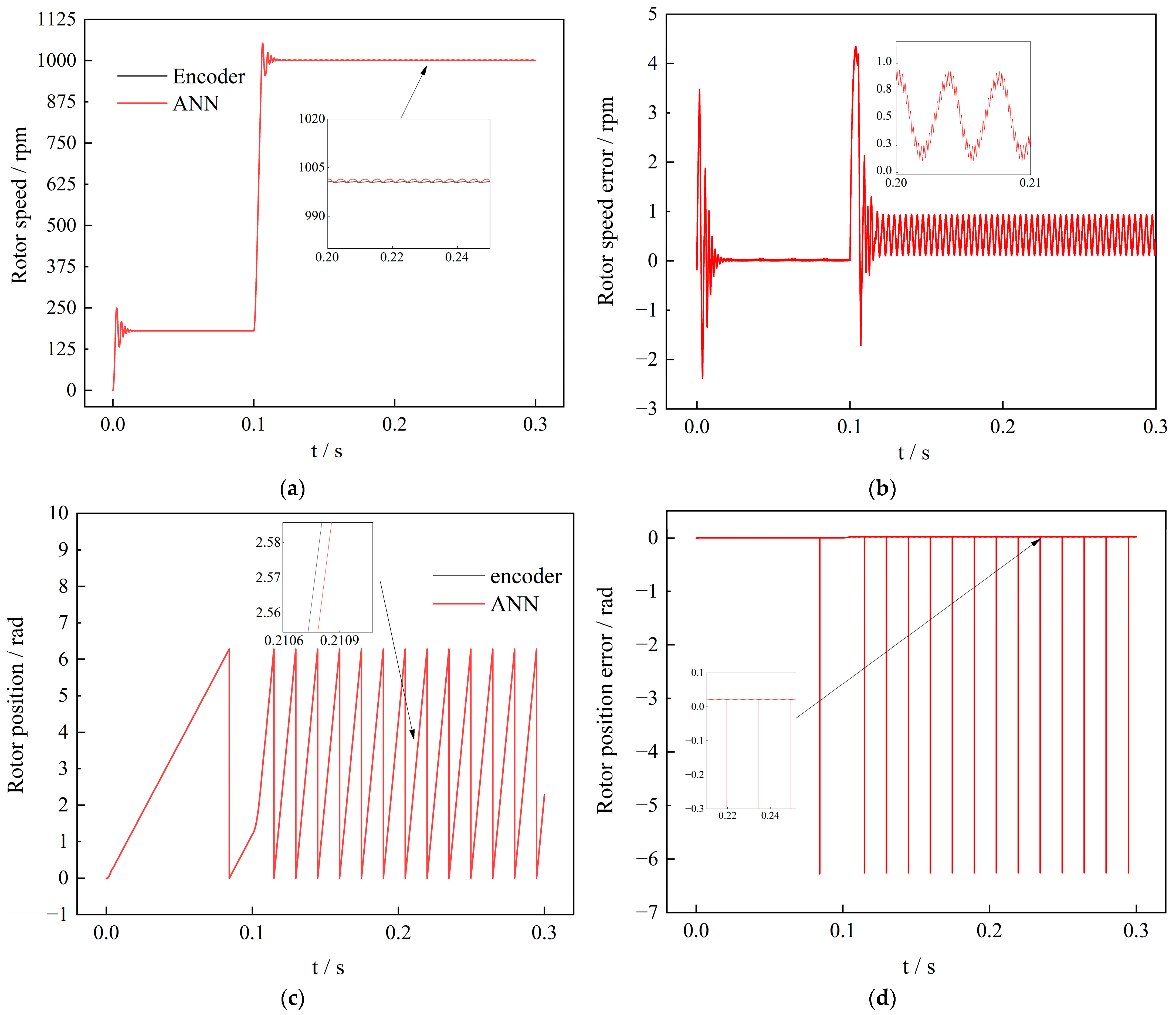
Condition 1: The motor starts at 180 rpm at low speed, and when t = 0.1 s, it changes to 1000 rpm. The experimental results are shown in Figure 10. The maximum error of the rotor position estimated by the ANN algorithm relative to the rotor position of the encoder reference is 0.05 rad, and the maximum speed error is 1 rpm. When the motor speed fluctuates, the control system has a fast response and small overshoot and can achieve more accurate speed tracking.
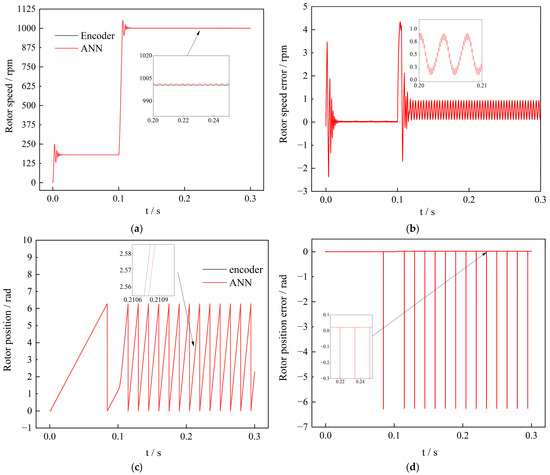
Figure 10.
Experimental results of brushless DC motor under different speed control. (a) Experimental speed diagram; (b) Experimental speed error diagram; (c) Experimental rotor position diagram; (d) Experimental rotor position error diagram.
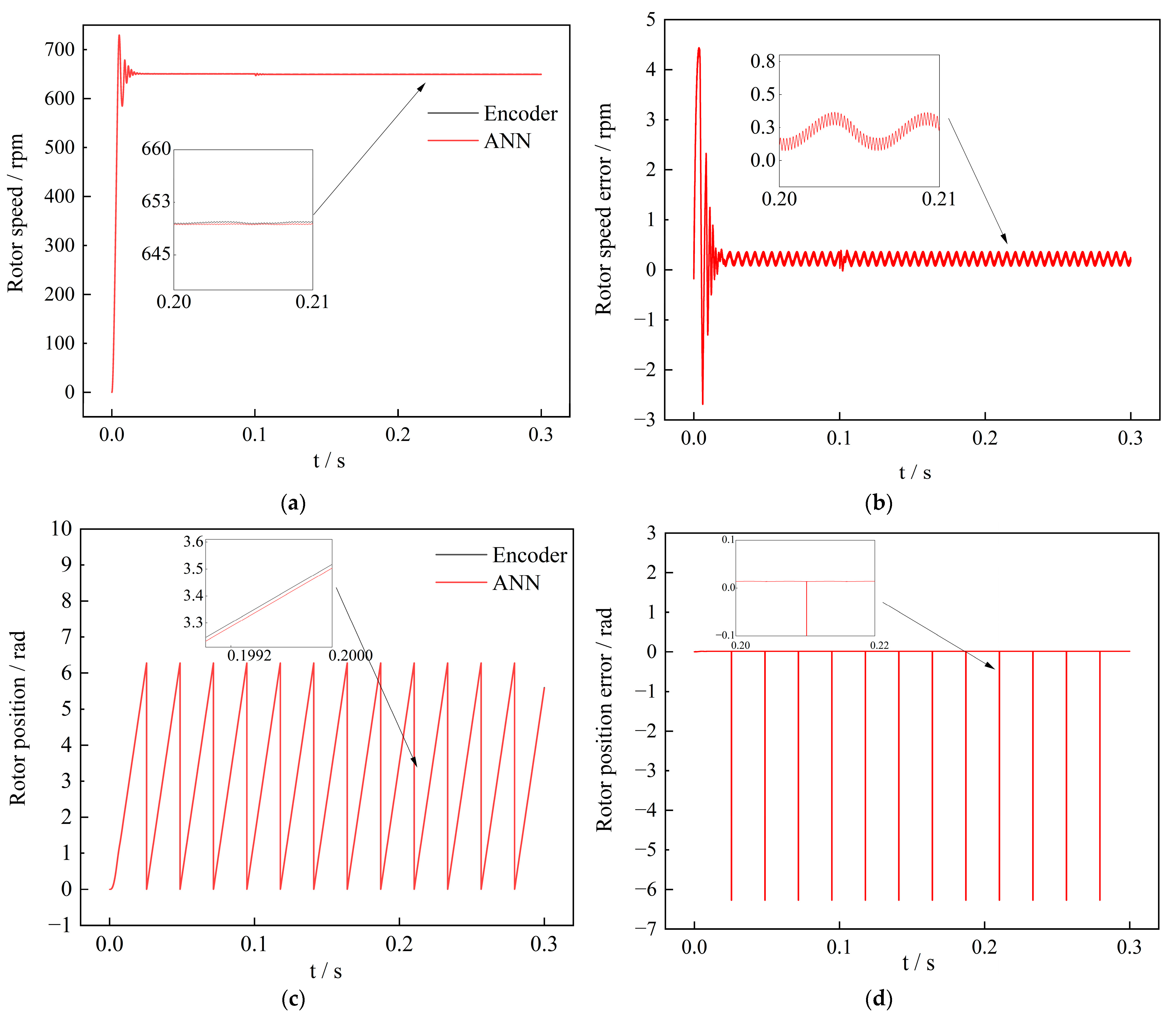
Condition 2: Given a motor with a moderate speed of 650 rpm, when t = 0.1 s, the load suddenly changes from 0 to 1 N·m, and the experimental results are shown in Figure 11. When the motor is suddenly loaded, the torque disturbance and speed fluctuation of the motor using the ANN algorithm are smaller, and its robustness and anti-interference performance are stronger. The maximum speed error estimated by the ANN algorithm is 0.4 rpm, and the maximum rotor error estimated by the ANN algorithm is 0.015 rad.
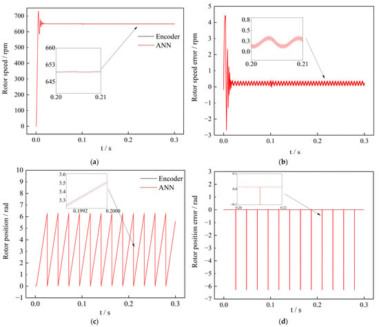
Figure 11.
Experimental results of brushless DC motor under different control loads. (a) Experimental speed diagram; (b) Experimental speed error diagram; (c) Experimental rotor position diagram; (d) Experimental rotor position error diagram.
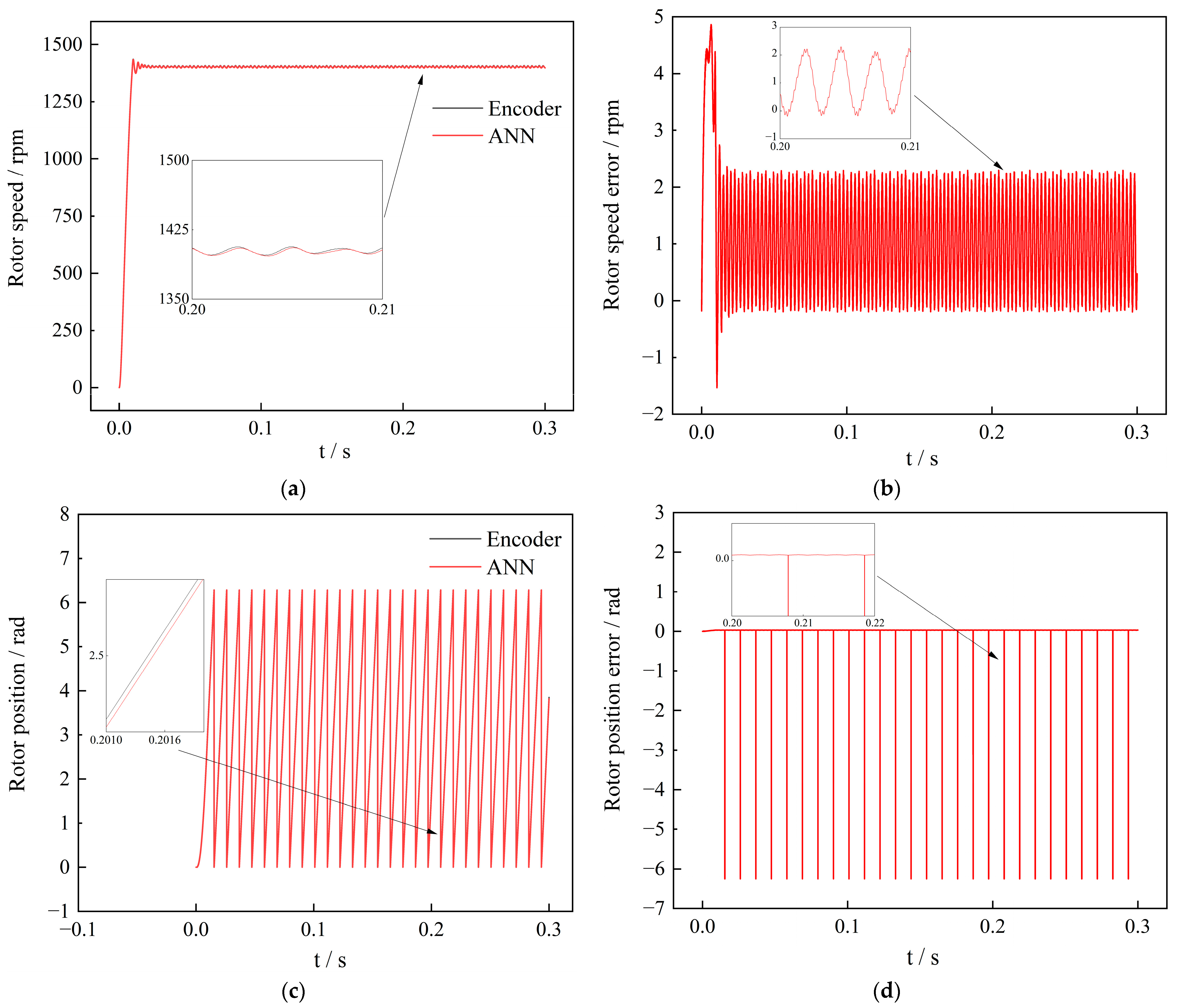
Condition 3: the motor is high speed at 1400 rpm with no load, and the experimental results are shown in Figure 12. The ANN algorithm with fast dynamic response performance can track the motor rotor in real time, which has excellent rotor-estimation accuracy. The maximum speed error is 2.3 rpm, and the maximum rotor position error is 0.02 rad. The feasibility of the proposed ANN algorithm has been verified through experiments.
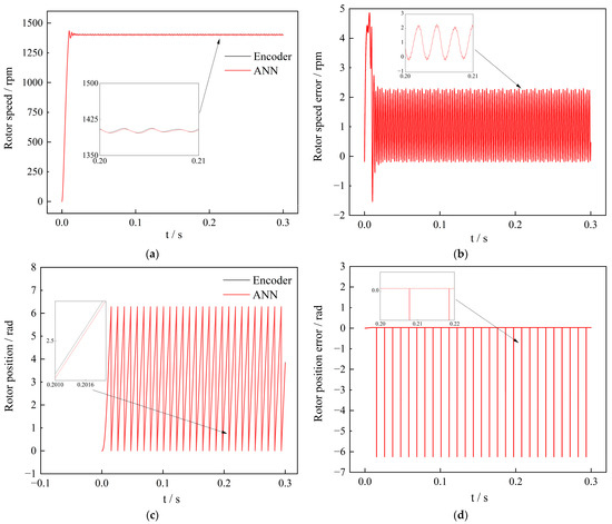
Figure 12.
Experimental results of brushless DC motor under different control at high speed and no load. (a) Experimental speed diagram; (b) Experimental speed error diagram; (c) Experimental rotor position diagram; (d) Experimental rotor position error diagram.
In addition, in the full speed range of 120~1600 rpm, the data measured by the encoder are compared with the ANN algorithm to obtain the MAE of the position and speed. Table 7 summarizes the performance results in different motor speed ranges. The position MAE is less than 0.02 rad and the speed MAE is less than 4 rpm.

Table 7.
Position speed MAE in different speed ranges.
5. Result Discussion
Below, the proposed method is compared with relevant research work to evaluate the performance of the proposed method in this article. During the research process, consider that the testing conditions are similar to those in this experiment as much as possible, and the specific results are shown in Table 8.

Table 8.
Comparison performance of the present work to the related research.
In summary, the method proposed in this article significantly improves the estimation performance of motor rotor position and speed. Timely and accurate rotor information improves the real-time performance of motor control, resulting in the fast dynamic response and high control accuracy of the system, enabling high-performance control of the motor.
6. Conclusions
In this paper, a neural network algorithm based on multi-layer perceptron (MLP) topology is proposed to estimate the rotor position and speed of brushless motors. The algorithm uses the motor phase voltage as the data sample to learn, train and test the neural network. For the proposed neural-network-estimation algorithm, the following conclusions are drawn from the above analysis:
- (1)
- The algorithm uses simple computing resources, allows implementation in low-cost circuit control systems, and only requires basic signal processing to achieve high signal-to-noise ratio feature synthesis.
- (2)
- The proposed ANN algorithm innovatively regards the motor phase transition as a virtual extended sequence number, which greatly improves the resolution accuracy of the ANN algorithm.
- (3)
- The experiment verifies the stability of the algorithm under different working conditions, the maximum motor speed error is 4 rp, and the maximum motor rotor position error is 0.02 rad. Compared with other traditional motor sensorless control algorithms, the algorithm greatly improves the estimation performance of the motor rotor and proves the effectiveness and progressiveness of the proposed ANN algorithm, which can be extended to other motor control systems.
- (4)
- This method is based on traditional control methods to obtain data samples for ANN learning and training. Compared to current advanced algorithms, the dynamic response performance of the proposed method is not superior enough. If advanced control algorithms are used as the basis for ANN improvement, the obtained motor control algorithm error will be smaller, and the control performance will be superior.
Author Contributions
Conceptualization, G.Y. and G.W.; methodology, S.H.; software, J.F.; validation, G.Y., G.W. and S.H.; formal analysis, J.F.; investigation, J.F.; resources, J.F.; data curation, J.F.; writing—original draft preparation, J.F.; writing—review and editing, G.Y.; visualization, J.F.; supervision, S.H.; project administration, G.Y.; funding acquisition, G.Y. All authors have read and agreed to the published version of the manuscript.
Funding
This work is supported in part by the National Natural Science Foundation of China under Grant 52066008, Development of domestic electronic control system (ECU) for China VI diesel engine under Grant 202104BN050007, Key technology research and development of methanol/diesel dual fuel engine under Grant 202103AA080002, Research and application of key technologies for extended-range commercial electric vehicles under Grant 202102AC080004.
Data Availability Statement
Data available on request from the authors.
Conflicts of Interest
The authors declare no conflict of interest.
References
- Vanchinathan, K.; Valluvan, K. A Study of Sensorless BLDC Motor Drives and Future Trends. Asian J. Res. Soc. Sci. Humanit. 2016, 6, 1863. [Google Scholar] [CrossRef]
- Kim, D.; Lee, K.; Kwon, B. Commutation torque ripple reduction in a position sensorless brushless dc motor drive. IEEE Trans. Power Electron. 2006, 21, 1762–1768. [Google Scholar] [CrossRef]
- Celikel, R. ANN based angle tracking technique for shaft resolver. Meas. Int. Meas. Confed. 2019, 148, 106910. [Google Scholar] [CrossRef]
- Matsui, N.; Shigyo, M. Brushless dc Motor Control without Position and Speed Sensors. IEEE Trans. Ind. Appl. 2012, 28, 120–127. [Google Scholar] [CrossRef]
- Jia, Z.; Zhang, Q.; Wang, D. A Sensorless Control Algorithm for the Circular Winding Brushless DC Motor Based on Phase Voltages and DC Current Detection. IEEE Trans. Ind. Electron. 2021, 68, 9174–9184. [Google Scholar] [CrossRef]
- Shrutika, C.; Matani, S.; Chaudhuri, S.; Gupta, A.; Gupta, S.; Singh, N. Back-EMF estimation based sensorless control of Brushless DC motor. In Proceedings of the 2021 1st International Conference on Power Electronics and Energy (ICPEE), Bhubaneswar, India, 2–3 January 2021; pp. 1–6. [Google Scholar]
- Ogasawara, S.; Akagi, H. An Approach to Position Sensorless Drive for Brushless DC Motors. IEEE Trans. Ind. Appl. 1990, 27, 443–447. [Google Scholar]
- Lee, W.; Sul, K. A new starting method of BLDC motors without position sensor. IEEE Trans. Ind. Appl. 2006, 42, 1532–1538. [Google Scholar] [CrossRef]
- Wang, Z.; He, Y. A New Initial Rotor Angle Position Estimation Method for High-speed Brushless Direct Current Motor Using Current Injection and Mathematical Model. J. Dyn. Sys. Meas. Control. 2018, 140, 71001–71007. [Google Scholar] [CrossRef]
- Thakar, D.; Patel, R. Comparison of Advance and Conventional Motors for Electric Vehicle Application. In Proceedings of the 2019 3rd International Conference on Recent Developments in Control, Automation & Power Engineering (RDCAPE), Noida, India, 10–11 October 2019; pp. 137–142. [Google Scholar]
- Bose, B. Neural network applications in power electronics and motor drives-An introduction and perspective. IEEE Trans. Ind. Electron. 2007, 54, 14–33. [Google Scholar] [CrossRef]
- Xiao, B.; Lam, K.; Tanaka, K.; Mendel, M. Guest Editorial: Special Issue on Type-2 Fuzzy-ModelBased Control and Its Applications. IEEE Trans. Fuzzy Syst. 2021, 29, 199–202. [Google Scholar] [CrossRef]
- Aydogmus, Z.; Aydogmus, O. A comparison of artificial neural network and extended Kalman filter based sensorless speed estimation. Meas. J. Int. Meas. Confed. 2015, 63, 152–158. [Google Scholar] [CrossRef]
- He, Y.; Zheng, S.; Fang, J. Start-up Current Adaptive Control for Sensorless High-speed Brushless DC Motors Based on Inverse System Method and Internal Mode Controller. Aeronautics 2017, 30, 358–367. [Google Scholar] [CrossRef]
- Ejlali, A.; Soleimani, J. Sensorless Vector Control of 3-phase BLDC Motor Using a Novel Extended Kalman. In Proceedings of the 2021 International Conference on Advances in Power Conversion and Energy Technologies (APCET), Mylavaram, India, 2–4 August 2012; pp. 1–6. [Google Scholar]
- Sabanci, K. Artificial intelligence based power consumption estimation of two phase brushless DC motor according to FEA parametric simulation. Meas. Int. Meas. Confed. 2020, 155, 107553. [Google Scholar] [CrossRef]
- Shifat, T.; Hur, J. ANN Assisted Multi Sensor Information Fusion for BLDC Motor Fault Diagnosis. IEEE Access 2021, 9, 9429–9441. [Google Scholar] [CrossRef]
- Shifat, T.; Wook, H. Remaining useful life estimation of BLDC motor considering voltage degradation and attention-based neural network. IEEE Access 2020, 8, 168414–168428. [Google Scholar] [CrossRef]
- Vieira, R.; Medeiros, C.; Silva, E. Classification and sensitivity analysis to detect fault in induction motors using an MLP network. In Proceedings of the 2016 International Joint Conference on Neural Networks (IJCNN), Vancouver, BC, Canada, 24–29 July 2016; pp. 796–802. [Google Scholar]
- Mamadapur, A.; Mahadev, G. Speed Control of BLDC Motor Using Neural Network Controller and PID Controller. In Proceedings of the 2019 2nd International Conference on Power and Embedded Drive Control (ICPEDC), Chennai, India, 21–23 August 2019; pp. 146–151. [Google Scholar]
- Gobinath, S.; Madheswaran, M. Deep perceptron neural network with fuzzy PID controller for speed control and stability analysis of BLDC motor. Soft Comput. 2020, 24, 10161–10180. [Google Scholar] [CrossRef]
- Jin, H.; Liu, G.; Zheng, S. Commutation Error Closed-Loop Correction Method for Sensorless BLDC Motor Using Hardware-Based Floating Phase Back-EMF Integration. IEEE Trans. Ind. Inform. 2022, 18, 3978–3986. [Google Scholar] [CrossRef]
- Shao, J.; Nolan, D.; Hopkins, T. A novel direct back EMF detection for sensorless brushless DC (BLDC) motor drives. In Proceedings of the APEC. Seventeenth Annual IEEE Applied Power Electronics Conference and Exposition (Cat. No.02CH37335), Dallas, TX, USA, 10–14 March 2002; pp. 33–37. [Google Scholar]
- Choudhary, T. Convolutional neural network based bearing fault diagnosis of rotating machine using thermal images. Measurement 2021, 176, 109196. [Google Scholar] [CrossRef]
- Tsotoulidis, S.; Safacas, A. A sensorless commutation technique of a brushless DC motor drive system using two terminal voltages in respect to a virtual neutral potential. In Proceedings of the 2012 20th International Conference on Electrical Machines, Marseille, France, 2–5 September 2012; pp. 830–836. [Google Scholar]
- Gan, M.; Zhang, M.; Zheng, C.; Chen, J. An adaptive sliding mode observer over wide speed range for sensorless control of a brushless DC motor. Control Eng. Pract. 2018, 77, 52–62. [Google Scholar] [CrossRef]
- Lu, Q.; Quan, L.; Zhu, X.; Zuo, Y.; Wu, W. Improved sliding mode observer for position sensorless open-winding permanent magnet brushless motor drives. Prog. Electromagn. Res. 2019, 77, 147–156. [Google Scholar] [CrossRef]
- Alex, S.; Daniel, A. An efficient position tracking smoothing algorithm for sensorless operation of brushless DC motor drives. Model. Simul. Eng. 2018, 2018, 4523416. [Google Scholar] [CrossRef]
- Carlos Gamazo Real, J.; Jaime Gomez, G. Sensorless detection of position and speed in brushless DC motors using the derivative of terminal phase voltages technique with a simple and versatile motor driver implementation. Electr Eng. Technol. 2015, 10, 1540–1551. [Google Scholar] [CrossRef]
- Guo, H.; Sagawa, S.; Ichinokura, O. Position sensorless driving of BLDCM using neural networks. Electr. Eng. Jpn. 2008, 162, 64–71. [Google Scholar] [CrossRef]
Disclaimer/Publisher’s Note: The statements, opinions and data contained in all publications are solely those of the individual author(s) and contributor(s) and not of MDPI and/or the editor(s). MDPI and/or the editor(s) disclaim responsibility for any injury to people or property resulting from any ideas, methods, instructions or products referred to in the content. |
© 2023 by the authors. Licensee MDPI, Basel, Switzerland. This article is an open access article distributed under the terms and conditions of the Creative Commons Attribution (CC BY) license (https://creativecommons.org/licenses/by/4.0/).

