Abstract
Over the past decade, there has been significant and rapid developments in organic-inorganic hybrid perovskite solar cells (PVSCs). Despite the fact that the power conversion efficiency (PCE) of PVSCs has increased from 3.8% to 25.8%, approaching that of commercial single crystalline Si solar cells, the market is still dominated by Si-based photovoltaic (PV) technology. This can be attributed to the challenges associated with upscaling PVSCs, improving device stability, and reducing the toxicity of PVSCs, which are hurdles in commercializing perovskite PV technologies. In particular, the toxicity due to lead leakage of PVSCs makes it difficult for them to enter the market. Hence, in this article, the structure and working principle of PVSCs are first summarized. Then, the toxicity of PVSCs is discussed, including the impacts of organic solvents and perovskite precursor materials on the health and environment. In this section, examples of advanced strategies for reducing the toxicity of PVSCs are also provided. Finally, challenges and a perspective for developing nontoxic PVSCs are given.
1. Introduction
With the rapid development of the world economy, the demand for electricity in various forms is on the rise all over the world [1]. However, the issues brought by traditional fossil energy, such as resource depletion and environmental damage [2], have become increasingly severe. Therefore, developing technologies to use renewable energy as an alternative power source is a growing tendency and has attracted tremendous attention from researchers. Among these technologies, solar cells based on the well-known photovoltaic (PV) effect, which can utilize clean and pollution-free solar energy with high efficiency, are considered one of the most promising technologies. Recently, the perovskite solar cells (PVSCs) have emerged as the most promising PV technology due to various advantages, such as high absorption coefficient, bandgap tunability, long carrier lifetime, and low recombination rate, which contribute to their high-power conversion efficiency (PCE) [3]. In fact, the world record PCE of PVSCs has reached 25.8%, approaching that of the single crystalline Si solar cells [4]. Moreover, the superb property that bandgap can be tuned within the range of 1.3 to over 3.0 eV via composition engineering has made PVSC the most promising material in the tandem solar cells and building integrated photovoltaics (BIPV) devices [5,6,7]. Consequently, researchers are increasingly interested in developing and optimizing PVSCs to improve their performance and enable their widespread adoption as a clean and efficient alternative to traditional fossil energy sources.
Development of Perovskite Solar Cells (PVSCs)
As shown in Figure 1a, organic-inorganic metal halide perovskites have a crystal structure of ABX3 where the A site is occupied by organic or inorganic cations, such as methylammonium (MA+), formamidinium (FA+), and Caesium (Cs+); B site is occupied by metal cations, such as Pb2+ and Sn2+; and X site is occupied by halide anions, such as I−, Br−, and Cl−. As depicted in Figure 1b, the PVSCs have a sandwich structure with the perovskite active layer deposited between the electron transport layer (ETL) and hole transport layer (HTL). The specific ETL and HTL materials used in these architectures can vary depending on the application and the desired device performance. Some commonly used ETL materials include metal oxides, such as titanium dioxide (TiO2) [8], zinc oxide (ZnO) [9], and tin oxide (SnO2) [10], and organic materials, such as fullerene derivatives [11] and conjugated polymers [12]. On the other hand, common HTL materials used include organic small molecules, such as Spiro-OMeTAD (2,2′,7,7′-tetrakis(N,N-di-p-methoxyphenylamine)-9,9′-spirobifluorene) [13], and polymers, such as poly(3,4-ethylenedioxythiophene) polystyrene sulfonate (PEDOT:PSS) [14]. During device operation, the perovskite active layer absorbs the light under illumination and generates charge carriers. Then, the photo-generated electrons and holes are extracted by ETL and HTL, respectively. With a suitable energy level alignment between different layers, the charge carriers can be transported to the corresponding electrodes and form current through the outside circuit [15].
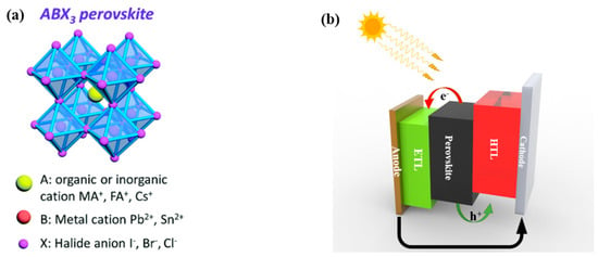
Figure 1.
(a) The crystal structure of perovskite materials. Reproduced with permission [16]. Copyright 2021, The Royal Society of Chemistry. (b) The device structure and working principle of the PVSCs.
The device architectures of PVSCs, as shown in Figure 2, include both mesoscopic and planar structures. The n-i-p mesoscopic device architecture, as depicted in Figure 2a, employs a mesoporous material (e.g., TiO2) as a scaffold that is deposited on the conductive glass substrate. Conversely, the n-i-p planar structure, as shown in Figure 2b, only comprises a planar layer on the substrate. Similarly, Figure 2c,d show the p-i-n planar and mesoscopic structures, respectively, with a p-type HTL deposited on the surface of a conductive glass substrate. The PVSCs with a planar structure are easy to fabricate, while the mesoscopic structure requires an additional step to form a mesoporous scaffold for perovskite deposition. However, it is hard to draw a conclusion regarding which structure is better, as PVSCs with both structures have achieved high efficiency exceeding 25% [17].
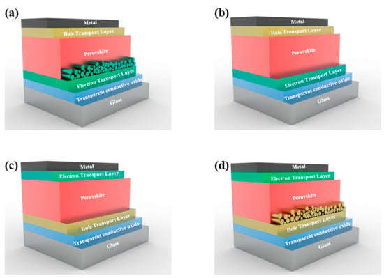
Figure 2.
(a,b) Device structures of mesoscopic and planar n-i-p PVSCs; and (c,d) represent the structure of p-i-n PVSCs.
In addition to their high efficiency in single-junction PVSCs, the tunability of the bandgap is one of the key features that make PVSCs a promising technology. As illustrated in Figure 3, PVSCs have potential applications in indoor PV, underwater PV, tandem PV, and BIPV. With suitable absorbance, wide-bandgap (WBG) perovskites can be used in indoor PVs that are typically powered by fluorescent lamps or white light-emitting diodes [18]. WBG perovskites with a bandgap of over 1.8 eV can also be used in underwater PVs, as they can absorb blue to yellow light [19]. In addition, WBG PVSCs have colorful appearances, making them attractive candidates for BIPVs [20]. They not only respond well to outdoor and indoor light but also provide aesthetic benefits due to their semitransparency and multiple color options. Furthermore, motivated by multijunction solar cells that combine semiconducting materials with different bandgaps, both narrow-bandgap and WBG perovskites have been explored in tandem PVs [21]. This approach allows the solar cell to capture a wider solar spectrum, increasing the overall device efficiency beyond the single-junction Shockley–Queisser limit [6]. Currently, the state-of-the-art perovskite/Si tandem PVs have achieved the highest PCE of 33.2%, showing the potential of perovskite-based PV technology [22].
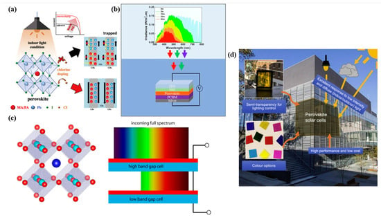
Figure 3.
Schematics of (a) indoor, (b) underwater, (c) tandem, and (d) semitransparent PVs based on PVSCs. Reproduced with permission [23]. Copyright 2020, Elsevier. Reproduced with permission [19]. Copyright 2022, Elsevier. Reproduced with permission [24]. Copyright 2022, Elsevier.
The formation of a high-quality perovskite film is also critical for achieving high-performance PVSCs. Figure 4a–h shows the main methods for PVSCs fabrication from small-area devices to large-area modules. For the small-area perovskite film deposition, spin coating is a commonly used method. Figure 4i shows both the one-step and two-step spin coating methods reported previously [25]. For the one-step process, the perovskite precursor materials are prepared in one solution, then spin-coated to form a film. While for the two-step process, the PbI2 layer is deposited on the substrate first, then the ammonium salt is coated on its top and reacts with PbI2 to form a perovskite layer. However, spin coating is only applicable for small area devices made in laboratories. To scale up the perovskite PV devices, as shown in Figure 4b–h, other methods, such as blade coating [26,27], slot-die coating [28,29], spray coating [30], dip coating [31,32], evaporation [33,34,35,36], chemical vapor deposition(CVD) coating [37], and screen-printing [38], have been applied for device fabrication. These methods can overcome the coating size limitation of spin coating, but controlling the morphology of the perovskite films is more challenging and thus requires further improvement for the development of PVSCs [27].
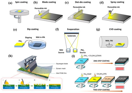
Figure 4.
Illustration of (a) spin coating, (b) blade-coating, (c) slot-die coating, (d) spray coating, (e) dip coating, (f) evaporation method, (g) CVD coating for perovskite films deposition. Reproduced with permission [26]. Copyright 2022, John Wiley and Sons. (h) Illustration of the screen-printing method for perovskite film deposition, where a wet perovskite film will be obtained by a sequence of operations, including prefilling, pressing, lifting, and flatting. Reproduced with permission [38]. Copyright 2022, Springer Nature. (i) Illustration of the one-step and two-step spin-coating methods for the deposition of CH3NH3PbI3 films. Reproduced with permission [25].
To sum up, it is noticeable from Figure 5 that over the past decade, the PVSCs have experienced significant development in efficiency in comparison with Si-based PV technology. This progress can be attributed to the research achievements in different perovskite materials, device architectures, and fabrication methods [3]. However, the commercialization of perovskite PV technology is still hampered by several issues, such as upscaling perovskite thin-film fabrication processing, improving the lifetime of perovskite PV devices, and reducing the toxicity of perovskite PV technology caused by the use of organic solvents and the toxic Pb during the device fabrication [39,40,41]. Additionally, the metal halide perovskite materials tend to degrade during the operation of PVSCs, and thus the toxic Pb2+ may enter the surrounding soil and water systems, consequently impacting human health. Therefore, this article focuses on the toxicity of PVSCs and elaborates on the environmental and health concerns arising from the use of solvents and perovskite precursor materials. Furthermore, this work overview advanced strategies for reducing the toxicity of PVSCs, specifically with regard to solvents and Pb materials. Finally, the potential and challenges of developing nontoxic PVSCs have been discussed in detail.
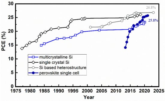
Figure 5.
The development of PVSCs in comparison with Si-based solar cells. The data points are extracted from the National Renewable Energy Laboratory (NREL) Best Research-Cell Efficiency Chart [22].
2. Toxicity Due to Organic Solvents
2.1. Origin and Hazards of the Toxicity
The utilization of organic solvents in the fabrication process of PVSCs is a significant source of toxicity of this technology. These solvents are crucial for dissolving and coordinating with precursor materials during the fabrication process. However, as illustrated in Figure 6a, most of the high-efficiency PVSCs reported to date have been fabricated using volatile organic solvents with high toxicity [42,43,44,45,46,47,48]. The solvents utilized in the fabrication of PVSCs can be summarized into precursor solvents, antisolvents, and solvents for the ETL/HTL, most of which are toxic and thus represent a significant obstacle to the upscaling implementation of PVSC technology.
Generally, the precursor solvents are used to dissolve perovskite materials and are subsequently deposited to form polycrystalline films upon thermal annealing. However, the most commonly used solvents, such as N,N-dimethylformamide (DMF), dimethyl sulfoxide (DMSO), and γ-butyrolactone (GBL), are known to be hazardous to human health and the environment. Although DMSO is generally regarded as less toxic, a mixture of DMF and DMSO has gained popularity in perovskite precursor solutions to enhance the morphology of perovskite films [49]. Specifically, DMF is used to improve the dissolution of PbI2, while DMSO coordinates with Pb2+ [50,51]. Therefore, the use of DMF in the fabrication process is necessary, despite its well-known toxicity.
DMF is considered the most toxic substance among all the solvents used in the fabrication process of PVSCs [52]. In the European Union, the concentration of DMF in PVSCs has been restricted to <0.3% to limit its potential harm to the environment and human health [40,53,54]. More dangerously, exposure to DMF through inhalation or skin contact may pose a potential risk to workers, as it is easily absorbed by the skin and can cause adverse health effects such as liver damage, skin irritation, anxiety, palpitations, headache, flushing, nausea, and vomiting [55,56]. Therefore, it is essential to explore alternative solvents or methods that can reduce or eliminate the use of DMF in the fabrication of PVSCs.
Antisolvents are commonly used to assist the nucleation and crystallization of perovskite films by quickly removing the host solvent [57]. However, it is noteworthy that the universally used antisolvents, such as chlorobenzene (CB) and toluene, are highly toxic and volatile. CB is a hazardous chemical that is known to be toxic to aquatic organisms, and it may have long-term adverse effects on the aquatic environment. Several studies have reported that CB poses a significant risk to aquatic life due to its persistence, bioaccumulation, and toxic properties [58]. More dangerously, exposure to CB can lead to a range of health effects in humans, including exhaustion, nausea, lethargy, headache, and irritation to the upper respiratory tract and eyes [59]. Furthermore, CB has been linked to several reported carcinogenic effects, making it a serious environmental and health concern [60]. Toluene poses significant health and environmental risks. Toluene is a volatile organic compound that can easily contaminate crops, vegetation, aquatic life, and soil fertility [61]. Exposure to toluene can lead to a range of severe health effects, including neurological, respiratory, skin, and eye damage [62]. Toluene is a known neurotoxicant, and exposure to high levels can result in headaches, dizziness, confusion, and memory loss [63]. In addition, chronic exposure to toluene has been linked to developmental abnormalities and reproductive toxicity in humans and animals [61].
In the fabrication of PVSCs, ETLs, and HTLs are critical components that perform a significant role in facilitating efficient charge transfer and collection. For the preparation of ETL and HTL, the selection of solvents can greatly impact the quality and performance of these layers [64]. For the preparation of ETLs, solvents, such as CB, dichlorobenzene (DCB), and GBL, are commonly used [65,66]. For HTLs, Spiro-OMeTAD is the most widely used HTL in n-i-p structure PVSCs. However, this material can only be dissolved in solvents, such as 2-methoxyethanol (2-ME), DMSO, DCB, toluene, and isopropanol [67,68]. These solvents have also been identified as toxic and harmful to the environment and human health, with isopropanol being a potential irritant to the respiratory tract, eyes, and skin [69,70,71].
The toxicity of the aforementioned polar non-protonic solvents for perovskites has been documented by the European Chemical Agency (ECHA), as they are listed as Substances of Very High Concern (SVHC) [72,73]. Ding et al. conducted an analysis of ten commonly used solvents with regard to their toxicity to the ecosystem, workers, and the general population [74]. Based on device performance, the solvents were classified into four categories: most widely used, high industry potential, low industry potential, and high toxicity. Figure 6b presents the results of this analysis. Notably, DMSO, ethanol, and isopropyl alcohol (IPA) are shown to have the least impact on the environment and human health while maintaining the desired device performance.
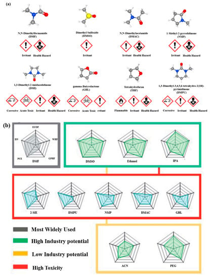
Figure 6.
(a) The mainly used solvents in the fabrication of PVSCs with their pictograms, where the blue balls represent nitrogen atoms, where yellow, red, white, and gray are sulfur, oxygen, hydrogen, and carbon atoms, respectively [75,76,77,78,79,80,81,82]. (b) A comprehensive evaluation of the DMF, DMSO, Ethanol, isopropyl alcohol (IPA), 2-methoxy ethanol (2-ME), DMPU, NMP, DMAC, and GBL through the comparison of their properties, including eco-toxicity factor (ECOF), workers hazard factor (WHF), general population hazard factor (GPHF), donor number (DN), and PCE. the larger the area enclosed, the better the solvent. Reproduced with permission [74]. Copyright 2022, Royal Society of Chemistry.
In order to comprehensively evaluate the impact of different stages in the production process on the environment, economy, and human health, Life cycle analysis (LCA) has been commonly used in various industries, such as the coal chemical industry and biomass power generation. Although some LCA or similar studies on PVSCs have been reported, the impact of solvents on the environment and human health in perovskite production is still unresolved [83].
Figure 7 provides the potential pathways for LCA of solvents used in perovskite production. All production pathways of solvents for the manufacturing of PVSCs involve a transport section and a solvent removal section during the drying and annealing of the thin film. These sections have the potential to emit hazardous materials to the environment. The latter sections vary in different stages of production. In the laboratory and pre-industrial stages, solvents are directly released into the environment. However, in the commercialization stage, the solvents may be condensed and either incinerated or reused to enhance energy efficiency, resulting in only a small fraction directly emitted. Another pathway in the commercialization stage involves distilling the condensed solvent and incinerating the fraction that is not distilled.
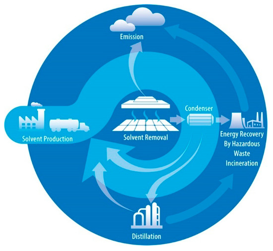
Figure 7.
The LCA system boundary schematic of perovskite photovoltaics. Four potential pathways in the LCA of solvents for the production of PVSCs. The sections, such as solvent production, solvent removal, incineration, and distillation, are illustrated. Reproduced with permission [40]. Copyright 2020, Springer Nature.
Hence, it is worth noting that the solvents used in perovskite production, especially the toxic and hazardous solvents, can have significant impacts on the environment and human health. Therefore, it is crucial to comprehensively assess the environmental and human impact of the solvents used in the fabrication of high-performance PVSCs. Although the harm of some solvents has been reported, the lack of a full LCA system to evaluate the impact of solvent toxicity on the environment and human health poses a significant challenge to the sustainable development of PVSCs. LCA can provide a useful tool to assess the potential impacts of these solvents in different production stages and to identify the most environmentally friendly and sustainable pathways for perovskite production. Future research should focus on conducting more comprehensive LCAs to evaluate the impact of solvents in perovskite production, and to develop more sustainable and environmentally friendly manufacturing processes for perovskite PV industry.
2.2. Strategies to Reduce the Toxicity
2.2.1. The “Green” Solvents
In the quest for more environmentally friendly and sustainable production of PVSCs, researchers have explored various alternatives to traditional solvents used in the fabrication process. Cui et al. have provided a comprehensive summary of the green antisolvents and green solvents for HTL/ETL [84]. Therefore, in this article, we will focus on the green solvents used as precursor solvents in the fabrication of PVSCs.
As DMF is known as the most toxic chemical in the solvent system, one effective strategy to reduce the harmful impact of DMF is finding alternative solvents that are less hazardous and nontoxic. To achieve this goal, it is vitally important to understand the relationship between various solvent systems, lead salts, and post-deposition treatments. Recently, several studies have successfully shed light on some of these factors [17,18,19]. Additionally, the search for “green solvents” with lower toxicity has been a focus of research in this area. The term “green solvents” can refer to solvents that have been modified with additives or solvent mixtures that can contribute to reducing toxicity during the fabrication of PVSCs [40]. The use of such green solvents can potentially reduce the overall environmental impact and promote sustainable development in the photovoltaic industry.
One such “green solvent” is ethyl acetate (EA), which has been utilized as an antisolvent for perovskite and solvent for the HTL to optimize the perovskite/HTM interface [67]. EA has also been employed in antisolvent treatments [85,86] and precursor solvents. Zhang [87] explored EA as additive in the precursor solution, followed by an EA antisolvent treatment to facilitate the quick removal of residual solvents and expedite the MAPbI3 perovskite crystallization process. The effects of the EA-modified precursor treatment on the perovskite film morphology were investigated and compared with the initial precursor treatment. As shown in Figure 8a, scanning electron microscopy (SEM) images revealed that the EA-modified perovskite film had a smooth, flat, and defect-free morphology with larger grain size compared to the initial precursor treatment. Furthermore, an optimized n-i-p mesoscopic FTO/TiO2/Perovskite/Spiro-OMeTAD/Ag device was fabricated using the EA-modified precursor treatment, which achieved a PCE of 19.53% with enhanced stability. These results demonstrated the potential of EA as a “green solvent” in the fabrication of high-performance and stable PVSCs.
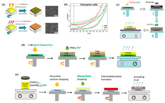
Figure 8.
(a) Schematic of perovskite film deposition using pristine perovskite precursor or EA-modified precursor with its corresponding top-view SEM images. Reproduced with permission [87]. Copyright 2022, Royal Society of Chemistry. (b) Photovoltaic characteristics for the champion PVSCs obtained with different solvents. The definitions of different solvents are below: DMF means the solvent is consisted of a molar ratio of 8.2 to 1 of DMF and DMSO; Similarly, the molar ratios of NMP and EA are DMF:NMP:DMSO = 4.1:4.1:1 and DMF:EA:DMSO = 5.74:2.46:1, respectively [88]. (c) An all green solvent system with only two green solvents, water and 2-propanol (IPA), to fabricate the CsPbBr3, where water serves to dissolve precursors of Pb(NO3)2 and CsBr, and IPA serves to dissolve phenethylammonium Bromide (PEABr). Reproduced with permission [89]. Copyright 2021, Royal Society of Chemistry. (d) Another anomalous route using all green solvents for the fabrication of CsPbBr3. With CsBr solution is first deposited in the first step, then reacted with PbBr2, a green solvent system of water, ethanol, ethylene glycol (EG), and triethyl phosphate (TEP) was used to solute CsBr and PbBr2. Reproduced with permission [90]. Copyright 2021, Royal Society of Chemistry. (e) Schematic diagram of a consecutive two step spin-coating fabrication procedures for all green solvent engineering approach. Reproduced with permission [50]. Copyright 2022, Elsevier.
To reduce the use of toxic DMF, Wang developed a solvent system composed of DMSO, 2-methylpyrazine, and 1-pentanol [91]. By optimizing the preparation conditions, a well-crystallized perovskite film with such a solvent system has been achieved, and the corresponding planar n-i-p PVSCs show a PCE of 16%, indicating the potential of such mixed solvent for perovskite fabrication.
In another study, Stancu investigated the partial replacement of DMF with less toxic N-methyl-2-Pyrrolidone (NMP) and EA [88]. The PV characteristics of the devices obtained with different solvents are shown in Figure 8b. Under the same deposition parameters, the partial replacements of NMP and EA demonstrated promising results in reducing the toxicity in the fabrication process.
Several all-green solvent systems have also been reported, which are environmentally friendly and have a lower toxicity. However, the device performance achieved with these systems is relatively low compared to conventional systems. As depicted in Figure 8c,d, Cheng [92] summarized two all-green solvent systems to fabricate all-inorganic CsPbBr3 films. Despite improving the device stability, the champion PCE is only 8.11%, which is less than the highest PCE of 10.45% among the all-inorganic CsPbBr3 PVSCs [93]. Another all-green solvent engineering approach for organic–inorganic hybrid perovskite layers was also reported by Cao [50]. They employed a green Lewis base solvent, triethyl phosphate (TEP), to prepare (FAPbI3)1−x(MAPbBr3)x (x = 0 or 0.05) films, followed by an antisolvent treatment with the non-polar solvent, dibutyl ether (DEE), as shown in Figure 8e. The resulting FTO/SnO2/Perovskite/Spiro-OMeTAD/Au device achieved a PCE of 18.65% (x = 0) and 20.13% (x = 0.05), which is the highest value for all-green solvent processed PVSCs.
In summary, replacing toxic solvents with green and nontoxic solvents is an important step towards sustainable and environmentally friendly PVSCs. While the use of green solvents can reduce toxicity, it has limited effectiveness as the device performance is relatively low [74]. Therefore, it is necessary to find a strategy that can keep a balance between toxicity and device efficiency.
2.2.2. Fabrication Methods without Solvent Treatment
While solvent treatment methods using less toxic alternatives have shown some promise, several techniques have been proposed that eliminate the need for solvents altogether.
Jones developed a solvent-free solid-state reaction method that employs the low-toxicity terpineol to form perovskite precursor ink [52]. As shown in Figure 9a–c, the X-ray powder diffraction results show the perovskites can be formed by such solvent-free solid-state reactions. The MAPbI3 perovskite film fabricated by bar casting using this ink showed enhanced stability compared to its counterpart fabricated by spin-coating, as shown in Figure 9d. However, maintaining compositional control during solid-state reactions is a challenging task.
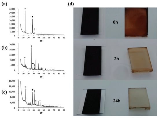
Figure 9.
XRD image of MAPbI3 films fabricated by (a) solution processing, (b) solid state reaction using TiO2, and (c) deposited on glass from a perovskite ink. Additionally, (d) a comparison of stability of MAPbI3 made by solid-state reaction and solution process [52].
Apart from the blade-coating method, thermal evaporation has also been explored as a viable nontoxic method to fabricate PVSCs. Li et al. have reported the successful fabrication of perovskite modules using a co-evaporation method, as shown in Figure 10a. By combining perovskite composition engineering and surface/interface engineering, the resulting perovskite module with an active area of 21 cm2 exhibited a PCE of 18.13%. This value is only slightly lower than the efficiency of the perovskite single cell (1 cm2) of 19%, indicating the potential of the thermal evaporation method for developing highly efficient large-area perovskite modules [94].

Figure 10.
(a) The PVSCs fabricated by Li et al., including their PCE and area. Reproduced with permission [94]. Copyright 2020, Elsevier. (b) FA1−yCsyPb(I1−xClx)3 perovskite thin films fabricated via simultaneous code position of four precursors and the current–voltage (J–V) curse of the x = 0 and 0.2 [33]. (c) Scheme presenting the Cl-containing alloy–mediated sequential vacuum deposition approach in Hang L’s work, where evaporated cesium iodide (CsI), lead iodide (PbI2), and lead chloride (PbCl2) create a composite precursor film on which formamidinium iodide (FAI) molecules were deposited under precise control [34].
Kilian B et al. demonstrated the improvement of growth and optoelectronic properties for vapor-deposited [CH(NH2)2]0.83Cs0.17PbI3 perovskite solar cells by partially substituting PbI2 for PbCl2 as the inorganic precursor [33]. The current density-voltage (J-V) for 0.25 cm2 devices with active layers deposited with and without PbCl2, as shown in Figure 10b, reveals a substantial increase in all J-V figures of merit for the devices with PbCl2. In fact, the champion device PCE improves from 16.4% for the neat iodide film to 19.3% for 20% PbCl2 substitution.
Hang L et al. have reported a Cl-containing alloy-mediated sequential vacuum evaporation approach to fabricate perovskite films, as illustrated in Figure 10c [34]. The resulting PVSCs yield a PCE of 24.42%, 23.44%, and 19.87% for 0.1, 1.0, and 14.4 square centimeters, respectively. These results demonstrate the potential of evaporation methods for fabricating efficient and large-area PVSCs.
In conclusion, the development of solvent-free methods for fabricating perovskite solar cells has shown promising results in terms of enhancing device stability and efficiency while eliminating the use of toxic solvents. Solid-state reactions and thermal evaporation methods have emerged as viable alternatives, with some studies achieving efficiencies close to those of conventional methods. However, challenges, such as maintaining compositional control and scalability, remain to be addressed. Future research should focus on improving the reproducibility and scalability of these methods while continuing to optimize device performance. Overall, the development of non-toxic and environmentally friendly methods for perovskite solar cell fabrication is a critical step towards sustainable energy production.
3. Toxicity due to Perovskite Materials: Pb
3.1. Origin and Hazards of the Toxicity
Lead (Pb) is a well-known, highly toxic element, and the use of Pb in PVSCs has raised concerns about the potential environmental and health hazards associated with its toxicity. In the PVSCs, the perovskite tends to decompose with exposure to environmental conditions, such as exposure to humidity, oxygen, elevated temperature, UV radiation, or a combination of these factors, resulting in the formation of harmful compounds containing heavy metals that can leak into the environment and impact living organisms [95].
Taking MAPbI3 as an example, the possible degradation pathways for perovskites are illustrated by the following (1)–(7) chemical reactions. Although reactions (1) and (2) are reversible, the perovskite material will slowly break down into its constituents and additional byproducts as the presence of oxygen and UV radiation further breaks down hydroiodic acid (HI), producing water (H2O), hydrogen (H2), and iodine (I2) gases as byproducts, as shown in reactions (3)–(7) [96]. Due to their ionic nature, degraded perovskites can be easily dissolved by water, potentially contaminating the soil, and groundwater, and impacting plants and other living organisms.
CH3NH3PbI3(s) ↔ PbI2(s) + CH3NH3I(aq)
CH3NH3I(aq) ↔ CH3NH2(aq) + HI(aq)
4HI(aq) + O2 ↔ 2I2 + 2H2O(l)
2HI(aq) ↔ H2(g) + I2(s)
CH3NH3PbI3(s) ↔ PbI2(s) + CH3NH2 ↑ + HI ↑
2I− ↔ I2 + 2e−
3CH3NH3+ ↔ 3CH3NH2↑ + 3H+
Although the Pb content per square meter of PVSCs is only a few hundred milligrams, the potential Pb exposure associated with the commercialization of perovskite PV devices should be treated cautiously [95]. The weight percentage of Pb in CH3NH3PbI3 perovskite is calculated as 33.4% by the equation of:
Given 1 m2 MAPbI3 perovskite with 500 nm thickness, the total weight of MAPbI3 perovskite is 4.16 g/cm3 × 1 m2 × 500 nm = 2.08 g. Therefore, the total weight of Pb in a 1 m2 MAPbI3 perovskite solar cell is 2.08 g × 33.4% = 0.69 g.
As shown in the above calculation, although there is only 0.69 g Pb in 1 m2 MAPbI3 perovskite solar cell, once the devices are damaged during rainfall, the toxic lead can leak out, then enter the soil and underground water, causing serious environmental, and health contamination.
In terms of the environment, the contamination of soil and water with Pb is permanent and can have a significant negative impact on human, animal, and plant survival [97]. Moreover, perovskite active layers in PVSCs are easily degraded and dissolved in water to generate toxic Pb2+, which can easily enter plants and, thus the food chain, ultimately impacting human health [95].
For humans, in the event of lead leakage, the predominant route of human exposure is through the consumption of drinking water or food contaminated by lead seepage into the soil. Therefore, there are regulatory guidelines in place for permissible lead concentrations in water, soil, and food. For instance, in China, the maximum allowable lead content in agricultural soil is limited to 250 mg/kg [98]. The gastrointestinal, respiratory, and dermal routes of exposure are the primary routes of Pb intake. The absorption, distribution, and excretion of Pb are illustrated in Figure 11, and the percentage of overall absorption is indicated for each route of intake [95]. Furthermore, the elimination of Pb from the body is difficult, as it is primarily deposited in the skeleton, with a total amount of 90% and a long half-life of 20 to 30 years [99,100]. Pb can impair the functionality of enzymes and receptors, interfere with haem activity, and gradually form insoluble lead phosphate in bones [95]. Pb can also be excreted through breast milk, making infants more susceptible to its harmful effects [101]. Symptoms associated with Pb exposure include neurological deficiencies, nausea, vomiting, abdominal pain, headaches, seizures, muscle weakness, genotoxicity, carcinogenicity, and reproductive defects [102,103,104,105]. In particular, the usage of toxic solvents, such as DMF and DMSO, increases the bioavailability of Pb, thereby increasing the risk of absorption by dermal contact and oral ingestion, making frontline workers more vulnerable to infection [106].
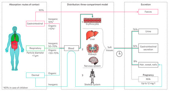
Figure 11.
Schematic overview of absorption, distribution, and excretion of Pb compounds in the human body. Reproduced with permission [95]. Copyright 2019, Springer Nature.
3.2. Strategies to Reduce the Toxicity
3.2.1. Lead-Free Perovskite
To mitigate the toxicity of Pb in PVSCs, nontoxic elements, such as Sn, Bi, Ge, Sb, Mn, and Cu have been proposed as alternative candidates to replace Pb in ABX3 perovskite structures [107]. Although some of these elements are toxic to some degree, the current perovskite PV community generally holds the view that these elements are nontoxic alternatives in PVSCs. Hence, massive research has been devoted to these substitutions, which not only increase the diversity of perovskite species but enhance the environmental sustainability of PVSCs. Nevertheless, lead-free perovskite devices still require further improvements.
Among the various approaches to reduce the toxicity of Pb, lead-free perovskite is currently one of the hottest research areas, which has increased the diversity of perovskite materials. Figure 12a displays the elements that have been theoretically predicted to substitute Pb in perovskite structures [108]. However, the current efficiency of PVSCs based on lead-free perovskites is still below 15%, as shown in Figure 12d [107].
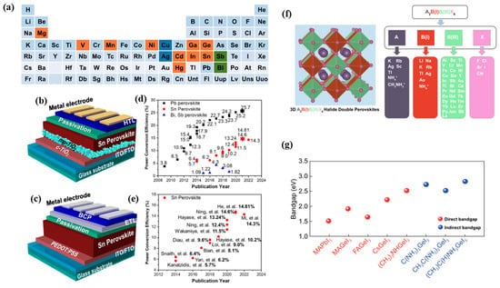
Figure 12.
(a) Potential elements to substitute Pb, which are labeled as orange, green, and blue [107]. (b) n-i-p and (c) p-i-n structures of Sn-based perovskite solar cells. (d) Reported PCE of Pb, Bi, and Sn-based PSCs. (e) Evolution of the PCE of Sn-PVSCs [109]. (f) Crystal structure of double perovskite A2BB’X6 and the elements/functional groups that can form double perovskite A2BB’X6 [107]. (g) Bandgaps of various Ge-based perovskite materials compared with MAPbI3. Reproduced with permission. [110] Copyright 2019, The Royal Society of Chemistry.
Among the lead-free perovskites, the Sn-based perovskites have gained much attention due to their high-performance potential [53]. The Sn-based perovskite structures are depicted in Figure 12b,c, and they have been reported to have a certified PCE of up to 14.8%, which is the highest among reported lead-free devices (Figure 12e) [111]. However, the instability caused by the easy oxidation of the Sn remains a major hurdle in the development of Sn-based perovskites. To address this issue, Hoshi [3] proposed the use of additives to improve the stability of Sn-based devices. While significant improvement was observed, the efficiencies of these devices were very low compared to Pb-based devices. Another strategy for surmounting the poor stability of Sn-based PVSCs is the use of double perovskites, which are depicted in Figure 12f. In such a structure, nontoxic monovalent (B) and trivalent (B′) metal cations neutralize the overall charge of the perovskite lattice.
Apart from Sn, Ge-based perovskites have also emerged as a promising alternative to Pb-based perovskite due to their low toxicity [112]. Among the main Ge-based perovskites, MAGeI3, CsGeI3, and FAGeI3 have been studied [113]. By altering the A-site cations, the bandgap of Ge-based perovskites can be tuned to close to the conventional lead halide perovskite of 1.5 eV, as depicted in Figure 12g. Generally, Ge-based perovskites exhibit different energy structures than Pb-based ones, so optimizing suitable ETL and HTL is crucial to improve the charge extraction efficiency in the device. However, current Ge-based devices suffer from low PCE of less than 1% and stability issues similar to those observed in Sn-based perovskites, making the future of Ge-based devices appear bleak.
Other elements, such as Bismuth (Bi), antimony (Sb) [114,115], and Divalent transition metal cations (e.g., Cu2+, Fe2+, Zn2+) [116], have also been considered as potential candidates for Pb-free perovskites. All of these elements can be used to tune the photovoltaic properties via various routes. However, it is essential to acknowledge that while lead-free alternatives for PVSCs have been developed, these alternative elements may still pose a certain degree of toxicity and pose risks to human health and the environment. Although the perovskite community generally considers these elements to be non-toxic and eco-friendly, it is critical to conduct a comprehensive LCA of these lead-free perovskite solar cells to determine their overall environmental impact.
3.2.2. Pb Recycling Technologies
According to the International Lead Association, Pb is known to be one of the most effectively recycled materials globally [95]. Therefore, to reduce the detrimental impact on the environment, sustainable recycling technologies at the end of PVSC life have become necessary for the commercialization of PVSCs. The main methods for dealing with these issues include selective Pb extraction recycling and in situ Pb recycling processes, as summarized in Figure 13a,b.
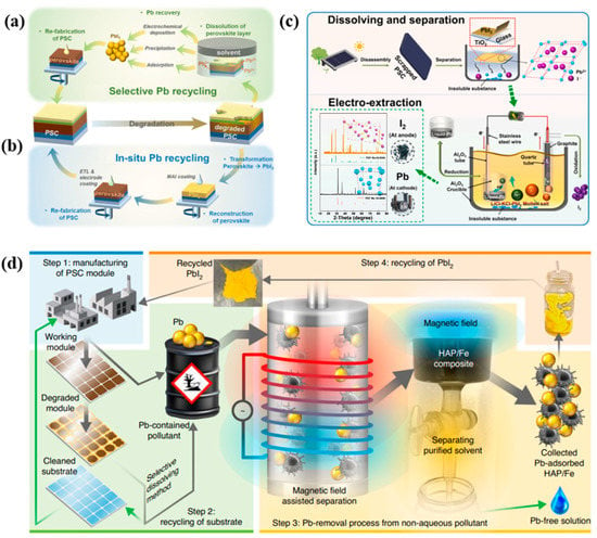
Figure 13.
Illustration of Pb recycling technologies through two different approaches of (a) selective Pb recycling and (b) in situ Pb recycling processes [109]. (c) Schematic diagram of the electrochemical recovery of Pb and I2 from PVSCs in molten LiCl-KCl. Reproduced with permission [117]. Copyright 2022, Elsevier. (d) Process of Pb removal/separation from Pb-containing pollutant formed during manufacturing and recycling of PVSCs. The grey arrow represents a Pb-containing process, and the green arrow represents a Pb-free process. Reproduced with permission [113]. Copyright 2020, Springer Nature.
The selective Pb recycling process involves the dissolution of the perovskite materials in solvents, followed by the subsequent collection of lead from the resulting solution. The collected Pb can be reused in the fabrication of PVSCs, but a small loss in PCE may occur. The collection step mainly includes electrochemical deposition, precipitation, and adsorption processes. As illustrated in Figure 13c, electrochemical deposition involves the dissolution of perovskites in deep eutectic solvents (DES) [118] or molten LiCl-KCl(eutectic composition) [117] to form a mixed solvent. Subsequently, the Pb and I2 are deposited at the cathode and graphite anode, respectively. Although a recovery rate of 100% can be achieved by electrochemical deposition [118], it is challenging to control the complex electrodeposition conditions required to obtain the desired Pb layer. Moreover, additional steps are needed to recycle Pb to PbI2, which serves as a precursor for PVSCs.
In order to achieve a more convenient recycling of Pb, the precipitation of PbI2 after dissolving the perovskite layer has been implemented. Polar aprotic solvents, such as DMF, GBL, and DMSO have been reported to be widely used to recycle PbI2 in degraded PVSCs [109]. However, since the dissolution of HTMs also occurs in the first step, significant efforts have been made to improve the PCE of the recycled PVSCs using this method. Furthermore, in order to address the toxicity issues associated with the aforementioned solvents, less hazardous solvents have also been explored [119].
As a sustainable and environmentally friendly recycling of PbI2 from PVSCs, using adsorbents that offers a high recovery rate and purity has been studied. Hydroxyapatite (HAP, Ca10(PO4)6(OH)2) has been used as an adsorbent in the recycling process, as it exhibits a high adsorption efficiency of 99.99% from Pb-containing solvents such as DMF. More recently, a Fe-decorated HAP (HAP/Fe) was employed for complete Pb management, achieving a 99.99% adsorption efficiency of dissolved Pb2+ ions in DMF, as shown in Figure 13d. Recycled PVSCs using HAP/Fe showed a PCE of 16.04%, which was similar to the PCE of fresh PVSCs at 16.65%.
Another selective recovery method that offers a nontoxic and simple approach is ion exchange. Wang [53] reported a “one-key-reset” strategy for recycling PVSCs, as depicted in Figure 14a. The PCE of recycled PVSCs was 20.08%, which was only slightly lower than the PCE of fresh PVSCs at 20.65%, even after being recycled twice. This method offers a sustainable approach to the recycling of PVSCs and paves the way for the commercialization of this technology.
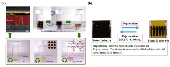
Figure 14.
(a) Schematic illustration of the “one-key reset” recycling process, which involves treating the entire device with a chemical solution to dissolve and separate the perovskite material from other components. The remaining components, such as the electrode and substrate, are then cleaned and can be reused to fabricate new PVSCs. Reproduced with permission [120] Copyright 2021, Elsevier. (b) Degradation and rejuvenation process during the device’s lifetime. Reproduced with permission [121] Copyright 2016, The Royal Society of Chemistry.
As depicted in Figure 13b, in situ Pb recycling technologies aim to restore the degraded perovskite layer to its initial state. This method has the potential to reduce production costs by reusing materials. One rejuvenation strategy in hydroiodic involves immersing the entire PVSC in a methyl ammonium iodide (MAI) solution. As shown in Figure 14b, Huang et al. [121] prepared an ITO/ZnO/perovskite/Spiro-OMe TAD/Au device that was rejuvenated after 60 days using an MAI-assisted rejuvenation approach. The results showed that after the second rejuvenation process, the device had a PCE of 11.4% compared to 11.6% in its initial state.
Other in situ Pb recycling technologies have also been proposed [122,123]. These in situ recycling processes can minimize refabrication costs and time while reducing toxic Pb loss. However, as the number of rejuvenation cycles increases, the rejuvenate effect gradually decreases, which limits the ability to rejuvenate PVSCs. Moreover, in practical commercial scenarios, it is important to consider that perovskite materials are susceptible to degradation and potential leakage when exposed to outdoor environments. This poses a significant challenge for the implementation of in situ Pb recycling technologies, as the effectiveness of these methods can be greatly diminished by such degradation and leakage. Therefore, it is necessary to develop and employ protective measures and strategies to mitigate these issues and ensure the practicality and viability of in situ Pb recycling in commercial settings.
3.2.3. Device Encapsulation to Prevent the Pb Leakage
Encapsulation is considered the most promising strategy for mitigating the risk of Pb and other toxic material leakage caused by the degradation of PVSCs. External encapsulation involves the use of a layer of physical or chemical barriers, such as lead-trapping materials or chemical barriers, to surround the PVSC from the top, bottom, and edges, as illustrated in Figure 15a. This approach not only shields the PVSC against moisture and UV radiation and prevents volatile perovskite decomposition products but also can potentially mitigate Pb leakage from high-performance lead-based PVSCs [124].
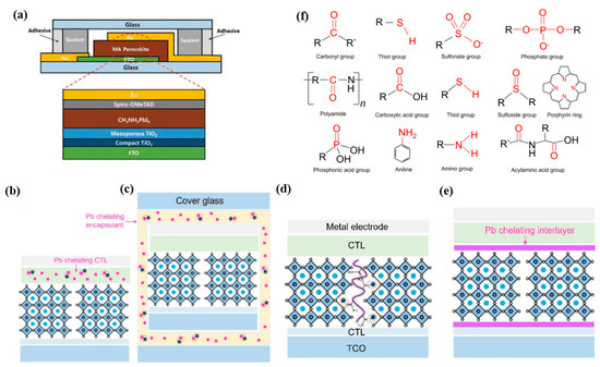
Figure 15.
(a) Simplified schematic images of PVSC device architecture and encapsulation, along with low-resolution images of the actual PVSC device from the top, front, and back [125]. (b) and (c) Encapsulation using Pb chelating charge transport layers (CTLs) and Pb chelating encapsulants. (d,e) Pb complexation is based on additives or interlayer (or surface passivation layer) [109]. (f) Functional groups are commonly used for Pb complexation [109].
Given the high toxicity of Pb and its potential environmental and health risks, preventing Pb leakage from PV devices is of utmost importance. While physical encapsulation can provide a barrier to prevent volatile decomposition products and protect the PVSCs against moisture and UV radiation, chemical encapsulation can prevent potential Pb leakage from PVSCs more efficiently [126]. Therefore, researchers have explored the use of chemical additives that can capture leaked Pb from the perovskite layer under various environmental conditions.
Two strategies have been pursued to achieve Pb capture: modification of internal functional layers or incorporation of an exterior encapsulant with Pb-chelating materials, as shown in Figure 15b,c. To be effective, an encapsulation layer with a high Pb adsorption rate and capacity is essential. In addition, from a commercial standpoint, encapsulation materials that are abundant, low-cost, and easily processable are desirable.
Materials of epoxy, SnO2, butyl rubber, and dyads are commonly used as carrier transport layers to prevent Pb leakage. Chen [127] has integrated cation-exchange resin into carbon electrodes to prevent lead leakage. Xu [128] has effectively prevented Pb leakage by employing Pb-absorbing materials through chemical reactions between phosphonic acid groups and lead ions. Qi [129] found that encapsulating devices with epoxy resin reduces Pb leakage without affecting device performance. These studies confirm the effectiveness of chemical encapsulation in reducing Pb leakage.
3.2.4. Immobilization of the Pb
As depicted in Figure 15d,e, the immobilization of Pb refers to the incorporation of special materials into the perovskite layer or surface, which interact with Pb2+ ions during perovskite degradation. These materials act as additives or interlayer and surface passivation layers, respectively. Compared to device encapsulation, immobilization of Pb is not as effective in preventing Pb leakage from the device. However, materials that immobilize Pb can also improve the crystallinity of the perovskite layer and passivate defects in the perovskite film [109]. Therefore, various materials with strong electron-donating functional groups have been introduced into the perovskite layer, as summarized in Figure 15f. These functional groups include carbonyl, thiol, sulfonate, phosphate groups, etc.
Niu et al. [130] introduced a polymerizable acrylamide (AAm) monomer additive into a perovskite precursor solution, resulting in more than a 50% reduction in lead with an improved PCE of 10%. Bi et al. [131] demonstrated a PVSC modified with 3-mercaptopropyl-tri-ethoxy-silane that exhibited a PCE of 22.18%, compared to 19.87% of the initial device, while the lead leakage concentration was reduced threefold. In 2021, Li et al. [132] suggested a 4-[(trifluoromethyl) sulfonyl] aniline (4TA) material with an aniline group. When the device was immersed in pH 5.6 deionized water for 60 s, the Pb2+ concentration of the modified 4TA device was significantly lower than that of the control device.
4. Conclusions and Perspective
The commercialization of PVSCs has been impeded by several obstacles, among which the issue of toxicity is a major concern. Despite the rapid development of PVSCs, the toxicity of Pb-based PVSCs has not been effectively resolved, which makes it impossible to scale up their manufacture. Consequently, considerable research effort has been devoted to evaluating and resolving the toxicity of Pb-based PVSCs during their production and application.
One of the primary sources of toxicity is the solvents used in the fabrication process. While the hazards from solvents are relatively less than the toxicity of Pb, the upscale production of PVSCs will result in a significant consumption of DMF, which has adverse effects on both the environment and human health. Therefore, a comprehensive life cycle assessment is necessary to fully understand the hazards to the environment and human health for the commercialization of PVSCs. On the other hand, as DMF is the most toxic material in the precursor solvents, which can easily be absorbed through the skin and cause many adverse health effects, significant efforts have been made to replace DMF partly or completely. While the role of DMF is vital in the solvent treatment, it is nearly impossible to replace it completely. Nevertheless, solvent-free fabrication methods are considered promising but are still under research, as some PVSCs made using this method do not exhibit decent PV performance.
Another major source of toxicity is the Pb materials used in high-performance Pb-based PVSCs. The usage and leakage of Pb have dangerous effects on humans and other living creatures due to its property of easily dissolving in water and being hard to remove from the body. To mitigate the toxicity of Pb-based PVSCs, significant efforts have been made in the development of lead-free PVSCs, Pb recycling technologies, device encapsulation, and immobilization of Pb. Although the development of lead-free PVSCs is the earliest, their PCEs are still below 15%, and their stability remains a significant issue that needs to be resolved. Therefore, the assessment and reduction of the toxicity in Pb-based PVSCs are crucial for their commercialization.
Among the various methods to reduce toxicity, device encapsulation is considered the most efficient, using physical or chemical barriers to prevent the Pb leakage. Recycling technologies are essential for sustainable applications with reduced environmental effects. However, the current mainstream recycling method still involves the use of toxic chemicals, necessitating the establishment of an overall environmental impact assessment and the development of eco-friendly Pb recycling processes. In terms of Pb immobilization strategies, even though they are less effective than encapsulation, their additional advantages, such as enhanced crystallinity and passivation of defects, make them promising for further research.
In conclusion, significant progress has been made in the field of green PVSCs, and it is anticipated that research on nontoxic PVSCs will soon have a breakthrough. We look forward to further development of lead-free perovskite materials and PVSCs that meet environmental requirements. We expect continuous improvements in PVSCs to meet the needs of commercial development.
Author Contributions
Conceptualization, H.G. and Y.C.; methodology, Y.C.; formal analysis, Z.Y.; investigation, Z.Y. and H.G.; resources, Y.C.; writing—original draft preparation, Z.Y. and Y.C.; writing—review and editing, H.G. and Y.C.; supervision, Y.C.; project administration, Y.C. All authors have read and agreed to the published version of the manuscript.
Funding
This research received no external funding.
Data Availability Statement
Not applicable.
Conflicts of Interest
The authors declare no conflict of interest.
References
- Sheng, P.; He, Y.; Guo, X. The impact of urbanization on energy consumption and efficiency. Energy Environ. 2017, 28, 673–686. [Google Scholar] [CrossRef]
- Rabbi, M.F.; Popp, J.; Máté, D.; Kovács, S. Energy Security and Energy Transition to Achieve Carbon Neutrality. Energies 2022, 15, 8126. [Google Scholar] [CrossRef]
- Lekesi, L.P.; Koao, L.F.; Motloung, S.V.; Motaung, T.E.; Malevu, T. Developments on Perovskite Solar Cells (PSCs): A Critical Review. Appl. Sci. 2022, 12, 672. [Google Scholar] [CrossRef]
- Nazir, G.; Lee, S.Y.; Lee, J.H.; Rehman, A.; Lee, J.K.; Seok, S.I.; Park, S.J. Stabilization of Perovskite Solar Cells: Recent Developments and Future Perspectives. Adv. Mater. 2022, 34, 2204380. [Google Scholar] [CrossRef]
- Barichello, J.; Di Girolamo, D.; Nonni, E.; Paci, B.; Generosi, A.; Kim, M.; Levtchenko, A.; Cacovich, S.; Di Carlo, A.; Matteocci, F. Semi-Transparent Blade-Coated FAPbBr3 Perovskite Solar Cells: A Scalable Low-Temperature Manufacturing Process under Ambient Condition. Sol. RRL 2023, 7, 2200739. [Google Scholar] [CrossRef]
- Cheng, Y.; Ding, L. Perovskite/Si tandem solar cells: Fundamentals, advances, challenges, and novel applications. SusMat 2021, 1, 324–344. [Google Scholar] [CrossRef]
- Brinkmann, K.; Becker, T.; Zimmermann, F.; Kreusel, C.; Gahlmann, T.; Theisen, M.; Haeger, T.; Olthof, S.; Tückmantel, C.; Günster, M. Perovskite–organic tandem solar cells with indium oxide interconnect. Nature 2022, 604, 280–286. [Google Scholar] [CrossRef]
- Mahmood, K.; Sarwar, S.; Mehran, M.T. Current status of electron transport layers in perovskite solar cells: Materials and properties. RSC Adv. 2017, 7, 17044–17062. [Google Scholar] [CrossRef]
- Zhang, P.; Wu, J.; Zhang, T.; Wang, Y.; Liu, D.; Chen, H.; Ji, L.; Liu, C.; Ahmad, W.; Chen, Z.D. Perovskite solar cells with ZnO electron-transporting materials. Adv. Mater. 2018, 30, 1703737. [Google Scholar] [CrossRef]
- Jiang, Q.; Zhang, X.; You, J. SnO2: A wonderful electron transport layer for perovskite solar cells. Small 2018, 14, 1801154. [Google Scholar] [CrossRef]
- Umeyama, T.; Imahori, H. Isomer effects of fullerene derivatives on organic photovoltaics and perovskite solar cells. Acc. Chem. Res. 2019, 52, 2046–2055. [Google Scholar] [CrossRef] [PubMed]
- Cai, F.; Cai, J.; Yang, L.; Li, W.; Gurney, R.S.; Yi, H.; Iraqi, A.; Liu, D.; Wang, T. Molecular engineering of conjugated polymers for efficient hole transport and defect passivation in perovskite solar cells. Nano Energy 2018, 45, 28–36. [Google Scholar] [CrossRef]
- Kung, P.K.; Li, M.H.; Lin, P.Y.; Chiang, Y.H.; Chan, C.R.; Guo, T.F.; Chen, P. A review of inorganic hole transport materials for perovskite solar cells. Adv. Mater. Interfaces 2018, 5, 1800882. [Google Scholar] [CrossRef]
- Xia, Y.; Dai, S. Review on applications of PEDOTs and PEDOT: PSS in perovskite solar cells. J. Mater. Sci. Mater. Electron. 2021, 32, 12746–12757. [Google Scholar] [CrossRef]
- Malevu, T.; Mwankemwa, B.; Tshabalala, K.; Diale, M.; Ocaya, R. Effect of 6R and 12R lead iodide polytypes on MAPbI 3 perovskite device performance. J. Mater. Sci. Mater. Electron. 2018, 29, 13011–13018. [Google Scholar] [CrossRef]
- Cheng, Y.; Ding, L. Pushing commercialization of perovskite solar cells by improving their intrinsic stability. Energy Environ. Sci. 2021, 14, 3233–3255. [Google Scholar] [CrossRef]
- Li, G.; Su, Z.; Canil, L.; Hughes, D.; Aldamasy, M.H.; Dagar, J.; Trofimov, S.; Wang, L.; Zuo, W.; Jerónimo-Rendon, J.J. Highly efficient pin perovskite solar cells that endure temperature variations. Science 2023, 379, 399–403. [Google Scholar] [CrossRef] [PubMed]
- Wang, K.-L.; Zhou, Y.-H.; Lou, Y.-H.; Wang, Z.-K. Perovskite indoor photovoltaics: Opportunity and challenges. Chem. Sci. 2021, 12, 11936–11954. [Google Scholar] [CrossRef]
- Liu, C.; Dong, H.; Zhang, Z.; Chai, W.; Li, L.; Chen, D.; Zhu, W.; Xi, H.; Zhang, J.; Zhang, C. Promising applications of wide bandgap inorganic perovskites in underwater photovoltaic cells. Sol. Energy 2022, 233, 489–493. [Google Scholar] [CrossRef]
- Roy, A.; Ghosh, A.; Bhandari, S.; Sundaram, S.; Mallick, T.K. Perovskite solar cells for BIPV application: A review. Buildings 2020, 10, 129. [Google Scholar] [CrossRef]
- Tong, J.; Song, Z.; Kim, D.H.; Chen, X.; Chen, C.; Palmstrom, A.F.; Ndione, P.F.; Reese, M.O.; Dunfield, S.P.; Reid, O.G. Carrier lifetimes of > 1 μs in Sn-Pb perovskites enable efficient all-perovskite tandem solar cells. Science 2019, 364, 475–479. [Google Scholar] [CrossRef] [PubMed]
- Laboratory, N.R.E. Best Research-Cell Efficiency Chart. Available online: https://www.nrel.gov/pv/assets/pdfs/best-research-cell-efficiencies.pdf (accessed on 19 April 2023).
- Kim, J.; Jang, J.H.; Choi, E.; Shin, S.J.; Kim, J.-H.; Jeon, G.G.; Lee, M.; Seidel, J.; Kim, J.H.; Yun, J.S. Chlorine incorporation in perovskite solar cells for indoor light applications. Cell Rep. Phys. Sci. 2020, 1, 100273. [Google Scholar] [CrossRef]
- Bing, J.; Caro, L.G.; Talathi, H.P.; Chang, N.L.; Mckenzie, D.R.; Ho-Baillie, A.W. Perovskite solar cells for building integrated photovoltaics—Glazing applications. Joule 2022, 6, 1446–1474. [Google Scholar] [CrossRef]
- Im, J.-H.; Kim, H.-S.; Park, N.-G. Morphology-photovoltaic property correlation in perovskite solar cells: One-step versus two-step deposition of CH3NH3PbI3. Apl. Mater. 2014, 2, 081510. [Google Scholar] [CrossRef]
- Zeng, J.; Bi, L.; Cheng, Y.; Xu, B.; Jen, A.K.-Y. Self-assembled monolayer enabling improved buried interfaces in blade-coated perovskite solar cells for high efficiency and stability. Nano Res. Energy 2022, 1, e9120004. [Google Scholar] [CrossRef]
- Cheng, Y.; Peng, Y.; Jen, A.K.-Y.; Yip, H.-L. Development and challenges of metal halide perovskite solar modules. Solar RRL 2022, 6, 2100545. [Google Scholar] [CrossRef]
- Seo, Y.-H.; Cho, S.-P.; Lee, H.-J.; Kang, Y.-J.; Kwon, S.-N.; Na, S.-I. Temperature-controlled slot-die coating for efficient and stable perovskite solar cells. J. Power Sources 2022, 539, 231621. [Google Scholar] [CrossRef]
- Patidar, R.; Burkitt, D.; Hooper, K.; Richards, D.; Watson, T. Slot-die coating of perovskite solar cells: An overview. Mater. Today Commun. 2020, 22, 100808. [Google Scholar] [CrossRef]
- Chou, L.-H.; Chan, J.M.; Liu, C.-L. Progress in Spray Coated Perovskite Films for Solar Cell Applications. Solar RRL 2022, 6, 2101035. [Google Scholar] [CrossRef]
- Irshad, Z.; Adnan, M.; Lee, J.K. Simple preparation of highly efficient MA x FA1− x PbI3 perovskite films from an aqueous halide-free lead precursor by all dip-coating approach and application in high-performance perovskite solar cells. J. Mater. Sci. 2022, 57, 1936–1946. [Google Scholar] [CrossRef]
- Rico-Yuson, C.A.; Danwittayakul, S.; Kumar, S.; Hornyak, G.L.; Bora, T. Sequential dip-coating of CsPbBr3 perovskite films in ambient conditions and their photovoltaic performance. J. Mater. Sci. 2022, 57, 10285–10298. [Google Scholar] [CrossRef]
- Lohmann, K.B.; Motti, S.G.; Oliver, R.D.; Ramadan, A.J.; Sansom, H.C.; Yuan, Q.; Elmestekawy, K.A.; Patel, J.B.; Ball, J.M.; Herz, L.M. Solvent-free method for defect reduction and improved performance of pin vapor-deposited perovskite solar cells. ACS Energy Lett. 2022, 7, 1903–1911. [Google Scholar] [CrossRef] [PubMed]
- Li, H.; Zhou, J.; Tan, L.; Li, M.; Jiang, C.; Wang, S.; Zhao, X.; Liu, Y.; Zhang, Y.; Ye, Y. Sequential vacuum-evaporated perovskite solar cells with more than 24% efficiency. Sci. Adv. 2022, 8, eabo7422. [Google Scholar] [CrossRef] [PubMed]
- Du, P.; Wang, L.; Li, J.; Luo, J.; Ma, Y.; Tang, J.; Zhai, T. Thermal evaporation for halide perovskite optoelectronics: Fundamentals, progress, and outlook. Adv. Opt. Mater. 2022, 10, 2101770. [Google Scholar] [CrossRef]
- Bae, S.-R.; Heo, D.; Kim, S. Recent progress of perovskite devices fabricated using thermal evaporation method: Perspective and outlook. Mater. Today Adv. 2022, 14, 100232. [Google Scholar] [CrossRef]
- Li, L.; Fang, Y.; Yang, D. Interlayer-Assisted Growth of Si-Based All-Inorganic Perovskite Films via Chemical Vapor Deposition for Sensitive and Stable X-ray Detection. J. Phys. Chem. Lett. 2022, 13, 5441–5450. [Google Scholar] [CrossRef]
- Chen, C.; Chen, J.; Han, H.; Chao, L.; Hu, J.; Niu, T.; Dong, H.; Yang, S.; Xia, Y.; Chen, Y. Perovskite solar cells based on screen-printed thin films. Nature 2022, 612, 266–271. [Google Scholar] [CrossRef]
- Park, N.-G. Green solvent for perovskite solar cell production. Nat. Sustain. 2021, 4, 192–193. [Google Scholar] [CrossRef]
- Vidal, R.; Alberola-Borràs, J.-A.; Habisreutinger, S.N.; Gimeno-Molina, J.-L.; Moore, D.T.; Schloemer, T.H.; Mora-Seró, I.; Berry, J.J.; Luther, J.M. Assessing health and environmental impacts of solvents for producing perovskite solar cells. Nat. Sustain. 2021, 4, 277–285. [Google Scholar] [CrossRef]
- Chang, J.; Wang, G.; Huang, Y.; Luo, X.; Chen, H. New insights into the electronic structures and optical properties in the orthorhombic perovskite MAPbI3: A mixture of Pb and Ge/Sn. New J. Chem. 2017, 41, 11413–11421. [Google Scholar] [CrossRef]
- Wang, F.; Zhou, X.; Liang, X.; Duan, D.; Ge, C.-Y.; Lin, H.; Zhu, Q.; Li, L.; Hu, H. Solvent Engineering of Ionic Liquids for Stable and Efficient Perovskite Solar Cells. Adv. Energy Sustain. Res. 2023, 4, 2200140. [Google Scholar] [CrossRef]
- Li, N.; Niu, X.; Li, L.; Wang, H.; Huang, Z.; Zhang, Y.; Chen, Y.; Zhang, X.; Zhu, C.; Zai, H. Liquid medium annealing for fabricating durable perovskite solar cells with improved reproducibility. Science 2021, 373, 561–567. [Google Scholar] [CrossRef] [PubMed]
- Su, Y.; Xue, J.; Liu, A.; Ma, T.; Gao, L. Unveiling the Effect of Solvents on Crystallization and Morphology of 2D Perovskite in Solvent-Assisted Method. Molecules 2022, 27, 1828. [Google Scholar] [CrossRef] [PubMed]
- Zhang, Q.; Ma, G.; Green, K.A.; Gollinger, K.; Moore, J.; Demeritte, T.; Ray, P.C.; Hill Jr, G.A.; Gu, X.; Morgan, S.E. FAPbI3 Perovskite Films Prepared by Solvent Self-Volatilization for Photovoltaic Applications. ACS Appl. Energy Mater. 2022, 5, 1487–1495. [Google Scholar] [CrossRef]
- Comstock, A.H.; Chou, C.-T.; Wang, Z.; Wang, T.; Song, R.; Sklenar, J.; Amassian, A.; Zhang, W.; Lu, H.; Liu, L. Hybrid magnonics in hybrid perovskite antiferromagnets. Nat. Commun. 2023, 14, 1834. [Google Scholar] [CrossRef]
- Qaid, S.M.; Ghaithan, H.M.; Bawazir, H.S.; Aldwayyan, A.S. Simple approach for crystallizing growth of MAPbI3 perovskite nanorod without thermal annealing for Next-Generation optoelectronic applications. Mater. Chem. Phys. 2023, 298, 127423. [Google Scholar] [CrossRef]
- Zhang, Z.; Liang, J.; Wang, J.; Zheng, Y.; Wu, X.; Tian, C.; Sun, A.; Huang, Y.; Zhou, Z.; Yang, Y. DMSO-Free Solvent Strategy for Stable and Efficient Methylammonium-Free Sn–Pb Alloyed Perovskite Solar Cells. Adv. Energy Mater. 2023, 13, 2300181. [Google Scholar] [CrossRef]
- Song, J.; Yang, Y.; Zhao, Y.; Che, M.; Zhu, L.; Gu, X.; Qiang, Y. Morphology modification of perovskite film by a simple post-treatment process in perovskite solar cell. Mater. Sci. Eng. B 2017, 217, 18–25. [Google Scholar] [CrossRef]
- Cao, X.; Hao, L.; Liu, Z.; Su, G.; He, X.; Zeng, Q.; Wei, J. All green solvent engineering of organic–inorganic hybrid perovskite layer for high-performance solar cells. Chem. Eng. J. 2022, 437, 135458. [Google Scholar] [CrossRef]
- Hamill Jr, J.C.; Schwartz, J.; Loo, Y.-L. Influence of solvent coordination on hybrid organic–inorganic perovskite formation. ACS Energy Lett. 2017, 3, 92–97. [Google Scholar] [CrossRef]
- Jones, E.W.; Holliman, P.J.; Connell, A.; Davies, M.L.; Baker, J.; Hobbs, R.J.; Ghosh, S.; Furnell, L.; Anthony, R.; Pleydell-Pearce, C. A novel dimethylformamide (DMF) free bar-cast method to deposit organolead perovskite thin films with improved stability. Chem. Commun. 2016, 52, 4301–4304. [Google Scholar] [CrossRef] [PubMed]
- Li, M.-J.; Zeng, T. The deleterious effects of N, N-dimethylformamide on liver: A mini-review. Chem.-Biol. Interact. 2019, 298, 129–136. [Google Scholar] [CrossRef] [PubMed]
- Wrbitzky, R. Liver function in workers exposed to N, N-dimethylformamide during the production of synthetic textiles. Int. Arch. Occup. Environ. Health 1999, 72, 19–25. [Google Scholar] [CrossRef]
- Scailteur, V.; Lauwerys, R. Dimethylformamide (DMF) hepatotoxicity. Toxicology 1987, 43, 231–238. [Google Scholar] [CrossRef]
- Lauwerys, R.; Kivits, A.; Lhoir, M.; Rigolet, P.; Houbeau, D.; Buchet, J.-P.; Roels, H. Biological surveillance of workers exposed to dimethylformamide and the influence of skin protection on its percutaneous absorption. Int. Arch. Occup. Environ. Health 1980, 45, 189–203. [Google Scholar] [CrossRef] [PubMed]
- Zheng, X.; Chen, B.; Wu, C.; Priya, S. Room temperature fabrication of CH3NH3PbBr3 by anti-solvent assisted crystallization approach for perovskite solar cells with fast response and small J–V hysteresis. Nano Energy 2015, 17, 269–278. [Google Scholar] [CrossRef]
- Fritz, H.; Reineke, W.; Schmidt, E. Toxicity of chlorobenzene on Pseudomonas sp. strain RHO1, a chlorobenzene-degrading strain. Biodegradation 1991, 2, 165–170. [Google Scholar] [CrossRef] [PubMed]
- Oesch, F.; Jerina, D.M.; Daly, J.W.; Rice, J.M. Induction, activation and inhibition of epoxide hydrase: An anomalous prevention of chlorobenzene-induced hepatotoxicity by an inhibitor of epoxide hydrase. Chem.-Biol. Interact. 1973, 6, 189–202. [Google Scholar] [CrossRef]
- Willhite, C.; Book, S. Toxicology update: Chlorobenzene. J. Appl. Toxicol. 1990, 10, 307–310. [Google Scholar] [CrossRef]
- Donald, J.M.; Hooper, K.; Hopenhayn-Rich, C. Reproductive and developmental toxicity of toluene: A review. Environ. Health Perspect. 1991, 94, 237–244. [Google Scholar]
- Filley, C.M.; Halliday, W.; Kleinschmidt-DeMasters, B. The effects of toluene on the central nervous system. J. Neuropathol. Exp. Neurol. 2004, 63, 1–12. [Google Scholar] [CrossRef] [PubMed]
- Echeverria, D.; Fine, L.; Langolf, G.; Schork, A.; Sampaio, C. Acute neurobehavioural effects of toluene. Occup. Environ. Med. 1989, 46, 483–495. [Google Scholar] [CrossRef] [PubMed]
- Cho, S.; Pandey, P.; Park, J.; Lee, T.-W.; Kang, D.-W. Mixed Solvent Engineering for Morphology Optimization of the Electron Transport Layer in Perovskite Photovoltaics. ACS Appl. Energy Mater. 2021, 5, 387–396. [Google Scholar] [CrossRef]
- Tsai, C.-H.; Lin, C.-M.; Kuei, C.-H. Investigation of the effects of various organic solvents on the PCBM electron transport layer of perovskite solar cells. Coatings 2020, 10, 237. [Google Scholar] [CrossRef]
- Heo, D.Y.; Jang, W.J.; Jeong, M.J.; Noh, J.H.; Kim, S.Y. Optimal Solvents for Interfacial Solution Engineering of Perovskite Solar Cells. Solar RRL 2022, 6, 2200485. [Google Scholar] [CrossRef]
- Bu, T.; Wu, L.; Liu, X.; Yang, X.; Zhou, P.; Yu, X.; Qin, T.; Shi, J.; Wang, S.; Li, S. Synergic interface optimization with green solvent engineering in mixed perovskite solar cells. Adv. Energy Mater. 2017, 7, 1700576. [Google Scholar] [CrossRef]
- Lee, J.; Kim, G.W.; Kim, M.; Park, S.A.; Park, T. Nonaromatic green-solvent-processable, dopant-free, and lead-capturable hole transport polymers in perovskite solar cells with high efficiency. Adv. Energy Mater. 2020, 10, 1902662. [Google Scholar] [CrossRef]
- Ashurst, J.V.; Nappe, T.M. Isopropanol Toxicity. 2018. Available online: https://europepmc.org/article/NBK/nbk493181 (accessed on 19 April 2023).
- Versonnen, B.J.; Arijs, K.; Verslycke, T.; Lema, W.; Janssen, C.R. In vitro and in vivo estrogenicity and toxicity of o-, m-, and p-dichlorobenzene. Environ. Toxicol. Chem. Int. J. 2003, 22, 329–335. [Google Scholar] [CrossRef]
- Feuston, M.; Bodnar, K.; Kerstetter, S.; Grink, C.; Belcak, M.; Singer, E. Reproductive toxicity of 2-methoxyethanol applied dermally to occluded and nonoccluded sites in male rats. Toxicol. Appl. Pharmacol. 1989, 100, 145–161. [Google Scholar] [CrossRef]
- Ono, L.K.; Park, N.-G.; Zhu, K.; Huang, W.; Qi, Y. Perovskite Solar Cells Towards Commercialization. ACS Energy Lett. 2017, 2, 1749–1751. [Google Scholar] [CrossRef]
- Galagan, Y. Perovskite solar cells: Toward industrial-scale methods. J. Phys. Chem. Lett. 2018, 9, 4326–4335. [Google Scholar] [CrossRef] [PubMed]
- Ding, G.; Zheng, Y.; Xiao, X.; Cheng, H.; Zhang, G.; Shi, Y.; Shao, Y. Sustainable development of perovskite solar cells: Keeping a balance between toxicity and efficiency. J. Mater. Chem. A 2022, 10, 8159–8171. [Google Scholar] [CrossRef]
- PubChem Compound Summary for CID 6228, N,N-Dimethylformamide. Available online: https://pubchem.ncbi.nlm.nih.gov/compound/N_N-Dimethylformamide (accessed on 19 April 2023).
- PubChem Compound Summary for CID 679, Dimethyl Sulfoxide. Available online: https://pubchem.ncbi.nlm.nih.gov/compound/Dimethyl-Sulfoxide (accessed on 19 April 2023).
- PubChem Compound Summary for CID 31374, N,N-Dimethylacetamide. Available online: https://pubchem.ncbi.nlm.nih.gov/compound/N_N-Dimethylacetamide (accessed on 19 April 2023).
- PubChem Compound Summary for CID 13387, 1-Methyl-2-pyrrolidinone. Available online: https://pubchem.ncbi.nlm.nih.gov/compound/1-Methyl-2-pyrrolidinone (accessed on 19 April 2023).
- PubChem Compound Summary for CID 86594259, n-hexane DMI. Available online: https://pubchem.ncbi.nlm.nih.gov/compound/n-hexane-DMI (accessed on 19 April 2023).
- PubChem Compound Summary for CID 7302, gamma-Butyrolactone. Available online: https://pubchem.ncbi.nlm.nih.gov/compound/gamma-Butyrolactone (accessed on 19 April 2023).
- PubChem Compound Summary for CID 8028, Tetrahydrofuran. Available online: https://pubchem.ncbi.nlm.nih.gov/compound/Tetrahydrofuran (accessed on 19 April 2023).
- PubChem Compound Summary for CID 81646, 1,3-Dimethyl-3,4,5,6-tetrahydro-2(1H)-pyrimidinone. Available online: https://pubchem.ncbi.nlm.nih.gov/compound/1_3-dimethyl-1_3-diazinan-2-one (accessed on 19 April 2023).
- Gong, J.; Darling, S.B.; You, F. Perovskite photovoltaics: Life-cycle assessment of energy and environmental impacts. Energy Environ. Sci. 2015, 8, 1953–1968. [Google Scholar] [CrossRef]
- Cui, Y.; Wang, S.; Ding, L.; Hao, F. Green–solvent–processable perovskite solar cells. Adv. Energy Sustain. Res. 2021, 2, 2000047. [Google Scholar] [CrossRef]
- Jang, G.; Ma, S.; Kwon, H.-C.; Goh, S.; Ban, H.; Lee, J.; Lee, C.U.; Moon, J. Binary antisolvent bathing enabled highly efficient and uniform large-area perovskite solar cells. Chem. Eng. J. 2021, 423, 130078. [Google Scholar] [CrossRef]
- Li, J.; Hua, X.; Gao, F.; Ren, X.; Zhang, C.; Han, Y.; Li, Y.; Shi, B.; Liu, S.F. Green antisolvent additive engineering to improve the performance of perovskite solar cells. J. Energy Chem. 2022, 66, 1–8. [Google Scholar] [CrossRef]
- Zhang, P.; Gu, N.; Song, L.; Chen, X.; Du, P.; Zha, L.; Chen, W.-H.; Xiong, J. The disappearing additive: Introducing volatile ethyl acetate into a perovskite precursor for fabricating high efficiency stable devices in open air. Nanoscale 2022, 14, 5204–5213. [Google Scholar] [CrossRef]
- Stancu, V.; Tomulescu, A.G.; Leonat, L.N.; Balescu, L.M.; Galca, A.C.; Toma, V.; Besleaga, C.; Derbali, S.; Pintilie, I. Partial Replacement of Dimethylformamide with Less Toxic Solvents in the Fabrication Process of Mixed-Halide Perovskite Films. Coatings 2023, 13, 378. [Google Scholar] [CrossRef]
- Cao, X.; Zhang, G.; Jiang, L.; Cai, Y.; Wang, Y.; He, X.; Zeng, Q.; Chen, J.; Jia, Y.; Wei, J. Achieving environment-friendly production of CsPbBr 3 films for efficient solar cells via precursor engineering. Green Chem. 2021, 23, 2104–2112. [Google Scholar] [CrossRef]
- Cao, X.; Zhang, G.; Cai, Y.; Jiang, L.; Yang, W.; Song, W.; He, X.; Zeng, Q.; Jia, Y.; Wei, J. A sustainable solvent system for processing CsPbBr 3 films for solar cells via an anomalous sequential deposition route. Green Chem. 2021, 23, 470–478. [Google Scholar] [CrossRef]
- Wang, J.; Di Giacomo, F.; Brüls, J.; Gorter, H.; Katsouras, I.; Groen, P.; Janssen, R.A.; Andriessen, R.; Galagan, Y. Highly efficient perovskite solar cells using non-toxic industry compatible solvent system. Solar RRL 2017, 1, 1700091. [Google Scholar] [CrossRef]
- Cheng, J.; Fan, Z.; Dong, J. Research Progress of Green Solvent in CsPbBr3 Perovskite Solar Cells. Nanomaterials 2023, 13, 991. [Google Scholar] [CrossRef] [PubMed]
- Li, X.; Tan, Y.; Lai, H.; Li, S.; Chen, Y.; Li, S.; Xu, P.; Yang, J. All-inorganic CsPbBr3 perovskite solar cells with 10.45% efficiency by evaporation-assisted deposition and setting intermediate energy levels. ACS Appl. Mater. Interfaces 2019, 11, 29746–29752. [Google Scholar] [CrossRef] [PubMed]
- Li, J.; Wang, H.; Chin, X.Y.; Dewi, H.A.; Vergeer, K.; Goh, T.W.; Lim, J.W.M.; Lew, J.H.; Loh, K.P.; Soci, C. Highly efficient thermally co-evaporated perovskite solar cells and mini-modules. Joule 2020, 4, 1035–1053. [Google Scholar] [CrossRef]
- Babayigit, A.; Ethirajan, A.; Muller, M.; Conings, B. Toxicity of organometal halide perovskite solar cells. Nature materials 2016, 15, 247–251. [Google Scholar] [CrossRef] [PubMed]
- Wu, T.; Qin, Z.; Wang, Y.; Wu, Y.; Chen, W.; Zhang, S.; Cai, M.; Dai, S.; Zhang, J.; Liu, J. The main progress of perovskite solar cells in 2020–2021. Nano-Micro Lett. 2021, 13, 152. [Google Scholar] [CrossRef]
- Hailegnaw, B.; Kirmayer, S.; Edri, E.; Hodes, G.; Cahen, D. Rain on methylammonium lead iodide based perovskites: Possible environmental effects of perovskite solar cells. J. Phys. Chem. Lett. 2015, 6, 1543–1547. [Google Scholar] [CrossRef]
- CHEN, S.-b.; Meng, W.; LI, S.-s.; ZHAO, Z.-q.; Wen-di, E. Overview on current criteria for heavy metals and its hint for the revision of soil environmental quality standards in China. J. Integr. Agric. 2018, 17, 765–774. [Google Scholar] [CrossRef]
- Rabinowitz, M.B.; Wetherill, G.W.; Kopple, J.D. Kinetic analysis of lead metabolism in healthy humans. J. Clin. Investig. 1976, 58, 260–270. [Google Scholar] [CrossRef]
- Ellenhorn, M.J.; Barceloux, D.G. Medical Toxicology: Diagnosis and Treatment of Human Poisoning; Elsevier: New York, NY, USA, 1988. [Google Scholar]
- Goodman, L.S.; Gilman, A. The Pharmacological Basis of Therapeutics; The Macmillan: New York, NY, USA, 1955. [Google Scholar]
- World Health Organization. Exposure to Lead: A Major Public Health Concern. 2010. Available online: https://www.who.int/publications/i/item/9789240037632 (accessed on 19 April 2023).
- Cullen, G.; Dines, A.; Kolev, S. Monograph for UKPID: Lead. Natl. Poisons Inf. Serv. 1996. Available online: https://inchem.org/documents/ukpids/ukpids/ukpid25.htm (accessed on 19 April 2023).
- World Health Organization. Environmental Health Criteria 3. Lead. Environ. Health Criteria 3 Lead. 1977. Available online: https://wedocs.unep.org/handle/20.500.11822/29263;jsessionid=9586356DB86BBFCDEF8D50499A1AA675 (accessed on 19 April 2023).
- Fewtrell, L.; Kaufman, R.; Prüss-Üstün, A. Lead: Assessing the Environmental Burden of Diseases at National and Local Levels. 2003. Available online: https://apps.who.int/iris/bitstream/handle/10665/42715/9241546107.pdf (accessed on 19 April 2023).
- de Menorval, M.-A.; Mir, L.M.; Fernández, M.L.; Reigada, R. Effects of dimethyl sulfoxide in cholesterol-containing lipid membranes: A comparative study of experiments in silico and with cells. PLoS ONE 2012, 7, e41733. [Google Scholar] [CrossRef]
- Wang, M.; Wang, W.; Ma, B.; Shen, W.; Liu, L.; Cao, K.; Chen, S.; Huang, W. Lead-free perovskite materials for solar cells. Nano-Micro Lett. 2021, 13, 62. [Google Scholar] [CrossRef] [PubMed]
- Filip, M.R.; Giustino, F. Computational screening of homovalent lead substitution in organic–inorganic halide perovskites. J. Phys. Chem. C 2016, 120, 166–173. [Google Scholar] [CrossRef]
- Kim, G.Y.; Kim, K.; Kim, H.J.; Jung, H.S.; Jeon, I.; Lee, J.W. Sustainable and environmentally viable perovskite solar cells. EcoMat 2023, 5, e12319. [Google Scholar] [CrossRef]
- Sun, Y.-Y.; Shi, J.; Lian, J.; Gao, W.; Agiorgousis, M.L.; Zhang, P.; Zhang, S. Discovering lead-free perovskite solar materials with a split-anion approach. Nanoscale 2016, 8, 6284–6289. [Google Scholar] [CrossRef] [PubMed]
- Jiang, X.; Li, H.; Zhou, Q.; Wei, Q.; Wei, M.; Jiang, L.; Wang, Z.; Peng, Z.; Wang, F.; Zang, Z. One-step synthesis of SnI2·(DMSO) x adducts for high-performance tin perovskite solar cells. J. Am. Chem. Soc. 2021, 143, 10970–10976. [Google Scholar] [CrossRef]
- Giorgi, G.; Fujisawa, J.-I.; Segawa, H.; Yamashita, K. Small photocarrier effective masses featuring ambipolar transport in methylammonium lead iodide perovskite: A density functional analysis. J. Phys. Chem. Lett. 2013, 4, 4213–4216. [Google Scholar] [CrossRef]
- Park, S.Y.; Park, J.-S.; Kim, B.J.; Lee, H.; Walsh, A.; Zhu, K.; Kim, D.H.; Jung, H.S. Sustainable lead management in halide perovskite solar cells. Nat. Sustain. 2020, 3, 1044–1051. [Google Scholar] [CrossRef]
- Park, B.W.; Philippe, B.; Zhang, X.; Rensmo, H.; Boschloo, G.; Johansson, E.M. Bismuth based hybrid perovskites A3Bi2I9 (A: Methylammonium or cesium) for solar cell application. J. Adv. Mater. 2015, 27, 6806–6813. [Google Scholar] [CrossRef]
- Nie, R.; Mehta, A.; Park, B.-w.; Kwon, H.-W.; Im, J.; Seok, S.I. Mixed sulfur and iodide-based lead-free perovskite solar cells. J. Am. Chem. Soc. 2018, 140, 872–875. [Google Scholar] [CrossRef]
- Abd Mutalib, M.; Ahmad Ludin, N.; Nik Ruzalman, N.A.A.; Barrioz, V.; Sepeai, S.; Mat Teridi, M.A.; Su’ait, M.S.; Ibrahim, M.A.; Sopian, K. Progress towards highly stable and lead-free perovskite solar cells. Mater. Renew. Sustain. Energy 2018, 7, 7. [Google Scholar] [CrossRef]
- Wang, H.; Chen, X.; Li, X.; Qu, J.; Xie, H.; Gao, S.; Wang, D.; Yin, H. Recovery of lead and iodine from spent perovskite solar cells in molten salt. Chem. Eng. J. 2022, 447, 137498. [Google Scholar] [CrossRef]
- Poll, C.G.; Nelson, G.W.; Pickup, D.M.; Chadwick, A.V.; Riley, D.J.; Payne, D.J. Electrochemical recycling of lead from hybrid organic–inorganic perovskites using deep eutectic solvents. Green Chem. 2016, 18, 2946–2955. [Google Scholar] [CrossRef]
- Feng, X.; Guo, Q.; Xiu, J.; Ying, Z.; Ng, K.W.; Huang, L.; Wang, S.; Pan, H.; Tang, Z.; He, Z. Close-loop recycling of perovskite solar cells through dissolution-recrystallization of perovskite by butylamine. Cell Rep. Phys. Sci. 2021, 2, 100341. [Google Scholar] [CrossRef]
- Wang, K.; Ye, T.; Huang, X.; Hou, Y.; Yoon, J.; Yang, D.; Hu, X.; Jiang, X.; Wu, C.; Zhou, G. “One-key-reset” recycling of whole perovskite solar cell. Matter 2021, 4, 2522–2541. [Google Scholar] [CrossRef]
- Huang, Y.-Y.; Gollavelli, G.; Chao, Y.-H.; Hsu, C.-S. Rejuvenation of perovskite solar cells. J. Mater. Chem. C 2016, 4, 7595–7600. [Google Scholar] [CrossRef]
- Xu, J.; Hu, Z.; Huang, L.; Huang, X.; Jia, X.; Zhang, J.; Zhang, J.; Zhu, Y. In situ recycle of PbI2 as a step towards sustainable perovskite solar cells. Prog. Photovolt. Res. Appl. 2017, 25, 1022–1033. [Google Scholar] [CrossRef]
- Chhillar, P.; Dhamaniya, B.P.; Dutta, V.; Pathak, S. Recycling of perovskite films: Route toward cost-efficient and environment-friendly perovskite technology. ACS Omega 2019, 4, 11880–11887. [Google Scholar] [CrossRef] [PubMed]
- Lee, Y.I.; Jeon, N.J.; Kim, B.J.; Shim, H.; Yang, T.Y.; Seok, S.I.; Seo, J.; Im, S.G. A low-temperature thin-film encapsulation for enhanced stability of a highly efficient perovskite solar cell. Adv. Energy Mater. 2018, 8, 1701928. [Google Scholar] [CrossRef]
- Kim, N.-K.; Min, Y.H.; Noh, S.; Cho, E.; Jeong, G.; Joo, M.; Ahn, S.-W.; Lee, J.S.; Kim, S.; Ihm, K. Investigation of thermally induced degradation in CH3NH3PbI3 perovskite solar cells using in-situ synchrotron radiation analysis. Sci. Rep. 2017, 7, 4645. [Google Scholar] [CrossRef]
- Su, P.; Liu, Y.; Zhang, J.; Chen, C.; Yang, B.; Zhang, C.; Zhao, X. Pb-based perovskite solar cells and the underlying pollution behind clean energy: Dynamic leaching of toxic substances from discarded perovskite solar cells. J. Phys. Chem. Lett. 2020, 11, 2812–2817. [Google Scholar] [CrossRef]
- Chen, S.; Deng, Y.; Gu, H.; Xu, S.; Wang, S.; Yu, Z.; Blum, V.; Huang, J. Trapping lead in perovskite solar modules with abundant and low-cost cation-exchange resins. Nat. Energy 2020, 5, 1003–1011. [Google Scholar] [CrossRef]
- Li, X.; Zhang, F.; He, H.; Berry, J.J.; Zhu, K.; Xu, T. On-device lead sequestration for perovskite solar cells. Nature 2020, 578, 555–558. [Google Scholar] [CrossRef] [PubMed]
- Jiang, L.; Li, Z.; Wang, R. Long non-coding RNAs in lung cancer: Regulation patterns, biologic function and diagnosis implications. Int. J. Oncol. 2019, 55, 585–596. [Google Scholar] [CrossRef] [PubMed]
- Niu, B.; Wu, H.; Yin, J.; Wang, B.; Wu, G.; Kong, X.; Yan, B.; Yao, J.; Li, C.-Z.; Chen, H. Mitigating the lead leakage of high-performance perovskite solar cells via in situ polymerized networks. ACS Energy Lett. 2021, 6, 3443–3449. [Google Scholar] [CrossRef]
- Bi, H.; Han, G.; Guo, M.; Ding, C.; Zou, H.; Shen, Q.; Hayase, S.; Hou, W. Multistrategy Preparation of Efficient and Stable Environment-Friendly Lead-Based Perovskite Solar Cells. ACS Appl. Mater. 2022, 14, 35513–35521. [Google Scholar] [CrossRef] [PubMed]
- Li, X.; Du, J.; Duan, H.; Wang, H.; Fan, L.; Sun, Y.; Sui, Y.; Yang, J.; Wang, F.; Yang, L. Moisture-preventing MAPbI3 solar cells with high photovoltaic performance via multiple ligand engineering. Nano Res. 2022, 15, 1375–1382. [Google Scholar] [CrossRef]
Disclaimer/Publisher’s Note: The statements, opinions and data contained in all publications are solely those of the individual author(s) and contributor(s) and not of MDPI and/or the editor(s). MDPI and/or the editor(s) disclaim responsibility for any injury to people or property resulting from any ideas, methods, instructions or products referred to in the content. |
© 2023 by the authors. Licensee MDPI, Basel, Switzerland. This article is an open access article distributed under the terms and conditions of the Creative Commons Attribution (CC BY) license (https://creativecommons.org/licenses/by/4.0/).