Abstract
This study focuses on the critical connection area between type IV hydrogen storage vessels and external valves, which is commonly referred to as the BOSS structure. The novel BOSS structures were proposed to further ensure the safety of pressure vessels. In order to identify optimal structure that meet industrial requirements, finite element models were performed to analyze and compare the effectiveness of the proposed models in terms of strength, fatigue, and sealing performance. Some influences were discussed, including the angle of inclination of the stop-rotation platform and the number of sealing grooves in the BOSS structures. The results showed that the fatigue life of the proposed BOSS structures can exceed the design life of 30,000 cycles using austenitic stainless steel S31603. The maximum contact stresses were higher than the operating pressure of 58 MPa. Additionally, The BOSS structure model designed with a stop-rotation platform featuring a 65° tilt angle and two sealing grooves had the lowest mean square deviation of contact stress, which was 13.47 MPa, indicating reliable sealing performance.
1. Introduction
Hydrogen is gaining attention as a promising renewable energy source, due to its clean and abundant properties [1,2,3]. To promote the large-scale application of hydrogen fuel cell vehicles, many countries have launched research initiatives aimed at optimizing the design of type IV hydrogen storage vessels [4,5,6].
As shown in Figure 1, type IV hydrogen storage vessel consists of a polymer inner liner that provides a protective barrier to prevent hydrogen leakage, which is then wrapped by an outer layer of fiber reinforced composites. The composite layer is typically composed of carbon or a hybrid mix of carbon and glass fibers [7], which can withstand high mechanical stresses resulting from internal pressures. Notably, the polymer inner liner features a threaded metallic BOSS that provides a reliable attachment point for valves [8]. The BOSS structure therefore plays a key role in connecting the plastic inner liner and carbon fiber layer to the external metallic valves at the head of the vessels. However, due to the variable thermal expansion properties of these materials under high pressure, hydrogen leakage [9] can easily occur at the connection area during cyclic hydrogen charging and discharging, causing damage to the equipment and endangering people’s lives [10]. According to the H2 Hydrogen Tools database, a serious incident occurred in 2017 during the refueling of a fuel cell-powered lift truck, where a significant hydrogen leak occurred. The leak was caused by the inadequate sealing of the BOSS structure, which resulted in the failure of the O-ring. As a result, the entire contents of the hydrogen storage vessel were released in about 10 min, which caused a hazardous situation. Fuyuan Yang et al. [11] concluded that the failures in the connection area were responsible for 35.78% of hydrogen accidents, indicating the importance of studying the BOSS structure and its reliability [12].

Figure 1.
Type IV hydrogen storage vessel.
Previous studies have optimized BOSS structures to help improve the design of other components of hydrogen storage vessels, such as the dome [13,14] and composite layer winding [15,16,17]. Gunyoung Park et al. [14] focused on optimizing the dome and used response surface methods to optimize the height, width, and angle of the BOSS structure’s contact area with the dome. Akira Yamashita et al. [17] optimized the BOSS structure to reduce the usage of composite layers by increasing the flange diameter and decreasing the opening-end diameter.
Finite element (FE) models are widely used to analyze structural integrity and mechanical performance of type IV hydrogen storage vessel [18,19]. Pranjali and Swati [20] established key parameters through simulation that accurately predict the burst pressure and weight of high-pressure hydrogen storage vessels. Zhang et al. [21] investigated a novel multistage pressure-reducing valve at the head of type IV hydrogen storage vessels, which are particularly susceptible to structural damage and fatigue failure. The results showed that the independently designed metal valve was capable of safely and effectively reducing pressure even under challenging conditions.
Gunyoung Park et al. [14] conducted an optimal design of aluminum BOSS that met the structural safety verification with maximum von Mises stresses less than the yield strength and tensile strength under test pressure and burst pressure. Wu et al. [22] developed a fatigue life prediction method and analyzed the factors affecting the fatigue life of vessels by simulation. The results showed that increasing the thickness of the metal liner and composite layers can increase fatigue life of the vessels. Zhou et al. [23,24] examined the sealing performance of different combination sealing structures in high-pressure vessels, where the contact stress and Mises stress of the combination sealing structures were analyzed and discussed. The results showed that the designed sealing structure can meet the required sealing standards. Research primarily focused on the performance of hydrogen storage vessels [15,16], but the comprehensive failure analysis of the BOSS structure is often overlooked.
In this paper, we proposed novel BOSS structures with sealing grooves, stop-rotation platforms, and stop-rotation holes. FE analysis was performed to determine the optimal BOSS structure. The design parameters and BOSS structures are studied in Section 2. The finite element models of the varying BOSS structures are established in Section 3. Section 4 analyzes and compares the properties of the BOSS structures, including strength, fatigue, and sealing performance. Some conclusions are given in the last section. This work addresses the poor connectivity between the polymer inner liner, the BOSS and the composite layer under high pressure, with significant implications for the industrial application of type IV hydrogen storage vessels.
2. Novel BOSS Structures
2.1. Design Parameters
This study focuses on the design of BOSS structure in type IV hydrogen storage vessels, which are specifically suited for large-capacity hydrogen storage in road transportation. The vessels are designed to operate at an operating pressure of 58 MPa within a temperature range of −40 to 60 °C for a service life of 15 to 30 years.
To prevent hydrogen embrittlement, the BOSS structure may be manufactured from either austenitic stainless steel S31603 or aluminum alloy 6061-T6, as recommended in the ISO 11119 [25] and ISO 11114 [26]. The mechanical properties of these two materials are listed in Table 1.

Table 1.
Mechanical properties of austenitic stainless steel S31603 and aluminum alloy 6061-T6.
The BOSS structure should be made from bar or forgings of either aluminum alloy 6061-T6 or austenitic stainless steel S31603 to meet the relevant standards and ensure their suitability for use in the BOSS structure. Specifically, extruded bars for the aluminum alloy should conform to ISO 6362 [27], while forgings should conform to ASTM B247 [28]. As for the austenitic stainless steel, bars should conform to ASTM A479 [29], while forgings should conform to ASTM A965 [30].
2.2. Structure Design
The body of the BOSS structure was designed to match common hydrogen storage vessels sizes and external valves dimensions, and the main structural dimensions are listed in Table 2. The inner threads of BOSS structure can be tightly connected to the external valves, and the outer threads can be used to help secure the hydrogen storage vessels in place.

Table 2.
Main structural dimensions for BOSS structure.
In terms of internal design, the novel BOSS structure features sealing grooves, stop-rotation platforms, and stop-rotation holes to achieve a tight connection between the plastic inner liner, BOSS, and carbon fiber layer. The assembly diagram at the head of the hydrogen storage vessel and the BOSS structure are shown in Figure 2. Circumferential sealing grooves are located on the axial inner surface and lower edge of the BOSS structure, with O-ring seals in the sealing grooves to facilitate a press-fit connection and sealing function with the plastic inner liner. The irregularly shaped stop-rotation platforms are added to the axial outer surface to prevent the hydrogen storage vessel from co-rotating during the winding of the carbon fiber layer, which could cause detachment between the BOSS structure and the carbon fiber layer. The stop-rotation holes are located on the lower edge of the BOSS structure to prevent relative rotation between the BOSS structure and the plastic inner line.
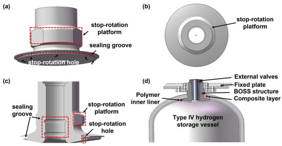
Figure 2.
The assembly diagram at the head of the hydrogen storage vessel and the BOSS structure. (a) Front view of the BOSS structure, (b) top view of the BOSS structure, (c) internal view of the BOSS structure, (d) assembly diagram at the head of the hydrogen storage vessel.
As shown in Figure 3, four BOSS structure models were created, the angle of inclination of the stop-rotation platform, and the number of circumferential sealing grooves on the BOSS structure were also considered to achieve an optimum design. Two materials—aluminum alloy 6061-T6 and austenitic stainless steel S31603—were evaluated for each model. Due to the height limitations of the contact surface between the plastic liner and the BOSS structure, the number of circumferential sealing grooves on the axial inner surface was set at 2 or 3 to ensure better sealing. The angle between the stop-rotation platform and the axial outer surface was controlled between 90°–155° to avoid an excessive angle that would reduce the depth of the external threads on the BOSS structure, further affecting the overall stability and reliability.
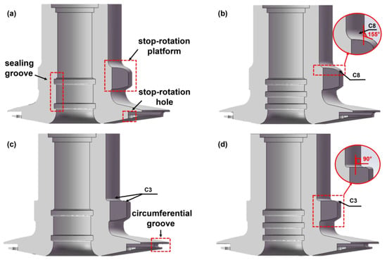
Figure 3.
Four BOSS structure models for type IV hydrogen storage vessels: (a) Model A, (b) Model B, (c) Model C, (d) Model D.
Among the different designs, Model A (Figure 3a) features two circumferential sealing grooves on the axial inner surface of the BOSS structure and an angled top surface of the stop-rotation platform at 65° with an 8 mm chamfer. Model B (Figure 3b) has three circumferential sealing grooves on the axial inner surface of the BOSS structure, and the same angled top surface as Model A. Model C (Figure 3c) has two circumferential sealing grooves, the same as Model A, but with a perpendicular top surface of the stop-rotation platform and a 3 mm chamfer. Similarly, Model D (Figure 3d) has three circumferential sealing grooves, the same as Model B, and the same vertical top surface as Model C. Table 3 shows the variation of key parameters for different BOSS structures.

Table 3.
The variation of key parameters for four different BOSS structures.
3. Finite Element Analysis
3.1. Finite Element Modeling
Finite element analyses of pressure vessels with four BOSS models were performed using ABAQUS software. All models were simulated with consistent material properties, uniform mesh settings, and identical loads, boundary conditions, and contact conditions. Taking Model A as an example, the settings are elaborated upon below.
With the aim of accounting for model symmetry, a 2D axisymmetric model of a quarter hydrogen storage vessel with the BOSS structure was developed (as shown in Figure 4). The model consisted of three parts: the carbon fiber layer, the BOSS structure, and the plastic inner liner. Notably, the effect of internal and external threads in the BOSS structure was ignored in the model, while the default carbon fiber layer was assumed to meet the working strength requirements for type IV hydrogen storage vessels. The model was meshed using CAX4 elements with size of 1 mm, as shown in Figure 5.
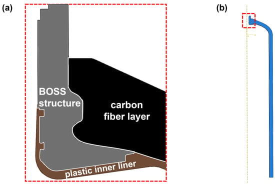
Figure 4.
Finite element model, (a) local model, (b) overall model.
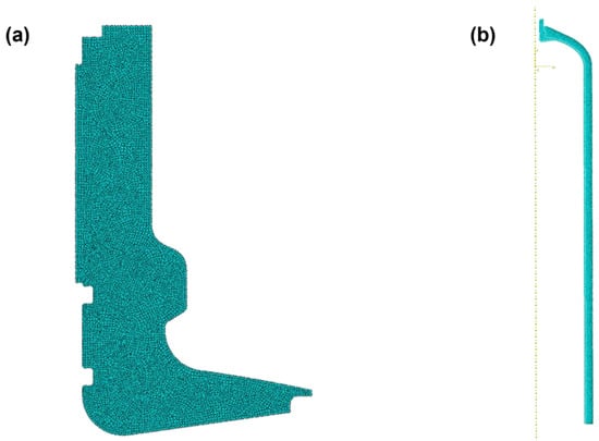
Figure 5.
Model mesh, (a) local mesh, (b) overall mesh.
3.2. Material Properties
As previously stated, the finite element model was composed of the carbon fiber layer, the BOSS structure, and the plastic inner liner. The material parameters for each part are listed in Table 4.

Table 4.
Material parameters for each part of the finite element model.
3.3. Loads, Boundary and Contact Conditions
Figure 6 illustrates the load and boundary condition settings in the finite element analysis. Symmetrical constraints were applied to the cylinder’s 1/2 cross section of the hydrogen storage vessel in the model, while circumferential constraints were placed on the axial outer wall face of the BOSS structure. In terms of load settings, an internal pressure of 58 MPa applied to the inner wall surface of the plastic inner liner in the model and an equilibrium pressure of 28.5 MPa applied to the axial end surface of the BOSS structure in the model.

Figure 6.
Load and boundary condition settings of the model.
The penalty contact algorithm was chosen for its efficient convergence and handling of over-constrained problems, while the Coulomb friction model was used to define friction between the contacting surfaces. We established three contact pairs, as shown in Figure 7, including the BOSS structure-plastic inner liner contact pair, the carbon fiber layer-plastic inner liner contact pair, and the BOSS structure-carbon fiber layer contact pair. Specifically, the carbon fiber layer was chosen as the dominant surface in the carbon fiber layer contact pairs, while the BOSS structure was selected as the dominant surface in the BOSS structure-plastic inner liner contact pair. The coefficient friction between the contact pairs was given as 0.2.
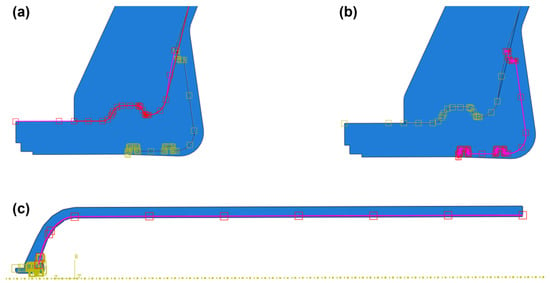
Figure 7.
Contact pairs, (a) BOSS structure-carbon fiber layer, (b) BOSS structure-plastic inner liner, (c) carbon fiber layer-plastic inner liner.
3.4. Finite Element Model Verification
The cylinder of the hydrogen storage vessel model has a diameter of 776 mm, a thickness of 43 mm, and a load of 58 MPa, which makes it a thin-walled container. According to the thin-film theory, the axial and circumferential stresses can be calculated by Equations (1) and (2), respectively.
where is axial stress, is circumferential stress, p is internal pressure, D is the diameter of the cylinder, and is the thickness of the cylinder.
The theoretical solutions for the thin-film stress along the axial and circumferential directions are 261.67 MPa and 523.35 MPa, respectively.
The finite element analysis was also used to calculate the thin-film stress of the model. Figure 8 shows the pathway diagram for the cylinder of the type IV hydrogen storage vessel. The thin-film stress extracted from path N0 was found to be 243 MPa and 523.56 MPa along the axial and circumferential directions, respectively. The values obtained from the finite element method and the analytical solution are almost identical. The validity of the finite element model solutions was therefore verified.

Figure 8.
Pathway diagram for the cylinder of the type IV hydrogen storage vessel.
4. Results and Discussions
It is widely acknowledged that the failure modes of BOSS structures mainly involve stress failure, fatigue failure, and leakage failure. In this section, based on the actual working conditions required in type IV hydrogen storage vessels, strength verification, fatigue failure analysis, and seal failure analysis of the BOSS structures were carried out on two materials: austenitic stainless steel S31603 and aluminum alloy 6061-T6.
4.1. Strength Verification
The strength of the four BOSS structure models for the two aforementioned material was analyzed using the stress classification method based on elastic stress analysis, and the equivalent stress (Mises stress) was considered as the elastic nominal stress. Figure 9 shows the stress clouds diagram for the variable BOSS structures under design pressure conditions. The maximum Mises stresses for each model are listed in Table 5.
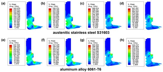
Figure 9.
Stress cloud diagram of BOSS structures: (a) Model A, (b) Model B, (c) Model C, (d) Model D, (e) Model A, (f) Model B, (g) Model C, (h) Model D.

Table 5.
The maximum Mises stresses of four BOSS structure models.
Among the models, Model C reached a maximum Mises stress value of 368.91 MPa with S31603 material and 325.53 MPa with 6061-T6 material. In comparison, Model A, with S31603 material, had the lowest value of 265.98 MPa, and Model B, with 6061-T6 material, had the lowest value of 217.13 MPa. The maximum Mises stress values of Model C and Model D, which were over 100 MPa higher than those of Model A and Model B, suggest that the Mises stress increases rapidly as the angle between the axis and the top surface of the stop-rotation platform increases. However, the groove in the BOSS structure has little effect on the Mises stress. Moreover, the models using 6061-T6 material showed lower maximum Mises stress values than those using S31603 material, indicating better strength performance.
To further evaluate the strength of the models, potential danger areas were identified under operating conditions. Total stresses along these areas were linearized and decomposed into membrane and bending stress components. Static strength evaluations were then conducted on the BOSS structures based on the ASME Boiler and Pressure Vessel Code (BPVC) [31]. Taking Model A as an example, three potentially dangerous paths (N1, N2, and N3) were chosen for the static strength evaluations. These paths ran along the wall thickness of the structure, as shown in Figure 10, with N1 and N2 located at the chamfered edge of the stop-rotation platform and N3 located at the maximum chamfer of the BOSS structure.
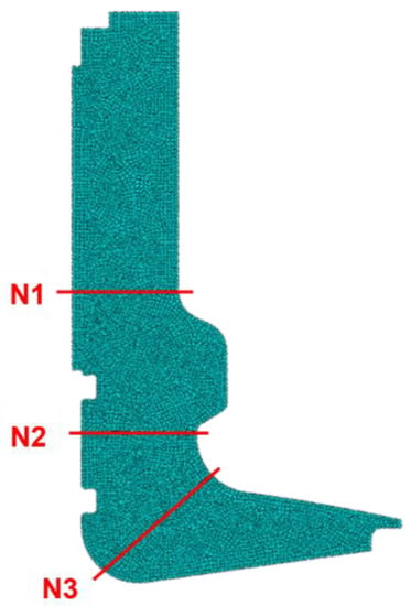
Figure 10.
Pathway diagram of the BOSS structure.
The strength verification results of the different BOSS structure models are presented in Table 6. The allowable stress values () for austenitic stainless steel S31603 and aluminum alloy 6061-T6 were 113 MPa and 103 MPa, respectively. According to Table 6, the maximum equivalent stress in Model A and Model B occurred along the N2 path, with values of 148.26 MPa and 149.25 MPa, respectively. The maximum stress values for models C and D along the N2 path were slightly lower than those for models A and B, with values of 93.59 MPa and 94.42 MPa, respectively. The maximum equivalent stress for models C and D was observed along the N1 path, with values of 113.89 MPa and 113.65 MPa, respectively. The difference in path locations may be attributed to the change in angle between the top surface of the stop-rotation platform and the axis. The equivalent stresses for Model A and Model B using S31603 austenitic stainless steel along the N1 path were 38.18 MPa, 40.50 MPa, 35.90 MPa, and 37.63 MPa. For Model C and Model D, the equivalent stresses were 91.31 MPa, 113.89 MPa, 91.28 MPa, and 113.65 MPa, respectively, showing that the stop-rotation platform with a right-angle design greatly increased the equivalent stress. Notably, the minimum equivalent stress under membrane stress was consistently observed along the N3 path for all models. In addition, the equivalent stress of the models using 6061-T6 material was almost lower than that of the models using S31603 material. Nonetheless, all BOSS models, regardless of the material used, had equivalent stresses less than 1.5 times their allowable stresses and passed the strength verification.

Table 6.
Path stress assessment of four BOSS structure models (stress units: MPa).
4.2. Fatigue Failure Analysis
The design life of the type IV hydrogen storage vessel is a crucial factor to consider when evaluating the fatigue performance of the four different BOSS structure models using two metal materials. This is estimated to be between 30 years, with an expected fatigue cycle life of 30,000 cycles.
Based on the fatigue design curve in ASME-VIII standard, the allowable equivalent stress amplitude of the austenitic stainless steel S31603 material was determined to be 406 MPa, and the allowable equivalent stress amplitude of the aluminum alloy 6061-T6 material was determined to be 68 MPa. The maximum equivalent alternating stress of the BOSS structure was obtained by taking the equivalent stress under the design condition, and the equivalent alternating stress amplitude of the BOSS structure in each design was obtained according to Table 5. The fatigue verification analysis results of the BOSS structures are listed in Table 7.

Table 7.
Fatigue verification analysis of BOSS structures.
The alternating stress amplitudes for Models C and D were higher than those for Models A and B, similarly to the strength verification, showing that the stop-rotation platform with a right-angle design has a negative effect on the BOSS structure. The four BOSS structures using aluminum alloy 6061-T6 had equivalent alternating stress amplitudes of 108.91 MPa, 108.72 MPa, 163.00 MPa, and 162.60 MPa. These values far exceeded the maximum allowable stress amplitude of 68 MPa, indicating that 30,000 fatigue cycles had not been achieved. However, the models with S31603 material demonstrated superior anti-fatigue performance and met the fatigue requirements of the BOSS structure in type IV hydrogen storage vessels. Thus, it is strongly recommended that austenitic stainless steel S31603 be used as the material for the BOSS structure, as it offers adequate fatigue performance to meet the design requirements.
4.3. Seal Failure Analysis
Expanding on the previous section, which recommended the use of austenitic stainless steel S31603 for BOSS structure design, this section exclusively focuses on analyzing the sealing failure of BOSS structures utilizing this material.
The hydrogen leakage mechanism reveals that the interface between the BOSS structure and the plastic inner liner constitutes a heterogeneous contact interface. Due to their small mass, high-pressure hydrogen molecules are susceptible to leaking through the contact surface between the BOSS structure and the plastic inner liner, as evidenced by Juan Pedro Berro Ramirez et al. [32]. To prevent the leakage of high-pressure hydrogen molecules through the interface, it is essential to ensure that the contact stress on the interface meets the sealing failure requirements, which means that the contact stress must exceed the sealing medium pressure. Therefore, taking Model A as an example, the contact interface between the BOSS structure and the plastic inner liner was considered as the hydrogen leakage path, and the contact node set on the contact surface of the BOSS structure was established, which is shown in Figure 11.
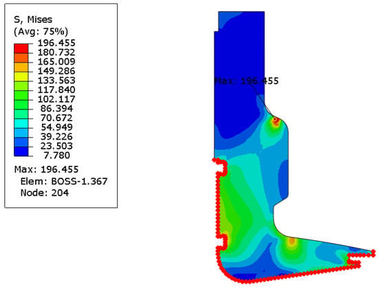
Figure 11.
The contact node set of leakage path.
The contact stress at the contact node set of the BOSS structure was calculated through finite element analysis. The resulting contact stress curve is shown in Figure 12, where the red dashed line denotes the reference line of the 58 MPa sealing medium pressure (PRECESS), and the dark blue solid line represents the contact stress (CPRESS) curve of the BOSS structure contact node set.
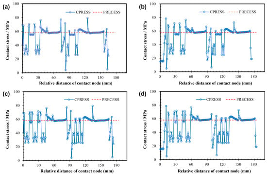
Figure 12.
Contact stress curve of BOSS structure. (a) Model A, (b) Model B, (c) Model C, (d) Model D.
The maximum contact stress of all models was close to 80 MPa, which exceeded the sealing medium pressure of 58 MPa, satisfying the sealing performance requirements. Notably, the maximum contact stress point of Model A and Model C was around the node relative distance of 130 mm, while that of Model B and Model D was around the node relative distance of 10 mm, which may have been related to the variation in the number of sealing grooves. The seal performance analysis results of BOSS structures are listed in Table 8. Model A demonstrated the optimum sealing performance, as evidenced by its minimum mean square deviation of contact stress of 13.47 MPa.

Table 8.
Seal performance analysis of BOSS structures (unit: MPa).
5. Conclusions
Novel BOSS structures with sealing grooves, stop-rotation platforms, and stop-rotation holes were proposed, which could meet the industrial requirements for strength, fatigue, and sealing performance, enabling a tight connection between the polymer inner liner, the BOSS and the composite layer under high pressure. This is of great significance for the actual production of type IV hydrogen storage vessels. Four different BOSS structures of austenitic stainless steel S31603 and aluminum alloy 6061-T6 were simulated and analyzed using the finite element method. Furthermore, the performance test experiments of BOSS structure will be further studied in the future. The key findings are summarized below:
- (1)
- The S31603 and 6061-T6 BOSS models had equivalent stress values less than 1.5 times their allowable stress values of 113 MPa and 103 MPa, respectively, meeting the strength requirements.
- (2)
- Models using S31603 material can achieve 30,000 fatigue cycles, and its maximum contact stresses on their contact surfaces were higher than the reference seal medium pressure of 58 MPa, surpassing the performance of those using the 6061-T6 material. Therefore, S31603 material is recommended for use in the BOSS structure.
- (3)
- After passing the strength and fatigue verification, the model using S31603 material, which was designed with a stop-rotation platform featuring a 65° tilt angle and two sealing grooves, had the lowest mean square deviation of contact stress of 13.47 MPa, indicating optimum sealing performance.
- (4)
- The vertical angle between the stop-rotation platform and the axial outer surface had a negative effect on the BOSS structure, greatly increasing the equivalent stress and the equivalent alternating stress amplitude, while the number of grooves had little effect on the BOSS structure.
Author Contributions
Conceptualization, J.Z. and Y.L. (Yan Li); methodology, J.Z. and Y.L. (Yuebing Li); software, J.Z. and Y.L. (Yan Li); validation, J.Z. and Y.L. (Yan Li); resources, W.C.; writing—original draft preparation, J.Z. and Y.L. (Yan Li); writing—review and editing, J.Z. and Y.L. (Yuebing Li); supervision, Y.L. (Yuebing Li) and Z.G.; project administration, Y.L. (Yuebing Li) and Z.G. All authors have read and agreed to the published version of the manuscript.
Funding
This research was funded by National Key R&D Program of China, grant number 2020YFB150610.
Conflicts of Interest
The authors declare no conflict of interest.
References
- Barthelemy, H.; Weber, M.; Barbier, F. Hydrogen storage: Recent improvements and industrial perspectives. Int. J. Hydrogen Energy 2017, 42, 7254–7262. [Google Scholar] [CrossRef]
- Amirante, R.; Cassone, E.; Distaso, E.; Tamburrano, P. Overview on recent developments in energy storage: Mechanical, electrochemical and hydrogen technologies. Energy Convers. Manag. 2017, 132, 372–387. [Google Scholar] [CrossRef]
- Ren, J.; Toniolo, S. Hydrogen for better sustainability. Int. J. Hydrogen Energy 2020, 45, 34293. [Google Scholar] [CrossRef]
- Itaoka, K.; Saito, A.; Sasaki, K. Public perception on hydrogen infrastructure in Japan: Influence of rollout of commercial fuel cell vehicles. Int. J. Hydrogen Energy 2017, 42, 7290–7296. [Google Scholar] [CrossRef]
- San Marchi, C.; Hecht, E.S.; Ekoto, I.W.; Groth, K.M.; LaFleur, C.; Somerday, B.P.; Mukundan, R.; Rockward, T.; Keller, J.; James, C.W. Overview of the DOE hydrogen safety, codes and standards program, part 3: Advances in research and development to enhance the scientific basis for hydrogen regulations, codes and standards. Int. J. Hydrogen Energy 2017, 42, 7263–7274. [Google Scholar] [CrossRef]
- Ren, X.; Dong, L.; Xu, D.; Hu, B. Challenges towards hydrogen economy in China. Int. J. Hydrogen Energy 2020, 45, 34326–34345. [Google Scholar] [CrossRef]
- Azeem, M.; Ya, H.H.; Alam, M.A.; Kumar, M.; Stabla, P.; Smolnicki, M.; Gemi, L.; Khan, R.; Ahmed, T.; Ma, Q.; et al. Application of Filament Winding Technology in Composite Pressure Vessels and Challenges: A Review. J. Energy Storage 2022, 49, 103468. [Google Scholar] [CrossRef]
- Zhou, W.; Wang, J.; Pan, Z.-b.; Liu, J.; Ma, L.-h.; Zhou, J.-y.; Su, Y.-f. Review on optimization design, failure analysis and non-destructive testing of composite hydrogen storage vessel. Int. J. Hydrogen Energy 2022, 47, 38862–38883. [Google Scholar] [CrossRef]
- Okonkwo, P.C.; Barhoumi, E.M.; Ben Belgacem, I.; Mansir, I.B.; Aliyu, M.; Emori, W.; Uzoma, P.C.; Beitelmal, W.H.; Akyüz, E.; Radwan, A.B.; et al. A focused review of the hydrogen storage tank embrittlement mechanism process. Int. J. Hydrogen Energy 2023, 48, 12935–12948. [Google Scholar] [CrossRef]
- Li, H.; Cao, X.; Liu, Y.; Shao, Y.; Nan, Z.; Teng, L.; Peng, W.; Bian, J. Safety of hydrogen storage and transportation: An overview on mechanisms, techniques, and challenges. Energy Rep. 2022, 8, 6258–6269. [Google Scholar] [CrossRef]
- Yang, F.; Wang, T.; Deng, X.; Dang, J.; Huang, Z.; Hu, S.; Li, Y.; Ouyang, M. Review on hydrogen safety issues: Incident statistics, hydrogen diffusion, and detonation process. Int. J. Hydrogen Energy 2021, 46, 31467–31488. [Google Scholar] [CrossRef]
- West, M.; Al-Douri, A.; Hartmann, K.; Buttner, W.; Groth, K.M. Critical review and analysis of hydrogen safety data collection tools. Int. J. Hydrogen Energy 2022, 47, 17845–17858. [Google Scholar] [CrossRef]
- Coskun, T.; Sahin, O.S. Effects of geodesic dome trajectories on the specific strength of composite overwrapped pressure vessels: FE modelling. Int. J. Hydrogen Energy 2023, 48, 13669–13681. [Google Scholar] [CrossRef]
- Park, G.; Jang, H.; Kim, C. Design of composite layer and liner for structure safety of hydrogen pressure vessel (type 4). J. Mech. Sci. Technol. 2021, 35, 3507–3517. [Google Scholar] [CrossRef]
- Roh, H.S.; Hua, T.Q.; Ahluwalia, R.K. Optimization of carbon fiber usage in Type 4 hydrogen storage tanks for fuel cell automobiles. Int. J. Hydrog. Energy 2013, 38, 12795–12802. [Google Scholar] [CrossRef]
- Leh, D.; Magneville, B.; Saffré, P.; Francescato, P.; Arrieux, R.; Villalonga, S. Optimisation of 700 bar type IV hydrogen pressure vessel considering composite damage and dome multi-sequencing. Int. J. Hydrogen Energy 2015, 40, 13215–13230. [Google Scholar] [CrossRef]
- Yamashita, A.; Kondo, M.; Goto, S.; Ogami, N. Development of High-Pressure Hydrogen Storage System for the Toyota “Mirai”; SAE International: Warrendale, PA, USA, 2015. [Google Scholar]
- Yin, Z.; Su, T.; He, M. Gas Packaging Container Based on ANSYS Finite Element Analysis and Structural Optimization Design. J. Phys. Conf. Ser. 2019, 1187, 032089. [Google Scholar] [CrossRef]
- Nimdum, P.; Patamaprohm, B.; Renard, J.; Villalonga, S. Experimental method and numerical simulation demonstrate non-linear axial behaviour in composite filament wound pressure vessel due to thermal expansion effect. Int. J. Hydrogen Energy 2015, 40, 13231–13241. [Google Scholar] [CrossRef]
- Sharma, P.; Neogi, S. Performance-based design and manufacturing of filament wound Type-4 cylinders for compressed gas storage. Compos. Struct. 2023, 309, 116710. [Google Scholar] [CrossRef]
- Zhang, Y.; Liu, B.; She, X.; Luo, Y.; Sun, Q.; Teng, L. Numerical study on the behavior and design of a novel multistage hydrogen pressure-reducing valve. Int. J. Hydrogen Energy 2022, 47, 14646–14657. [Google Scholar] [CrossRef]
- Wu, E.; Zhao, Y.; Zhao, B.; Xu, W. Fatigue life prediction and verification of high-pressure hydrogen storage vessel. Int. J. Hydrogen Energy 2021, 46, 30412–30422. [Google Scholar] [CrossRef]
- Zhou, C.; Chen, G.; Xiao, S.; Hua, Z.; Gu, C. Study on fretting behavior of rubber O-ring seal in high-pressure gaseous hydrogen. Int. J. Hydrogen Energy 2019, 44, 22569–22575. [Google Scholar] [CrossRef]
- Zhou, C.; Zheng, J.; Gu, C.; Zhao, Y.; Liu, P. Sealing performance analysis of rubber O-ring in high-pressure gaseous hydrogen based on finite element method. Int. J. Hydrogen Energy 2017, 42, 11996–12004. [Google Scholar] [CrossRef]
- ISO-11119; Gas Cylinders of Composite Construction Specification and Test Methods—Part 2: Fully Wrapped Fibre Reinforced Composite Gas Cylinders with Load-sharing Metal Liners. ISO: London, UK, 2002.
- ISO-11114; Gas Cylinders—Compatibility of Cylinder and Valve Materials with Gas Contents—Part 3: Autogenous Ignition Test for Non-Metallic Materials in Oxygen Atmosphere. ISO: London, UK, 2010.
- ISO-6362; Wrought Aluminium and Aluminium Alloys—Extruded Rods/Bars, Tubes and Profiles—Part 1: Technical Conditions for Inspection and Delivery. ISO: London, UK, 2012.
- ASTM-B247; Standard Specification for Aluminum and Aluminum-Alloy Die Forgings, Hand Forgings, and Rolled Ring Forgings. U.S. Department Of Defense: Washington, DC, USA, 2009.
- ASTM-A479; Standard Specification for Stainless Steel Bars and Shapes for Use in Boilers and Other Pressure Vessels. U.S. Department Of Defense: Washington, DC, USA, 2019.
- ASTM-A965; Standard Specification for Steel Forgings, Austenitic, for Pressure and High Temperature Parts. U.S. Department Of Defense: Washington, DC, USA, 2017.
- ASME BPVC.VIII.3-2015; ASME Boiler and Pressure Vessel Code. ASME: New York, NY, USA, 2010.
- Ramirez, J.P.B.; Halm, D.; Grandidier, J.-C.; Villalonga, S.; Nony, F. 700 bar type IV high pressure hydrogen storage vessel burst—Simulation and experimental validation. Int. J. Hydrogen Energy 2015, 40, 13183–13192. [Google Scholar] [CrossRef]
Disclaimer/Publisher’s Note: The statements, opinions and data contained in all publications are solely those of the individual author(s) and contributor(s) and not of MDPI and/or the editor(s). MDPI and/or the editor(s) disclaim responsibility for any injury to people or property resulting from any ideas, methods, instructions or products referred to in the content. |
© 2023 by the authors. Licensee MDPI, Basel, Switzerland. This article is an open access article distributed under the terms and conditions of the Creative Commons Attribution (CC BY) license (https://creativecommons.org/licenses/by/4.0/).