Article

Microscopic Analysis of Hydrogen Production from Methane Sono-Pyrolysis

Laboratory of Environmental Process Engineering, Department of Chemical Engineering, Faculty of Process Engineering, University Constantine 3 Salah Boubnider, P.O. Box 72, Constantine 25000, Algeria
*
Author to whom correspondence should be addressed.
Energies 2023, 16(1), 443; https://doi.org/10.3390/en16010443
Submission received: 9 December 2022 / Revised: 22 December 2022 / Accepted: 22 December 2022 / Published: 30 December 2022
(This article belongs to the Special Issue Advances in Hydrogen Production and Storage)

Abstract

:
The sonolysis of certain substrates in water has proved its effectiveness for the enhancement of the sonochemical production of hydrogen. In this study, the sonolysis of methane has been investigated for the first time in a single acoustic bubble (microreactor) over a frequency from 140 to 515 kHz. The obtained findings have been compared to those available in the literature. Independently of the methane dose (inside the bubble), the yield of H2 was improved especially with the decrease in wave frequency (from 515 to 140 kHz). For the driving frequencies 140, 213, 355, and 515 kHz, the production of hydrogen was maximized at 20, 15, 10, and 10% CH4, respectively. For 213 kHz, and the presence of 10% methane, the yield of hydrogen goes up by 111 fold compared to the case where the gas atmosphere is saturated only by argon. On the other hand, the highest methane conversions (~100% for 2, 5 and 7% CH4) were retrieved at 140 and 213 kHz. In terms of hydrogen formation and methane decay, the use of 140 kHz was found to be the best choice, whereas for a multi-bubble system, the number of acoustic bubbles should be taken into account for an optimal choice of frequency. Interestingly, it was observed that at 140 and 213 kHz and for methane mole fractions lower than or equal to 30 and 10%, respectively, a maximal formation of H2 and a relatively important production of OH could result simultaneously.

1. Introduction

In the ongoing energy transition from a fossil-based energy economy, new storable and transportable energy forms are readily required. This is possibly achieved via rechargeable batteries, biofuels and hydrogen technology. Hydrogen (H2) is an attractive fuel source due to its rather high specific energy compared to other conventional fuels. In comparison to other conventional energy sources (methane, gasoline, diesel, ethanol and methanol), hydrogen has many advantages, such as: HHV (higher heating value) and LHV (lower heating value) values are 141.9 KJ g−1 and 119.9 KJ g−1 [1], respectively; it can be stored in various forms (such as liquid, gaseous, or in combination with metal hybrid); abundant; a clean fuel with no CO2 emissions; and it can be used in fuel cells to produce electricity [2,3,4]. Hydrogen is therefore one of the best ways to lower greenhouse gas (GHG) emissions and reliance on oil. Contrary to fossil fuels, hydrogen must be produced because it is not freely available in nature [5], where it is typically found in mixtures with other elements, most notably with oxygen in water and with carbon, nitrogen, and oxygen in biological things and fossil fuels [6]. Hydrogen is mainly (~95%) produced from fossil fuel conversion [7], where most of H2 is formed by steam reforming of natural gas [8,9]. Alternative solutions (e.g., water electrolysis [5], bio-photolysis of water by algae [10], dark-fermentation, photo-fermentation [10], gasification [1] and pyrolysis of biomass [1,5]) for hydrogen production were developed for a possible reduction in the fossil fuel use.
Recently, the sonolysis of water [11,12] has attracted the attention of many researchers as a new and clean technology for hydrogen production. Compared to other pyrolytic processes for H2 production, sonolysis uses only ultrasound (physical means) so it is easy to manipulate, safe (water is the sonicated matrix), and produces clean hydrogen (without needing to add hazardous solvents to the sonicated medium). Furthermore, it is environmentally friendly (with no CO2 emissions) and can be easily involved in combination with all other production techniques (electrolysis, photocatalysis, etc.) for an intensification strategy. By incorporating certain substrates into the sonicated media (e.g., alcohols in the liquid matrix or mono-, di- or polyatomic gases in the gas matrix), the sonolysis process can be speeded up.
Acoustic cavitation, i.e., the formation, growth and implosion of microbubbles, resulting from the ultrasonic irradiation of liquids, is the origin of sonochemical reactions [13]. These bubbles are real power microreactors within which pyrolytic reactions occur and generate free radicals and oxidants (i.e., OH, H, HO2 and H2O2) and molecular hydrogen (H2). These reaction products are the result of the bubbles’ high temperature of several thousand Kelvin and high pressure of 1000 atm during the violent implosion [14]. Experimental data indicated that the rate of H2 generation is 1.25 times greater than that of H2O2 [11]. However, due to the relatively low energetic efficiency of the sonolytic process, alternative solutions were adopted, such as the sonolysis of some substrate (e.g., methanol), for the enhancement of the sono-hydrogen production [15,16,17,18]. According to the experimental works of Henglein et al. [19,20] and Hart et al. [21], hydrogen was found to be the main product of the sonolysis of methane and ethane gases. Furthermore, Arsentev [22] has recently shown the possibility of improving the yielding of formaldehyde from the sonolysis of methane and ethylene (and a mixture of both), where the accumulation of formaldehyde is dependent on the ultrasonic power and the dose of molecular oxygen injected into the medium. As it can be retrieved, a great scarcity is observed for the studies focusing on the analysis of the sonochemical field in the presence of methane.
In this work, the sono-conversion of methane within the acoustic bubble for hydrogen production is investigated with respect to the variation in ultrasound frequency (from 140 to 515 kHz). In addition, the bubble chemistry and dynamics are analyzed at the indicated wave frequencies. Our findings are contrasted with those found in the literature. With a particular emphasis on the production of hydrogen from the pyrolytic processes, the current research is regarded as the first theoretical attempt at elucidating the sonolysis of methane by acoustic cavitation

2. Model

To simulate the single-bubble sonochemistry in the presence of CH4, the detailed mathematical model developed early by our research team for CCl4 pyrolysis [23,24] has been partially modified here via involving a new pyrolytic reaction scheme for methane within the acoustic bubble. The sonicated medium (water) is saturated with argon containing different proportions of methane. Therefore, the initial content of the bubble is argon, water vapor and CH4. When the bubble starts to oscillate, mass and heat transfer take place across the bubble wall (in addition to the chemical reactions). The key points of our model are provided in this section. Based on ordinary differential equations, our model incorporates non-equilibrium water molecule vaporization and condensation at the bubble wall, heat transmission both within and outside the bubble, and chemical reactions. Table 1 outlines the equations that govern the model. Each equation in this table is fully described in our previous papers [23,24]. All numerical simulations were carried out for a bubble oscillating in Ar or Ar–CH4-saturated water with different quantities of methane (XCH4 varies from 0 to 1). The bubble–bubble interactions are neglected. Table 2 and Table 3 indicate the reaction pathways utilized to visualize the internal bubble chemistry for the cases of Ar-bubble (0% CH4, Table 2, 38 irrev. reactions), and Argon–CH4 bubble (Table 3, 23 irrev. reactions). Table 1 provides the following main equations:
  • Equation (1) (the modified Keller–Miksis equation [25]) describes the radial dynamics, R(t), of the bubble during its oscillation in compressible medium (water);
  • Equations (3) and (4) provide the internal bubble pressure and temperature during oscillation;
  • Equation (5) (the Hertz–Knudsen formula [26]) describes the mass flux, dm/dt, of water evaporation and condensation at the bubble–liquid interface;
  • Equations (6)–(8) (heat dissipation by conduction [27]) describe the heat exchange dQ/dt inside and outside the bubble during oscillation;
  • Equation (9) describes the temporal variation in the internal energy of a bubble;
  • Equations (10)–(15) describe the change, with time, in quantities of H2O, CH4 and all other species ‘k’ within the bubble during oscillation.
In our prior works [23,24], we explained the approach for solving the differential equations in Table 1 (time step = 10−4 µs) in conjunction with the reaction scheme during the bubble oscillation. The variation in bubble temperature, pressure, radius, and wall velocity, as well as the quantities (moles) of all species (except argon, which is chemically inert) in the bubble, are all outputs of these equations, which are applied throughout the bubble oscillations (with respect to time). The initial bubble composition varies with the mole fraction of methane (varied from 0 and 1) inside the acoustic cavitation. The initial pressures of Ar, CH4 and H2O within the bubble were determined using the equilibrium stress at the bubble wall: P0 = P + 2σ/R0, where P0 is the initial pressure in the cavity (Pv,0 + PCH4,0 + PAr,0). Pv,0 of the water vapor is determined by Antoine’s equation [28]. PAr,0 is deduced as PAr,0 = P0 − (Pv,0 + PCH4,0). The entire computation algorithm is available in [23,24].

3. Results and Discussions

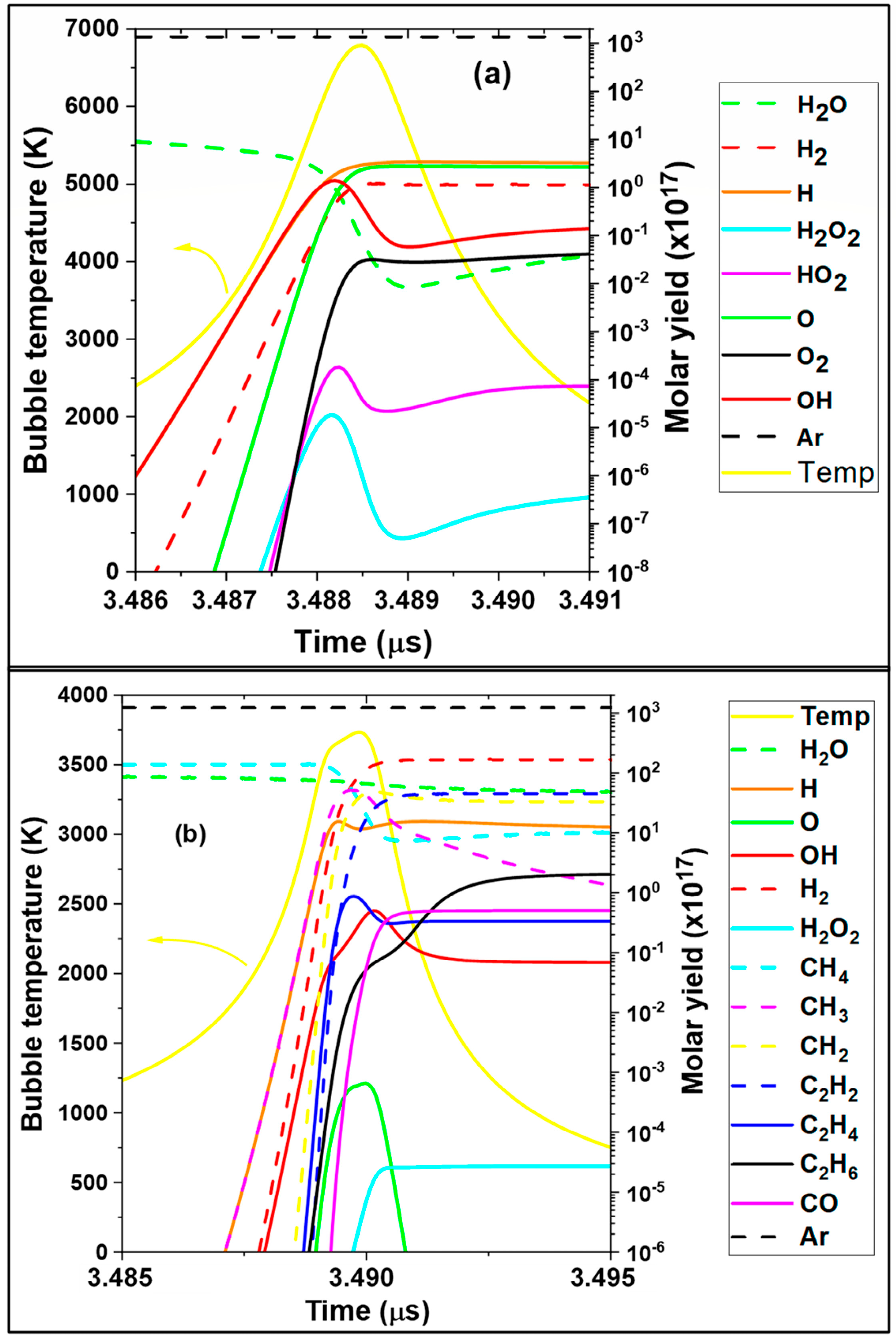
3.1. Kinetics of Bubble in Presence of Methane

In Figure 1a,b, the molar production and the temperature evolution inside the acoustic cavitation bubble are shown for Ar and Ar–CH4 (90%/10%) saturated water irradiated at 213 kHz and 1 W/cm². The time scale in Figure 1a,b is shown at around the end of bubble collapse (~3.4885 and 3.490 µs, respectively), when the initial bubble radius (R0 = 3.9 µm) is taken as that determined experimentally by Brotchi et al. (i.e., the mean ambient bubble radius of the bubble population) [34]. As it can be seen in Figure 1a, the main species produced (at the end of collapse) within an argon bubble are H (2.95 × 10⁻¹⁷ mol), OH (4.19 × 10⁻¹⁸ mol), O (2.36 × 10⁻¹⁷ mol), and H2 (1.15 × 10⁻¹⁷ mol) molecules. The predominance of these species was also observed in the different theoretical works for argon-saturated water [35,36,37]. Under these conditions (213 kHz, 1 W/cm²), the peak temperature of the bubble is 6788 K. On the other hand, in Figure 1b it can be seen that the important products are in the order: H2 (1.28 × 10⁻¹⁵ mol) > CH2 (4.79 × 10⁻¹⁶ mol) > CH3 (3.55 × 10⁻¹⁶ mol) > C2H2 (2.24 × 10⁻¹⁶ mol) > H (1.23 × 10⁻¹⁶ mol) > OH (4.88 × 10⁻¹⁸ mol) > C2H4 (4.87 × 10⁻¹⁸ mol) > CO (1.09 × 10⁻¹⁸ mol) > C2H6 (6.13 × 10⁻¹⁹ mol). Whereas, in this case, the maximal bubble temperature goes down to 3650 K (46.22% of decrease in the presence of 10% CH4). This decrease in the peak temperature is owing to the increase in heat capacity of the bubble as well as the endothermal dissociation of methane. In the presence of 10% methane (Figure 1b), the yield of hydrogen goes up by 111 fold compared to the case where the gas atmosphere is saturated only by argon (Figure 1a). This enhancement in H2 production could be ascribed mainly to the thermolysis of CH4 (Reaction 9, Table 3) and the reaction of methane with hydrogen atoms (Reaction 9, Table 3). According to Figure 1b, a slight enhancement (16%) was retrieved for OH radicals in the presence of methane, Figure 1a,b. The explication of this outcome is detailed in Section 3.3. The confrontation of the findings of Figure 1b to those of Hart et al. [21] (real system) indicates a clear discrepancy in the molar formation of C2H2, C2H4, C2H6, and CO (for Hart’s group: CO > C2H2 > C2H6 > C2H4). This difference is primarily explained by the different acoustical conditions, i.e., in the present study: 213 kHz and 1 W/cm² and for Hart’s team: 300 kHz, 2 W/cm². In addition, in our work the simulation task is performed for a single bubble (single micro-reactor) whereas Hart et al.’s obtained results are for a multi-bubble system (multiple interactions). It should be stressed here that the chemistry of the sonicated medium is affected by the solubility of the generated species from the collapsing bubbles. This means that the resulting kinetics in Figure 1b are plausibly modified, especially for the more soluble species which undergo more sonolysis before escaping outside the irradiated solution. This could be understood by knowing that the solubilities of acetylene (1.08 g/1 kg H2O, at 25 °C [38]) and ethylene in water are 39 and 5 times greater than that of carbon monoxide (0.0276 g/1 kg H2O, at 25 °C [38]), respectively. More clarifications about the bubble chemistry are given in Section 3.3 with respect to the variation in the driving ultrasound frequency. This section may be divided by subheadings. It should provide a concise and precise description of the experimental results, their interpretation, as well as the experimental conclusions that can be drawn.

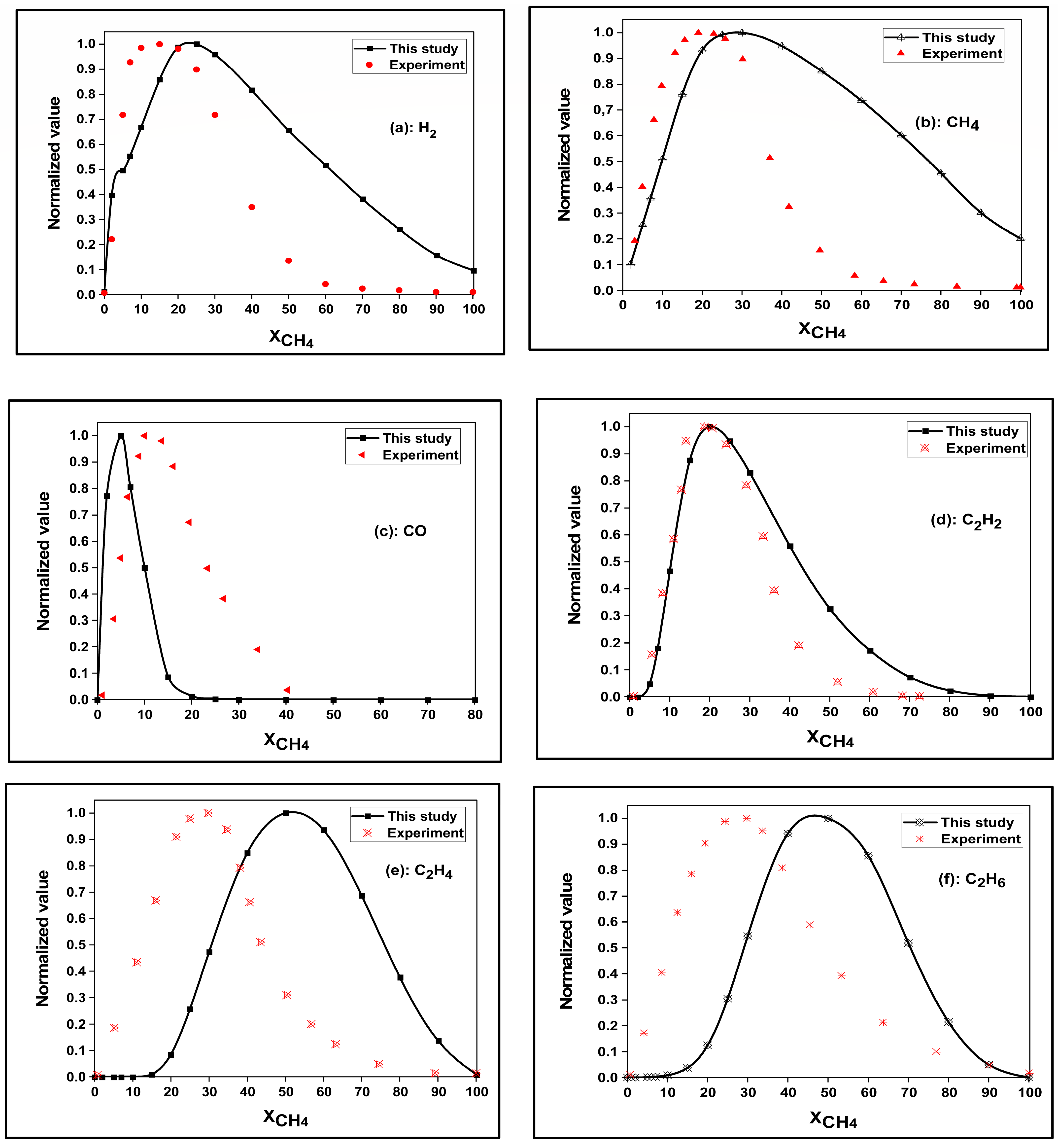
3.2. Model Efficiency

To check the viability of our model, numerical simulations of bubble sonochemistry in the presence of different CH4 proportions in argon (i.e., the saturation gas matrix) have been performed under the same experimental operating conditions of Hart et al. [f = 300 kHz, In = 2 W/cm²] [21]. Then the results of the main produced species (H2, CO, C2H2, C2H4, and C2H6) are compared with the experimental profiles using normalized yields (Figure 2a–f). The ambient bubble radius adopted for all these calculations was 3.2 µm, which is the typical value of R0 for frequencies around 300 kHz (~300–360 kHz) [18,34,39,40,41].
As can be seen in Figure 2a–f, a Gaussian tendency was retrieved for the molar yield of H2, CO, C2H2, C2H4, and C2H6, and the conversion of CH4, which is in accordance with the experimental results of Hart’s group. The same trend was also obtained in the experimental study of Henglein et al. [19,20] for the sonolysis of methane under an argon atmosphere. The Gaussian shape of the different graphs could be explained by the impact of the methane amount within the collapsing cavitation. This is because even with the decrease in bubble temperature (will be seen later) with the rise in CH4 mole fraction (increases the bubble heat capacity), the production of the various species (H2, CO, C2H2, C2H4, and C2H6) and methane conversion are found to be increased (competing effect), whereas over an optimum value [e.g., 20% CH4 for H2 formation, Figure 2a], the yield of these substances and CH4 conversion are proportionally decreased with the peak temperature of the bubble. This means that above this optimum the low bubble temperature is unable to ensure high molar production and methane conversion at the end of the bubble implosion. The same tendencies were previously retrieved in the literature works [18,23,42] at the different initial bubble compositions. For the molar production of H2, CO, C2H2, C2H4, C2H6 and CH4 conversion, our maximal values are found at 20%, 5%, 20, 50%, 50% and 30% of CH4 in the gas matrix, respectively; whereas those obtained experimentally by Hart’s group were at 15%, 10%, 20%, 30%, 30% and 20%, respectively. It should be noted that a total matching between our theoretical findings and those of Hart’s team is not expected because our results (expressed in moles) are based on a single-bubble system (micro-reactor), whereas those of Hart et al. (molar rates) are given for a real system (multi-cavitation system) where many phenomena (bubble–bubble interaction, bubbles coalescence …) are taking place. Despite that, our outcomes are very acceptable with slight discrepancies observed for the formation of ethylene and ethane, Figure 2e,f. Based on the results of Figure 2a–f, it can be concluded that the present model is accepted for modelling the effect of methane on bubble sonochemistry with the change in ultrasound frequency.

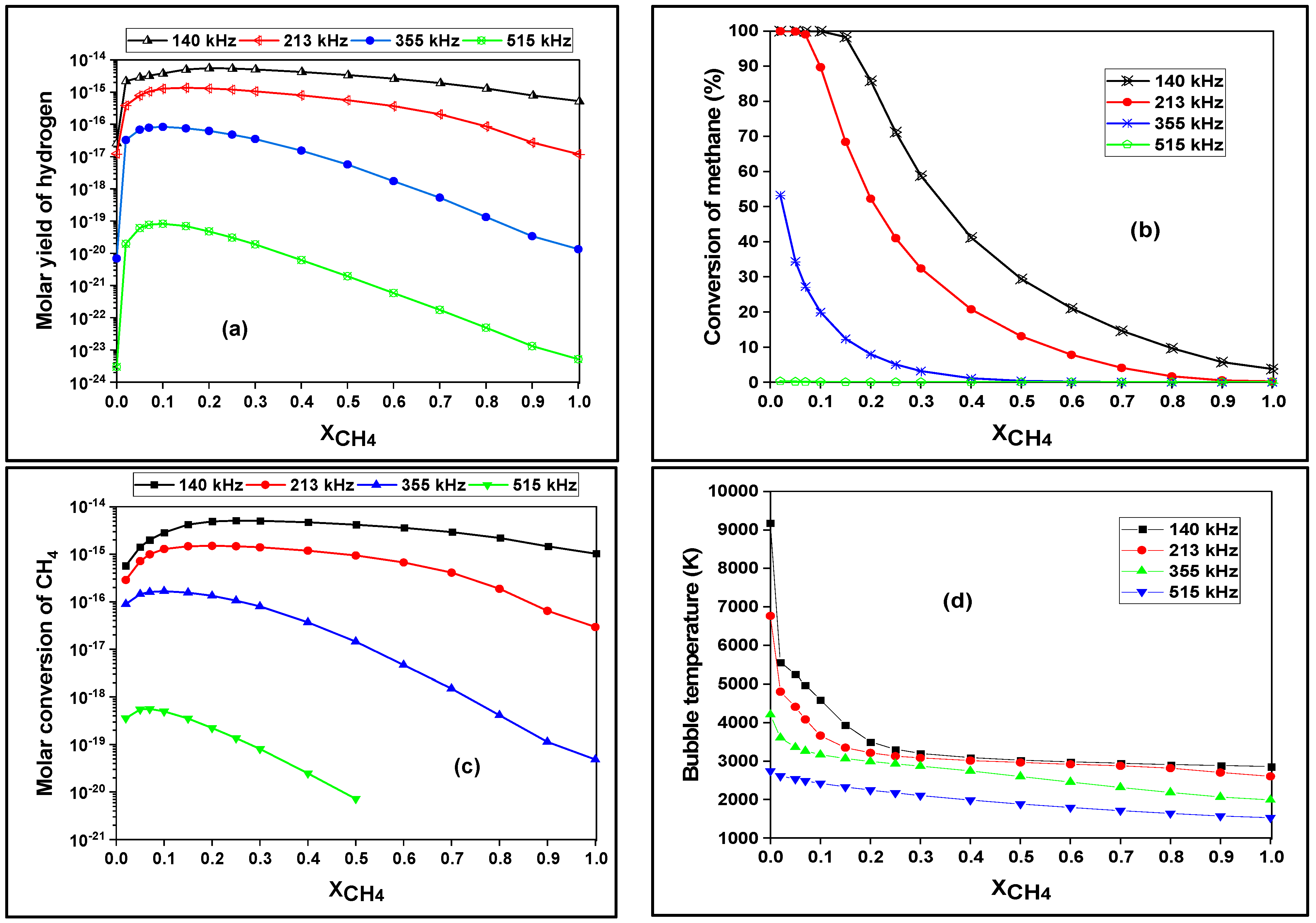
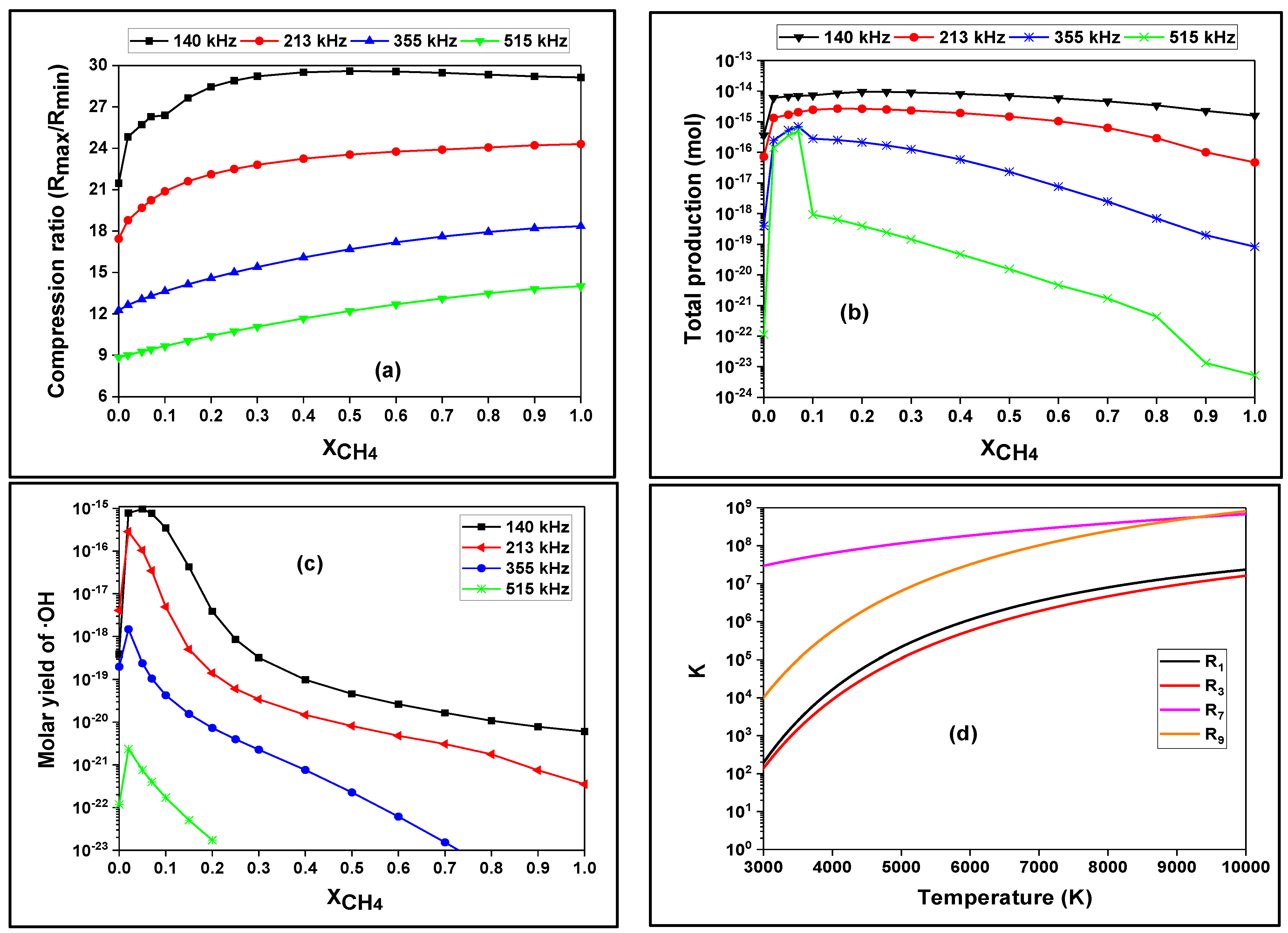
3.3. Effect of Methane Dose on the Bubble Chemistry and Dynamics

In this section, the impact of methane concentration (in the gas phase) on the sonoactivity and dynamics of a single bubble is explored with respect to the change in the wave frequency in the range from 140 to 515 kHz (Figure 3 and Figure 4). The choice of this frequency range (140–515 kHz) is based on the findings of the different experimental and theoretical works [43,44,45], indicating that the maximal sonoactivity in this is situated in this frequency range (140–515 kHz). In these simulations, the typical initial bubble radii are taken as a function of frequency as R0 = 5 µm for 140 kHz, R0 = 3.9 µm for 213 kHz [34], 3.2 µm for 355 kHz [34], 3 µm for 515 kHz [46]. These typical values are reported experimentally (in the indicated references) and confirmed theoretically in several numerical studies [37,39,41,42,47].
As it can be seen in Figure 3a, independently of the used frequency (140–515 kHz), the presence of methane (XCH4 = 0.02–1) within the oscillating bubble has a positive effect on the formation of hydrogen, where this yield (H2) is increased with the decrease in ultrasound frequency (from 515 to 140 kHz). Additionally, it is observed at 140, 213, 355, and 515 kHz that the maximal production of H2 is obtained at 20 (5.54 × 10⁻¹⁵ mol), 15 (1.37 × 10⁻¹⁵ mol), 10 (8.35 × 10⁻¹⁷ mol), and 10% (8.27 × 10⁻²⁰ mol) CH4, respectively. Above these optimums (10–20% CH4) the production of hydrogen goes down with the rise in CH4 mole fraction in the gas phase (bubble interior). These optimums (especially that at 355 kHz (10%)) are in good concordance with those obtained experimentally by Hart et al. [21] and Henglein et al. [19,20]. The same trend observed in Figure 3a was obtained previously via the sonolysis of methanol and carbon tetrachloride [18,23,48]. It is worth mentioning that the increase (at the optimum values) in molar yield of hydrogen at low frequencies (four orders of magnitude at 10% CH4, for f = 515 kHz) is greater than that retrieved at high frequencies (two orders of magnitude at 20% CH4 for f = 140 kHz), Figure 3a.
However, the maximal yields of H2 at low frequencies (8.27 × 10⁻²⁰ mol at 10% CH4 for f = 515 kHz) are very low compared to those retrieved at higher ones (6.54 × 10⁻¹⁵ mol at 20% for f = 140 kHz).
In Figure 3b, the conversion (%) of methane inside the acoustic cavitation is depicted over the frequency range from 140 to 515 kHz as a function of its (CH4) initial mole fraction (from 0 to 1) within the bubble. It is found that the highest conversions (in %) are obtained at 140 and 213 kHz (compared to those at 355 and 515 kHz), where the same methane conversion (~100%) is obtained at 140 and 213 kHz for the mole fractions of 2, 5 and 7% CH4 inside the bubble (initially). These results are corroborated in Figure 3c in terms of the molar conversion of methane, where the gap between the frequencies (especially for f > 213 kHz) is increased with the rise of the initial mole fraction of CH4 (XCH4) inside the bubble. For XCH4 > 0.5, the molar conversion of methane (inside the bubble) is suppressed. It should be stressed here that for a single-bubble system the choice of a frequency of 140 kHz is more beneficial for maximal hydrogen production and methane conversion. However, for a multi-bubble system (real system) this might not be true, because in this case (a multi-bubble system) the number density should be taken into account; therefore, the total yields of hydrogen and methane conversion are affected. In general, it is known that for a constant acoustic amplitude the number of active bubbles increased with the rise in ultrasound frequency [40,49,50,51]; this means that for a frequency greater than 140 kHz (213–515 kHz), higher production of hydrogen and conversion of methane are possibly obtained. This trend is like that found for CCl4 sonopyrolysis within acoustic bubbles, where the single-bubble conversion decreased with increasing frequency, while the bubble density increased [40]. The compromise between these two factors yields a continued increase in the overall CCl4 conversion (in solution) because of the frequency impact’s dominance on the bubbles’ number against the single-bubble yield (please see [40]).
In Figure 3d, the variation in the maximal bubble temperature is evaluated as a function of methane mole fraction over the ultrasound frequency range from 140 to 515 kHz. At first sight, it can be retrieved that the peak temperature of a bubble goes down either with the rise of wave frequency (at a fixed mole fraction of CH4), or with the increase in methane dose (at a constant frequency) inside the acoustic cavitation. Furthermore, it is found that the effect of methane mole fraction on bubble temperature (Tmax) is intensified with the decrease in ultrasound frequency. At 140, 213, 355, and 515 kHz the peak temperature goes down by 68.79 (from 9168 to 2861 K), 61.48 (from 6767 to 2606 K), 52.66 (from 4205 to 1990 K), and 44.18% (from 2741 to 1530 K), respectively. The decrease in bubble temperature with the rise in methane mole fraction inside the bubble is explained by the increased heat capacity of the bubble in the presence of methane and its endothermal dissociation (Reaction 9, Table 3) during bubble collapse. Therefore, the decrease in ultrasound frequency (more expansion) increases the encapsulated quantity of CH4, which means that its negative effect on bubble temperature is accelerated in this case. The same tendency was previously observed [18,52] in the presence of different volatile species within the implosive cavitation.
In Figure 4a, remarkably, it is seen that at each driving frequency the compression ratio is increased (35.71, 39.33, 49.73, and 58.43% at 140, 213, 355, and 515 kHz, respectively) with the rise in CH4 mole fraction (from 0 to 1), but despite that the bubble temperature was found to be decreased (Figure 3d). This outcome could be explained by the decrease in bubble internal energy (in the presence of CH4) as a result of the increase in its heat capacity (Equation (4), Table 1), enhancement of heat conduction outside the bubble (Equation (8), Table 1), and the endothermal dissociation of methane (Table 1 and Equation (9)). Therefore, according to Equation (4) (Table 1), the bubble temperature is found to be reduced proportionally with the increase in CH4 concentration. On the other hand, we observe that the compression ratio increased with the decrease in ultrasound frequency (at a constant CH4 mole fraction), so obviously this is a logical result because in this case (low frequencies) the expansion and compression of bubble are maximized with the longer acoustic period. It should be noted that of the energetic evaluation of the sono-cavitation process is of great importance for understanding the sonochemical efficiency. An entire study on the energetic efficiency of the sonolytic process (single- and multi-bubble systems) has been performed and published in our recent papers [53,54]. The single-bubble energy increased with frequency decrease and applied power increase, whereas some difference was found for the multi-bubble system [53,54].
In Figure 4b it is shown that the bubble’s total yield is enhanced in the presence of methane until an optimum threshold (depending on the applied frequency), above which this production goes down proportionally with the rise in CH4 dose inside the bubble. This decrease in the total production is clearly explained by the decrease in bubble temperature [Figure 3d]; thus, in these regions (where the total yield is decreased) the peak temperature is unable to ensure the increase in the overall production (i.e., low dissociation of water vapor and methane). However, the reduction in the total yield of bubble is amortized at low frequencies as a result of the relatively high temperatures under these circumstances.
Hydroxyl radical (OH) plays a central role in H2 production inside the bubble (via the pyrolytic reaction). Merouani et al. [32] demonstrated that H2 is primarily produced in the gas phase of bubbles via recombination of primary radicals (H + OH → O + H2, Reaction 31 of Table 2) formed by splitting water vapor molecules at the high temperature developed during the bubble’s collapse phase. This reaction is responsible for H2 generation over a wide range of sonication conditions [2,11,42,55,56]. Furthermore, when methane is present, OH is a major precursor of CH3 formation inside the bubble (CH4 + OH → CH3 + H2O, Reaction 7 of Table 3). This latter, CH3, is considered a principal source of H2 production as per Reactions 11 and 18 of Table 3 (CH3 + CH3 → C2H4 + H2 and CH3 + H → CH2 + H2).
The evolution of hydroxyl radicals as a function of methane mole fraction (inside the bubble) and the ultrasound frequency is shown in Figure 4c. First, a maximal improvement in the OH production is observed at 2% (5% for 140 kHz) CH4 for all the driving frequency, whereas over these optimums the yield of hydroxyl radicals is drastically decreased. The confrontation of Figure 4c to Figure 3a indicates that at 355 and 515 kHz and independently of CH4 mole fraction, the yield of OH radical is very low compared to that of hydrogen. For example, at 5% CH4, the molar formation of H2 is 285- and 80-fold higher than that of OH radicals, respectively, at 355 and 515 kHz. This gap goes up to three orders of magnitude at 20% CH4 for both frequencies (355 and 515 kHz). Our outcomes are in good concordance with those obtained by Hart et al. and Henglein et al. [19,20,21] at 300 kHz, where a very low production of H2O2 (resulting from the recombination of OH radicals) was obtained compared to that of H2 during the sonolysis of methane. Interestingly, at 140 and 213 kHz a relative enhancement was observed for the production of OH radicals compared to the case of 355 and 515 kHz. For example, at 140 kHz the molar yield of H2 is ~3 times greater than that of OH radicals at 2% CH4, whereas this difference goes up rapidly to 4-, 10-fold and 3 orders of magnitude, respectively, at 7, 10, and 20% CH4. Similarly, at 213 kHz, the increase in CH4 mole fraction from 2 to 20% gives an increase of ~2 fold and 3 orders of magnitude, respectively, for the formation of H2 compared to OH radicals. The analysis of Figure 3a and Figure 4c indicates the possibility of ensuring a simultaneous high production of H2 and a relatively important yield of OH radicals for methane mole fractions lower than or equal to 30 and 10% for 140 and 213 kHz, respectively. This outcome was never discussed previously in the literature. According to Table 3 (Reaction 7), the improvement of OH production at 140 and 213 kHz (in parallel to that of H2) seems to be controversial because OH radicals are supposed to be scavenged by CH4 molecules. To explain this trend, it should firstly be noted that for CH4 mole fraction ≤30% at 140 kHz and ≤10% at 213 kHz (Figure 3d) the bubble temperature under these conditions is between 3000 and 10,000 K. According to Figure 4d, it can be seen that with the increase in bubble temperature the scavenging mechanism of OH radicals (Reaction 7, Table 3) is increasingly competed by the decomposition of methane (Reaction, Table 3), thermal decomposition of water vapor (Reaction 1, Table 3), and accompanied by the decomposition of hydroxyl radicals (Reaction 3, Table 3) at a low extent. Therefore, it can be concluded that the main source of enhancing the yield of hydroxyl radicals at high bubble temperatures is the decomposition of methane, and as a result, less scavenging of OH radicals is achieved under these conditions.

4. Conclusions

In this study, the sono-formation of hydrogen from methane sonolysis in single acoustic cavitation was analyzed for the first time over a frequency range from 140 to 515 kHz, as a function of CH4 mole fraction within the oscillating bubble. It was found that independently of the adopted frequency (140–515 kHz), the presence of methane inside the bubble positively affects the formation of hydrogen (increased), which is enhanced with the decrease in the driving frequency. The production of hydrogen was found to be maximal at 20, 15, 10, and 10% CH4 at the driving frequency of 140, 213, 355, and 515 kHz, respectively. The highest conversions of methane (~100% for 2, 5 and 7% CH4) were obtained at 140 and 213 kHz. For a single-bubble system (microreactor), the adoption of 140 kHz frequency was found to be the best choice for maximal hydrogen production and methane conversion, whereas for the multi-bubble system (real process), the parameter of number density should be considered for an optimal choice of the irradiation frequency. In accordance with the experimental findings, independently of CH4 mole fraction, very low production of OH radicals was obtained at 355 and 515 kHz. Interestingly, a relative improvement in the formation of hydroxyl radicals was retrieved at 140 and 213 kHz. It has been found that for methane mole fractions lower than or equal to 30 and 10% for 140 and 213 kHz, respectively, a maximal production of H2 and a relatively important yielding of OH could be obtained simultaneously.

Author Contributions

A.D.: Conceptualization, methodology, software, validation, writing—original draft preparation. S.M.: Conceptualization, methodology, data analysis, writing—review and editing, project supervision. All authors have read and agreed to the published version of the manuscript.

Funding

This research received no external funding.

Institutional Review Board Statement

Not applicable.

Informed Consent Statement

Not applicable.

Data Availability Statement

Not applicable.

Conflicts of Interest

The authors declare no conflict of interest.

Nomenclature

Af (Ar)Pre-exponential factor of the forward (reverse) reaction, [(cm3 mol−1 s−1) for two-body reaction and (cm6 mol−2 s−1) for three-body reaction].
bf (br)Temperature exponent of the forward (reverse) reaction.
cSpeed of sound in the liquid medium, (m s−1).
CpHeat capacity concentration inside the bubble (J m−3 K−1)
Eaf (Ear)Activation energy of the forward (reverse) reaction, (cal mol−1).
fFrequency of ultrasonic wave, (Hz).
IaAcoustic intensity of ultrasonic irradiation, (W m−2).
kf (kr)Forward (reverse) reaction constant, [(cm3 mol−1 s−1) for two-body reaction and (cm6 mol−2 s−1) for three-body reaction].
MH2OMolar mass of water (kg mol−1).
m ˙ Evaporation-condensation rate of water (kg m-² s−1).
nMolar amount (mol).
pPressure inside a bubble, (Pa).
PAAmplitude of the acoustic pressure, (Pa).
PBLiquid pressure on the external side of the bubble wall, (Pa)
pmaxMaximum pressure inside a bubble (Pa).
PvVapor pressure of water, (Pa).
pAmbient static pressure, (Pa).
QEnergy transferred by heat exchange (J s−1)
RRadius of the bubble, (m).
RgIdeal gas constant (J/mol K).
RmaxMaximum radius of the bubble, (m).
R0Ambient bubble radius, (m).
tTime, (s).
TTemperature inside a bubble, (K).
TmaxMaximum temperature inside a bubble, (K).
TBulk liquid temperature, (K).
U ˙ k Production rate of the kth species (mol s−1 m−3)
VVolume of the bubble (m3)
xThermal diffusivity inside the bubble (m² s−1)
Greek letters
αAccommodation coefficient.
λΙThermal conductivity of species i (W m−1 K−1).
λμιξThermal conductivity of the mixture (W m−1 K−1).
µDynamic viscosity (Pa s).
ργDensity inside the bubble (kg m−3).
ρH2ODensity of water vapor inside the bubble (Kg m−3).
ρλDensity of liquid water, (kg m−3).
ρσατ,H2OSaturated vapor density (Kg m−3).
sSurface tension of liquid water, (N m−1).
υkiStoichiometric coefficient of the kth chemical species in the ith reaction

References

  1. Dincer, I.; Acar, C. Review and evaluation of hydrogen production methods for better sustainability. Int. J. Hydrogen. Energy 2015, 40, 11094–11111. [Google Scholar] [CrossRef]
  2. Merouani, S.; Hamdaoui, O. Correlations between the sonochemical production rate of hydrogen and the maximum temperature and pressure reached in acoustic bubbles. Arab. J. Sci. Eng. 2018, 43, 6109–6117. [Google Scholar] [CrossRef]
  3. Chibani, A.; Merouani, S.; Bougriou, C.; Hamadi, L. International Journal of Heat and Mass Transfer Heat and mass transfer during the storage of hydrogen in LaNi 5 -based metal hydride: 2D simulation results for a large scale, multi-pipes fixed-bed reactor. Int. J. Heat Mass Transf. 2019, 147, 118939. [Google Scholar] [CrossRef]
  4. Chibani, A.; Bougriou, C.; Merouani, S. Simulation of hydrogen absorption/desorption on metal hydride LaNi5-H2: Mass and heat transfer. Appl. Therm. Eng. 2018, 142, 110–117. [Google Scholar] [CrossRef]
  5. Nikolaidis, P.; Poullikkas, A. A comparative overview of hydrogen production processes. Renew. Sustain. Energy Rev. 2017, 67, 597–611. [Google Scholar] [CrossRef]
  6. Acar, C.; Dincer, I. Comparative assessment of hydrogen production methods from renewable and non-renewable sources. Int. J. Hydrog. Energy 2014, 39, 1–12. [Google Scholar] [CrossRef]
  7. Balat, M. Possible methods for hydrogen production. Energy Sources Part A Recover. Util. Environ. Eff. 2008, 31, 39–50. [Google Scholar] [CrossRef]
  8. Kothari, R.; Buddhi, D.; Sawhney, R.L. Comparison of environmental and economic aspects of various hydrogen production methods. Renew. Sustain. Energy Rev. 2008, 12, 553–563. [Google Scholar] [CrossRef]
  9. Islam, M.H.; Lamb, J.J.; Lien, K.M.; Burheim, O.S.; Hihn, J.-Y.; Pollet, B.G. Novel fuel production based on sonochemistry and sonoelectrochemistry. ECS Trans. 2019, 92, 1. [Google Scholar] [CrossRef] [Green Version]
  10. Kapdan, I.K.; Kargi, F. Bio-hydrogen Production from Waste Materials Bio-hydrogen production from waste materials. Enzyme Microb. Technol. 2006, 38, 569–582. [Google Scholar] [CrossRef]
  11. Merouani, S.; Hamdaoui, O. The sonochemical approach for hydrogen production. In Sustainable Green Chemical Processes and Their Allied Applications. Nanotechnology in the Life Sciences; Inamuddin, Asiri, A., Eds.; Springer: Berlin/Heidelberg, Germany, 2020; pp. 1–29. [Google Scholar]
  12. Islam, M.H.; Burheim, O.S.; Pollet, B.G.; Islam, H.; Burheim, O.S.; Pollet, B.G.; Islam, M.H.; Burheim, O.S.; Pollet, B.G. Sonochemical and Sonoelectrochemical Production of Hydrogen. Ultrason. Sonochem. 2018, 51, 533–555. [Google Scholar] [CrossRef] [PubMed]
  13. Adewuyi, Y.G. Sonochemistry: Environmental science and engineering applications. Ind. Eng. Chem. Res. 2001, 40, 4681–4715. [Google Scholar] [CrossRef]
  14. Tuziuti, T.; Yasui, K.; Sivakumar, M.; Iida, Y.; Miyoshi, N. Correlation between acoustic cavitation noise and yield enhancement of sonochemical reaction by particle addition. J. Phys. Chem. A 2005, 109, 4869–4872. [Google Scholar] [CrossRef] [PubMed]
  15. Mizukoshi, Y.; Nakamura, H.; Bandow, H.; Maeda, Y.; Nagata, Y. Sonolysis of organic liquid: Effect of vapour pressure and evaporation rate. Ultrason. Sonochem. 1999, 6, 203–209. [Google Scholar] [CrossRef]
  16. Buettner, J.; Gutierrez, M.; Henglein, a. Sonolysis of water-methanol mixtures. J. Phys. Chem. 1991, 95, 1528–1530. [Google Scholar] [CrossRef]
  17. Kerboua, K.; Hamdaoui, O.; Al-Zahrani, S. Sonochemical production of hydrogen: A numerical model applied to the recovery of aqueous methanol waste under Oxygen-Argon atmosphere. Environ. Prog. Sustain. Energy 2020, in press. [Google Scholar] [CrossRef]
  18. Dehane, A.; Merouani, S.; Hamdaoui, O. Methanol sono-pyrolysis for hydrogen recovery: Effect of methanol concentration under an argon atmosphere. Chem. Eng. J. 2021, 433, 133272. [Google Scholar] [CrossRef]
  19. Henglein, A. Sonolysis of carbon dioxide, nitrous oxide and methane in aqueous solution. Z. Naturforsch. B 1985, 40, 100–107. [Google Scholar] [CrossRef]
  20. Henglein, A. Chemical effects of continuous and pulsed ultrasound in aqueous solutions. Ultrason. Sonochem. 1995, 2, 115–121. [Google Scholar] [CrossRef]
  21. Hart, E.J.; Fischer, C.H.; Henglein, A. Sonolysis of hydrocarbons in aqueous solution. Int. J. Radiat. Appl. Instrum. Part C Radiat. Phys. Chem. 1990, 36, 511–516. [Google Scholar] [CrossRef]
  22. Arsentev, S.D. Sonochemical Transformations of Methane and Ethylene in Aqueous Solutions under Conditions of Cavitation. Phys. Chem. Solut. 2020, 94, 1811–1815. [Google Scholar] [CrossRef]
  23. Dehane, A.; Merouani, S.; Hamdaoui, O. Effect of carbon tetrachloride (CCl4) sonochemistry on the size of active bubbles for the production of reactive oxygen and chlorine species in acoustic cavitation field. Chem. Eng. J. 2021, 426, 130251. [Google Scholar] [CrossRef]
  24. Dehane, A.; Merouani, S.; Hamdaoui, O. Carbon tetrachloride (CCl4) sonochemistry: A comprehensive mechanistic and kinetics analysis elucidating how CCl4 pyrolysis improves the sonolytic degradation of nonvolatile organic contaminants. Sep. Purif. Technol. 2021, 275, 118614. [Google Scholar] [CrossRef]
  25. Yasui, K. Effects of thermal conduction on bubble dynamics near the sonoluminescence threshold. J. Acoust. Soc. Am. 1995, 98, 2772–2782. [Google Scholar] [CrossRef]
  26. Sochard, S.; Wilhelm, A.M.; Delmas, H. Modelling of free radicals production in a collapsing gas-vapour bubble. Ultrason. Sonochem. 1997, 4, 77–84. [Google Scholar] [CrossRef] [PubMed]
  27. Toegel, R.; Lohse, D. Phase diagrams for sonoluminescing bubbles: A comparison between experiment and theory. J. Chem. Phys. 2003, 118, 1863–1875. [Google Scholar] [CrossRef]
  28. Merouani, S.; Hamdaoui, O. Computer simulation of chemical reactions occurring in collapsing acoustical bubble: Dependence of free radicals production on operational conditions. Res. Chem. Intermed. 2015, 41, 881–897. [Google Scholar] [CrossRef]
  29. Yasui, K.; Tuziuti, T.; Kanematsu, W. Extreme conditions in a dissolving air nanobubble. Phys. Rev. E 2016, 94, 013106. [Google Scholar] [CrossRef]
  30. Touloukian, Y.S.; Liley, P.E.; Saxena, S. Thermal conductivity (Nonmetallic liquids and gases). Thermophys. Prop. Matter 1970, 3, 512. [Google Scholar]
  31. Yasui, K.; Yasui, K. Effect of volatile solutes on sonoluminescence. J. Chem. Phys. 2002, 2945, 2945. [Google Scholar] [CrossRef]
  32. Merouani, S.; Hamdaoui, O.; Rezgui, Y.; Guemini, M. Mechanism of the sonochemical production of hydrogen. Int. J. Hydrog. Energy 2015, 40, 4056–4064. [Google Scholar] [CrossRef]
  33. Yasui, K. Chemical reactions in a sonoluminescing bubble. J. Phys. Soc. Jpn. 1997, 66, 2911–2920. [Google Scholar] [CrossRef]
  34. Brotchie, A.; Grieser, F.; Ashokkumar, M. Effect of power and frequency on bubble-size distributions in acoustic cavitation. Phys. Rev. Lett. 2009, 102, 084302. [Google Scholar] [CrossRef] [PubMed]
  35. Yasui, K. Alternative model of single-bubble sonoluminescence. Phys. Rev. E 1997, 56, 6750–6760. [Google Scholar] [CrossRef]
  36. Merouani, S.; Ferkous, H.; Hamdaoui, O.; Rezgui, Y.; Guemini, M. New interpretation of the effects of argon-saturating gas toward sonochemical reactions. Ultrason. Sonochem. 2015, 23, 37–45. [Google Scholar] [CrossRef] [PubMed]
  37. Dehane, A.; Merouani, S.; Hamdaoui, O.; Alghyamah, A. Insight into the impact of excluding mass transport, heat exchange and chemical reactions heat on the sonochemical bubble yield: Bubble size-dependency. Ultrason. Sonochem. 2021, 73, 105511. [Google Scholar] [CrossRef]
  38. Lide, D.R.; Haynes, W.M.M.; Baysinger, G.; Berger, L.I.; Kehiaian, H.V.; Roth, D.L.; Zwillinger, D.; Frenkel, M.; Goldberg, R.N. CRC Handbook of Chemistry and Physics, 90th ed.; Internet Version; CRC Press: Boca Raton, FL, USA, 2010. [Google Scholar]
  39. Dehane, A.; Merouani, S.; Hamdaoui, O.; Alghyamah, A. A complete analysis of the effects of transfer phenomenons and reaction heats on sono-hydrogen production from reacting bubbles: Impact of ambient bubble size. Int. J. Hydrog. Energy 2021, 46, 18767–18779. [Google Scholar] [CrossRef]
  40. Dehane, A.; Merouani, S.; Hamdaoui, O.; Ashokkumar, M. An alternative technique for determining the number density of acoustic cavitation bubbles in sonochemical reactors. Ultrason. Sonochem. 2022, 82, 105872. [Google Scholar] [CrossRef]
  41. Yasui, K.; Tuziuti, T.; Lee, J.; Kozuka, T.; Towata, A.; Iida, Y. The range of ambient radius for an active bubble in sonoluminescence and sonochemical reactions. J. Chem. Phys. 2008, 128, 184705. [Google Scholar] [CrossRef]
  42. Merouani, S.; Hamdaoui, O. The size of active bubbles for the production of hydrogen in sonochemical reaction field. Ultrason. Sonochem. 2016, 32, 320–327. [Google Scholar] [CrossRef]
  43. Jiang, Y.; Petrier, C.; Waite, T.D. Sonolysis of 4-chlorophenol in aqueous solution: Effects of substrate concentration, aqueous temperature and ultrasonic frequency. Ultrason. Sonochem. 2006, 13, 415–422. [Google Scholar] [CrossRef] [PubMed]
  44. Beckett, M.A.; Hua, I. Elucidation of the 1,4-dioxane decomposition pathway at discrete ultrasonic frequencies. Environ. Sci. Technol. 2000, 34, 3944–3953. [Google Scholar] [CrossRef]
  45. Koda, S.; Kimura, T.; Kondo, T.; Mitome, H. A standard method to calibrate sonochemical efficiency of an individual reaction system. Ultrason. Sonochem. 2003, 10, 149–156. [Google Scholar] [CrossRef]
  46. Lee, J.; Ashokkumar, M.; Kentish, S.; Grieser, F. Determination of the size distribution of sonoluminescence bubbles in a pulsed acoustic field. J. Am. Chem. Soc. 2005, 127, 16810–16811. [Google Scholar] [CrossRef] [PubMed]
  47. Dehane, A.; Merouani, S.; Hamdaoui, O. Theoretical investigation of the effect of ambient pressure on bubble sonochemistry: Special focus on hydrogen and reactive radicals production. Chem. Phys. 2021, 547, 111171. [Google Scholar] [CrossRef]
  48. Rassokhin, D.N.; Kovalev, G.V.; Bugaenko, L.T. Temperature Effect on the Sonolysis of Methanol-water Mixtures. J. Am. Chem. Soc. 1995, 1984, 344–347. [Google Scholar] [CrossRef]
  49. Kerboua, K.; Hamdaoui, O. Void fraction, number density of acoustic cavitation bubbles, and acoustic frequency: A numerical investigation. J. Acoust. Soc. Am. 2019, 146, 2240. [Google Scholar] [CrossRef] [PubMed]
  50. Merouani, S.; Ferkous, H.; Hamdaoui, O.; Rezgui, Y.; Guemini, M. A method for predicting the number of active bubbles in sonochemical reactors. Ultrason. Sonochem. 2014, 22, 51–58. [Google Scholar] [CrossRef] [PubMed]
  51. Dehane, A.; Merouani, S.; Chibani, A.; Hamdaoui, O.; Yasui, K.; Ashokkumar, M. Estimation of the number density of active cavitation bubbles in a sono-irradiated aqueous solution using a thermodynamic approach. Ultrasonics 2022, 126, 106824. [Google Scholar] [CrossRef]
  52. Gireesan, S.; Pandit, A.B. Modeling the effect of carbon-dioxide gas on cavitation. Ultrason. Sonochem. 2017, 34, 721–728. [Google Scholar] [CrossRef]
  53. Dehane, A.; Merouani, S.; Hamdaoui, O. Chapter 2—The energy forms and energy conversion. In Energy Aspects of Acoustic Cavitation and Sonochemistry; Hamdaoui, O., Kerboua, K., Eds.; Elsevier: Amsterdam, The Netherlands, 2022; pp. 23–35. ISBN 978-0-323-91937-1. [Google Scholar]
  54. Dehane, A.; Merouani, S.; Hamdaoui, O. Chapter 9—Energy Controlling Mechanisms: Relationship with Operational Conditions; Hamdaoui, O., Kerboua, K., Eds.; Elsevier: Amsterdam, The Netherlands, 2022; pp. 145–155. ISBN 978-0-323-91937-1. [Google Scholar]
  55. Merouani, S.; Hamdaoui, O.; Rezgui, Y.; Guemini, M. Computational engineering study of hydrogen production via ultrasonic cavitation in water. Int. J. Hydrog. Energy 2016, 41, 832–844. [Google Scholar] [CrossRef]
  56. Kerabchi, N.; Merouani, S.; Hamdaoui, O. Relationship between liquid depth and the acoustic generation of hydrogen: Design aspect for large cavitational reactors with special focus on the role of the wave attenuation. Int. J. Green Energy 2019, 16, 423–434. [Google Scholar] [CrossRef]
Figure 1. Bubble chemistry and temperature evolution at around the end of the bubble collapse for: (a) argon saturated water; and (b) argon–methane (XCH4 = 0.1) saturated water. Ultrasound frequency (f): 213 kHz, acoustic intensity (In): 1 W/cm², liquid temperature: 20 °C.
Energies 16 00443 g001
Figure 2. Comparison of our results (molar yield for a single bubble) with the experimental findings of Hart et al. (production rates) [21] for the sonochemical formation of H2, CO, C2H2, C2H4, and C2H6 and the conversion of methane at f = 300 kHz and In = 2 W/cm² under Ar–CH4 atmosphere (XCH4 = 0–100%).
Energies 16 00443 g002
Figure 3. Effect of initial methane mole fraction (inside the bubble) and ultrasound frequency (140–515 kHz) on: (a) the molar evolution of hydrogen; (b) methane conversion (%); (c) molar conversion of CH4; and (d) the variation in bubble temperature (K).
Energies 16 00443 g003
Figure 4. Impact of initial methane mole fraction and wave frequency (140–515 kHz) on: (a) compression ratio; (b) total bubble yield; and (c) molar production of OH radicals. (d) Evolution vs. temperature of the rate constants of Reactions 1, 3, 7, and 9 of Table 3, units: m3 mol−1 s−1 (two-body reaction), m6 mol−2 s−1 (three-body reaction).
Energies 16 00443 g004
Table 1. Principal equations of the model (see detail in Refs. [23,24]) *.
  • Bubble dynamics:
( 1 R ˙ C + m ˙ C ρ L ) R R ¨ + 3 2 R ˙ 2 ( 1 R ˙ 3 C + 2 m ˙ 3 C ρ L )
= 1 ρ L ( 1 + R ˙ C ) [ P B ( t ) P A sin ( 2 π f ( t + R C ) ) P ] + m ¨ R ρ L ( 1 R ˙ C + m ˙ C ρ L ) + m ˙ ρ L ( R ˙ + m ˙ 2 ρ L + R ˙ m ˙ 2 C ρ L )
+ R C ρ L d P B d t
(1)
 -
Pressure at the external bubble wall:
P B ( t ) = P ( t ) 2 σ R 4 μ R ˙ R (2)
 -
Bubble pressure and Temperature:
P ( t ) = nR g T V nb + an 2 V 2 (3)
T = ( E + an 2 V ) C v n t (4)
2.
Mass transfer (water vapor and methanol condensation and evaporation):
m ˙ = α { P s a t , i [ R ] P i } 2 π T [ R ] R g M i i = H 2 O (5)
3.
Heat transfer (thermal conduction):
Q ˙ = 4 π R 2 λ mix ( T l i q T ) L t h (6)
L t h = m i n { R π , R χ R ˙ } (7)
λ mix = λ H 2 O ( T ) ( n H 2 O n t ) + λ Ar ( T ) ( n Ar n t ) + λ CH 4 ( T ) ( n CH 4 n t ) (8)
4.
Internal bubble energy:
Δ E = P ( t ) Δ V ( t ) + 4 π R 2 Δ t   m ˙ , H 2 O M H 2 O e H 2 O + 4 π R 2 Δ t λ ( T liq T ) L th - 4 3 π R 3 Δ t i = 1 n Δ H i r i (9)
5.
Change in species quantities (mol)
  -
For H2O:
n H 2 O ( t + Δ t ) = n H 2 O ( t ) + 4 π R 2 Δ t m ˙ , H 2 O M H 2 O + V Δ t U ˙ H 2 O (10)
  -
For other species k (except Ar):
  n k ( T + Δ t ) = n k ( T ) + V   Δ t   U ˙ k (11)
where:
U k ˙ = 1 V dn k dt i = 1 I ( υ υ ) r i                           ( k = 1 ,   ,   K ) (12)
  r i = k fi k = 1 K [ X k ] υ ki k ri k = 1 K [ X k ] υ ki (13)
  k fi = A fi T b fi   exp ( - E a fi R g T ) (14)
k ri = A ri T b ri   exp ( - E a ri R g T )   (15)
* Variables description: dots denoted here time derivative (d/dt), R is the bubble radius, C is the sound speed in the medium (water), ρL is the liquid density, m   ˙ is the net rate of evaporation per unit area and unit time and P is the ambient static pressure. PA is the acoustic amplitude (linked to the acoustic intensity Ia by: PA = (2IaρLC)1/2), PB(t) is the liquid pressure at the liquid side of the bubble, P(t) is the pressure inside the bubble. σ is the surface tension, μ is the liquid viscosity), f is the sound frequency, Pv is the vapor pressure within the bubble, a and b (in Equations (3) and (4)) are the Van der Waals constants (given in [29]), Rg is the universal gas constant. V is the volume of the bubble [V = 4/3(πR3)], T is the temperature inside the bubble, E is the internal bubble energy, Psat[R] is the saturated vapor pressure (calculated by using Antoine’s equation) at the interface temperature T[R] = Tliq,, MH2O is the molecular weight of water vapor. ‘α’ is the accommodation coefficient (given in [17]). λmix, χ and Lth are the heat conductivity, thermal diffusivity of the gas mixture and the thickness of the thermal boundary layer, respectively. [Individual λi of gases [29,30,31]: λH2O(T) = 9.967213 × 10⁻⁵T − 1.1705 × 10⁻², λAr(T) = 3.5887 × 10⁻⁵T + 6.81277 × 10⁻³, λCH4 (T) = −0.0017 + 1.0 × 10⁻⁴T + 7.0 × 10⁻⁸T² , χ = [λmix/Cp]. Cp is the heat capacity concentration (J m−3 K−1) for H2O, Ar and CH4 mixture, Cv is the molar heat of gases and vapor in the bubble [Cv = (3/2)Rg for monoatomic gases (Ar, H…), (5/2)Rg for diatomic gases (O2, N2, …) and (6/2)Rg for triatomic gases]. ΔHi and ri are the enthalpy change and the rate of the ith reaction, respectively, and eH2O is the energy transported by 1 mole of an evaporating or condensing water vapor [e,H2O = Cv,H2OT],   U ˙ i (   U ˙ k ) is the production rate of H2O (kth species) within the bubble.
Table 2. Scheme of the possible chemical reactions inside a collapsing Argon bubble [32,33]. M is the third Body. A is in (m3 mol−1 s−1) for two-body reaction [(m6 mol−2 s−1) for a three-body reaction], and Ea is in (KJ mol−1) and ∆H in (KJ mol−1).
ReactionAnEaΔH
1H2O + M → H + OH + M1.912 × 107−1.8328.35508.82
2O2+M → O + O + M4.515 × 1011−0.6428.44505.4
3OH + M → O + H+ M9.88 × 1011−0.7424.43436.23
4H + O2 → O + OH1.915 × 1080.03.9369.17
5H + O2 + M → HO2 + M1.4750.60.0−204.80
6O + H2O → OH + OH2.972.023.2172.59
7HO2 + H → H2 + O21.66 × 1070.01.97 × 10−1−239.67
8HO2 + HOH + OH7.079 × 1070.07.06 × 10−2−162.26
9HO2 + O → OH + O23.25 × 1070.00.0−231.85
10HO2 + OH → H2O + O22.89 × 1070.0−1.19 × 10⁻¹−304.44
11H2+M → H + H + M4.577 × 1013−1.424.98444.47
12O + H2 → H + OH3.82 × 1060.01.98.23
13OH + H2 → H + H2O2.16 × 1021.528.25 × 10−1−64.35
14H2O2 + O2 → HO2 + HO24.634 × 1010−0.3512.12175.35
15H2O2 + M → OH + OH +M2.951 × 1080.011.59217.89
16H2O2+H → H2O+OH2.410 × 1070.09.5 × 10−1−290.93
17H2O2 + H → H2 + HO26.025 × 1070.01.9−64.32
18H2O2 + O → OH + HO2 9.5502.09.5 × 10−1−56.08
19H2O2 + OH → H2O + HO21.0 × 1060.00.0−128.67
20H + OH + M → H2O + M 2.2 × 10¹⁰−2.00.0−508.82
21O + O + M → O2 + M 6.165 × 10³−0.50.0−505.4
22O + H + M → OH + M 4.714 × 10⁶−1.00.0−436.23
23O + OH → H + O2 5.481 × 1050.39−7.01 × 10⁻²−69.17
24HO2 +M → H + O2 + M 3.09 × 1060.5311.7204.80
25OH+OH → O + H2O 1.465 × 10−12.11−6.94 × 10⁻¹−72.59
26H2 + O2 → HO2+ H 3.164 × 1060.3513.3239.67
27OH + OH → HO2 + H 2.027 × 1040.728.8162.26
28OH+O2 → HO2 + O 3.252 × 1060.3312.75231.85
29H2O + O2 → HO2 + OH 5.861 × 1070.2416.53304.44
30H + H + M → H2 + M 1.146 × 10⁸−1.681.96 × 10−1−444.47
31H + OH → O + H2 2.667 × 10−22.651.17−8.23
32H + H2O → OH + H2 2.298 × 1031.404.3864.35
33HO2 + HO2 → H2O2 + O2 4.2 × 1080.02.87−175.35
34OH + OH + M → H2O2 + M 1.0 × 10²−0.370.0−217.89
35H2O + OH → H2O2 + H 1.269 × 1021.3117.08290.93
36H2 + HO2 → H2O2 + H 1.041 × 1050.705.7464.32
37OH + HO2 → H2O2 + O 8.66 × 10−32.684.4556.08
38H2O + HO2 → H2O2 + OH 1.838 × 1040.597.4128.67
Table 3. Scheme of the possible chemical reactions inside a collapsing Ar–CH4-bubble [32,33]. M is the third Body. A is in (m3 mol−1 s−1) for two-body reaction [(m6 mol−2 s−1) for a three-body reaction], and Ea is in (KJ mol−1) and ∆H in (KJ mol−1).
ReactionAnEaΔH
1H2O+M → H + OH + M1.912 × 107−1.8328.35508.82
2O2 + M → O + O + M4.515 × 1011−0.6428.44505.4
3OH + M → O + H + M9.88 × 1011−0.7424.43436.23
4H + O2 + M → HO2 + M1.4750.60.0−204.80
5H2 + M → H + H+ M4.577 × 1013−1.424.98444.47
6H2O2 + M → OH + OH + M2.951 × 1080.011.59217.89
7CH4 + OH → CH3 + H2O0.192.48.81−57.69
8CH4 + H → CH3 + H21.313 × 10−23.033.613.33
9CH4 + M → CH3 + H+ M1.04 × 10120.0402.97439.27
10CH3 + CH3 +M → C2H6 + M k0
              k
1.27 × 1029
3.614 × 10⁷
−7.0
0
11.55
0.0
−376.66
11CH3 + CH3 → C2H4 + H21.0 × 1080.0133.76−240.34
12C2H4+ M → C2H2 + H2 + M9.33 × 10100.038.8175.74
13O + C2H2 → CH2 + CO4.086 × 1021.57.07−197.51
14CH2 + O → CO + H24.818 × 1070.00.0−750.09
15CO + O2 → CO2 + O 2.529 × 1060.0199.44−33.83
16C2H2 + OH → CO + CH34.84 × 10−104.08.39−229.51
17CH2 + CH2 → C2H2 + 2H2.0 × 1080.044.99−116.64
18CH3 + H → CH2 + H2 2.0 × 1080.063.126.02
19O + O + M → O2 + M 6.165 × 10³−0.50.0−505.4
20HO2 + M → H + O2 + M 3.09 × 1060.5311.7204.80
21H + H + M → H2 + M 1.146 × 10⁸−1.681.96 × 10−1−444.47
22OH + OH + M → H2O2 +M 1.0 × 10²−0.370.0−217.89
23CH3 + H + M → CH4 + M k0
             k
1.42 × 10²¹
1.27 × 10¹⁰
−4.8
−0.6
10.22
1.6
−439.27
Disclaimer/Publisher’s Note: The statements, opinions and data contained in all publications are solely those of the individual author(s) and contributor(s) and not of MDPI and/or the editor(s). MDPI and/or the editor(s) disclaim responsibility for any injury to people or property resulting from any ideas, methods, instructions or products referred to in the content.

