Article

Analyses of Interpolant Ion Effects on Smart Water Core Flooding in Carbonate

by
Ladislane dos Santos Bastos
1,
Igor Emanuel da Silva Lins
1,
Gloria Meyberg Nunes Costa
1 and
Silvio Alexandre Beisl Vieira de Melo
1,2,*
1
Programa de Pós-Graduação em Engenharia Industrial, Escola Politécnica, Universidade Federal da Bahia, Rua Aristides Novis, 2, Federação, Salvador 40210-630, Brazil
2
Centro Interdisciplinar em Energia e Ambiente, Campus Universitário da Federação/Ondina, Universidade Federal da Bahia, Rua Barão de Jeremoabo, S/N, Ondina, Salvador 40170-115, Brazil
*
Author to whom correspondence should be addressed.
Energies 2023, 16(1), 446; https://doi.org/10.3390/en16010446
Submission received: 12 November 2022 / Revised: 12 December 2022 / Accepted: 21 December 2022 / Published: 30 December 2022
(This article belongs to the Special Issue Advanced Research and Techniques on Enhanced Oil Recovery Processes)

Abstract

:
Smart water flooding (SWF) is a promising enhanced oil recovery (EOR) technique due to its economic advantages. For this process, wettability alteration is the most accepted controlling effect that leads to increased recovery factors (RFs). The main objective of this work is to investigate how the relative permeability curves’ interpolant affects the SWF mechanisms’ assessment. Wettability alteration is described by shifting these curves in simulations. Numerical simulations of core flooding tests are applied to carbonate at 114.4 °C. A comparison of oil recovery factor (RF), pH and effluent composition is performed for different injection approaches. Mg2+ and SO42− are the interpolant ions and the salinity levels range from 30 to 1 kppm. A simulation of 24 scenarios, 12 for each type of interpolant, is presented. Results show that RF changes significantly, due to salinity and composition, for each interpolant. This has a relevant influence on the interpolant. The greater the dilution, the smaller the effect of the interpolant and brine composition on the recovery estimates. When considering SO42− as an interpolant, the trend is that divalent rich brine (DV) has a higher recovery factor. In contrast, when Mg2+ is the interpolant, DV tends to have a lower recovery. The analysis of ionic exchange and pH variation corroborate the wettability alteration behavior. A pH increase was observed in all scenarios, regardless of the salinity, ion composition or interpolant variation. Also, monitoring the CH3COO-X reduction and SO4-X2 increase equivalent fractions indicated the ion exchange mechanism as being well represented in all simulations. In addition, the results emphasize that even at very low concentrations, SO42− plays a fundamental role in initiating the ion exchange process that culminates in the wettability alteration as a consequence of smart water injection.

1. Introduction

Waterflooding is the most commonly used method in oil fields for additional oil recovery after reservoir depletion. This method consists of maintaining or restoring the reservoir pressure and displacing the oil to the producing well by this driving force. It is a well-established, low-cost, and environmentally friendly method. However, high values of residual oil saturation are observed [1,2]. Carbonate rocks represent a large portion of the world’s oil reservoirs (estimated at 60%), including 80% of the Middle East oil-bearing formations that accounts for approximately 75% of global oil production, so it has gained the attention of many researchers [3,4]. However, some challenges have been identified when analyzing oil recovery in this type of mineral: complex heterogeneity, fractured reservoirs, low recovery compared to sandstone results, and a tendency to a neutral or oil-wet state [3,4,5,6]. Especially in carbonate rocks, waterflooding has not been a recommended recovery method, as it is necessary to overcome high capillary forces to recover a low volume of oil [1,6]. Xu et al. (2020) [4] highlights the importance of further research to develop and understand EOR methods in carbonate reservoirs.
Among the methods recently investigated for these systems, smart water flooding (SWF) is easily implemented because it is based on waterflooding facilities and does not require adding any expensive chemicals [7]. This enhanced oil recovery method uses water with optimized composition, i.e., both the salinity and ionic composition of injected water (typically seawater or produced water) are modified to improve the production indices. Other names have also been used for this technique, such as ion-tuned or engineered water flooding. Despite being a nomenclature treated separately by some authors, low salinity water is also termed smart water based only on the reduction of salt concentration. Promising results from smart water flooding have been observed in laboratory tests and field applications. Although smart water injection has already been successfully applied in sandstone reservoirs, field tests in carbonate reports are limited. Yousef et al. (2011) [8], Yousef et al. (2011) [9], Yousef et al. (2012) [10] and Rassenfoss (2016) [11], highlight the efforts of the Saudi Arabian Oil Company research center to investigate this type of process applied to carbonate reservoirs. However, the applicability as a recovery method in reservoirs is still not widely observed, which is justified by Hao et al. (2019) [12] due to the existing gaps related to understanding the SWF mechanisms in this type of mineralogy. There is still much discussion about the exact mechanisms that lead to improving recovery, especially when carbonate rocks are involved [2,13,14,15,16]. Egbe et al. (2021) [3] and Awolayo and Sarma (2017) [17] highlight that the carbonate’s heterogeneous nature makes it more difficult to understand the oil recovery mechanisms. It occurs because there is high bonding energy to carbonate rocks and oil components in reservoirs predominantly composed of calcite, dolomite and magnesite.
Wettability alteration from oil-wet to water-wet is the main effect on carbonates observed. It has been widely accepted due to different mechanisms: multiple ion exchanges, mineral dissolution leading to a pH increase and fines migration, electrical double layer expansion, interfacial tension reduction, and microdispersions formation [3]. In turn, the injection of water with a projected composition, can disturb the established chemical equilibrium between oil, rock and brine in the porous medium [15,18,19]. In this context, experimental investigation has also demonstrated the divalent ions Ca2+, Mg2+ and SO42− are potential determining ions (PDI) to promote oil detachment from the rock surface and alter wettability and oil recovery due to multiple ion exchanges [2,20,21,22]. It is proposed that sulfate present in the injected water tends to adsorb on the carbonate surface, which is positively charged in the presence of the formation water. Due to this adsorption of negative ions, calcium cations can approximate the rock and form a complex with the carboxylic acids in the oil, releasing them from the mineral. And at high temperatures (>90 °C), magnesium cations can replace Ca2+ [23,24,25].
As experimental investigations are time-consuming and expensive, simulation of recovery methods has been an important tool for evaluating new techniques before implementation on a field scale. For modeling EOR methods, oil recovery and displacement mechanisms in the porous medium must be described through numerical formulations. For instance, transport phenomena laws, such as Darcy’s law, material and energy balance equations, chemical reactions, equations of state, and other equations that mimic different reservoir phenomena [25]. Usually, wettability alteration has been considered as a basis for building SWF simulation models [2,21,22,26]. Rock wettability influences the residual saturation of the phases and the relative permeability [17]. Therefore, in most numerical studies, the wettability alteration phenomenon is represented through the water–oil relative permeability curves that are provided as input data for the simulations [2,10,26,27].
These curves are built from the experimental determination of the extreme permeability points for different injected salinity brines and then fit through some model, such as the JBN method, which defines the shape of the curve between these points [27,28]. Different water–oil relative permeability curves are provided, each associated with a wettability state specified by an interpolant parameter. This interpolation criterion correlates the interpolant’s current concentration with the system’s wettability condition [29]. Different interpolation criteria can also be considered, such as mineral volume fraction, ion concentration in the aqueous phase, or ion-exchange equivalent fraction on the rock surface [30]. During the simulation, this interpolation parameter varies as a function of time and space, and may assume intermediate values between the extremes specified for the provided curves. Therefore, it is necessary to interpolate to obtain the relative permeability value corresponding to this intermediate condition.
Dang (2015) [25] criticizes the use of the total concentration of salts (TDS) as an interpolant because it is not enough to represent the process of smart water flooding. So, using the ion concentration in the aqueous phase is more suitable than TDS for a better numerical adjustment of phenomena in the porous medium. Most works that use this approach adopt the ion equivalent fraction on the rock surface as an interpolant of the relative permeability curves [13,17,31], but without a clear explanation. Specifically for carbonates, the most used interpolant is the SO42− or Mg2+ equivalent fraction on the rock surface, represented by SO4-X2 or Mg-X2 [3,13,31,32]. But experimentally, it is a complex variable to be quantified because it represents the ions that adhere to the rock surface and not a variable that can be determined from the effluent analysis.
Kadeethum et al. (2017) [33] give an example of a few studies that consider aqueous phase concentration as an interpolant. In this case, Ca2+ was the ion selected to mimic a sandstone core’s wettability alteration. The authors use the simulator to perform a history-matching of the SWF experiment and then extend the model also to analyze the field scale. In their results, they observed that different combinations of parameters, mainly regarding to relative permeability, can adjust lab simulation results, showing that uncertainties are included in EOR simulations. Interestingly, they indicate that the heterogeneity of the reservoir model is a parameter that influences the values of the interpolant used by them and, consequently, the production estimates obtained. Recently, Moradpour et al. (2020) [34] used sulfate in water as an interpolant in their numerical study of smart water injection into carbonates. However, like most authors, their objective was only to use this interpolant for a historical matching of core flooding experimental results and then a sensitivity analysis of SWF parameters.
Although the selected interpolation criterion usually fits the base case of sensitivity analysis studies from specific experimental conditions and results, there is no assessment of whether other studied scenarios from the variation of parameters of this tuned case are adequately represented. Studies that compare simulations with different interpolants and discuss their influence on the mechanisms have not been identified, as the present study proposes. Kadeethum et al. (2017) [33], assessed the extrapolation of laboratory results to field scale, emphasizing that simulation uncertainties can lead to misleading profit predictions from SWF projects. Therefore, simulation parameters and models must be carefully selected to minimize uncertainties, such as those from the choice of different interpolants.
In this work, a smart water flooding simulation was carried out in a carbonate oil reservoir. The state-of-the-art reports some papers about experimental evaluation of the smart water injection into carbonates and modeling and simulation [2,17,20]. However, little has been found about the relative permeability curves’ interpolant influence on SWF simulations since it directly affects the estimation of the recovery curves. It is essential to underline that the relative permeability mimics the effects of wettability alteration. Therefore, the present study differs from the literature because it also considers the gaps in the modeling and simulation of smart water injection into carbonates. The novelty is using an ion concentration in the aqueous phase as an interpolation criterion, different from the ion-exchange equivalent fraction on the rock surface, which has been widely adopted. Furthermore, two other salt ions (Mg2+ and SO42−) were chosen as criteria for interpolating relative permeability curves to investigate how the interpolant interferes with interpreting the simulated mechanism and, consequently, understanding the true potential of SWF to be applied by oil companies.
For this reason, varying the interpolating factor, this paper proposes to analyze how the wettability alteration is represented and influenced by water salinity and ion composition during SWF in carbonates. This is done by monitoring the oil recovery factor and the effluent’s composition and pH. The interpolant was varied together with the simulation of brines with salinity levels ranging from 30 to 1 kppm and three different water compositions: standard water (STD—with seawater compatible composition), monovalent-rich water (MV), and divalent-rich water (DV).

2. Methodology

In this work, a detailed simulation using a compositional simulator, GEM®, developed by Computer Modeling Group (CMG), investigates smart water core flooding in a carbonate system. The required data and the simulated scenarios are presented as follows.

2.1. Core Flooding Modeling

A carbonate core composed of calcite (50% v/v) and dolomite (50% v/v), 1.5” diameter and 12” length, was analyzed in this study. It is a homogeneous and isotropic core whose rock compressibility is 4.0 × 10⁻⁶ psi−1, the porosity is 0.2 at any point in the sample, and the permeability is also 200 mD in any direction. The reservoir pressure and temperature conditions used in the core flooding simulation were 1900 psi and 114 °C, respectively. The initial water saturation in the core was set at 0.0894, considering connate water, whose composition is shown in Table 1. Additionally, at 1900 psi and 114 °C, this brine has a density of 68.90 lb/ft3, a viscosity of 0.469 cP, and a pH 4.9.
Live oil was used in this study. Table 2 provides this oil’s composition and properties, determined experimentally by Sequeira (2006) [35].
Three chemical reactions are required to simulate smart water flooding: aqueous reactions, mineral dissolution/precipitation reactions, and ion-exchange reactions. Considering the presence of CO2 in the recombined oil, the carbonic acid formation (aqueous reactions) was included in the simulation model, as well as the salts dissolution in the aqueous phase (aqueous reactions) and the mineral dissolution and precipitation reactions of both calcite and dolomite (mineral reactions). Typically, ion exchanges provide the wettability alteration. So, for carbonates, ion sulfate adheres to the rock surface, and the ion exchange reaction should be included in the simulation model (ion exchange reaction). Details of all the reactions involved and the equilibrium constants, as well as models used for phase properties estimates, are provided in Table S1 and Equations (S1)–(S17) of the Supplementary Materials.
The core was modeled using a cartesian geometry divided into 30 equal grids (Figure 1). The injector and production wells were placed in the first and last grid blocks.
Waterflooding was simulated for an injection flow rate of 0.0006 bbl/day (reservoir condition) during the five days simulated, restricting the maximum pressure at the core inlet to 1950 psi. The pressure at the core outlet was maintained at 1901 psi, establishing a daily production limit of 0.001 barrels of liquid. These conditions were used for all simulated scenarios, described in the next section.

2.2. Simulated Scenarios

Synthetic seawater (STD) was chosen as the base composition of injection water for the core flooding simulation. Brine compositions were prepared by 3-, 6- and 30-times dilutions, named STD3x, STD6x and STD30x, respectively. Two additional brine compositions have also been adopted, departing from STD: one with only monovalent cations—named MV— and the other with divalent cations—named DV. The literature has emphasized the role of divalent cations in the smart water injection process. Some authors have experimentally investigated the use of brines with a variation of these ion concentrations to obtain typical bines rich in specific ions [36,37]. The present work complements the authors’ observations through a numerical study, if any of these brines are used. In both cases, MV and DV maintain the total salt concentration of the STD. Similarly, brines diluted 3-, 6- and 30-times were obtained based on MV and DV composition. The ionic concentrations of all brines used in this study are summarized in Table 3.
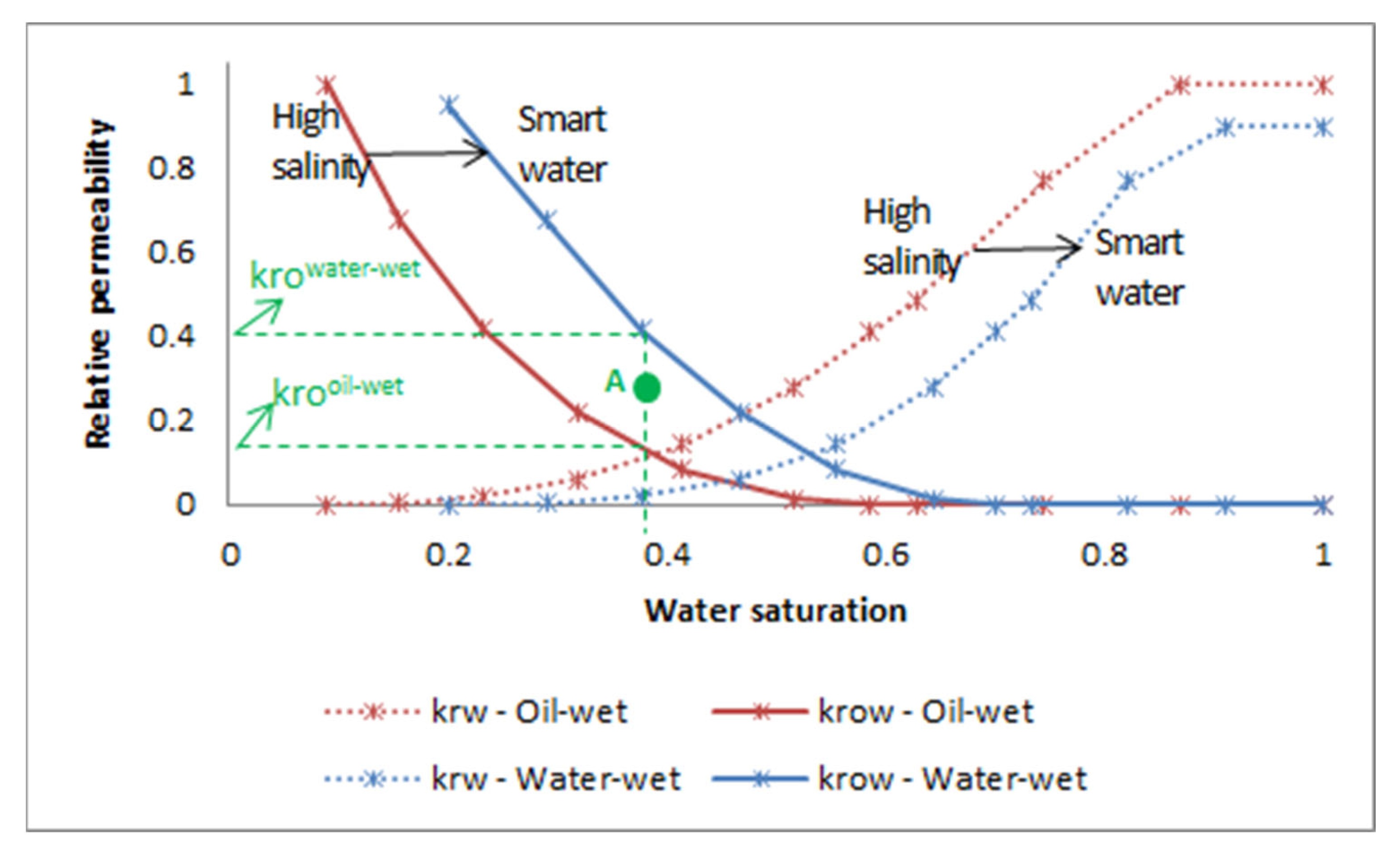
By shifting the relative permeability curves, the GEM simulator calculated the wettability alteration to a more water-wet condition. As input data required for simulation, relative permeability data, representing oil wet and water wet conditions from work developed by Dang et al. [38], were used, as shown in Figure 2. The relative permeability curves were built based on information at the endpoints, specifically on the phases’ irreducible and critical saturation conditions. The endpoints of the water–oil relative permeability curves change, which is associated with the wettability alteration due to the smart water injection, is also shown in Figure 2. Each curve represents an extreme permeability value associated with the wettability condition: maximum relative oil permeability for water-wet and minimum relative oil permeability for the oil-wet state. The reverse was for relative water permeability of water: minimum permeability for water-wet and maximum permeability for the oil-wet state. In this way, if the concentration of the interpolant ion in a specific grid block during the simulation assumes an intermediate value to these extreme values represented for set curves, an interpolation is performed to estimate the relative permeability of the water and oil phases, using Equation (1):
k r i i n t e r p o l a t e d = w · k r i o i l w e t + ( 1 w ) · k r i w a t e r w e t
where: i is the phase water or oil, kri interpolated is the new value of relative permeability calculated by the interpolation for that phase i; kri oil-wet is the value of relative permeability for the phase i, associated with the oil-wet curve presented in Figure 2, kri water-wet is the value of relative permeability for the phase i associated with the water-wet curve shown in Figure 2, and w is an interpolation factor computed by the Equation (2), considering a component aqueous phase concentration as interpolation criterion. Figure 2 shows how the krooil-wet and krowater-wet values are identified, to calculate the kro interpolated value at point A, whose water saturation is 0.38 and that of oil saturation is 1 − Sw = 0.62.
w = ( x j b l o c k , t x j o i l w e t x j w a t e r w e t x j o i l w e t ) n
where: x is a component aqueous phase concentration, j is related to the interpolant ion used in the specific simulation (Mg2+ or SO42−), n is a curvature exponent for the interpolation (defaulted to 1), xjblock,t is the ion interpolant concentration calculated in a specific grid block and determined time t during the simulation, xjwater-wet is the ion interpolant concentration associated with the water-wet curve set, and xjoil-wet is the ion interpolant concentration associated with the oil-wet curve set.
This study used the interpolation criterion based on the ion concentration in the aqueous phase, specifically SO42− and Mg2+. Magnesium cation was selected instead of calcium due to the high temperature of the simulated scenario, considering that in this condition, Mg2+ has a more critical role than Ca2+ [20,23,24,25]. In this way, 24 different scenarios were investigated, as outlined in Table 4, considering both the variation of the smart water and the interpolation ion.
For the curve corresponding to the oil-wet condition in Figure 2, the concentrations of synthetic seawater were xjoil-wet equal to 24 ppm of SO42− (when SO42− is the interpolant ion) and xjoil-wet equal to 170 ppm of Mg2+ (when Mg2+ is the interpolant ion). And for the curve corresponding to the water-wet condition, concentrations of xjwater-wet equal to 0.8 ppm of SO42− (when SO42− is the interpolant ion) and xjwater-wet equal to 5.7 ppm of Mg2+ (when Mg2+ is the interpolant ion) were used.
Gas–liquid relative permeability data are shown in Figure S1 of the Supplementary Materials.

2.3. Smart Water Mechanisms

An exhaustive discussion is presented in the literature about the role of divalent ions and salinity reduction of injected water in wettability alteration. As highlighted in Figure 3a, carbonate rocks tend to have a positively charged surface, which keeps the negative polar components of the oil adhered and results in initial oil wet behavior that is unfavorable for recovery. Formation water, which has a high concentration of salts, typically has low sulfate content. Through smart water injection, there is a reduction in the total ion concentration in the aqueous phase, which facilitates the access of potential ions to the rock surface. Sulfate is one of these potential ions that must be present in the injected water. Due to its negative charge, it tends to approach the positively charged carbonate and weaken the oil’s interactions with the rock in the ion exchange process represented in Figure 3b. Sequentially, other chemical interactions occur between the Ca2+ and Mg2+ ions and the rock and oil as well as between these ions and the sulfate, exemplified in Figure 3c. In summary, what has been widely accepted is that such interactions and pH increases lead to changes in rock wettability and enhanced recovery [29]. When simulating smart water injection, all these interactions that contribute to the oil recovery mechanism are well represented. As in the simulations, the relative permeability curves fully explain the wettability alteration. The uncertainties arising from the interpolation of these curves can affect this recovery’s qualitative and quantitative description. Refining the simulation models, ensuring a good agreement with these phenomena, allows more reliable estimates to support proposals for implementation projects by oil companies.

3. Results and Discussion

3.1. Oil Behavior Model

PVT experimental data from Sequeira [35] were used for tuning the EOS. This procedure was necessary before the core flooding simulations. The results of the differential liberation experiment data, regressed using the Winprop simulator developed by CMG, are presented in Table S2 and Figures S1–S6 of the Supplementary Materials.

3.2. Core Flooding Simulations

The oil recovery factors obtained for all 24 simulated scenarios are shown in Figure 4. Initially, a quantitative discussion of the results is carried out based on an overview analysis of the influence of salinity reduction and the presence of potential ions on the recovery factor. This work is divided into two sections to present better the results of the core flooding simulations for the different proposed scenarios. The first section discusses the effects of monovalent and divalent cations concentration on oil recovery, as illustrated in Figure 4. The presence of potential ions (Mg2+ and SO42−) is considered responsible for the wettability alteration, as shown in Figure 3. The second section deals with brine salinity reduction and its effects on SWF. The brine dilution has a more direct relationship with shifting the relative permeability curves intersection to the right, as shown in Figure 2, which physically indicates the wettability alteration from the oil-wet to water-wet state. A comparative discussion of the results obtained depending on the interpolant ion used is presented for both sections. The simulation results and experimental studies at the core scale allow oil recovery estimates, as discussed by Kadeethum et al. (2017) [33]. However, it is imperative to highlight that the extrapolation of these results to the field scale must consider the existing heterogeneity in the reservoirs and the simplifications for carrying out studies on a smaller scale.

3.2.1. Monovalent Versus Divalent Cations Effluent Concentration: Influence on Oil Recovery Factor, According to SWF Mechanisms

Oil recovery results for synthetic seawater (STD) flooding compared to those for brines rich in monovalent cations (MV) and brines rich in divalent cations, presented in Figure 4, lead to two distinct trends:
  • When sulfate is the interpolant ion, the estimated oil recovery follows a decreasing order: brines rich in divalent cations (DV) > synthetic seawater (STD) > brines rich in monovalent cations (MV). This trend is reversed as long as brine dilutions are evaluated. The recovery is the same for the injection of brine rich in monovalent ions and seawater brine, as seen in the condition of maximum dilution investigated (30x).
  • When magnesium is the interpolant ion, the estimated oil recovery occurs in the following order: brines rich in monovalent cations (MV) > synthetic seawater (STD) > brines rich in divalent cations (DV). The recovery factor estimate for injections of synthetic seawater (STD) becomes closer to the results for brines rich in monovalent ions (MV) as the dilution factor increases. For all cases, the recoveries with brines rich in divalent cations (DV) are lower than in the other scenarios.
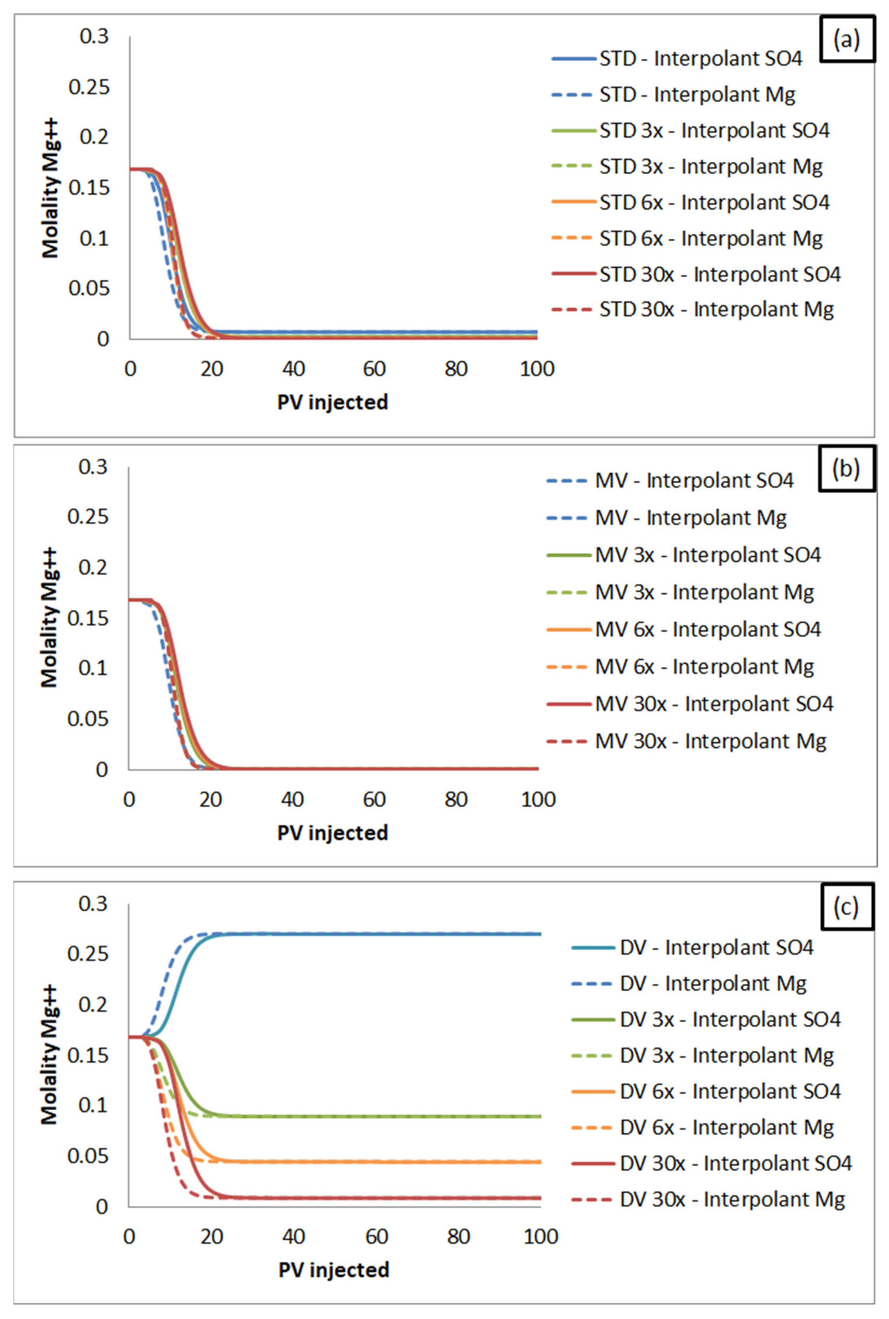
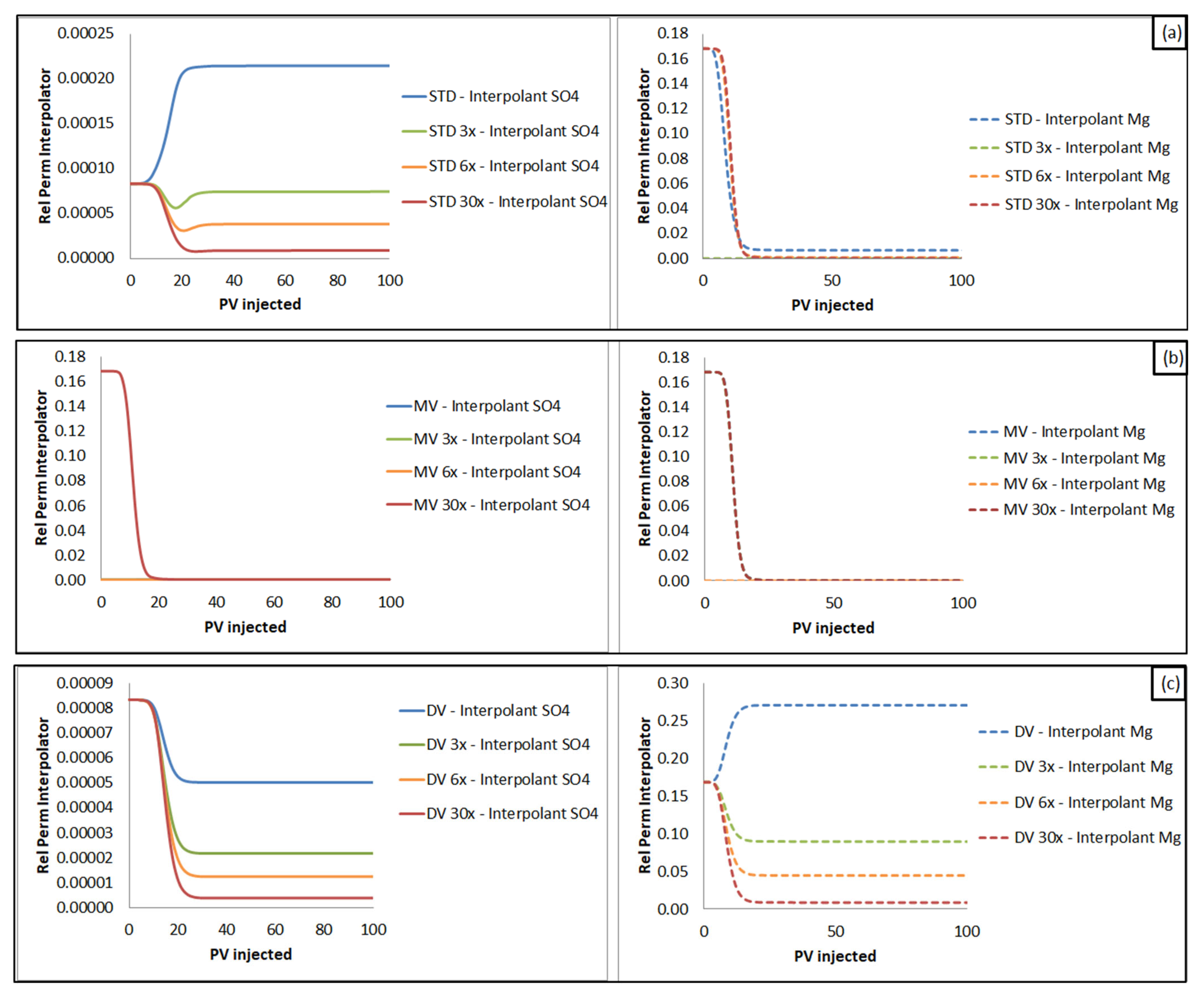
The reason for these variations and the recovery mechanisms involved can be analyzed through the concentration curves of the interpolating ions in the effluent: SO42− shown in Figure 5 and Mg2+ in Figure 6, and the interpolation factor w (Equation (2)) variation of the relative permeability curves presented in Figure 7.
SO42− is a component of all injected brines investigated in this work, as shown in Table 3. Therefore, the variation of this anion concentration was analyzed in the porous medium between the water-wet condition (sulfate molality = 0.000008) and the oil-wet condition (sulfate molality = 0.00025), as represented by point A in the Figure 2. The concentration of SO42− in the formation water (initial core condition: sulfate molality = 0.00083) is between these two limit values. The interpolation of the relative permeability curves was performed in this concentration range. It is possible to confirm that the curves with lower sulfate concentration, shown in Figure 5, correspond to the scenarios that showed higher oil recovery factors in Figure 4, since the value of the interpolant tends to approach the curve of the water-wet state.
However, suppose Mg2+ is the interpolant ion. In the scenarios with brines rich in monovalent cations, whose magnesium concentration is zero, this ion concentration is considerably reduced, as seen in Figure 6b. Mg2+ concentration assumes values near that set for water-wet conditions because magnesium concentration is diluted in the formation water. So, the results are always higher, as they are closer to the most favorable wettability condition for oil recovery. Similar recovery results are also obtained with synthetic seawater and its dilutions because when they are injected, the magnesium concentration is reduced by dilution (Figure 6a), leading to more proximity to the water-wet state (in terms of relative permeability curves). On the other hand, in scenarios with brines rich in divalent cations, due to the absence of Na+ and K+ ions, the magnesium concentration in the medium assumes higher values (Figure 6c) when compared to synthetic seawater. Therefore, the relative permeability for these scenarios is closer to the curve of oil-wet conditions, which leads to lower oil recovery.
Due to the inconsistencies mentioned above, sulfate is the most appropriate ion to be used as an interpolant for the core flooding tests simulated in this work. This anion allows comparison of the effects of divalent and monovalent cations on oil recovery. Based on this conclusion and considering only the results for sulfate as an interpolant, the beneficial effect of increasing Ca2+ and Mg2+ concentration is evident. Another important observation of these results is that even very low sulfate concentrations, as observed for all simulated injected brines, are highly relevant in the smart water injection process.
Considering Equation 1, the higher the interpolation factor (w), the closer will be the relative permeability to that observed for the oil-wet condition, which results in a lower oil recovery factor. In the oil-wet state, the relative permeability to oil is lower than in the water-wet condition, and, on the other hand, the relative permeability to water is greater than in the water-wet condition. That is, water flow is favored, and oil flow is worse when the curve in Figure 2 is shifted to the left, more oil-wet. For this reason, Figure 7 shows the values of the interpolation factor given by the relative permeability curves. In these cases, w more positive values led to lower recovery estimates, as shown in Figure 4. As the selected interpolant is the concentration of magnesium and sulfate ions in the aqueous phase, the values of the interpolation factor in Figure 7 are directly related to the results shown in Figure 5 and Figure 6.

3.2.2. Dilution Effects: Influence on Oil Recovery Factor, According to SWF Mechanisms

When comparing the results of oil recovery (Figure 4) of concentrated brines (STD, MV and DV) with those of brines with different levels of dilution (3×, 6× and 30×), the main observation was: the more diluted the injected brine, the greater the recovery factor. This recovery improvement with salinity reduction occurred for simulations with synthetic seawater with less abrupt variation in interpolating ion and potential ion concentrations. As seen in Figure 5 and Figure 6, for more dilute injection brines, the interpolant ion concentration is lower, so during the simulation, the relative permeability values are estimated close to those of the relative permeability curve corresponding to the water-wet state (Figure 2), which favors oil recovery. This result reinforces the importance of careful characterization of the relative permeability curves.
These preliminary analyses consider the oil recovery factor estimates as a result of variations in salinity and composition of the injected brines in the range of relative permeability involved. The following discussions, in turn, analyze the pH, effluent concentration and ion exchange equivalent fractions, allowing us to relate the performance obtained with the mechanism involved and represented by the simulator.

3.2.3. Smart Water Flooding Mechanisms Simulation

Additional results were evaluated to ensure the process was captured adequately during the simulations for the different interpolants. From Figure 5 and Figure 6, it is possible to analyze one of the oil recovery mechanisms during the simulation of smart water injection. It was considered that ion exchanges, involving mainly divalent ions, promote a wettability alteration, which, in turn, is represented in the simulations through interpolating the water-oil relative permeability curves. Initially, the aqueous phase is characterized by the composition of the formation water itself. With the injection of the brine of different concentrations and lower total concentrations of salts, two processes coincide and lead to the variation of the interpolant ion concentrations: the dilution and the variation due to ion exchanges. Magnesium has a high concentration in the formation water; with consumption due to exchanges and dilution, its concentration reduces in the effluent. The distinct behavior occurs when the divalent ion-rich brine, which has a significant magnesium concentration, is evaluated so that different levels of Mg2+ molality can be seen in the effluent (Figure 6c). Particularly for a divalent ion-rich brine with 30,000 ppm of total salt concentration (DV), an Mg2+ concentration increase is observed. It occurs because the ion exchange losses cannot overcome the continuous injection of brine with a magnesium concentration higher than the formation water. When evaluating the variation of sulfate concentration (Figure 5), the same aspects must be considered. But in this case, the sulfate concentration in the formation water is lower than that of the concentrated brines (STD, MV and DV) and equal to 3× diluted brines (STD 3×, MV 3× and DV 3×). For this sulfate concetration, it is possible to identify an initial concentration reduction as the sum of the dilution and consumption by ion exchange, followed by a concentration increase corresponding to the water breakthrough, i.e., the effluent concentration corresponding to that of the injected water.
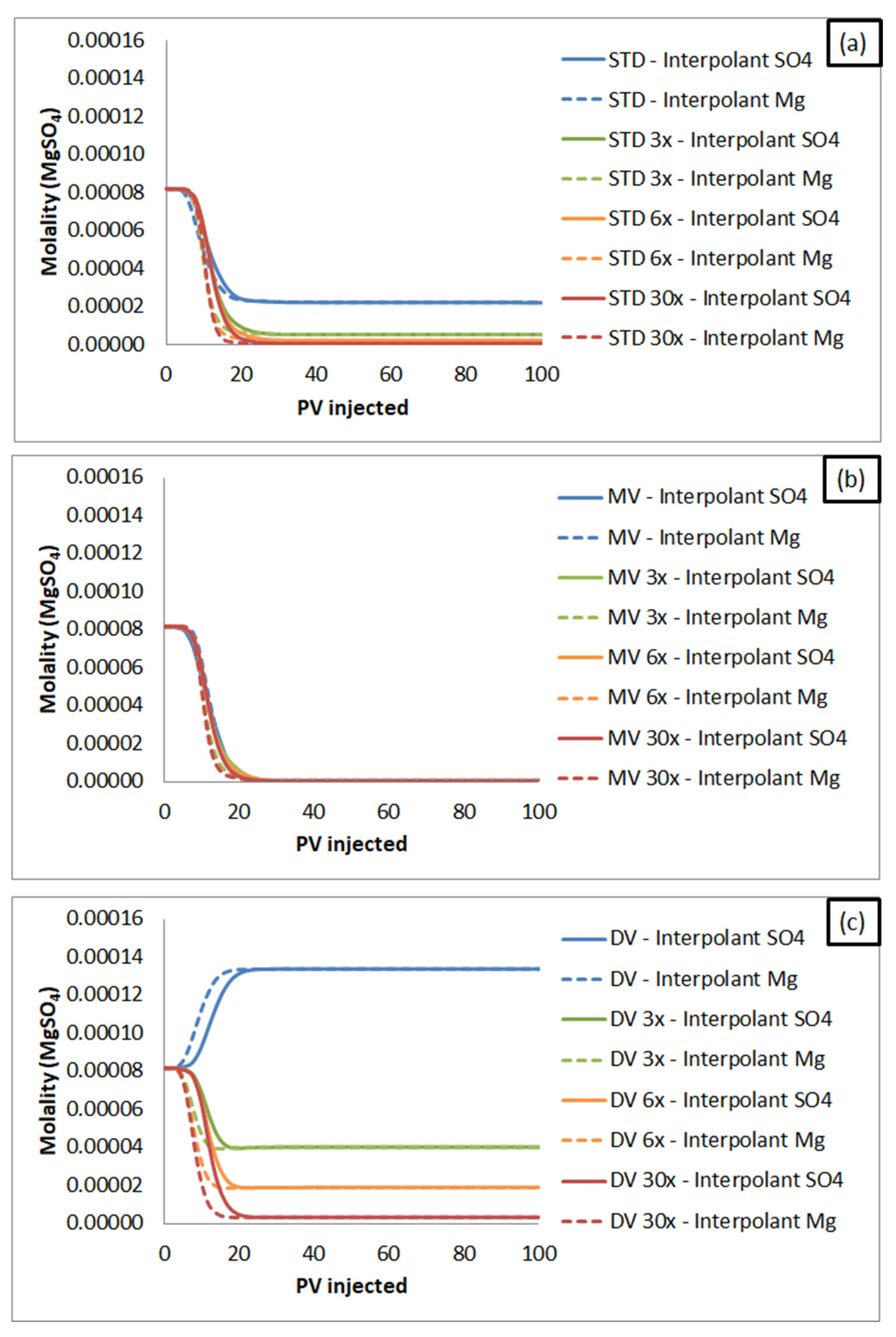
Regarding the divalent ion-rich brine (Figure 5c), sulfate concentration in effluent reduces for all dilution scenarios, even for brine with SO42− concentration higher than that of formation, for which opposite behavior was expected. In this context, it is essential to highlight that mineral precipitation reactions between Ca2+ and Mg2+ and sulfate also occur, as indicated in reactions S3 and S4 listed in the Supplementary Materials. The graph in Figure 8 shows the magnesium sulfate precipitation trend in the effluent. As seen in Figure 8c, there is a MgSO4 concentration increase when concentrated DV brine is injected. The discrepancy concerning the trends discussed above may be due to MgSO4 precipitation caused by the high concentration of Mg2+ and SO42−. It favors the displacement of the reaction MgSO4 ↔ SO42− + Mg2+ to the left side, with additional consumption of sulfate and magnesium ions.
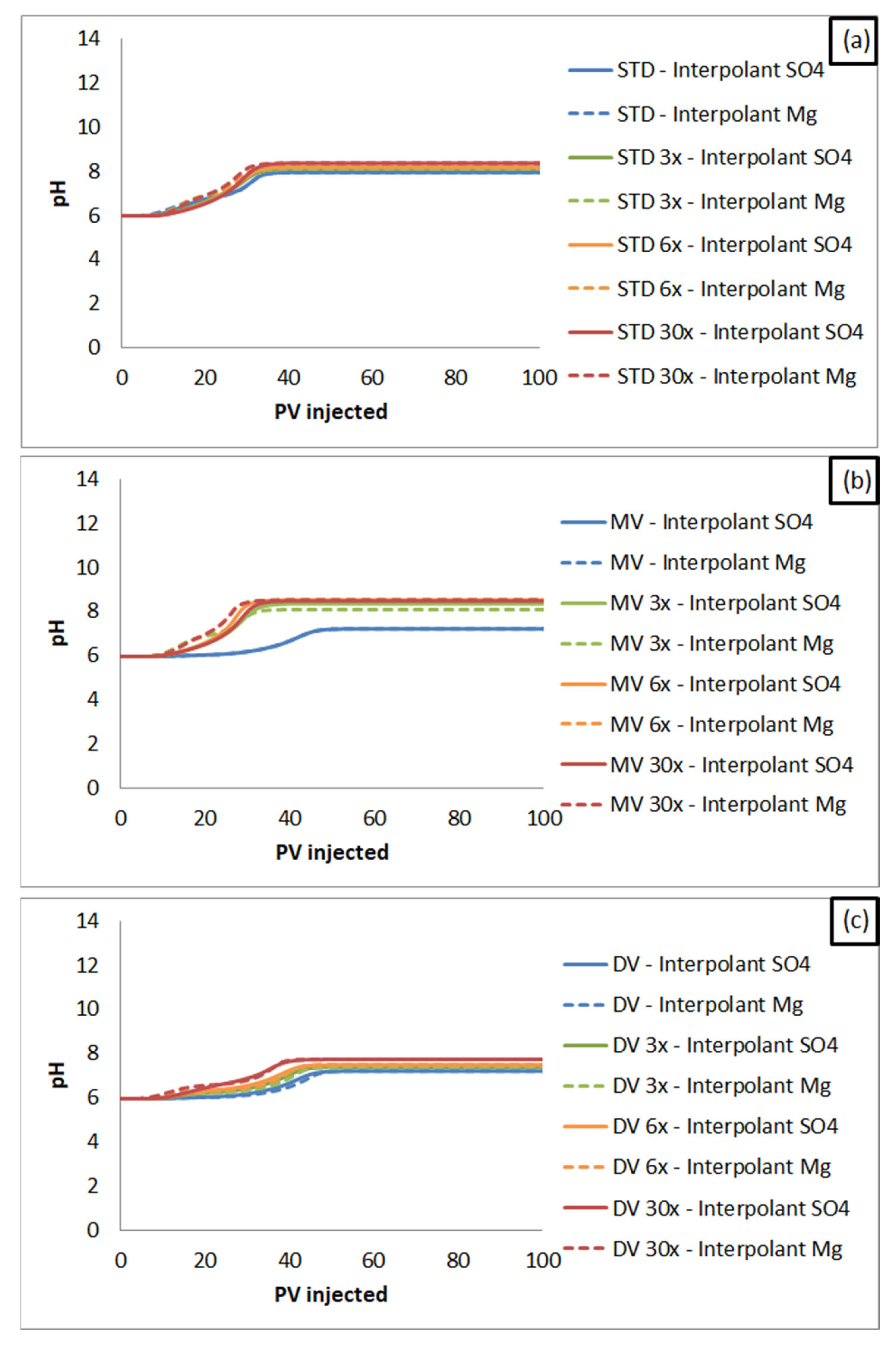
Concerning another physicochemical alteration in the porous medium, Figure 9 shows the pH variation in the effluent as a consequence of the processes that are taking place in the core during smart water injection. Figure 9 shows an increase in the pH of the effluent during the injection for all simulated scenarios, which indicates that the recovery process was adequately described. This increase is also a critical alteration during smart water flooding, observed in most experimental studies. Some authors consider pH one of the main factors leading to wettability alteration [39]. Calcite, one of the main minerals observed in carbonate reservoirs, tends to have a more negative surface charge with pH increase, weakening oil’s interaction with rock [12]. This observation was identified mainly based on experimental analyses of zeta potential as a function of pH. But, authors such as Mohammadkhani, Shahverdi and Esfahany (2018) [40] have mentioned that the pH increase is associated with mineral dissolution reactions and cation release but have reinforced that it is not the primary recovery mechanism, mainly when SWF is applied in carbonates.
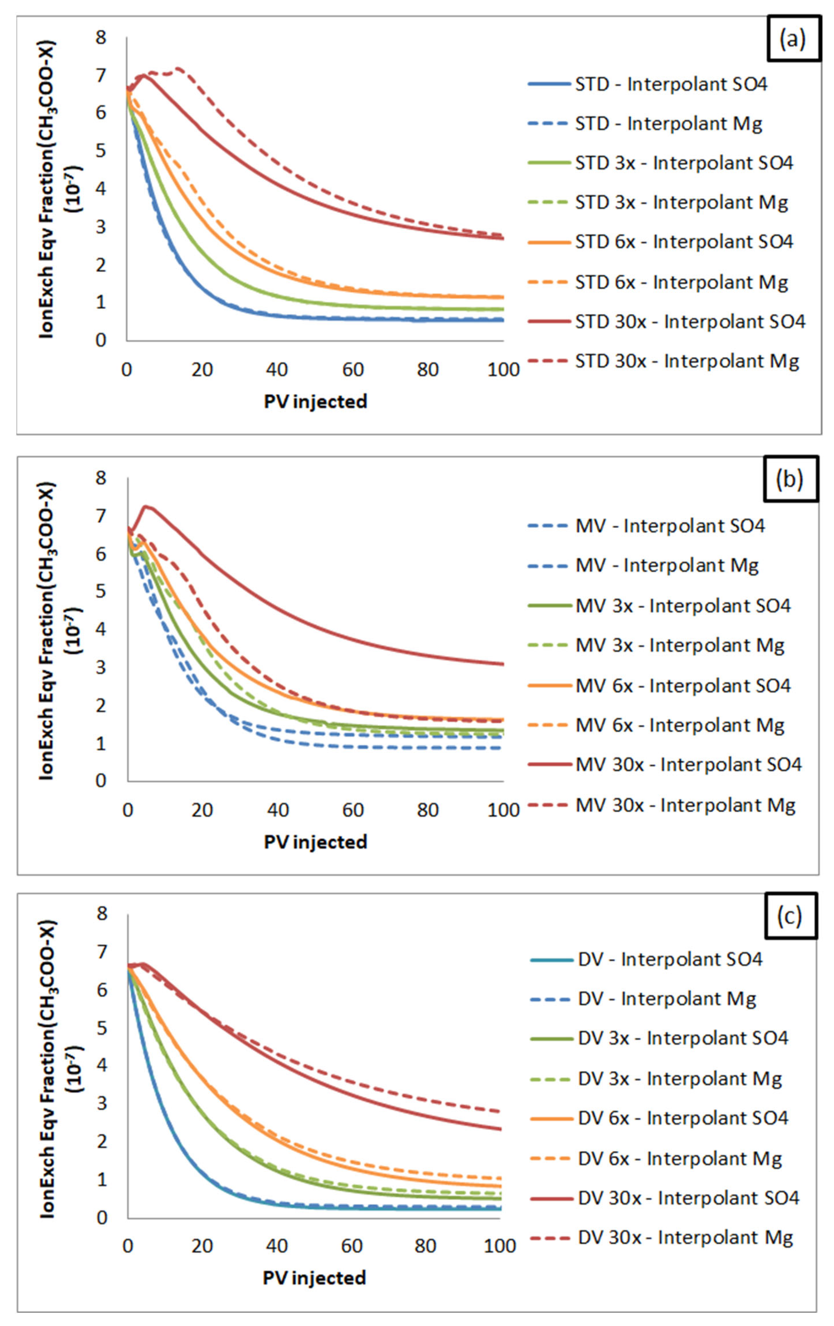
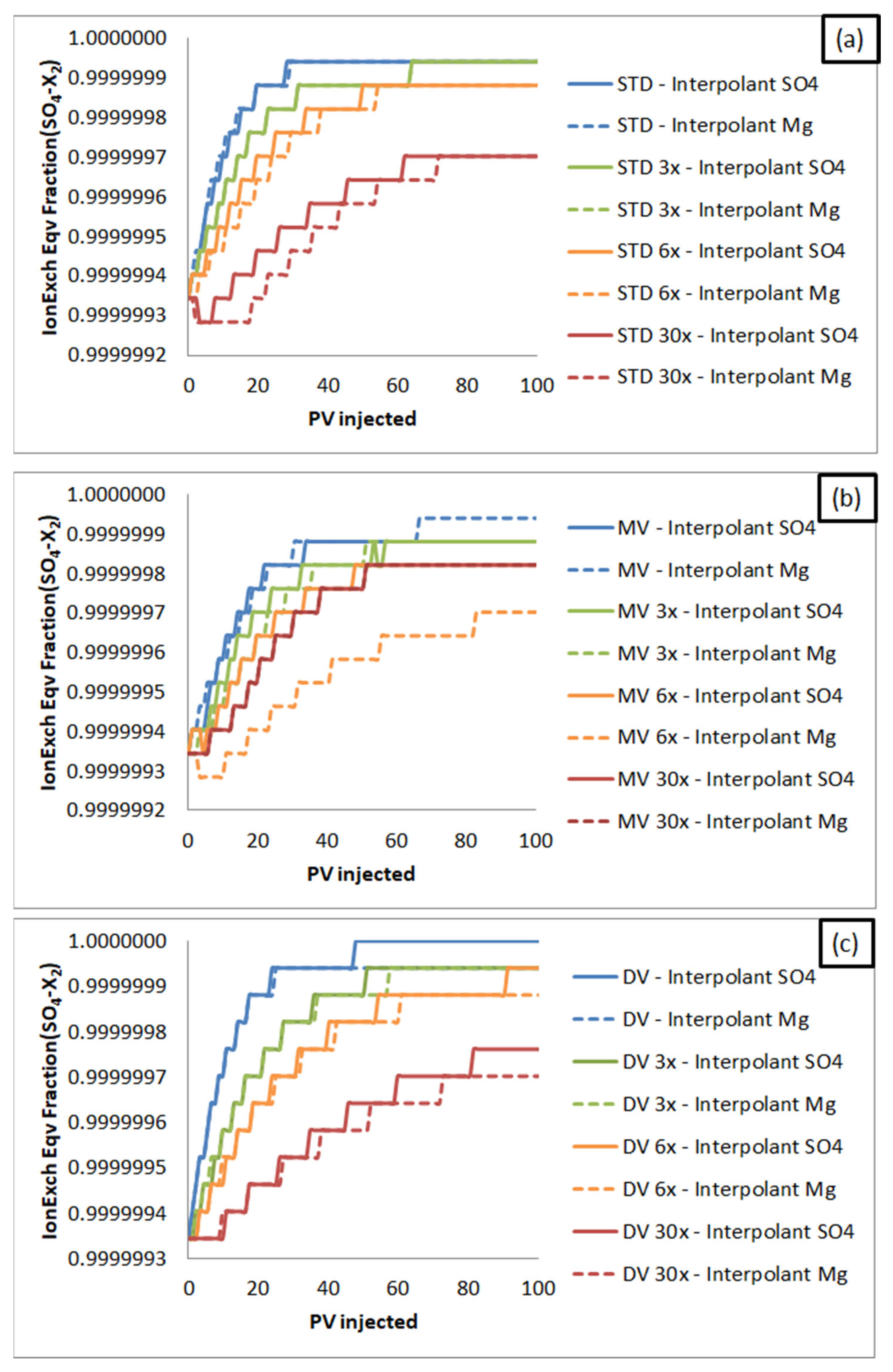
The evolution of the ion exchange equivalent fractions CH3COO-X and SO4-X2, shown in Figure 10 and Figure 11 respectively, are also important parameters to be examined. The SO42− ions adsorb on the minerals during SWF, as schematized in Figure 3, so the SO4-X2 equivalent fraction increases. On the other hand, the oil components, represented by CH3COO, are released from the rock. For this reason, the CH3COO-X equivalent fraction decreases. The monitoring of the CH3COO-X equivalent fraction, shown in Figure 10, represents the inverse of the recovery factor since the smaller the oil fraction still adhered to the rock, the greater the amount of oil that was produced. Therefore, this fraction indicates, from a complementary point of view, how the simulator evaluates the recovery mechanism. Analogously, the SO4-X2 equivalent fraction represents the mechanism precursor, initiating the ion exchange, as shown in Figure 3.

4. Conclusions

The wettability alteration is the most accepted effect to explain improved recovery through smart water injection. In simulators, this phenomenon is represented through the shifting of water–oil relative permeability curves. This paper provides a detailed simulation study investigating smart water flooding in a carbonate system. The effects of water salinity and ion composition on oil recovery are described. The primary purpose was to evaluate the impact that the selection of different interpolants has on the representation of mechanisms related to SWF and the oil recovery estimates. In the literature, the interpolant is typically used only for historic matching, and no studies have been observed that deal with their use to assess mechanisms. In this work, Mg2+ and SO42− concentrations in the aqueous phase were used as interpolant ions of relative permeability curves. The simulation results demonstrated the significant influence of the interpolant on oil recovery estimates. For each interpolant, RF also changes significantly as a function of salinity and composition. The greater the dilution, the smaller the influence of the interpolant and brine composition on the recovery estimates. When considering SO42− as an interpolant, the trend is that the divalent rich brine (DV) has a higher recovery factor. In contrast, when Mg2+ is the interpolant, DV tends to have a lower recovery. Both interpolants have reproduced the pH increase and ion exchange mechanisms associated with carbonate wettability alteration well. This behavior has been observed through geochemical analysis from effluent composition in the scenarios studied. Results based on the alteration of carbonate wettability also support the beneficial effect of divalent ions and salinity reduction on oil recovery. Future works will include the experimental validation of the observed results.

Supplementary Materials

The following supporting information can be downloaded at: https://www.mdpi.com/article/10.3390/en16010446/s1, Figure S1: Gas-Oil relative permeability curve; Figure S2: Data regression of differential liberation experiment—Gas-oil ratio; Figure S3: Data regression of differential liberation experiment—Oil specific gravity; Figure S4: Data regression of differential liberation experiment—Gas specific gravity; Figure S5: Data regression of differential liberation experiment—Oil viscosity; Figure S6: Data regression of constant composition expansion experiment—Oil density; Table S1: Modeling of phase properties in the GEM simulator; Table S2: Average deviation of the properties estimated by the model after regression of the PVT data. References [41,42,43,44] have been cited in the supplementary material.

Author Contributions

L.d.S.B.: Conceptualization, Methodology, Investigation, Writing—original draft preparation, Writing—review and editing; I.E.d.S.L.: Conceptualization, Methodology, Investigation, Writing—original draft preparation, Writing—review and editing; G.M.N.C.: Conceptualization, Methodology, Investigation, Writing—original draft preparation, Writing—review and editing, Supervision, and Project administration; S.A.B.V.d.M.: Conceptualization, Writing—review and editing, Supervision, Project administration, and Funding acquisition. All authors have read and agreed to the published version of the manuscript.

Funding

This research was funded by Petrogal Brasil S.A., grant number 20623-5.

Data Availability Statement

Not applicable.

Acknowledgments

The authors acknowledge the Agência Nacional de Petróleo, Gás Natural e Biocombustíveis (ANP) and the Petrogal Brasil S.A., related to the grant from the R&D rule, as well as the CMG’s Engineer Juan Mateo.

Conflicts of Interest

The authors declare no conflict of interest.

References

  1. Rahimi, A.; Honarvar, B.; Safari, M. The Role of Salinity and Aging Time on Carbonate Reservoir in Low Salinity Seawater and Smart Seawater Flooding. J. Pet. Sci. Eng. 2020, 187, 106739. [Google Scholar] [CrossRef]
  2. Sohal, M.A.; Thyne, G.; Søgaard, E.G. Review of Recovery Mechanisms of Ionically Modified Waterflood in Carbonate Reservoirs. Energy Fuels 2016, 30, 1904–1914. [Google Scholar] [CrossRef]
  3. Egbe, D.I.O.; Jahanbani Ghahfarokhi, A.; Nait Amar, M.; Torsæter, O. Application of Low-Salinity Waterflooding in Carbonate Cores: A Geochemical Modeling Study. Nat. Resour. Res. 2021, 30, 519–542. [Google Scholar] [CrossRef]
  4. Xu, Z.X.; Li, S.Y.; Li, B.F.; Chen, D.Q.; Liu, Z.Y.; Li, Z.M. A Review of Development Methods and EOR Technologies for Carbonate Reservoirs. Pet. Sci. 2020, 17, 990–1013. [Google Scholar] [CrossRef]
  5. Al-Shalabi, E.W.; Sepehrnoori, K.; Pope, G. Geochemical Interpretation of Low-Salinity-Water Injection in Carbonate Oil Reservoirs. SPE J. 2015, 20, 1212–1226. [Google Scholar] [CrossRef]
  6. Zallaghi, M.; Khaz’ali, A.R. Experimental and Modeling Study of Enhanced Oil Recovery from Carbonate Reservoirs with Smart Water and Surfactant Injection. Fuel 2021, 304, 121516. [Google Scholar] [CrossRef]
  7. Lashkarbolooki, M.; Ayatollahi, S.; Riazi, M. Mechanistical Study of Effect of Ions in Smart Water Injection into Carbonate Oil Reservoir. Process. Saf. Environ. Prot. 2017, 105, 361–372. [Google Scholar] [CrossRef]
  8. Yousef, A.A.; Al-Saleh, S.; Al-Jawfi, M. New Recovery Method for Carbonate Reservoirs through Tuning the Injection Water Salinity: Smart WaterFlooding. In Proceedings of the SPE EUROPEC/EAGE Annual Conference and Exhibition, Vienna, Austria, 23–26 May 2011. [Google Scholar]
  9. Yousef, A.A.; Al-Saleh, S.; Al-Jawfi, M. Smart Waterflooding for Carbonate Reservoirs: Salinity and Role of Ions. SPE Middle East Oil Gas Show Conf. MEOS Proc. 2011, 1, 632–642. [Google Scholar] [CrossRef]
  10. Yousef, A.A.; Liu, J.; Blanchard, G.; Al-Saleh, S.; Al-Zahrani, T.; Al-Zahrani, R.; Al-Tammar, H.; Al-Mulhim, N. SmartWater Flooding: Industry’s First Field Test in Carbonate Reservoirs. In Proceedings of the SPE Annual Technical Conference and Exhibition, San Antonio, Texas, USA, 8–10 October 2012. [Google Scholar]
  11. Rassenfoss, S. Scaling Up Smart Water. J. Pet. Technol. 2016, 68, 39–41. [Google Scholar] [CrossRef]
  12. Hao, J.; Mohammadkhani, S.; Shahverdi, H.; Esfahany, M.N.; Shapiro, A. Mechanisms of Smart Waterflooding in Carbonate Oil Reservoirs—A Review. J. Pet. Sci. Eng. 2019, 179, 276–291. [Google Scholar] [CrossRef]
  13. Elgendy, A.M.S.; Porta, G.M. Impact of Reservoir Geochemistry on Low Salinity Waterflooding: Global Sensitivity Analysis. J. Pet. Sci. Eng. 2021, 207, 109056. [Google Scholar] [CrossRef]
  14. Zhang, T.; Li, Y.; Li, C.; Sun, S. Effect of Salinity on Oil Production: Review on Low Salinity Waterflooding Mechanisms and Exploratory Study on Pipeline Scaling. Oil Gas Sci. Technol. 2020, 75, 50. [Google Scholar] [CrossRef]
  15. Mahmoudpour, M.; Pourafshary, P. Investigation of the Effect of Engineered Water/Nanofluid Hybrid Injection on Enhanced Oil Recovery Mechanisms in Carbonate Reservoirs. J. Pet. Sci. Eng. 2021, 196, 107662. [Google Scholar] [CrossRef]
  16. Al Shalabi, E.W.; Sepehrnoori, K.; Delshad, M. Mechanisms behind Low Salinity Water Injection in Carbonate Reservoirs. Fuel 2014, 121, 11–19. [Google Scholar] [CrossRef]
  17. Awolayo, A.N.; Sarma, H.K.; Nghiem, L.X. A Comprehensive Geochemical-Based Approach at Modeling and Interpreting Brine Dilution in Carbonate Reservoirs. In Proceedings of the SPE Reservoir Simulation Conference 2017, Montgomery, TX, USA, 20–22 February 2017; pp. 648–674. [Google Scholar] [CrossRef]
  18. Strand, S.; Puntervold, T. Recent Updates on Smart Water EOR in Limestone. In Proceedings of the Offshore Technology Conference Brasil, Rio de Janeiro, Brazil, 29–31 October 2019; pp. 29–31. [Google Scholar] [CrossRef]
  19. Shapoval, A.; Haryono, D.; Cao, J.L.; Rahman, S.S. Pore-Scale Investigation of the Ion-Tuned Water Effect on the Surface Properties of Limestone Reservoirs. Energy Fuels 2021, 35, 10475–10487. [Google Scholar] [CrossRef]
  20. Rezaeidoust, A.; Puntervold, T.; Strand, S.; Austad, T. Smart Water as Wettability Modifier in Carbonate and Sandstone: A Discussion of Similarities/Differences in the Chemical Mechanisms. Energy Fuels 2009, 23, 4479–4485. [Google Scholar] [CrossRef]
  21. Al-Shalabi, E.W.; Sepehrnoori, K.; Delshad, M.; Pope, G. A Novel Method to Model Low-Salinity-Water Injection in Carbonate Oil Reservoirs. SPE J. 2015, 20, 1154–1166. [Google Scholar] [CrossRef]
  22. Nande, S.B.; Patwardhan, S.D. A Review on Low Salinity Waterflooding in Carbonates: Challenges and Future Perspective. J. Pet. Explor. Prod. Technol. 2022, 12, 1037–1055. [Google Scholar] [CrossRef]
  23. Fathi, S.J.; Austad, T.; Strand, S. Water-Based Enhanced Oil Recovery (EOR) by “Smart Water” in Carbonate Reservoirs. In Proceedings of the SPE EOR Conference at Oil and Gas West Asia, Muscat, Oman, 16–18 April 2012; Volume 1, pp. 349–362. [Google Scholar] [CrossRef]
  24. Moradpour, N.; Pourafshary, P.; Zivar, D. Experimental Analysis of Hybrid Low Salinity Water Alternating Gas Injection and the Underlying Mechanisms in Carbonates. J. Pet. Sci. Eng. 2021, 202, 108562. [Google Scholar] [CrossRef]
  25. Dang, C.T.Q. Mechanistic Modeling of Low Salinity Waterflooding: Flow and Transport Model. Ph.D. Thesis, University of Calgary, Calgary, AB, Canada, 2015; p. 324. [Google Scholar] [CrossRef]
  26. Alshakhs, M.J.; BuKhamseen, N.Y.; AlGarni, S.A. Paradigm Shift in Smartwater Simulation Methods. In Proceedings of the International Petroleum Technology Conference 2020, Dhahran, Saudi Arabia, 13–15 January 2020; pp. 13–15. [Google Scholar] [CrossRef]
  27. Dang, C.; Nghiem, L.; Nguyen, N.; Chen, Z.; Nguyen, Q. Modeling and Optimization of Low Salinity Waterflood. In Proceedings of the SPE Reservoir Simulation Symposium, Houston, TX, USA, 23–25 February 2015; pp. 1–19. [Google Scholar] [CrossRef]
  28. Al-Shalabi, E.W.; Sepehrnoori, K.; Pope, G. Mysteries behind the Low Salinity Water Injection Technique. J. Pet. Eng. 2014, 2014, 304312. [Google Scholar] [CrossRef] [Green Version]
  29. Nguyen, N.; Dang, C.; Gorucu, S.E.; Nghiem, L.; Chen, Z. The Role of Fines Transport in Low Salinity Waterflooding and Hybrid Recovery Processes. Fuel 2020, 263, 116542. [Google Scholar] [CrossRef]
  30. Gorucu, S.E.; Dang, C.; Nghiem, L.; Shrivastava, V. Modeling and Optimization of Low Salinity Waterflood with Fines Transport. In Proceedings of the SPE Annual Technical Conference and Exhibition, Calgary, AB, Canada, 30 September–2 October 2019. [Google Scholar] [CrossRef]
  31. Esene, C.; Onalo, D.; Zendehboudi, S.; James, L.; Aborig, A.; Butt, S. Modeling Investigation of Low Salinity Water Injection in Sandstones and Carbonates: Effect of Na+ and SO42−. Fuel 2018, 232, 362–373. [Google Scholar] [CrossRef]
  32. Adegbite, J.O.; Al-Shalabi, E.W.; Ghosh, B. Geochemical Modeling of Engineered Water Injection Effect on Oil Recovery from Carbonate Cores. J. Pet. Sci. Eng. 2018, 170, 696–711. [Google Scholar] [CrossRef]
  33. Kadeethum, T.; Sarma, H.K.; Maini, B.B.; Jaruwattanasakul, C. Uncertainties–Extension of Smart Waterflooding from Core to Field Scale. In Proceedings of the IOR 2017—19th European Symposium on Improved Oil Recovery, Stavanger, Norway, 24–27 April 2017. [Google Scholar] [CrossRef]
  34. Moradpour, N.; Karimova, M.; Pourafshary, P.; Zivar, D. Effects of Slug Size, Soaking, and Injection Schemes on the Performance of Controlled Ions Water Flooding in Carbonates. ACS Omega 2020, 5, 18155–18167. [Google Scholar] [CrossRef]
  35. Sequeira, D.S. Compositional Effects on Gas-Oil Interfacial Tension and Miscibility at Reservoir Conditions. Master’s Thesis, Louisiana State University, Baton Rouge, LA, USA, 2006. [Google Scholar]
  36. Purswani, P.; Karpyn, Z.T. Laboratory Investigation of Chemical Mechanisms Driving Oil Recovery from Oil-Wet Carbonate Rocks. Fuel 2019, 235, 406–415. [Google Scholar] [CrossRef]
  37. Sarvestani, A.D.; Ayatollahi, S.; Bahari Moghaddam, M. Smart Water Flooding Performance in Carbonate Reservoirs: An Experimental Approach for Tertiary Oil Recovery. J. Pet. Explor. Prod. Technol. 2019, 9, 2643–2657. [Google Scholar] [CrossRef] [Green Version]
  38. Dang, C.T.Q.; Nghiem, L.X.; Chen, Z.; Nguyen, N.T.B.; Nguyen, Q.P. CO2 Low Salinity Water Alternating Gas: A New Promising Approach for Enhanced Oil Recovery. In Proceedings of the SPE Improved Oil Recovery Symposium, Tulsa, OK, USA, 12–16 April 2014; Volume 1, pp. 578–596. [Google Scholar]
  39. Sagbana, I.P.; Sarkodie, K.; Nkrumah, W.A. A Critical Review of Carbonate Reservoir Wettability Modi Fi Cation during Low Salinity Water Flooding. Petroleum 2022, in press. [Google Scholar] [CrossRef]
  40. Mohammadkhani, S.; Shahverdi, H.; Esfahany, M.N. Impact of Salinity and Connate Water on Low Salinity Water Injection in Secondary and Tertiary Stages for Enhanced Oil Recovery in Carbonate Oil Reservoirs. J. Geophys. Eng. 2018, 15, 1242–1254. [Google Scholar] [CrossRef] [Green Version]
  41. Peng, D.Y.; Robinson, D.B. A New Two-Constant Equation of State. Ind. Eng. Chem. Fundam. 1976, 15, 59–64. [Google Scholar] [CrossRef]
  42. Jossi, J.A.; Stiel, L.I.; Thodos, G. The Viscosity of Pure Substances in the Dense Gaseous and Liquid Phases. AIChE J. 1962, 8, 59–63. [Google Scholar] [CrossRef]
  43. Yoonm, P.; Thodos, G. Viscosity of Nonpolar Gaseous Mixtures at Normal Pressures. AIChE J. 1970, 16, 300–304. [Google Scholar] [CrossRef]
  44. Kestin, J.; Khalifa, H.E.; Sookiazian, H.; Wakeham, W.A. Experimental Investigation of Pressure Effect on the Viscosity of Water in the Temperature Range 10–15 °C. Ber. Bunsenges./Phys. Chem. Chem. Phys. 1978, 82, 180–188. [Google Scholar] [CrossRef]
Figure 1. Simulation grid design with Injector well and Production well.
Energies 16 00446 g001
Figure 2. Water–oil relative permeability curves available in Dang et al. [38].
Energies 16 00446 g002
Figure 3. Schematic of smart water injection mechanisms.
Energies 16 00446 g003
Figure 4. Oil recovery factor versus adopted approach for each simulation.
Energies 16 00446 g004
Figure 5. SO42− concentration in the effluent for brine injection: (a) STD; (b) MV and (c) DV.
Energies 16 00446 g005
Figure 6. Mg2+ concentration in the effluent for brine injection: (a) STD; (b) MV and (c) DV.
Energies 16 00446 g006
Figure 7. Interpolation factor variation of the relative permeability curves in the grid block {30,1,1} for brine injection: (a) STD; (b) MV and (c) DV.
Energies 16 00446 g007
Figure 8. MgSO4 concentration in the effluent for brine injection: (a) STD; (b) MV and (c) DV.
Energies 16 00446 g008
Figure 9. pH of the effluent for brine injection: (a) STD; (b) MV and (c) DV.
Energies 16 00446 g009
Figure 10. Ion Exchange Equivalent Fraction (CH3COO-X) variation in the grid block {1,1,1} for brine injection: (a) STD; (b) MV and (c) DV.
Energies 16 00446 g010
Figure 11. Ion Exchange Equivalent Fraction (SO4-X2) variation in the grid block {1,1,1} for brine injection: (a) STD; (b) MV and (c) DV.
Energies 16 00446 g011
Table 1. Connate water composition and properties at reservoir conditions.
IonNa+K+Ca2+Mg2+H+ClSO42−TDS
Concentration (ppm)54,370285019,74040700.0001139,8008220,838
Table 2. Oil composition and properties by Sequeira(2006) [35].
ComponentMolar Composition (%)ComponentMolar Composition (%)
CO20.036N20.023
CH423.736C2H60.009
C3H80.064NC40.342
iC40.117NC50.786
iC50.822C62.644
C7+71.423
Molecular weight (g/mol)164Gas-oil ratio (ft3/bbl)167Specific Gravity @15 °C0.8359
Table 3. Ionic concentration (in ppm) of the synthetic seawater and smart water evaluated in this study.
STDSTD 3xSTD 6xSTD 30xMVMV 3xMV 6xMV 30xDVDV 3xDV 6xDV 30x
Na+11,0753691.71845.8369.211,3763792.01896.0379.20.00.00.00.0
K+393131.065.513.1404134.767.313.50.00.00.00.0
Ca2+14247.323.74.70.00.00.00.052391746.3873.2174.6
Mg2+17056.728.35.70.00.00.00.065412180.31090.2218.0
Cl18,8476282.33141.2628.218,8476282.33141.2628.218,8476282.33141.2628.2
SO42−248.04.00.8248.04.00.8248.04.00.8
TDS30,65110,2175108.51021.730,65110,2175108.51021.730,65110,2175108.51021.7
Table 4. Overview of all simulated scenarios in this study.
ScenarioInjection BrineScenarioInjection BrineScenarioInjection BrineInterpolant Ion
1STD9MV17DVMg2+
21018SO42−
3STD 3x11MV 3x19DV 3xMg2+
41220SO42−
5STD 6x13MV 6x21DV 6xMg2+
61422SO42−
7STD 30x15MV 30x23DV 30xMg2+
81624SO42−
Disclaimer/Publisher’s Note: The statements, opinions and data contained in all publications are solely those of the individual author(s) and contributor(s) and not of MDPI and/or the editor(s). MDPI and/or the editor(s) disclaim responsibility for any injury to people or property resulting from any ideas, methods, instructions or products referred to in the content.