
Review of the Monitoring Applications Involved in the Underground Storage of Natural Gas and CO2


Abstract
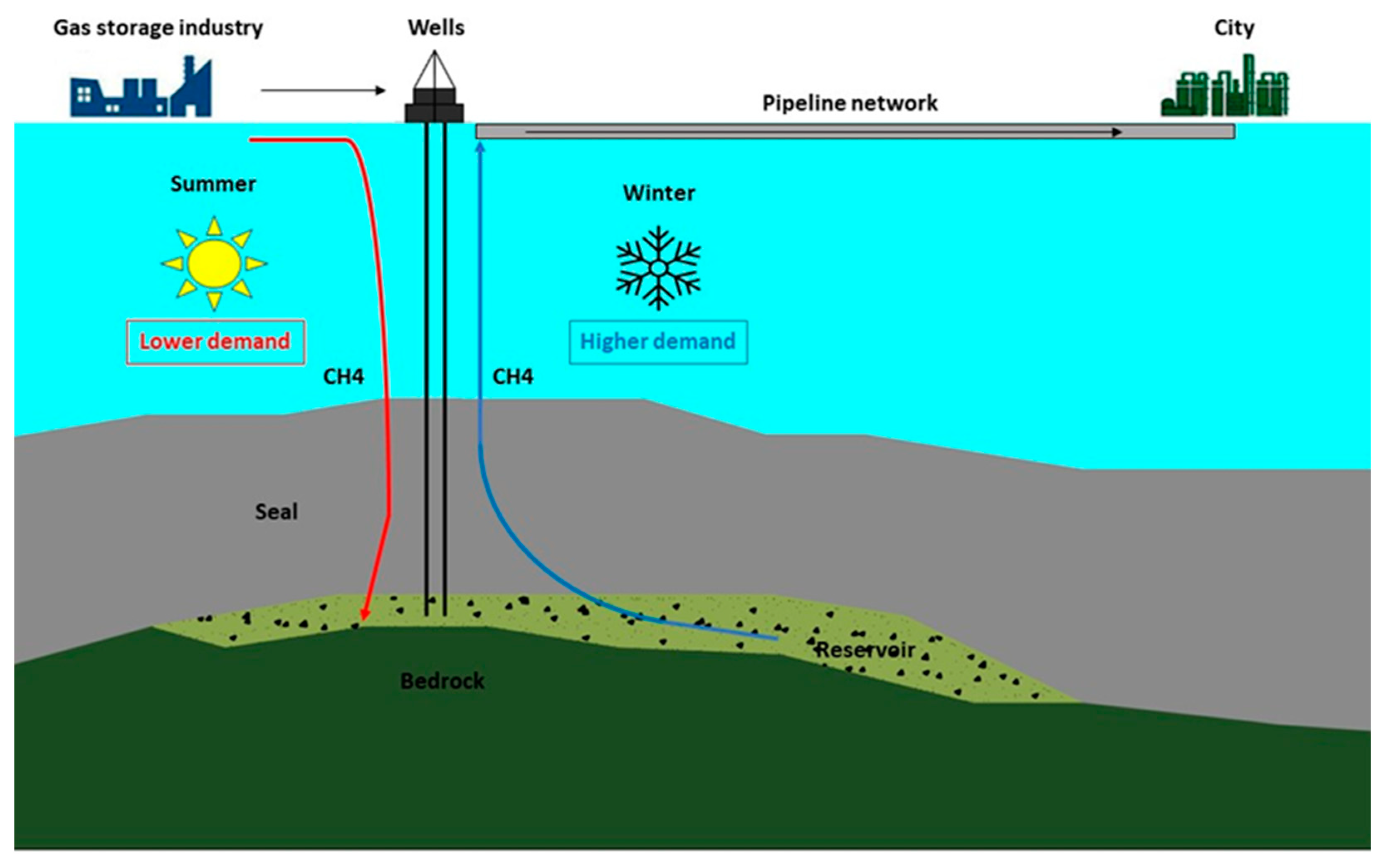
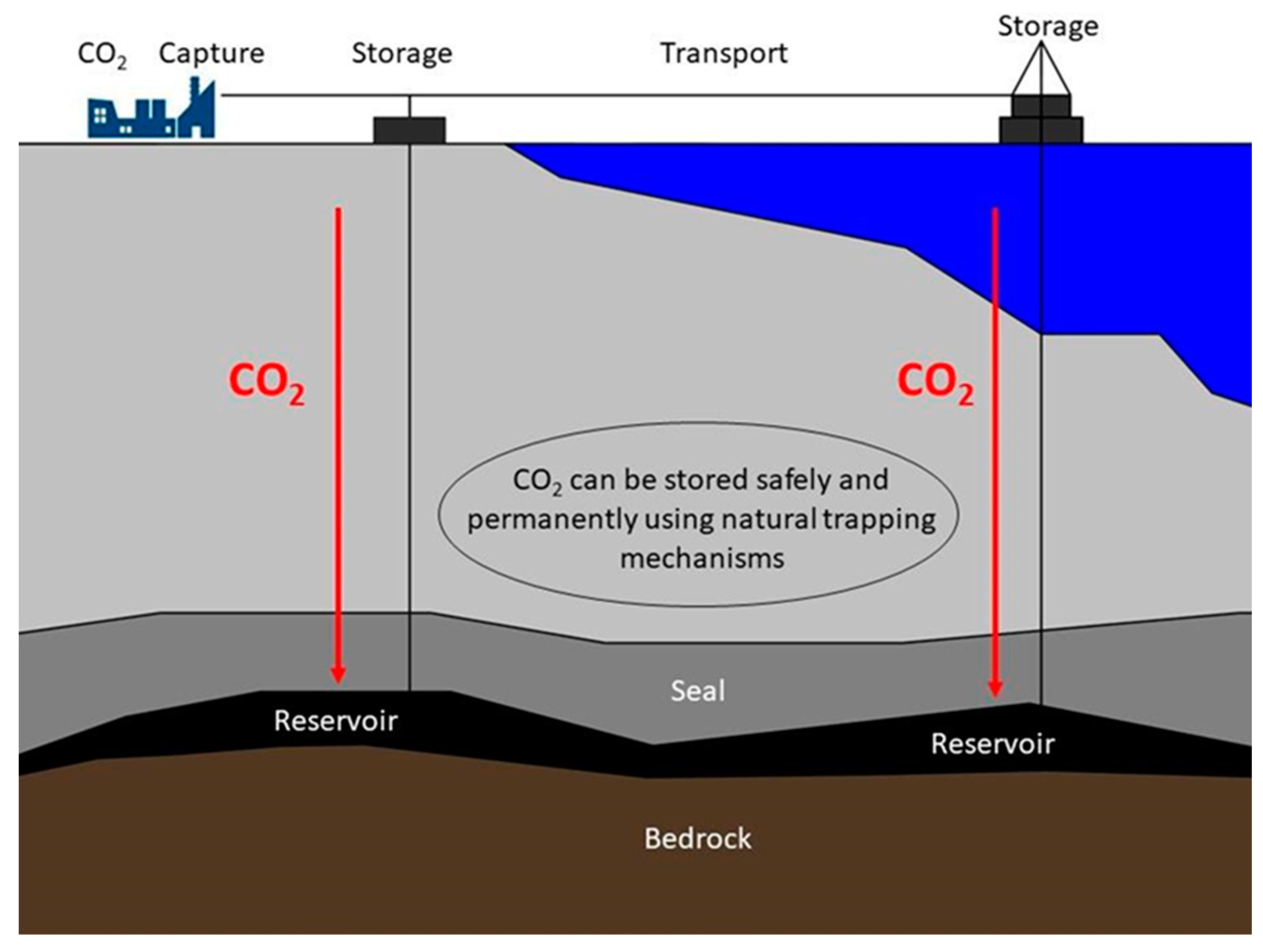
1. Introduction
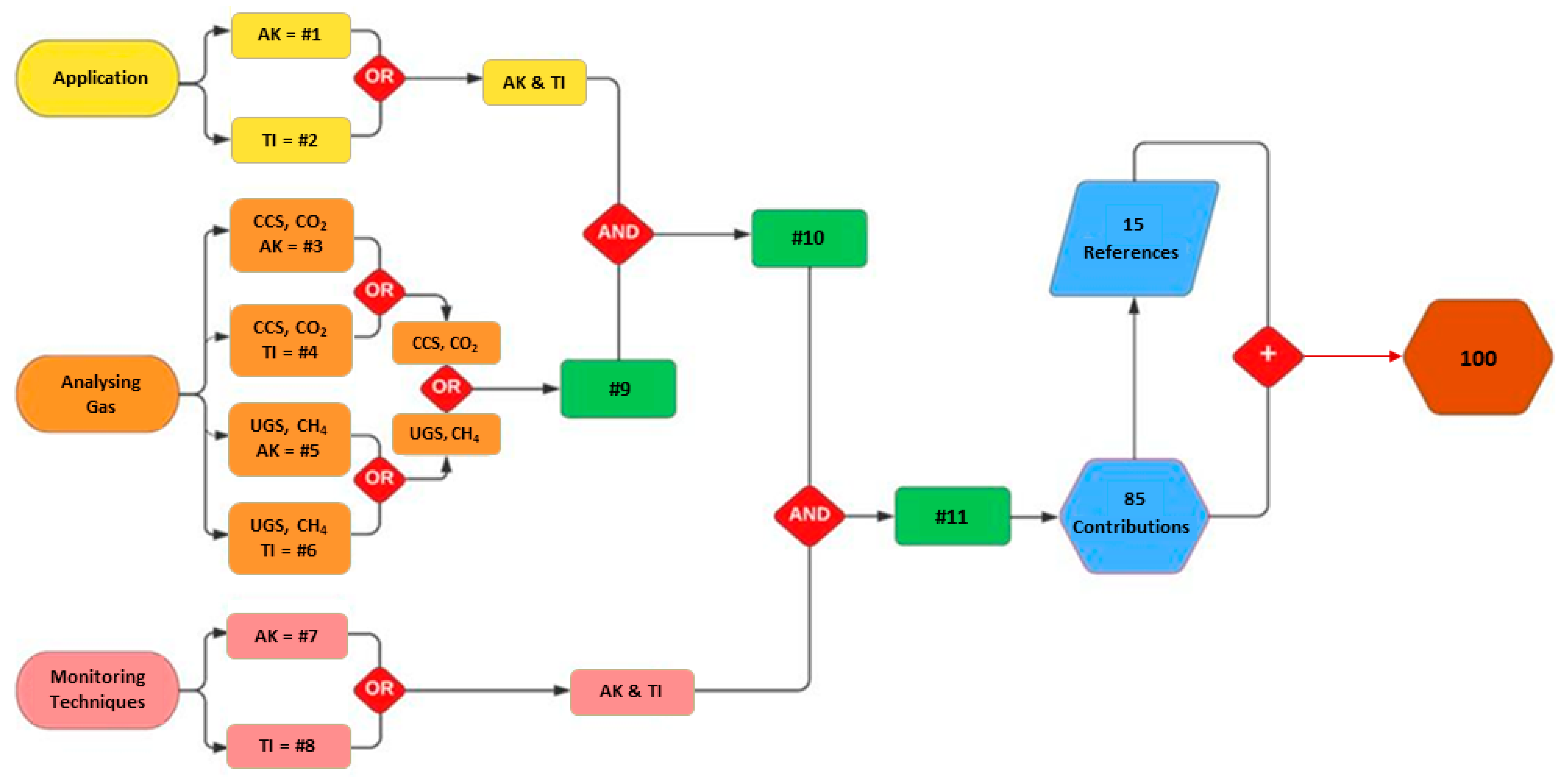
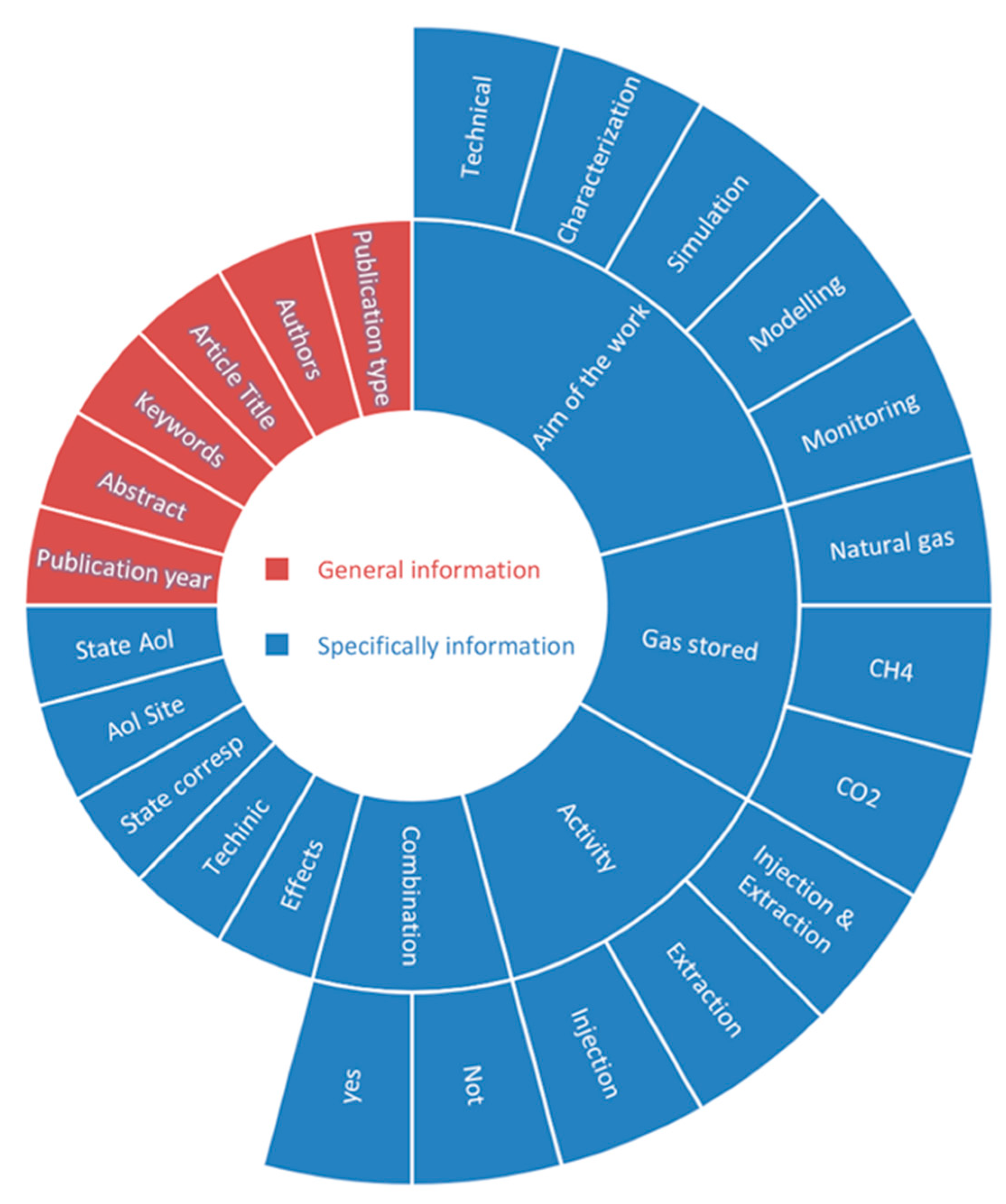
2. Data Collection
- Publication type—distinction between articles in journals (J), proceedings of conferences (C), or books (B);
- Authors;
- Article title;
- Author keywords;
- Abstract;
- Publication year;
- State Aol;
- Aol site;
- State corresponding;
- Activity—injection or extraction;
- Aim of the work—the type of research, the present work being categorized into five classes as (i) monitoring, (ii) modeling, (iii) simulation, (iv) characterization, and (v) technical;
- Gas stored;
- Investigation technique;
- Combination of more techniques—if the main monitoring technique is combined with another activity;
- Ground deformation effects.
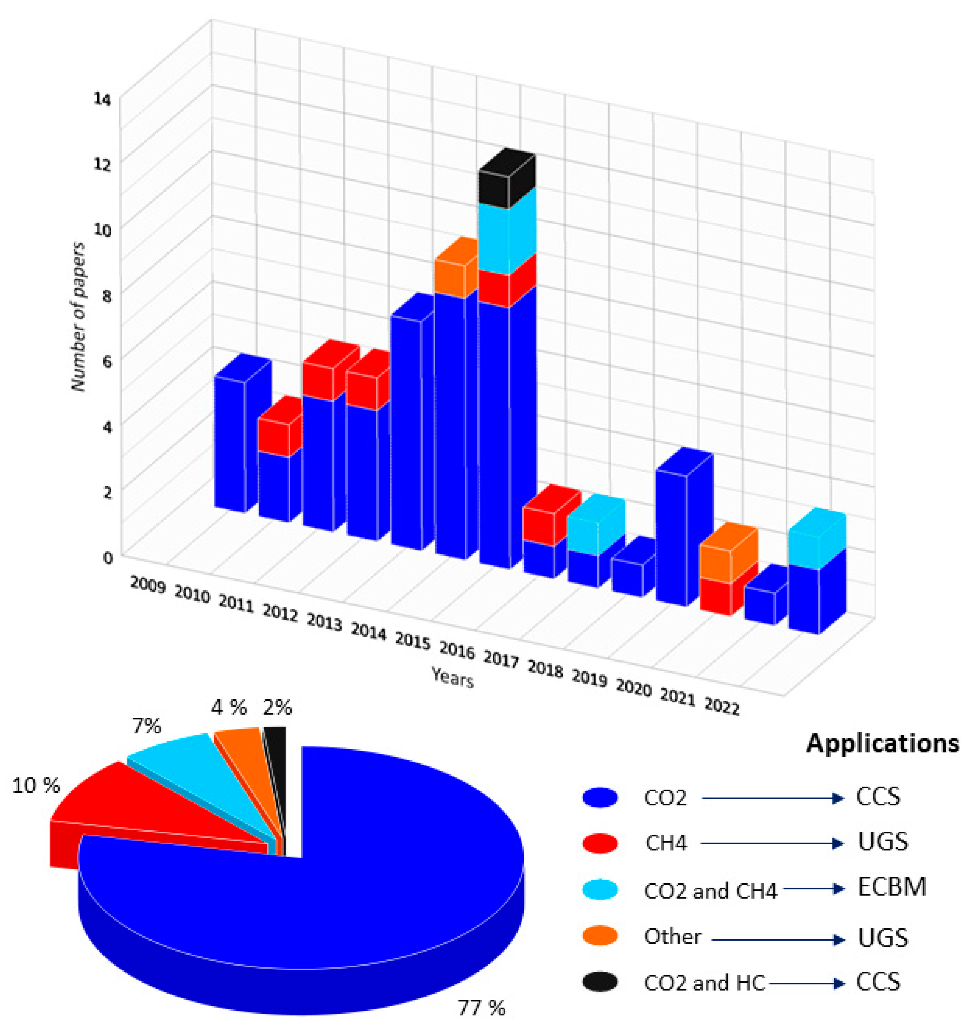
3. Temporal Evolution of the Scientific Production
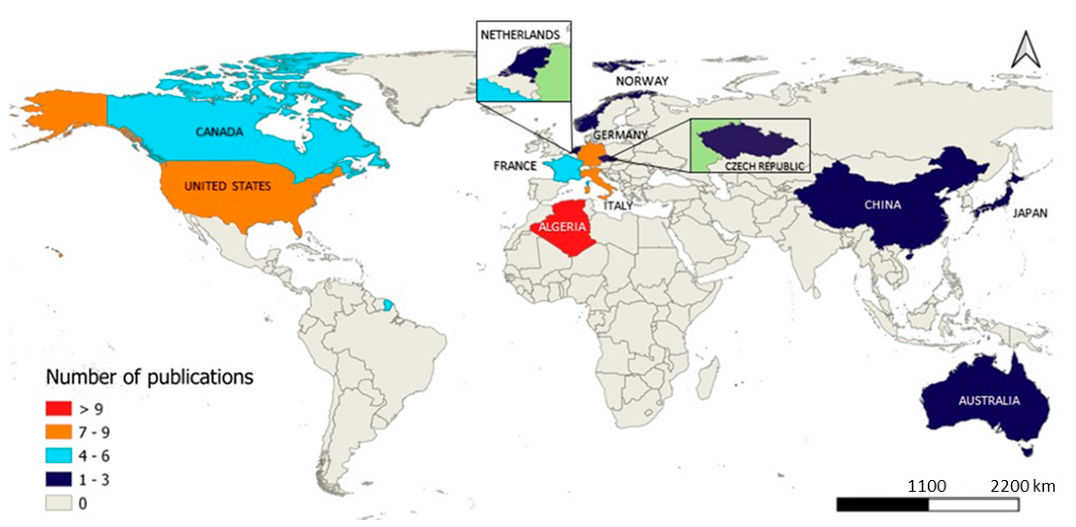
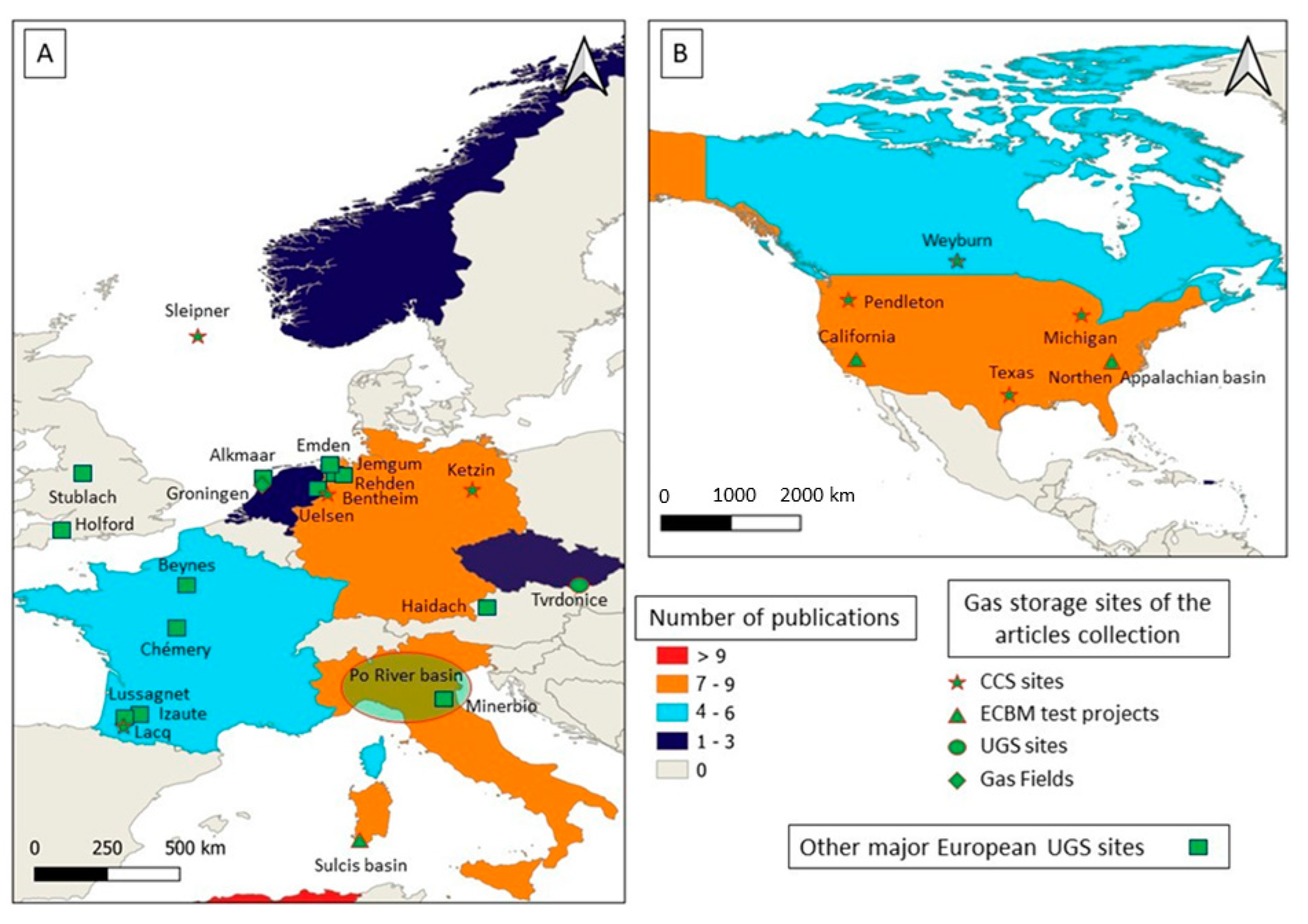
4. Spatial Distribution of Underground CO2 and Natural Gas Storage Projects
- (i)
- Germany with seven scientific publications. Four journal articles focus on the Ketzin pilot site activities preventing greenhouse gas from entering the atmosphere [81,82], on a comparison of seismic interferometry techniques in carbon dioxide sequestration monitoring [83], and on a new concept of using ghost reflections (nonphysical reflection events) retrieved by seismic interferometry for monitoring carbon dioxide storage activities in Bentheim [14]. The other three scientific contributions are conference proceedings focusing on a permanent seismic monitoring system at the Ketzin CCS pilot site [21,50] and a study on monitoring carbon capture and storage areas using micro unmanned aerial vehicles [84];
- (ii)
- The USA, with the same number of contributions, divided into six journal articles and only one conference proceedings. The journal articles refer to the monitoring of the west Texas EOR site [38,60,61], the storage and recovery operations in a confined aquifer located in Pendleton [85], the CO2 storage in a depleted reservoir in Michigan [86], and the monitoring of natural gas storage in the California site [43]. The single conference proceeding focuses on the CCS project of the northern Appalachian basin [62];
- (iii)
- Canada, with a total of six scientific contributions including four publications in international journals [18,19,38,87] and two conference proceedings [88,89]. All the contributions are focused on the monitoring and characterization of the Aquistore CO2 storage project located in Saskatchewan near Weyburn;
- (iv)
- France, with a total contribution of five: three journal articles and two conference proceedings. These articles propose to test the feasibility of long-term surface deformation monitoring by InSAR on carbon dioxide storage projects in European contexts, such as Lorraine, e.g., [90], where studies were conducted but CCS operations were not funded, and the monitoring of flux and soil–gas concentrations at the Lacq-Rousse CCS pilot site [22]. The congress proceedings show the preliminary studies for CO2 injection in the PICOREF sector situated in the Paris basin [59] and a study on the use of persistent scatterers interferometry in highly vegetated/agricultural areas for long-term CO2 storage monitoring [73].
5. Critical Analysis
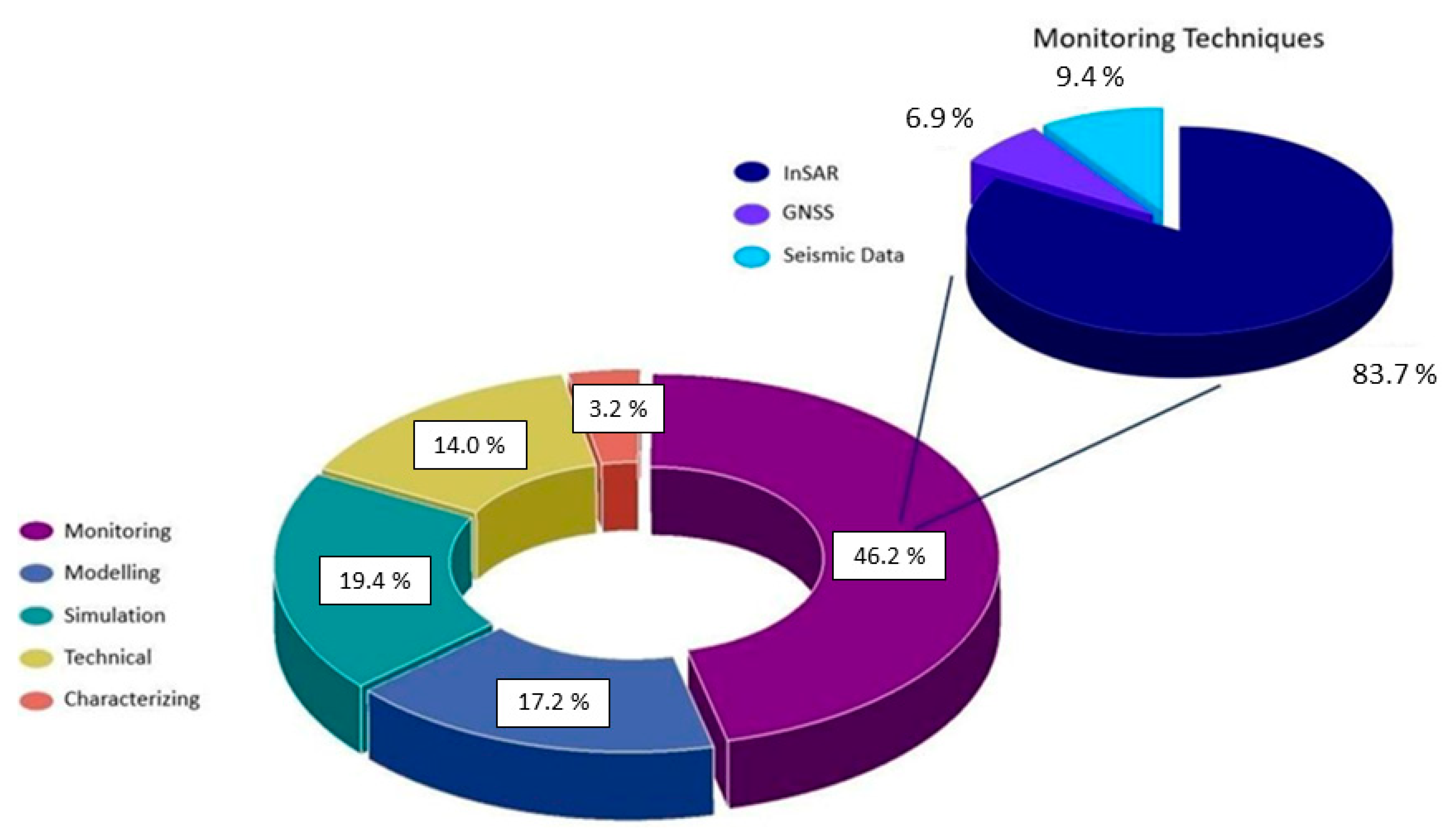
5.1. Aim of the Work and Techniques Used
- Monitoring: activities focusing on LOC detection, ground deformation, reservoir displacement, and subsidence/uplift studies. The monitoring studies were carried out through different techniques, such as InSAR, e.g., [89], seismic reflection and ambient seismic noise, e.g., [82], GPS/GNSS, e.g., [60], pressure analysis, e.g., [66,74,86], tiltmeter, e.g., [19], and geological data, e.g., [33,63];
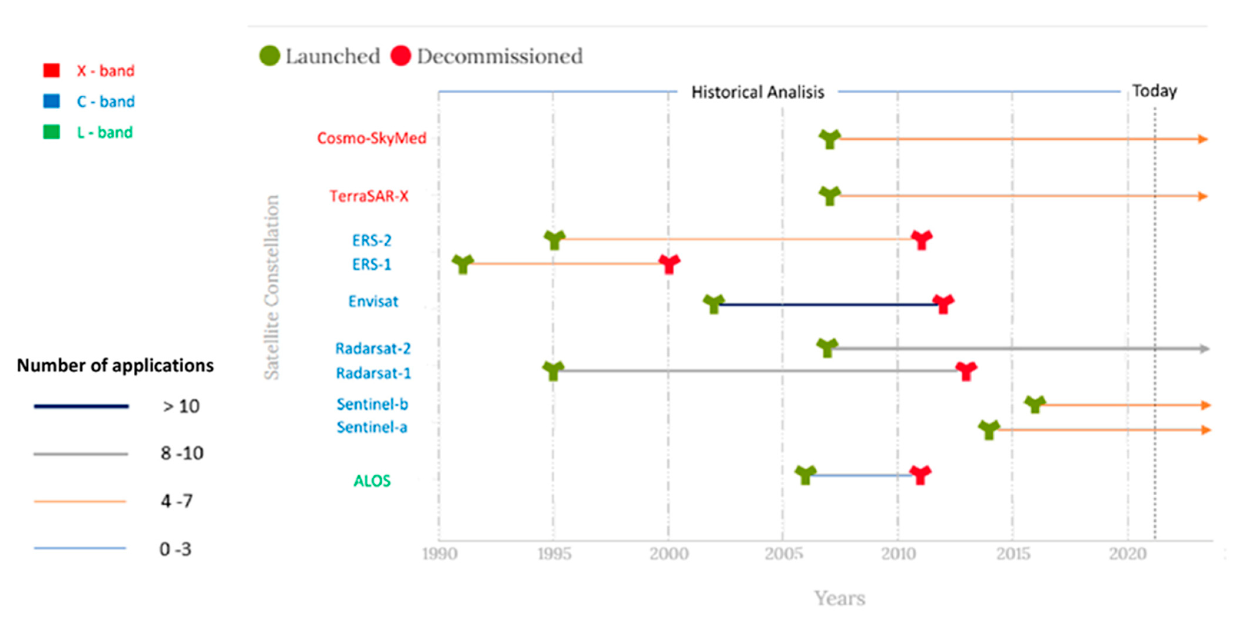
5.2. Satellite SAR Constellations
5.3. Monitoring Techniques
6. Conclusions
7. Future Perspective
Author Contributions
Funding
Acknowledgments
Conflicts of Interest
References
- Tek, M.R. Underground Storage of Natural Gas: Theory and Practice; Springer Science & Business Media: Berlin/Heidelberg, Germany, 1989; Volume 171. [Google Scholar]
- CEDIGAZ: Underground Gas Storage in The World—2021 Status, 19p. Available online: https://www.cedigaz.org/underground-gas-storage-in-the-world-2021-status/ (accessed on 1 April 2022).
- Belcher, S. The Basics of Underground Natural Gas Storage; Eia—U.S. Energy Information Administration: Washington, DC, USA, 2004. [Google Scholar]
- Fernando, A.; Raman, A. Gas storage: An onshore operator’s perspective. Geol. Soc. Lond. Spec. Publ. 2009, 313, 17–24. [Google Scholar] [CrossRef]
- Plaat, H. Underground gas storage: Why and how. Geol. Soc. Lond. Spec. Publ. 2009, 313, 25–37. [Google Scholar] [CrossRef]
- Working Group, I. Climate Change, Intergovernmental Panel on Climate Change; The Physical Science Basis I.; IPCC: Paris, France, 2021. [Google Scholar]
- Rhodes, C.J. The 2015 Paris climate change conference: COP21. Sci. Prog. 2016, 99, 97–104. [Google Scholar] [CrossRef] [PubMed]
- Ryu, J.S.; Jacobson, A.D. CO2 evasion from the Greenland Ice Sheet: A new carbon-climate feedback. Chem. Geol. 2012, 2012, 320–321. [Google Scholar] [CrossRef]
- Pohl, A.; Nardin, E.; Vandenbroucke, T.R.A.; Donnadieu, Y. High dependence of Ordovician Ocean surface circulation on atmospheric CO2 levels. Palaeogeogr. Palaeoclimatol. Palaeoecol. 2016, 458, 39–51. [Google Scholar] [CrossRef]
- Wang, Z.; Yin, J.J.; Pu, J.; Xiao, Q.; Zhang, T.; Li, J. Flux and influencing factors of CO2 outgassing in a karst spring-fed creek: Implications for carbonate weathering-related carbon sink assessment. J. Hydrol. 2021, 596, 125710. [Google Scholar] [CrossRef]
- Yang, D.; Zhang, H.; Li, J. Changes in concentrations of fine and coarse particles under the CO2 induced global warming. Atmos. Res. 2019, 230, 104637. [Google Scholar] [CrossRef]
- European Environmental Agency. European Union Emission Inventory Report 1990–201 under the UNECE Convention on Long-Range Transboundary Air Pollution (LRTAP). European Environmental Agency (EEA) Technical Report No 9; European Environmental Agency: Copenhagen, Denmark, 2019.
- Xie, L.Z.; Zhou, H.W.; Xie, H. Research advance of CO2 storage in rock salt caverns. Rock Soil Mech 2009, 30, 3324–3330. [Google Scholar]
- Dragonov, D.; Heller, K.; Ghose, R. Monitoring CO2 storage using ghost reflections retrieved from seismic interferometry. Int. J. Greenh. Gas Control. 2012, 11, S35–S46. [Google Scholar] [CrossRef]
- Anderson, J.; Bachu, S.; Nimir, H.B.; Basu, B.; Bradshaw, J.; Deguchi, G.; Zhou, D. Underground Geological Storage; Cambridge University Press: Cambridge, UK, 2005. [Google Scholar]
- Riding, J.B.; Rochelle, C.A. Subsurface characterization and geological monitoring of the CO2 injection operation at Weyburn, Saskatchewan, Canada. Geol. Soc. Lond. Spec. Publ. 2009, 313, 227–256. [Google Scholar] [CrossRef]
- Eiken, O.; Ringrose, P.; Hermanrud, C.; Nazarian, B.; Torp, T.A.; Høier, L. Lessons learned from 14 years of CCS operations: Sleipner, In Salah and Snøhvit. Energy Procedia 2011, 4, 5541–5548. [Google Scholar] [CrossRef]
- Verdon, J.P.; Kendall, J.M.; Stork, A.L.; Chadwick, R.A.; White, D.J.; Bissell, R.C. Comparison of geomechanical deformation induced by megatonne-scale CO2 storage at Sleipner, Weyburn, and In Salah. Proc. Natl. Acad. Sci. USA 2013, 110, E2762–E2771. [Google Scholar] [CrossRef] [PubMed]
- Worth, K.; White, D.; Chalaturnyk, R.; Sorensen, J.; Hawkes, C.; Rostron, B.; Young, A. Aquistore project measurement, monitoring, and verification: From concept to CO2 injection. Energy Procedia 2014, 63, 3202–3208. [Google Scholar] [CrossRef]
- Stork, A.L.; Verdon, J.P.; Kendall, J.M. The microseismic response at the In Salah Carbon Capture and Storage (CCS) site. Int. J. Greenh. Gas Control. 2015, 32, 159–171. [Google Scholar] [CrossRef]
- Arts, R.J.; Zhang, X.; Verdel, A.R.; Santonico, D.; Meekes, J.A.C.; Noorlandt, R.P.; Paap, B.F.; Vandeweijer, V.P. Experiences with a permanently installed seismic monitoring array at the CO2 storage site at Ketzin (Germany). A status overview. Energy Procedia 2013, 37, 4015–4023. [Google Scholar] [CrossRef]
- Gal, F.; Pokryszka, Z.; Labat, N.; Michel, K.; Lafortune, S.; Marble, A. Soil-Gas Concentrations and Flux Monitoring at the Lacq-Rousse CO2-Geological Storage Pilot Site (French Pyrenean Foreland): From Pre-Injection to Post-Injection. Appl. Sci. 2019, 9, 645. [Google Scholar] [CrossRef]
- Kapetaki, Z.; Hetland, J.; Le Guenan, T.; Mikunda, T.; Scowcroft, J. Highlights and lessons from the EU CCS demonstration project network. Energy Procedia 2017, 114, 5562–5569. [Google Scholar] [CrossRef]
- Issa, N.A.; Lumley, D.; Peyzner, R. Passive seismic imaging at reservoir depths using ambient seismic noise recorded at the Otway CO2 geological storage research facility. Geophys. J. Int. 2017, 209, 1622–1628. [Google Scholar] [CrossRef]
- De Vries, D.F.H.; Bernardo, C.H. Spatial and Temporal Variability in Atmospheric CO2 Measurements. Energy Procedia 2011, 4, 5573–5578. [Google Scholar] [CrossRef]
- Shi, J.Q.; Imrie, C.; Sinayuc, C.; Durucan, S.; Korre, A.; Eiken, O. Snøhvit CO2 storage project: Assessment of CO2 injection performance through history matching of the injection well pressure over a 32-months period. Energy Procedia 2013, 37, 3267–3274. [Google Scholar] [CrossRef]
- Jung, H.; Singh, G.; Espinoza, N.; Wheeler, M.F. An Integrated Case Study of the Frio CO2 Sequestration Pilot Test for Safe and Effective Carbon Storage Including Compositional Flow and Geomechanics. In Proceedings of the SPE Reservoir Simulation Conference, Montgomery, TX, USA, 20–22 February 2017. [Google Scholar]
- Puri, R.; Yee, D. Enhanced Coalbed Methane Recovery. In Proceedings of the SPE Annual Technical Conference and Exhibition, New Orleans, LA, USA, 23–26 September 1990. [Google Scholar]
- Mazzotti, M.; Pini, R.; Storti, G. Enhanced coalbed methane recovery. J. Supercrit. Fluids 2009, 47, 619–627. [Google Scholar] [CrossRef]
- Wang, K.; Pan, H.Y.; Zhang, T.J.; Wang, H.T. Experimental study on the radial vibration characteristics of a coal briquette in each stage of its life cycle under the action of CO2 gas explosion. Fuel 2022, 320, 123922. [Google Scholar] [CrossRef]
- Norhasyima, R.S.; Mahlia, T.M.I. Advances in CO2 utilization technology: A patent landscape review. J. CO2 Util. 2018, 26, 323–335. [Google Scholar] [CrossRef]
- Niu, Q.; Wang, Q.; Wang, W.; Chang, J.; Chen, M.; Wang, H.; Cai, N.; Fan, L. Responses of multi-scale microstructures, physical-mechanical and hydraulic characteristics of roof rocks caused by the supercritical CO2-water-rock reaction. Energy 2022, 238, 121727. [Google Scholar] [CrossRef]
- Tartarello, M.C.; Plaisant, A.; Bigi, S.; Beaubien, S.E.; Graziani, S.; Lombardi, S.; Ruggiero, L.; De Angelis, D.; Sacco, P.; Maggio, E. Preliminary results of geological characterization and geochemical monitoring of Sulcis Basin (Sardinia), as a potential CCS site. Energy Procedia 2017, 125, 549–555. [Google Scholar] [CrossRef]
- Bank, G.C.; Kuuskraa, V.A. The Economics of Powder River Basin Coalbed Methane Development; U.S. Department of Energy (DOE): Washington, DC, USA, 2007.
- Del Soldato, M.; Confuorto, P.; Bianchini, S.; Sbarra, P.; Casagli, N. Review of works Combining GNSS and InSAR in Europe. Remote Sens. 2021, 13, 1684. [Google Scholar] [CrossRef]
- Sansosti, E.; Casu, F.; Manzo, M.; Lanari, R. Space-borne radar interferometry techniques for the generation of deformation time series: An advanced tool for Earth’s surface displacement analysis. Geophys. Res. Lett. 2010, 37, L20305. [Google Scholar] [CrossRef]
- Benetatos, C.; Codegone, G.; Ferraro, C.; Mantegazzi, A.; Rocca, V.; Tango, G.; Trillo, F. Multidisciplinary Analysis of Ground Movements: An Underground Gas Storage Case Study. Remote Sens. 2020, 12, 3487. [Google Scholar] [CrossRef]
- Zhang, T.; Zhang, W.C.; Yang, R.Z.; Gao, H.R.; Cao, D. Analysis of Available Conditions for InSAR Surface Deformation Monitoring in CCS Projects. Energies 2022, 15, 672. [Google Scholar] [CrossRef]
- Zhang, T.; Zhang, W.C.; Yang, R.Z.; Cao, D.; Chen, L.F.; Li, D.W.; Meng, L.B. CO2 Injection Deformation Monitoring Based on UAV and InSAR Technology: A Case Study of Shizhuang Town, Shanxi Province, China. Remote Sens. 2022, 14, 237. [Google Scholar] [CrossRef]
- Rapant, P.; Struhar, J.; Lazecky, M. Radar Interferometry as a Comprehensive Tool for Monitoring the Fault Activity in the Vicinity of Underground Gas Storage Facilities. Remote Sens. 2020, 12, 271. [Google Scholar] [CrossRef]
- Clarivate, A. Web of science. Clarivate Analytics. 2019. Available online: https://www.webofscience.com/wos/woscc/basic-search (accessed on 22 February 2022).
- Mathieson, A.; Wright, I.; Roberts, D.; Ringrose, P. Satellite imaging to monitor CO2 movement at Krechba, Algeria. Energy Procedia 2009, 1, 2201–2209. [Google Scholar] [CrossRef]
- Vasco, D.W.; Samsonov, S.V.; Wang, K.; Burgmann, R.; Jeanne, P.; Foxall, W.; Zhang, Y.Q. Monitoring natural gas storage using Synthetic Aperture Radar: Are the residuals informative? Geophys. J. Int. 2022, 228, 1438–1456. [Google Scholar] [CrossRef]
- Teatini, P.; Gambolati, G.; Castelletto, N.; Ferronato, M.; Janna, C.; Cairo, E.; Marzorati, D.; Colombo, D.; Ferretti, A.; Bagliani, A.; et al. Monitoring and modelling 3-D ground movements induced by seasonal gas storage in deep reservoirs. Proc. EISOLS 2010, 2010, 339. [Google Scholar]
- Rutqvist, J.; Vasco, D.W.; Myer, L. Coupled reservoir geomechanical analysis of CO2 injection and ground deformation at In Salah, Algeria. Energy Procedia 2009, 1, 1847–1854. [Google Scholar] [CrossRef]
- Vasco, D.W.; Rucci, A.; Ferretti, A.; Novali, F.; Bissel, R.C.; Ringrose, P.S.; Mathieson, A.S.; Wright, I.W. Satellite-based measurements of surface deformation reveal fluid flow associated with the geological storage of carbon dioxide. Geophys. Res. Lett. 2009, 37. [Google Scholar] [CrossRef]
- Onuma, T.; Ohkawa, S. Detection of surface deformation related with CO2 injection by DInSAR at In Salah Algeria. Energy Procedia 2009, 1, 2177–2184. [Google Scholar] [CrossRef]
- Shi, J.Q.; Sinayuc, C.; Durucan, S.; Korre, A. Assessment of carbon dioxide plume behaviour within the storage reservoir and the lower caprock around the KB-502 injection well at In Salah. Int. J. Greenh. Gas Control. 2012, 7, 115–126. [Google Scholar] [CrossRef]
- Shi, J.Q.; Durucan, S.; Korre, A.; Ringrose, P.; Mathieson, A. History matching and pressure analysis with stress-dependent permeability using the In Salah CO2 storage case study. Int. J. Greenh. Gas Control. 2019, 91, 102844. [Google Scholar] [CrossRef]
- Paap, B.; Verdel, A.; Meekes, S.; Steeghs, P.; Vandeweijer, V.; Neele, F. Four years of experience with a permanent seismic monitoring array at the Ketzin CO2 storage pilot site. Energy Procedia 2014, 63, 4043–4050. [Google Scholar] [CrossRef]
- Whittaker, S. IEA GHG Weyburn-Midale CO2 Storage & Monitoring Project. Reg. Carbon Sequestration Partnersh. Annu. Rev. Pet. Technol. Res. Cent. (PTRC) 2010, 5. [Google Scholar]
- Parker, T.; Shatalin, S.; Farhadiroushan, M. Distributed Acoustic Sensing–A new tool for seismic applications. First Break 2014, 32. [Google Scholar] [CrossRef]
- Hartog, A.H. An Introduction to Distributed Optical Fibre Sensors; CRC Press: Boca Raton, FL, USA, 2017. [Google Scholar]
- Bakulin, A.; Silvestrov, I.; Pevzner, R. Surface seismics with DAS: An emerging alternative to modern point-sensor acquisition. Lead. Edge 2020, 39, 808–818. [Google Scholar] [CrossRef]
- Zhang, Y.; Oldenburg, C.M.; Zhou, Q.; Pan, L.; Freifeld, B.M.; Jeanne, P.; Vasco, D.W. Advanced monitoring and simulation for underground gas storage risk management. J. Pet. Sci. Eng. 2021, 208, 109763. [Google Scholar] [CrossRef]
- Jenkins, C.; Chadwick, A.; Hovorka, S.D. The state of the art in monitoring and verification—Ten years on. Int. J. Greenh. Gas Control. 2015, 40, 312–349. [Google Scholar] [CrossRef]
- NETL, N. Carbon dioxide enhanced oil recovery-untapped domestic energy supply and long term carbon storage solution. Energy Lab 2010. Available online: https://www.netl.doe.gov/ (accessed on 6 April 2022).
- Muggeridge, A.; Cockin, A.; Webb, K.; Frampton, H.; Collins, I.; Moulds, T.; Salino, P. Recovery rates, enhanced oil recovery and technological limits. Philosophical Transactions of the Royal Society. Math. Phys. Eng. Sci. 2014, 372, 20120320. [Google Scholar]
- Rohmer, J.; Raucoules, D. On the applicability of Persistent Scatterers Interferometry (PSI) analysis for long term CO2 storage monitoring. Eng. Geol. 2012, 147, 137–148. [Google Scholar] [CrossRef]
- Karegar, M.A.; Dixon, T.H.; Malservisi, R.; Yang, Q.; Hossaini, S.A.; Hovorka, S.D. GPS-based monitoring of surface deformation associated with CO2 injection at an enhanced oil recovery site. Int. J. Greenh. Gas Control 2015, 41, 116–126. [Google Scholar] [CrossRef]
- Yang, Q.; Zhao, W.L.; Dixon, T.H.; Amelung, F.; Han, W.S.; Li, P. InSAR monitoring of ground deformation due to CO2 injection at an enhanced oil recovery site, West Texas. Int. J. Greenh. Gas Control 2015, 41, 20–28. [Google Scholar] [CrossRef]
- Gondle, R.K.; Siriwardane, H.J.; Bajura, R.A.; Winschel, R.A.; Locke, J.E. Ground deformations caused by CO2 injection into a depleted coal seam: Tiltmeter monitoring and geomechanical modelling. In Computer Methods and Recent Advances in Geomechanics: Proceedings of the 14th International Conference of International Association for Computer Methods and Recent Advances in Geomechanics, Kyoto, Japan, 22–25 September 2015; (IACMAG 2014); Taylor & Francis Books Ltd.: Leiden, The Netherlands, 2014; pp. 1391–1396. [Google Scholar]
- Fais, S.; Ligas, P.; Cuccuru, F.; Maggio, E.; Plaisant, A.; Pettinau, A.; Casula, G.; Bianchi, M.G. Detailed petrophysical and geophysical characterization of core samples from the potential caprock-reservoir system in the Sulcis Coal Basin (southwestern Sardinia—Italy). Energy Procedia 2015, 76, 503–511. [Google Scholar] [CrossRef]
- Tamburini, A.; Bianchi, M.; Giannico, C.; Novali, F. Retrieving surface deformation by PSInSAR (TM) technology: A powerful tool in reservoir monitoring. Int. J. Greenh. Gas Control 2010, 4, 928–937. [Google Scholar] [CrossRef]
- Rucci, A.; Vasco, D.W.; Novali, F. Monitoring the geologic storage of carbon dioxide using multicomponent SAR interferometry. Geophys. J. Int. 2013, 193, 197–208. [Google Scholar] [CrossRef]
- Ramirez, A.; Foxall, W. Stochastic inversion of InSAR data to assess the probability of pressure penetration into the lower caprock at In Salah. Int. J. Greenh. Gas Control 2014, 27, 42–58. [Google Scholar] [CrossRef]
- Loschetter, A.; Rohmer, J.; Raucoules, D.; De Michele, M. Sizing a geodetic network for risk-oriented monitoring of surface deformations induced by CO2 injection: Experience feedback with InSAR data collected at In-Salah, Algeria. Int. J. Greenh. Gas Control 2015, 42, 571–582. [Google Scholar] [CrossRef]
- Bohloli, B.; Bjornara, T.I.; Park, J.; Rucci, A. Can we use surface uplift data for reservoir performance monitoring? A case study from In Salah, Algeria. Int. J. Greenh. Gas Control 2018, 76, 200–207. [Google Scholar] [CrossRef]
- Durucan, S.; Shi, J.Q.; Sinayuc, C.; Korre, A. In Salah CO2 storage JIP: Carbon dioxide plume extension around KB-502 well–new insights into reservoir behaviour at the In Salah storage site. Energy Procedia 2011, 4, 3379–3385. [Google Scholar] [CrossRef]
- Ferretti, A.; Tamburini, A.; Novali, F.; Fumagalli, A.; Falorni, G.; Rucci, A. Impact of high-resolution radar imagery on reservoir monitoring. Energy Procedia 2011, 4, 3465–3471. [Google Scholar] [CrossRef]
- Onuma, T.; Okada, K.; Otsubo, A. Time Series Analysis of Surface Deformation related with CO2 Injection by Satellite-borne SAR Interferometry at In Salah, Algeria. Energy Procedia 2011, 4, 3428–3434. [Google Scholar] [CrossRef]
- Shi, J.Q.; Smith, J.; Durucan, S.; Korre, A. A coupled reservoir simulation-geomechanical modelling study of the CO2 injection-induced ground surface uplift observed at Krechba, In Salah. Energy Procedia 2013, 37, 3719–3726. [Google Scholar] [CrossRef]
- Jeremy, R.; Annick, L.; Raucoules, D.; Marcello, D.; Le Gallo, Y.; Raffard, D. On the use of persistent scatterers interferometry (PSI) in highly vegetated/agricultural areas for long term CO2 storage monitoring. In Proceedings of the 2014 IEEE Geoscience and Remote Sensing Symposium; Quebec City, QC, USA,, 13–18 July 2014; pp. 2217–2220. [Google Scholar]
- Guzman, J.D.; Babaei, M.; Shi, J.Q.; Korre, A.; Durucan, S. Coupled flow-geomechanical performance assessment of CO2 storage sites using the Ensemble Kalman Filter. Energy Procedia 2014, 63, 3475–3482. [Google Scholar] [CrossRef]
- Ringrose, P.S.; Mathieson, A.S.; Wright, I.W.; Selama, F.; Hansen, O.; Bissel, R.; Saoula, N.; Midgley, J. The In Salah CO2 storage project: Lessons learned and knowledge transfer. Energy Procedia 2013, 37, 6226–6236. [Google Scholar] [CrossRef]
- GIEAGSI—Gas Infrastructure Europe. Available online: https://agsi.gie.eu/ (accessed on 7 April 2022).
- Teatini, P.; Castelletto, N.; Ferronato, M.; Gambolati, G.; Janna, C.; Cairo, E.; Marzorati, D.; Colombo, D.; Ferretti, A.; Bagliani, A.; et al. Geomechanical response to seasonal gas storage in depleted reservoirs: A case study in the Po River basin, Italy. J. Geophys. Res. Earth Surf. 2011, 116. [Google Scholar] [CrossRef]
- Janna, C.; Castelletto, N.; Ferronato, M.; Gambolati, G.; Teatini, P. A geomechanical transversely isotropic model of the Po River basin using PSInSAR derived horizontal displacement. Int. J. Rock Mech. Min. Sci. 2012, 51, 105–118. [Google Scholar] [CrossRef]
- Jha, B.; Bottazzi, F.; Wojcik, R.; Coccia, M.; Bechor, N.; McLaughlin, D.; Herring, T.; Hager, B.H.; Mantica, S.; Juanes, R. Reservoir characterization in an underground gas storage field using joint inversion of flow and geodetic data. Int. J. Numer. Anal. Methods Geomech. 2015, 39, 1619–1638. [Google Scholar] [CrossRef]
- Codegone, G.; Rocca, V.; Verga, F. Coti. Subsidence Modeling Validation Through Back Analysis for an Italian Gas Storage Field. Geotech. Geol. Eng. 2016, 34, 1749–1763. [Google Scholar] [CrossRef]
- Lubitz, C.; Kempka, T.; Motagh, M. Integrated Assessment of Ground Surface Displacements at the Ketzin Pilot Site for CO2 Storage by Satellite-Based Measurements and Hydromechanical Simulations. IEEE J. Sel. Top. Appl. Earth Obs. Remote Sens. 2019, 12, 186–199. [Google Scholar] [CrossRef]
- Gassenmeier, M.; Sens-Schonfelder, C.; Delatre, M.; Korn, M. Monitoring of environmental influences on seismic velocity at the geological storage site for CO2 in Ketzin (Germany) with ambient seismic noise. Geophys. J. Int. 2015, 200, 524–533. [Google Scholar] [CrossRef]
- Cao, H.T.; Askari, R. Comparison of seismic interferometry techniques for the retrieval of seismic body waves in CO2 sequestration monitoring. J. Geophys. Eng. 2019, 16, 1094–1115. [Google Scholar] [CrossRef]
- Neumann, P.P.; Asadi, S.; Bennetts, V.H.; Lilienthal, A.J.; Bartholmai, M. Monitoring of CCS Areas using Micro Unmanned Aerial Vehicles (MUAVs). Energy Procedia 2013, 37, 4182–4190. [Google Scholar] [CrossRef][Green Version]
- Bonneville, A.; Heggy, E.; Strickland, C.; Normand, J.; Dermond, J.; Fang, Y.L.; Sullivan, C. Geophysical Monitoring of Ground Surface Deformation Associated with a Confined Aquifer Storage and Recovery Operation. Water Resour. Manag. 2015, 29, 4667–4682. [Google Scholar] [CrossRef]
- Raziperchikolaee, S.; Cotter, Z.; Gupta, N. Assessing mechanical response of CO2 storage into a depleted carbonate reef using a site-scale geomechanical model calibrated with field tests and InSAR monitoring data. J. Nat. Gas Sci. Eng. 2021, 86, 103744. [Google Scholar] [CrossRef]
- Samsonov, S.; Czarnogorska, M.; White, D. Satellite interferometry for high-precision detection of ground deformation at a carbon dioxide storage site. Int. J. Greenh. Gas Control 2015, 42, 188–199. [Google Scholar] [CrossRef]
- Czarnogorska, M.; Samsonov, S.; White, D. Ground Deformation Monitoring Using RADARSAT-2 DInSAR-MSBAS at the Aquistore CO2 Storage site in Saskatchewan (Canada). International Archives of the Photogrammetry. In Proceedings of the ISPRS Technical Commission I Symposium, Denver, CO, USA, 17–20 November 2014. [Google Scholar]
- Czarnogorska, M.; Samsonov, S.; White, D.; Decker, V. Ground Deformation at the Aquistore CO2 Storage Site in Saskatchewan (Canada) Measured by RADARSAT-2 DINSAR. In AGU Fall Meeting Abstracts; IEEE: Manhattan, NY, USA, 2014; Volume 2014, pp. 445–447. [Google Scholar]
- Raucoules, D.; Raffard, D.; Rohmer, J.; Loschetter, A.; De Michele, M.; Le Gallo, Y. Potential of diffuse scatterer interferometry for monitoring CO2 storage sites in European contexts (land cover types). Int. J. Remote Sens. 2015, 36, 2800–2815. [Google Scholar] [CrossRef]
- Guo, S.C.; Zheng, H.R.; Yang, Y.J.; Zhang, S.L.; Hou, H.P.; Zhu, Q.L.; Du, P.J. Spatial estimates of surface deformation and topsoil moisture in operating CO2-EOR project: Pilot environmental monitoring using SAR technique. J. Clean. Prod. 2019, 236, 117606. [Google Scholar] [CrossRef]
- Yang, H.; Qin, Y.; Feng, G.F.; Ci, H. Online Monitoring of Geological CO2 Storage and Leakage Based on Wireless Sensor Networks. IEEE Sens. J. 2013, 13, 556–562. [Google Scholar] [CrossRef]
- Hu, B. Monitoring of Ground Deformation due to Excessive Withdrawal of Natural Gas Using SBAS. Math. Probl. Eng. 2014, 2014, 674510. [Google Scholar] [CrossRef]
- Gee, D.; Sowter, A.; Novellino, A.; Marsh, S.; Gluyas, J. Monitoring land motion due to natural gas extraction: Validation of the Intermittent SBAS (ISBAS) DInSAR algorithm over gas fields of North Holland, the Netherlands. Mar. Pet. Geol. 2016, 77, 1338–1354. [Google Scholar] [CrossRef]
- Whaley, J. The Groningen gas field. GEO ExPro Mag. 2009, 6. Available online: https://www.geoexpro.com/articles/2009/04/the-groningen-gas-field (accessed on 20 September 2022).
- Mulder, M.; Perey, P. Gas Production and Earthquakes in Groningen; Reflection on Economic and Social Consequences; Policy Papers; Centre for Energy Economics Research, University of Groningen: Groningen, The Netherlands, 2018; Volume 3. [Google Scholar]
- Dost, B.; Ruigrok, E.; Spetzler, J. Development of seismicity and probabilistic hazard assessment for the Groningen gas field. Neth. J. Geosci. 2017, 96, s235–s245. [Google Scholar] [CrossRef]
- Ruigrok, E.; Domingo-Ballesta, J.; van den Hazel, G.J.; Dost, B.; Evers, L. Groningen explosion database. First Break. 2019, 37, 37–41. [Google Scholar] [CrossRef]
- Rinaldi, A.P.; Rutqvist, J. Modeling of deep fracture zone opening and transient ground surface uplift at KB-502 CO2 injection well, In Salah, Algeria. Int. J. Greenh. Gas Control 2012, 12, 155–167. [Google Scholar] [CrossRef]
- Mokhatab, S.; Poe, W.A.; Mak, J.Y. Handbook of Natural Gas Transmission and Processing: Principles and Practices; Gulf Professional Publishing: Houston, TX, USA, 2018. [Google Scholar]
- Chakrabarty, A.; Mannan, S.; Cagin, T. Multiscale Modeling for Process Safety Applications; Butterworth-Heinemann: Waltham, MA, USA, 2015. [Google Scholar]
- Miyazaki, B. Well integrity: An overlooked source of risk and liability for underground natural gas storage. Lessons learned from incidents in the USA. Geol. Soc. Lond. Spec. Publ. 2009, 313, 163–172. [Google Scholar] [CrossRef]
- Thorpe, A.K.; Duren, R.M.; Conley, S.; Prasad, K.R.; Bue, B.D.; Yadav, V.; Miller, C.E. Methane emissions from underground gas storage in California. Environ. Res. Lett. 2020, 15, 045005. [Google Scholar] [CrossRef]
- Freifeld, B.M.; Oldenburg, C.M.; Jordan, P.; Pan, L.; Perfect, S.; Morris, J.; Rose, K. Well Integrity for Natural Gas Storage in Depleted Reservoirs and Aquifers (No. LBNL-1006165); Lawrence Berkeley National Lab. (LBNL): Berkeley, CA, USA, 2016. [Google Scholar]
- Pan, L.; Oldenburg, C.M.; Freifeld, B.M.; Jordan, P.D. Modeling the Aliso Canyon underground gas storage well blowout and kill operations using the coupled well-reservoir simulator T2Well. J. Pet. Sci. Eng. 2018, 161, 158–174. [Google Scholar] [CrossRef]
- Bruno, M.S.; Dusseault, M.B.; Balaa, T.T.; Barrera, J.A. Geomechanical analysis of pressure limits for gas storage reservoirs. Int. J. Rock Mech. Min. Sci. 1998, 35, 569–571. [Google Scholar] [CrossRef]
- Bruno, M.S.; Lao, K.; Diessl, J.; Childers, B.; Xiang, J.; White, N.; van der Veer, E. Development of improved caprock integrity analysis and risk assessment techniques. Energy Procedia 2014, 63, 4708–4744. [Google Scholar] [CrossRef]
- Lanari, R.; Lundgren, P.; Manzo, M.; Casu, F. Satellite radar interferometry time series analysis of surface deformation for Los Angeles, California. Geophys. Res. Lett. 2014, 31. [Google Scholar] [CrossRef]
- Gatelli, F.; Guamieri, A.M.; Parizzi, F.; Pasquali, P.; Prati, C.; Rocca, F. The wavenumber shift in SAR interferometry. IEEE Trans. Geosci. Remote Sens. 1994, 32, 855–865. [Google Scholar] [CrossRef]
- Zebker, H.A.; Rosen, P.A.; Hensley, S. Atmospheric effects in interferometric synthetic aperture radar surface deformation and topographic maps. J. Geophys. Res. Solid Earth 1997, 102, 7547–7563. [Google Scholar] [CrossRef]
- Zebker, H.A.; Villasenor, J. Decorrelation in interferometric radar echoes. IEEE Trans. Geosci. Remote Sens. 1992, 30, 950–959. [Google Scholar] [CrossRef]
- Torres, R.; Snoeij, P.; Geudtner, D.; Bibby, D.; Davidson, M.; Attema, E.; Rostan, F. GMES Sentinel-1 mission. Remote Sens. Environ. 2012, 120, 9–24. [Google Scholar] [CrossRef]
- Showstack, R. Sentinel Satellites Initiate New Era in Earth Observation; Wiley: Hoboken, NJ, USA, 2014; pp. 239–240. [Google Scholar]
- Polidori, L.; Bacci, P.A.; Simonetto, E.; Morel, L.; Durand, F.; Durand, S.; Nicolas, J. On the Potential of GPS-InSAR Combination to Improve the Accuracy of Ground Deformation Monitoring: Simulation-Based Validation. In Proceedings of the Anais XVI Simpósio Brasileiro de Sensoriamento Remoto-SBSR, Foz do Iguaçu, PR, Brasil, 13–18 April 2013; INPE; Volume 16, pp. 8467–8474. [Google Scholar]
- Murdoch, L.C.; Germanovich, L.N.; DeWolf, S.J.; Moysey, S.M.; Hanna, A.C.; Kim, S.; Duncan, R.G. Feasibility of using in situ deformation to monitor CO2 storage. Int. J. Greenh. Gas Control 2020, 93, 102853. [Google Scholar] [CrossRef]
- Davis, T.L.; Landrø, M.; Wilson, M. Geophysics and Geosequestration; Cambridge University Press: Cambridge, UK, 2019. [Google Scholar]
- Anyosa, S.; Bunting, S.; Eidsvik, J.; Romdhane, A.; Bergmo, P. Assessing the value of seismic monitoring of CO2 storage using simulations and statistical analysis. Int. J. Greenh. Gas Control 2021, 105, 103219. [Google Scholar] [CrossRef]
- Kirkland, C.M.; Thane, A.; Hiebert, R.; Hyatt, R.; Kirksey, J.; Cunningham, A.B.; Phillips, A.J. Addressing wellbore integrity and thief zone permeability using microbially-induced calcium carbonate precipitation (MICP): A field demonstration. J. Pet. Sci. Eng. 2020, 190, 107060. [Google Scholar] [CrossRef]
- Tariq, Z.; Mahmoud, M.; Abdulraheem, A. Real-time prognosis of flowing bottom-hole pressure in a vertical well for a multiphase flow using computational intelligence techniques. J. Pet. Explor. Prod. Technol. 2020, 10, 1411–1428. [Google Scholar] [CrossRef]
- Tanaka, Y.; Sawada, Y.; Tanase, D.; Tanaka, J.; Shiomi, S.; Kasukawa, T. Tomakomai CCS demonstration project of Japan, CO2 injection in process. Energy Procedia 2017, 114, 5836–5846. [Google Scholar] [CrossRef]
- Lewicki, J.L.; Hilley, G.E. Eddy covariance mapping and quantification of surface CO2 leakage fluxes. Geophys. Res. Lett. 2009, 36. [Google Scholar] [CrossRef]
- Dafflon, B.; Barrash, W. Three-dimensional stochastic estimation of porosity distribution: Benefits of using ground-penetrating radar velocity tomograms in simulated-annealing-based or Bayesian sequential simulation approaches. Water Resour. Res. 2012, 48. [Google Scholar] [CrossRef]
- Hureau, G.; General, S. Gas Storage in Europe, Recent Developments and Outlook to 2035. In Proceedings of the European Gas Conference, Vienna, Austria, 27–29 January 2015. [Google Scholar]
- Tomás, R.; Li, Z.; Lopez-Sanchez, J.M.; Liu, P.; Singleton, A. Using wavelet tools to analyse seasonal variations from InSAR time-series data: A case study of the Huangtupo landslide. Landslides 2016, 13, 437–450. [Google Scholar] [CrossRef]
- IEAGHG—Monitoring Selection Tool. Available online: https://ieaghg.org/ccs-resources/monitoring-selection-tool (accessed on 4 July 2022).
- Page, B.; Turan, G.; Zapantis, A.; Burrows, J.; Consoli, C.; Erikson, J.; Havercroft, I.; Kearns, D.; Liu, H.; Rassool, D.; et al. The Global Status of CCS 2020: Vital to Achieve Net Zero; Global CSS Institute: Melbourne, Australia, 2020. [Google Scholar]


| Technique | Number of Applications | Type of Analysis |
|---|---|---|
| GPS-GNSS | 14 | Combined with InSAR or Geological Data, e.g., [39,64,85] |
| Seismic | 17 | 3D Seismic, e.g., [37] Seismic Reflection, e.g., [14] Ambient Seismic Noise, e.g., [44] Ambient Seismic Data, e.g., [18] 2D Seismic Data, e.g., [83] |
| Pressure Analysis | 12 | Well-Head Pressure, e.g., [66] Bottom-Hole Pressure, e.g., [44,74,79] Flowing Bottom-Hole Pressure, e.g., [86] |
| UAV | 5 | Drone gas leak monitoring, e.g., [25,80] |
| GWL | 4 | Comparison of GWL with Seismic Velocity, e.g., [78] |
| Tiltmeter | 3 | Ground Deformation Monitoring, e.g., [52] |
| Wireless Sensor Networks | 1 | Monitoring CO2 Storage and Leakage [92] |
| Geochemical Baseline | 1 | Geological Characterization [33] |
Disclaimer/Publisher’s Note: The statements, opinions and data contained in all publications are solely those of the individual author(s) and contributor(s) and not of MDPI and/or the editor(s). MDPI and/or the editor(s) disclaim responsibility for any injury to people or property resulting from any ideas, methods, instructions or products referred to in the content. |
© 2022 by the authors. Licensee MDPI, Basel, Switzerland. This article is an open access article distributed under the terms and conditions of the Creative Commons Attribution (CC BY) license (https://creativecommons.org/licenses/by/4.0/).
Share and Cite
Fibbi, G.; Del Soldato, M.; Fanti, R. Review of the Monitoring Applications Involved in the Underground Storage of Natural Gas and CO2. Energies 2023, 16, 12. https://doi.org/10.3390/en16010012
Fibbi G, Del Soldato M, Fanti R. Review of the Monitoring Applications Involved in the Underground Storage of Natural Gas and CO2. Energies. 2023; 16(1):12. https://doi.org/10.3390/en16010012
Chicago/Turabian StyleFibbi, Gabriele, Matteo Del Soldato, and Riccardo Fanti. 2023. "Review of the Monitoring Applications Involved in the Underground Storage of Natural Gas and CO2" Energies 16, no. 1: 12. https://doi.org/10.3390/en16010012
APA StyleFibbi, G., Del Soldato, M., & Fanti, R. (2023). Review of the Monitoring Applications Involved in the Underground Storage of Natural Gas and CO2. Energies, 16(1), 12. https://doi.org/10.3390/en16010012