Article

Metal–Organic Frameworks (MOFs) Containing Adsorbents for Carbon Capture

1
Department of Environmental Science, University of Latvia, LV-1004 Riga, Latvia
2
Laboratory of Molecular Crystals, Faculty of Chemistry, University of Latvia, LV-1004 Riga, Latvia
3
Laboratory of Materials Morphology and Structure Investigations, Institute of Solid State Physics, University of Latvia, LV-1063 Riga, Latvia
*
Authors to whom correspondence should be addressed.
Energies 2022, 15(9), 3473; https://doi.org/10.3390/en15093473
Submission received: 1 March 2022 / Revised: 3 May 2022 / Accepted: 5 May 2022 / Published: 9 May 2022
(This article belongs to the Special Issue Carbon Capture, Utilisation and Storage)

Abstract

:
In this study, new composite materials of montmorillonite, biochar, or aerosil, containing metal–organic frameworks (MOF) were synthesized in situ. Overall, three different MOFs—CuBTC, UTSA-16, and UiO-66-BTEC—were used. Obtained adsorbents were characterized using powder X-ray diffraction, thermogravimetric analysis, nitrogen adsorption porosimetry, scanning electron microscopy, energy-dispersive X-ray spectroscopy, and Fourier transform infrared spectrophotometry. Additionally, the content of metallic and nonmetallic elements was determined to investigate the crystalline structure, surface morphology, thermal stability of the obtained MOF-composites, etc. Cyclic CO2 adsorption analysis was performed using the thermogravimetric approach, modeling adsorption from flue gasses. In our study, the addition of aerosil to CuBTC (CuBTC-A-15) enhanced the sorbed CO2 amount by 90.2% and the addition of biochar (CuBTC-BC-5) increased adsorbed the CO2 amount by 75.5% in comparison to pristine CuBTC obtained in this study. Moreover, the addition of montmorillonite (CuBTC-Mt-15) increased the adsorbed amount of CO2 by 27%. CuBTC-A-15 and CuBTC-BC-5 are considered to be the most perspective adsorbents, capturing 3.7 mmol/g CO2 and showing good stability after 20 adsorption-desorption cycles.

1. Introduction

Carbon dioxide (CO2) is a major greenhouse gas, which is reflecting infrared radiation back to Earth’s surface, thus resulting in global warming. Atmospheric CO2 concentration has increased since the preindustrialization era from 280 ppm to 409 ppm in 2021, and according to modeling results it could reach a level of 670 ppm by 2100 [1]. Increased atmospheric CO2, as well as other greenhouse gas concentrations, are resulting in global warming, with a number of secondary effects such as a change of hydrological cycle, increased occurrence of extreme climate events, sea-level rise, impacts on agricultural production, and others. To reduce the impacts of climate change, global warming mitigation activities are needed, such as increasing the efficiency of energy use, promoting alternative sources of energy instead of fossil fuels, as well as taking a number of other actions [2] as indicated in recent political declarations of the EU [3] and other nations. However, depending on the emission source structure as well as other factors, to reach ambitious political aims, the development of CO2 capture, storage, and utilization techniques can provide major input to reach greenhouse gas emission reduction aims [4]. The aim of carbon capture (CC) is to address emissions mostly coming from the burning of fossil fuels in the energy production and transport sectors with the following storage, for example, in the geological environment (depleted air/gas/water reservoirs, other geological structures), thus mitigating inevitable emissions [5]. The next step [6] of the CC concept is to develop approaches how to use CO2 as source material for other substances, thus transforming waste products of human activities into a resource for other products (carbon capture, storage, and utilization (CCSU)) [7].
CO2 capture technologies have been intensively studied during the last decades and for now, the most elaborated approaches include: (1) cryogenic separation process (condensation) of CO2 from other gases [8]; (2) use of selective membranes for separation of CO2 flows [9]; (3) electrochemical separation; and (4) chemical (physical) absorption of CO2 with different sorbents in both liquid and solid phases [10,11,12]. From many aspects, absorption is a favorable technology as organic or inorganic adsorbents are available with high selectivity in respect to CO2, high efficiency and stability during exploitation, as well as low energy consumption [12,13,14]. The range of CC materials studied so far is remarkably wide and the choice of materials mainly evaluates the CO2 adsorption capacity and reversibility of CO2 adsorption-release, so that they can be used in many cycles without loss of activity. For example, alkali solutions, alkali solid materials, and organic–inorganic hybrid materials that are chemically capable of binding CO2 are highly efficient. Some of the most popular materials are chemically or physically supported amines at metal oxides or solid porous materials [15]. The main disadvantage of these materials is the high energy consumption required for regeneration, which is why the development of physical sorbents to achieve superior performance is a promising direction. Physical sorbents such as porous zeolites, silica, activated carbon, and others are recoverable at lower temperatures (and therefore require less energy and usage) are more sustainable, but the disadvantages of these materials are due to the high CO2 partial pressures required to be effective [15]. One of the most promising groups of adsorbents for CC can be considered metal–organic frameworks (MOFs) with three-dimensional, microporous materials with crystalline structures [16,17]. MOFs can be considered as metal–ligand networks composed of ligands attached by means of co-ordination bonds to metal atoms located in an MOF center. So, by changing the structure of ligands and metal atoms, a number of MOF structures have been created with designed pore and channel sizes from angstroms to nanometers, large surface areas, and a wide variety of structures responsible for CO2 sorption, and large void volumes for storage [11]. Possibilities to design the MOF structures is a key factor in ensuring high MOF-adsorbent selectivity in respect to other gasses present, such as in flue gas (H2, N2, O2, CH4, and CO) [11,18].
CuBTC—copper (II) benzene-1,3,5-tricarboxylate (C18H6Cu3O12), also known as HKUST-1, is a highly porous MOF of [Cu3(BTC)2(H2O)3]n, that contains interconnected [Cu2(O2CR)4] units, where R is an aromatic ring. The accessible porosity of the 3D framework reaches 40% of the solid with a channel pore size of 1 nm [19]. CuBTC is one of the most studied MOFs with open metal sites (unsaturated Cu centers) that is believed to promote the attraction of small gas molecules, especially polar molecules including water. As the flue gases contain about 5–7 vol% of water vapor, the practical application of CuBTC could be complex. As an important disadvantage of CuBTC is its high sensitivity to moisture, several techniques have been used to improve the hydrolytic properties of the material, including modification by the introduction of hydrophobic functional groups and coating with hydrophobic compounds, but although highly effective in improving hydrolytic stability, the disadvantage was the lengthy synthetic procedures or complex equipment and harsh synthesis conditions, thus hampering practical application [20]. CuBTC has been used for the adsorption of various gases (CO2, CO, CH4, H2, O2, N2) [21], though to improve its properties various carbon-containing [22,23,24] and clay-containing [25] composites of this MOF have been studied.
UTSA-16 (UTSA = University of Texas at San Antonio) is another MOF with the empirical formula K2Co3(C6H4O7)2, and it is characterized by a large proportion of open metal sites. Its advantages include excellent adsorption capacity for the capture and removal of CO2 with high selectivity at ambient conditions with a relatively simple recovery step, remarkable volumetric capacity, as well as the employment of cheap raw materials for its synthesis involving affordable precursors and nontoxic solvents, which in economic terms can facilitate the scaling up of the synthesis. Moreover, it is quite stable in the presence of water [26]. UTSA-16 is a selective adsorbent for CO2 capture and purification of H2, and it has raised interest due to its magnetic properties, and a composite of UTSA-16 and graphene oxide is used for biogas decarburization [27,28,29]. Thermal stability is cited as one of the disadvantages of UTSA-16 that could be improved by forming composites, such as with graphene oxide [30].
The UiO-66 (UiO = University of Oslo) class involves Zr6O4(OH)4 octahedral nodes that form latices in an ideal 12-fold co-ordination with dicarboxylic linkers resulting in a cubic, close-packed unit cell structure. To date, CO2 capture capacities for UiO-66 with incorporated functionalities have been relatively extensively studied. In addition, the range of functionality is extremely wide, including amine, alkyl, acid, hydroxy functionalized UiO-66 composites, metal-exchange functionalized UiO-66, and others. According to review by Usman et al. [31], CO2 capacity of mentioned materials varies from 2.7 wt% (UiO-66-(COOK)4-EX, 298 K) to 25.6 wt% (UiO-66-(CH3)2, 273 K). The MOFs of UiO-66 class are characterized by excellent chemical, thermal and mechanical properties [32]. Moreover, UiO-66(Zr)-COOH)2 are considered to be very stable with high selectivity for CO2/N2 separation, high working capacity, and efficient recyclability [33]. Studies published by other authors confirm the selectivity of this Zr-containing MOF, indicating that UiO-66(Zr)-(COOH)2 has the highest CO2 adsorption capacity compared to other studied gases (CH4, N2, CO, and H2). The amount of CO2 adsorbed at 303 K, 0.99 bar reaches 1.05 mmol/g [34]. One of the most important limiting factors for the effective practical use of all MOFs studied is their processability due to their inherent powdery nature.
Although MOFs show very promising physical and chemical properties for various applications, their properties can be further improved by several means. Overall, studies published so far highlight the drawbacks of MOFs’ potential practical applications. For example, some MOFs are characterized by poor chemical stability, low yields, low thermal and hydrolytic stability, potentially high production costs, and large pore space, which does not favor gas molecules storage [35,36]. To improve CO2 adsorption, different MOF modification approaches including presynthesis and postsynthesis are used. The main criterion for using MOF-composites is the synergistic effects of MOF and carrier material on their adsorption behaviors. To date, various materials have been combined with MOFs to improve CO2 adsorption properties, which can be divided into following classes [37], which include small molecules, such as ionic liquids (ILs) [38,39,40]; polymeric materials, such as polyethyleneimine (PEI) [41,42]; flat materials, such as graphene [43], graphene oxide [44,45,46], aminoclays [25] etc.; and spatial materials such as carbon nanotubes (CNTs) [37,47]. Overall, MOFs and MOF-composites have found applications in catalysts, supercapacitors, adsorbents, sensors, environmental protection, drug delivery, etc. [48].
Recently, the incorporation of carbon-based compounds to MOFs to produce MOF-carbon composites has been intensively studied. MOF-carbon composites can be considered as a new material that combines the advantages of MOFs, such as well-defined structure and texture properties, high porosity, etc., and properties of carbon-based materials, such as high mechanical and elastic strength, chemical and thermal stability, low weight, low toxicity, and low costs. Such new functionality could be obtained after synergetic interaction between the MOF matrix and the carbon matrix due to changes in chemical composition, structure, and porosity [49]. Functionalities of the C-containing MOF-composites including structure change, enhanced stabilities, and template effects are vital to meet the prerequisites in practical occasions and enrich the prospective contents of MOFs [50]. According to the literature, the application of some adsorbents with high surface areas, such as graphite, graphene, graphene oxide (GO), and carbon nanotubes, significantly improves the gas adsorption performances of the MOF-composites by optimizing the texture and morphology of the solid to create an additional microporosity and interstitial porosity [11,50,51,52,53,54,55,56,57,58,59,60,61]. This promotes the gas transport to the adsorption sites and increases total accessible pore volumes. Recent studies report that due to the formation of secondary micro- and mesoporosities in the nanostructure of composite materials, carbon-doped MOF-composites are able to increase gas adsorption capacity and separation efficiency compared to their parent material [52,53]. For instance, Szcznesniak and Choma reported that graphene containing CuBTC composites are potential materials for large-scale selective CO2 capture at ambient conditions. They found that most graphene-containing composites show lower adsorption capacities; nevertheless, they exhibit an enhanced CO2/N2 selectivity in comparison to bare samples [54]. It has been reported that GO, as well as other materials, can act as a substrate or template in the formation of MOF-composites; for example, oxygen-containing functional groups of GO can act as seed sites for crystallization and HKUST-1 nanocrystal dispersion. Studies also indicate that GO affects the growth of MOF nanocrystals. The optimal addition of GO allows for the obtainment of a composite with a larger specific surface area, as well as to increase the CO2 adsorption capacity compared to pristine HKUST-1 [44]. Shen et al. reported that UTSA-16-GO composites have improved thermal stability, and that CO2/CH4 selectivity is three times higher compared with UTSA-16 alone [30]. As with GO, carboxylate groups of CNTs are reported to act as nucleation sites to support continuous growth of HKUST-1 [52]. CNT-containing composites also have higher CO2 adsorption capacities in comparison to pristine MOF, e.g., the CO2 uptake at 298 K, 18 bar for CNT@Cu3(BTC)2 reach 595 mg/g, which is more than that of pristine MOF (295 mg/g) at the same conditions [57]. So far, MOF-carbon composites containing graphene [45], graphene oxide (GO) [44,45,48,54,56,58], graphene aerogel [23], and carbon nanotubes (CNT) [55,57] have been intensively studied, but less attention has been paid to biochar as a potential carbon-containing MOF-composite. Yet, several definitions of biochar [51] have been proposed, but according to IBI [60], biochar is the solid material derived from various biomass feedstocks under oxygen-limited thermal conversion processes. Biochar is characterized by a porous structure, abundant functional groups, various inorganic nutrients, and high carbon stability. Therefore, biochar can be used for a variety of purposes, including immobilization of pollutants, flue gas purification, and in situ carbon storage [61]. It is quite similar to activated carbon, which is also produced by pyrolysis, with a characteristic medium or large surface areas. However, unlike activated carbon, biochar is usually not activated or processed. In addition, biochar contains a noncarbonated fraction that can interact with other substances. In particular, the amount of O-containing carboxyl groups, hydroxyl groups, and phenolic surface functional groups in biochar could effectively be able to co-ordinate with the metallic centers of MOFs, leading to the growth of MOF crystals onto biochar [51,52]. The biochar component in the MOF-biochar composite could enhance the mechanical strength of the composite as well as serve as secondary adsorption sites.
Aerosil, or fumed silica, is synthetic amorphous silicon dioxide—nonporous 3D material with a high surface area. Like C-containing MOF-composites, SiO2-containing MOF-composites combine the advantages of two matrices (SiO2 and MOF), as well as new perspective properties which it can possess due to the synergistic effect. The presence of silica materials can increase the porosity of new materials and provide more active sites, thus promoting the application in adsorption and elsewhere. Moreover, silicas have high stability and can be considered as low-cost materials. Therefore, the combination of MOFs and porous or nonporous silicas can enhance the stability and properties of new composites as well as provide a platform for widespread use [62]. Literature studies indicate that there are several attempts to produce MOF-silica composites, using HKUST-1, MIL-68, MIL-101(Cr), ZIF-8, MOF-5, etc., and SBA-15 [24], MCM-41 [63], MSU, etc., which are described in detail in various reviews [62,64]. Chen et al. have studied HKUST-1 and its composites with different contents of SBA-15 [24] and reported that the interactions between surface silanol groups and metal centers induced structural changes, resulting in an increase in surface area and micropore volume, and inferring from that, the composite with the most optimal SBA-15 content was able to adsorb for almost 16% more CO2 than pristine HKUST-1. Another study concluded that the adsorbent containing CuBTC and MCM-41 is able to adsorb 20% more CO2 than MCM-41, and the resulting composite has increased CO2/CH4 selectivity [63]. Generally, MOF-silica composites exhibit improved properties that can be attributed to the synergetic effect compared to pristine MOFs and silicas [24,62]. In addition to the already mentioned materials, MOF hybrid sorbents containing various natural materials, such as zeolites, are also being studied. Lestari et al. [65] reported that although the specific surface area of the resulting composite has decreased due to the interaction of Indonesian natural zeolite and CuBTC, it is still able to adsorb 12% more CO2 than the initial materials.
Clay minerals are ubiquitous and are capable of interlayer and surface adsorption of CO2. In addition, their modification allows for the improvement of CO2 adsorption capabilities even more. The prospects of the most widely available clay minerals in the Baltic States for large-scale CO2 emission reduction and suitable alternative approaches for clay modification to improve CO2 adsorption capacity can be found in review [66]. Recently, clay-containing MOF-composites have been studied for various purposes. The main goal of clay-MOF-composites is to improve the properties of MOF, which would allow them to be used more efficiently in various fields. For instance, Xie et al. [67] have improved CuBTC with higher hydrothermal stability and catalytic activity by hybridization of CuBTC with natural clay attapulgite and montmorillonite affecting the size of Zn-BDC crystals [68] and improving the thermal stability of MOF-5 [69]. The improvement of hydrolytic stability is based on two types of co-ordination between MOF and clay. The -OH groups on the clay surface can co-ordinate with metal ions in MOFs, such as Cu in CuBTC, while the carboxyl groups of CuBTC can inversely chelate the Mg2+ and Al3+ of the clay [67]. Compared with GO, CNT, GA, and others, eco-friendly and low-cost natural materials could be preferable as filler additives. Articles published so far show that clay-containing materials can serve as a template for in situ MOF-composite synthesis [25,69]. Aminoclay (aminopropyl functionalized Mg phyllosilicate) has been used to stabilize in situ synthesized CuBTC, and CO2 adsorption capacity was 39% higher than that of pristine MOF [25].
In summary, the enhancement of CO2 adsorption can be related to the presence of unsaturated metal sites and a higher volume of porosity. Furthermore, MOF-composites may provide a stronger interaction between CO2 and filler additives, higher thermal and water stability, etc. Overall, literature studies on MOF composites indicate that the main improvements of MOF composites compared to pure MOFs are due to increased porosity and consequently higher adsorption capacity, or they have special functionality and improved practical applications, or some composites have structural modifications and improved kinetics in the synthesis of MOFs and have given new properties that improve the versatility of materials in various aspects [51]. However, for the application, it would be valuable to improve further the properties of MOFs by immobilizing them onto rigid carriers for further use in adsorbent columns. Such possibilities have been demonstrated by producing composites from a carrier material (adsorbent) and MOFs. For example, an MOF hybrid adsorbent onto mesoporous wood demonstrated high CO2 sorption capacity as well as durability during the adsorption/desorption cycle [70].
To further explore the synergistic effect of the carrier, or in other words, filler additives and MOF, we have proposed composites of three different MOFs (CuBTC, UTSA-16, and UiO-66-BTEC) with montmorillonite, biochar, and aerosil as CO2 adsorbents. Based on literature studies, we have selected different amounts of filler materials in the MOFs to evaluate their effect on the filler additive, taking into account both the CO2 adsorption capacity of the composite and its properties. For example, even 5% of GO in MOF structure is reported to be sufficient to improve hydrolytic stability [53], while a higher number of additives could improve practical applications, including higher material yields, thus reducing overall production costs.
The aim of the present study is to develop new MOF (CuBTC, UTSA-16, UiO-66-BTEC) -based hybrid adsorbents—MOF-composites (on biochar, montmorillonite, aerosil)—and demonstrate their potential for CO2 capture. The novelty of the article is in the development of novel MOF-based composite sorbents, preserving the best properties and functionalities of precursor materials: MOF—providing high CO2 sorption capacity and carrier materials—rigidity and stability as well as contribution towards characterization methodology of composite materials for carbon capture.

2. Materials and Methods

2.1. Materials

Copper (II) chloride dihydrate (CuCl2·2H2O, reagent grade), benzene-1,3,5-tricarboxylic acid (H3BTC, 95%), cobalt (II) acetate tetrahydrate (Co(CH3COO)2·4H2O, reagent grade), citric acid (C6H8O7, 99%), ethanol (98%), 1,2,4,5-benzenetetracarboxylic acid (BTEC, 96%), potassium hydroxide (KOH, ACS reagent, ≥85%), N,N-dimethylformamide (DMF, ACS reagent Ph.Eur., ≥99.8%), and zirconium (IV) chloride (ZrCl4, ≥ 99.5%) were purchased from Sigma-Aldrich Co (Steinheim, Germany). Acetone (puriss p.a., ≥99.5%) was purchased from Riedel-de Haën Honeywell (Charlotte, North Carolina, USA). All chemicals were used as received without further treatment. Biochar (birch) was obtained from a local producer, Craft Life, Latvia, Aerosil®200 (Evonik Industries AG, Essen, Germany). Montmorillonite K 10 was obtained from Sigma Aldrich Co., Germany. Deionized water with a resistivity of 15 MΩ·cm was obtained using the Milli-Q system (Millipore, Merck, Germany).

2.2. Synthesis of CuBTC and CuBTC-BC, CuBTC-Mt, CuBTC-A

Synthesis of CuBTC was performed with ultrasonic treatment in a manner that is in accordance with the instructions of Israr et al. [71]. Reactants CuCl2·2H2O and H3BTC in equal molar ratios (5 mmol) were dissolved in deionized water:ethanol:DMF = 40 mL:20 mL:40 mL. The solution was sonicated (Cole-Parmer SS Ultrasonic Cleaner, Veron Hills, Illinois, USA) for a total duration of 120 min. However, as it is not recommended to operate the equipment used continuously for more than 30 min, in practice the sonication was performed four times for 30 min with an interval of about 15 min. The crystals from the solutions were allowed to precipitate. After that, the top solution was decanted and an additional 20 mL of DMF was added and treated with ultrasound for 30 min to purify the reaction product. The purified products were filtered and washed with de-ionized water (3 × 20 mL) and ethanol (3 × 20 mL) repetitively. The precipitates were dried for 16 h at 100 °C.
Similarly, CuBTC and biochar (CuBTC-BC), montmorillonite (CuBTC-Mt), or aerosil (CuBTC-A) composites were prepared from the reaction between various filler additives and CuBTC precursors using an approach reported in other similar studies [22,25,72]. Initially, the CuBTC parent solution was fully mixed with the filler additives (biochar, montmorillonite, or aerosil) by the in situ method and after that, the synthesis was performed as mentioned before. The content of the filler additives (biochar or aerosil, or montmorillonite) in the CuBTC–composite was 5, 15, or 30 wt% of parent CuBTC precursors (CuCl2·2H2O and H3BTC) total weight. The designations of the newly synthesized materials here and below are based on the abbreviations of used MOFs and the filler additives, and the percentage of filler additive. The obtained composites that contain CuBTC are designated as CuBTC-X-Y, where X denotes BC, Mt, or A used in the synthesis and Y denotes wt% of the parent CuBTC precursors (CuCl2·2H2O and H3BTC) total weight—5, 15, or 30, accordingly. For example, the CuBTC-BC-15 composite consists of CuBTC and biochar, where the added amount of biochar is 15% of the CuBTC precursors’ weight. The MOF-content in the obtained MOF-composites ranges from 77 to 95%, depending on the amount of additives. In the case of CuBTC, a light blue crystalline substance was obtained which turned purple after heating. CuBTC-Mt and CuBTC-A have the same colors, but the color intensity decreases with increasing Mt or A content in the composite, respectively. CuBTC-BC, on the other hand, is characterized by a darker color that becomes more intense as the BC content in the composite increases. It is important to note that the yield of the composites was higher compared to the yield of pure MOF.

2.3. Synthesis of UTSA-16 and UTSA-16-BC, UTSA-16-Mt, and UTSA-16-A

Synthesis of UTSA-16 was performed using conventional hydrothermal reaction conditions in a manner in accordance with the instructions of Abdoli et al. [26]. Co(CH3COO)2·4H2O (2.076 g) was dissolved in a mixed solvent of water (21.1 mL) and C2H5OH (21 mL) under vigorous stirring. Then KOH (1.4 g) was dissolved in the reaction mixture and C6H8O7 (1.6 g) was added to the mixture. The hydrothermal reaction of Co(CH3COO)2·4H2O, C6H8O7, KOH, H2O, and C2H5OH (with a molar ratio of 1:1:3:139:43) was conducted in a Teflon-lined stainless steel autoclave at 120 °C for two days, and then slowly cooled to room temperature. Violet powder was obtained after filtration, washing with ethanol and resuspending the precipitate three times, and drying for 6 h at 50 °C in a conventional oven.
UTSA-16-BC, UTSA-16-Mt, and UTSA-16-A composites were synthesized by the in situ method using biochar, montmorillonite, or aerosil as filler additives, that first were fully mixed with UTSA-16 precursors. Then, the synthesis was performed as mentioned before. The biochar, aerosil, or montmorillonite content in the UTSA-16-composite was 5 wt%, 15 wt%, or 40 wt% of the parent UTSA-16 precursors’ total weight. The obtained composites are designated as UTSA-16-X-Y, where X denotes BC, Mt, or A used in the synthesis and Y denotes wt% of the parent UTSA-16 precursors total weight—5, 15, or 40, accordingly. A purple, crystalline substance was obtained as a result, the color intensity of which decreases in the composites containing A and Mt, but it becomes darker in the composites containing BC.

2.4. Synthesis of UiO-66-BTEC and UiO-66-BTEC-BC, UiO-66-BTEC-Mt, and UiO-66-BTEC-A

Synthesis of UiO-66(Zr)-(COOH)2 or UiO-66-BTEC was performed using the conventional hydrothermal reaction conditions in a manner in accordance to the instructions of Yang et al. [73]. In a round bottom flask with a reflux condenser and stirrer, 4.3 g (0.017 mol) of 1,2,4,5-benzenetetracarboxylic acid and 2.3 g (0.01 mol) of ZrCl4 were dissolved in 500 mL of deionized water (2.778 mol) at room temperature under stirring and reflux (~100 °C) under air for 24 h. The resulting white gel was filtered off and washed thoroughly with deionized water at room temperature to remove unreacted acid. Then, the obtained solid was dispersed in deionized water (~10 mL per 1 g of product) and heated under reflux for 16 h. The UiO-66-BTEC was obtained by filtration, thoroughly washed with acetone, and dried, yielding a white powder.
A similar procedure was used to prepare UiO-66-BTEC-BC, UiO-66-BTEC-Mt, and UiO-66-BTEC-A. A parent solution was fully mixed with biochar, montmorillonite, or aerosil by the in situ method and after that, the synthesis was performed as mentioned before. The content of BC, Mt, or A in the UiO-66-BTEC-composite was 5 wt%, 15 wt%, or 30 wt% of the parent UiO-66-BTEC precursors’ total weight. The obtained composites are designated as UiO-66-BTEC-X-Y, where X denotes BC, Mt, or A used in the synthesis and Y denotes wt% of the parent UiO-66-BTEC precursors’ total weight—5, 15, or 30, accordingly. A white, crystalline substance was obtained in the result, whereas BC-containing composites (UiO-66-BTEC-BC) were characterized by a gray color.

2.5. Characterization of MOF-Composites

PXRD—Powder X-ray diffraction—was measured at ambient temperature on a D8 Advance (Bruker) diffractometer using copper radiation (CuKα) at the wavelength of 1.54180 Å, equipped with a LynxEye position-sensitive detector. The tube voltage and current were set to 40 kV and 40 mA. The divergence slit was set at 0.6 mm and the antiscatter slit was set at 8.0 mm. The diffraction patterns were recorded using a step size of 0.02° (2θ) and a time constant of 0.5 s step−1 scanning speed from 5° to 50° on a 2θ scale. FTIR spectra were obtained using a Fourier Transform Infrared Spectrophotometer Shimadzu IR-Tracer 100 at the wave number interval 4000–400 cm−1, resolution: 4 cm−1, and the number of scans: 10. Additionally, 1–2 mg of the sample of the studied MOF or MOF-composite and 200 mg of KBr powder were mixed, and the mixture was compressed into a tablet. The specific surface area of a sample, total pore volume, and pore-size distribution and scatter can all be determined using nitrogen adsorption porosimetry. The adsorption and desorption of nitrogen is the basis of the Brunauer–Emmett–Teller (BET) surface analysis method. Before nitrogen adsorption, samples were degassed in an Autosorb Degasser Model AD-9 (Anton Paar, St Albans, UK). Excess moisture and contaminants are removed from the samples during degassing. The samples were degassed at 100 °C for 24 h. Before and after degassing, the samples were weighed. Higher temperatures speed up the degassing process; however, they should only be utilized if they do not alter the sample’s structure. A QUADRASORB SI (Quantachrome Corporation, Boynton Beach, FL, USA) equipment was used to perform nitrogen sorption. The experiment was carried out at a temperature of 196.15 °C, which is when nitrogen is liquid. Nitrogen molecules are physically adsorbed onto the sample surface during this procedure. Adsorption isotherms are formed by determining the amount of adsorbed gas as a function of pressure under isothermal conditions, and then the distribution of pores in the material is determined. The Langmuir method was used for specific surface area measurements. For SEM and EDX analysis, specimens were mounted on aluminum stubs using conductive carbon adhesive tape. The morphology and elemental distribution of samples were characterized by a high-resolution field emission SEM apparatus Thermo Scientific™ Helios™ 5 UX. The spacing between the top of the specimen and the SEM column was adjusted to 4 mm during the measurements. The SEM micrographs were obtained at 1 kV acceleration voltage and 25 pA current by detecting secondary electrons using a through-the-lens detector (TLD), while EDX was performed in mapping mode at an acceleration voltage of 30 kV. For determination of the content of metallic elements, approximately 0.1 g of the sample were weighed into 120 mL PTFE capsules. Then, 8 mL of 70% HNO3 (ACS reagent grade, Sigma-Aldrich) and 3 mL of 37% HCl (Ph. Eur. grade, Sigma-Aldrich) were added to each sample and the capsules were sealed. Samples were mineralized in a microwave digestion unit (Milestone Ethos Easy) for 30 min at 160 °C. After digestion, the PTFE capsules were opened, excess NOx was vented away, and samples were filtered through a cellulose filter paper into polypropylene vials and diluted to 50 mL with deionized water (11 MΩ). Element quantification was performed using ICP-OES (Thermo Scientific iCAP 7000 series). The percentage of C content was measured using an element analyzer EuroVector EA3000 (Eurovector Srl, Pavia, Italy). TGA—Thermogravimetric analysis—was performed with a TA Instruments –Waters LLC SDT Q600. Additionally, 5 mg of the sample was weighed into a ceramic crucible and analyzed under an N2 atmosphere at a gas flow rate of 100 mL/min. A constant heating rate of 20 °C/min was performed from room temperature to 105 °C and then held in an isothermal state for 2 min to desorb different gas and moisture molecules. The heating was then continued with a steady temperature rate of 10 °C/min, reaching 900 °C. In the next step, the atmosphere was changed to pure oxygen for 5 min to eliminate fixed carbon. The data of weight loss, time, and temperature was recorded along the run. As some of the samples were very hydrophilic, for more representative data, dried samples were held at room humidity overnight before the analysis. The thermal degradation matrix is derived from TGA data, where sample mass at given temperatures is read from the graph. Although moisture stability is expected to be studied in detail in the future, pretests were performed by mixing 0.1 g of MOF or MOF-composite with 10 mL of deionized water and held for 2 h, after which the samples were filtered and dried [36]. Afterward, PXRD of the samples were recorded.

2.6. Carbon Dioxide Adsorption Experiments

Cyclic CO2 adsorption analysis was performed using the thermogravimetric approach with TA Instruments–Waters LLC SDT Q600. A sample size of 5 mg was weighed in a ceramic crucible. To ensure similar conditions for all materials, samples were processed before the analysis in the desorption phase, by heating them to 150 °C in the N2 atmosphere to ensure the elimination of moisture and degassing. CO2 adsorption analysis began at 150 °C in the N2 atmosphere, to model the carbon capture process from flue gases. For the CO2 adsorption stage, gas inflow was changed to CO2. CO2 adsorption occurred as the temperature gradually decreased to 25 °C. Afterward, the desorption phase took place in the N2 atmosphere by heating the sample to 150 °C. The whole cycle was repeated at least five times. In addition, experiments were performed with 20 adsorption–desorption cycles.

3. Results and Discussion

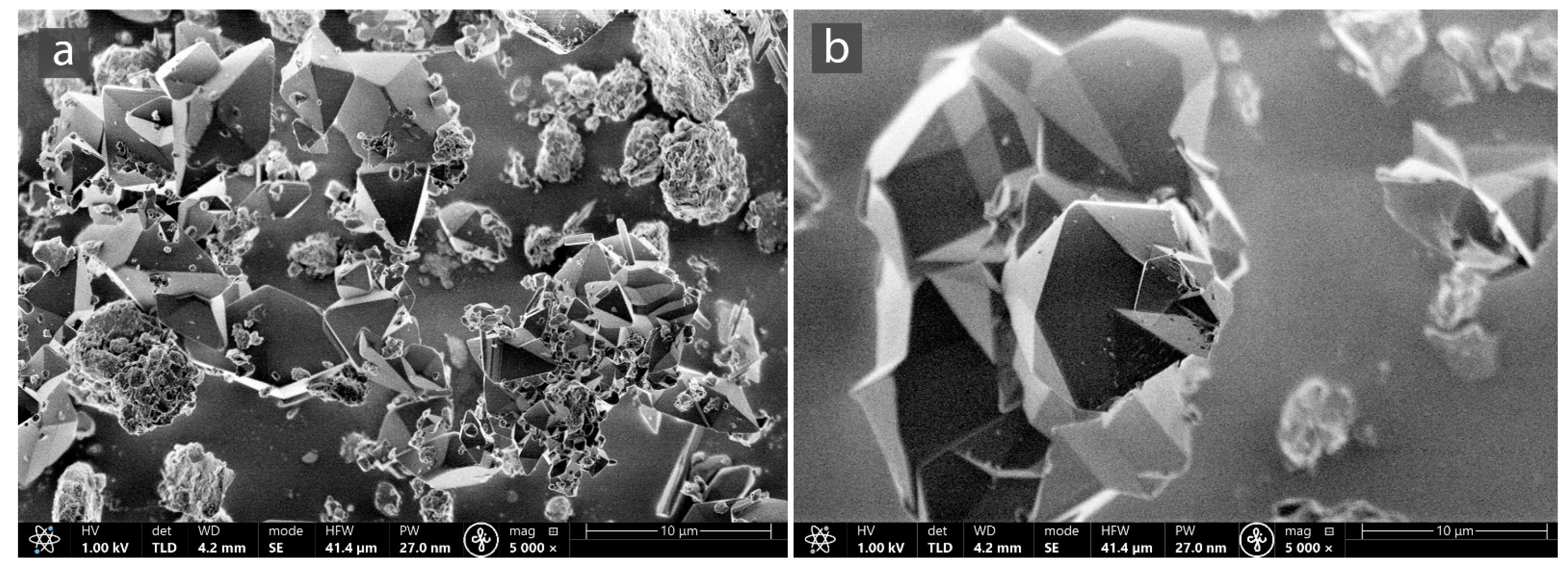
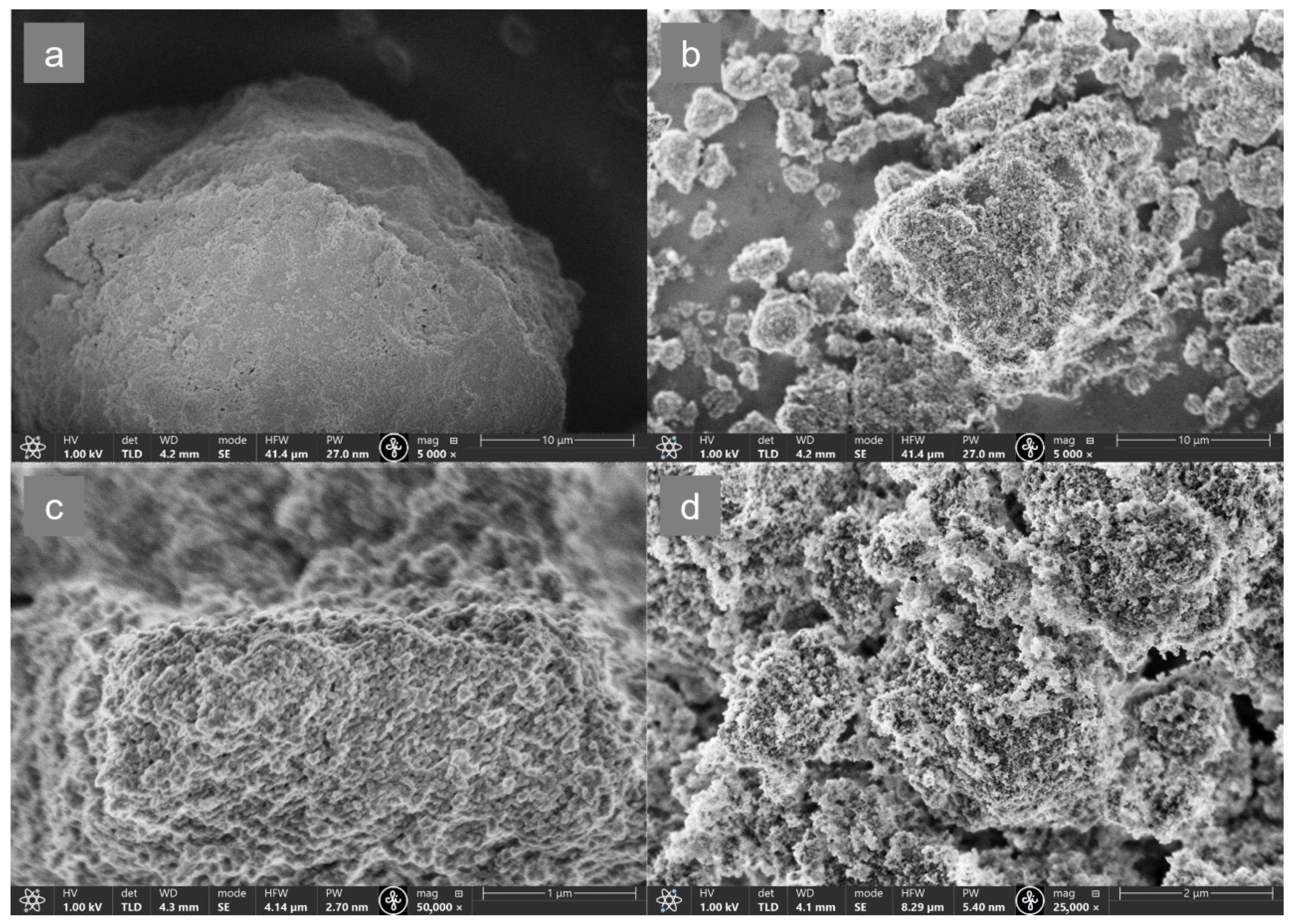
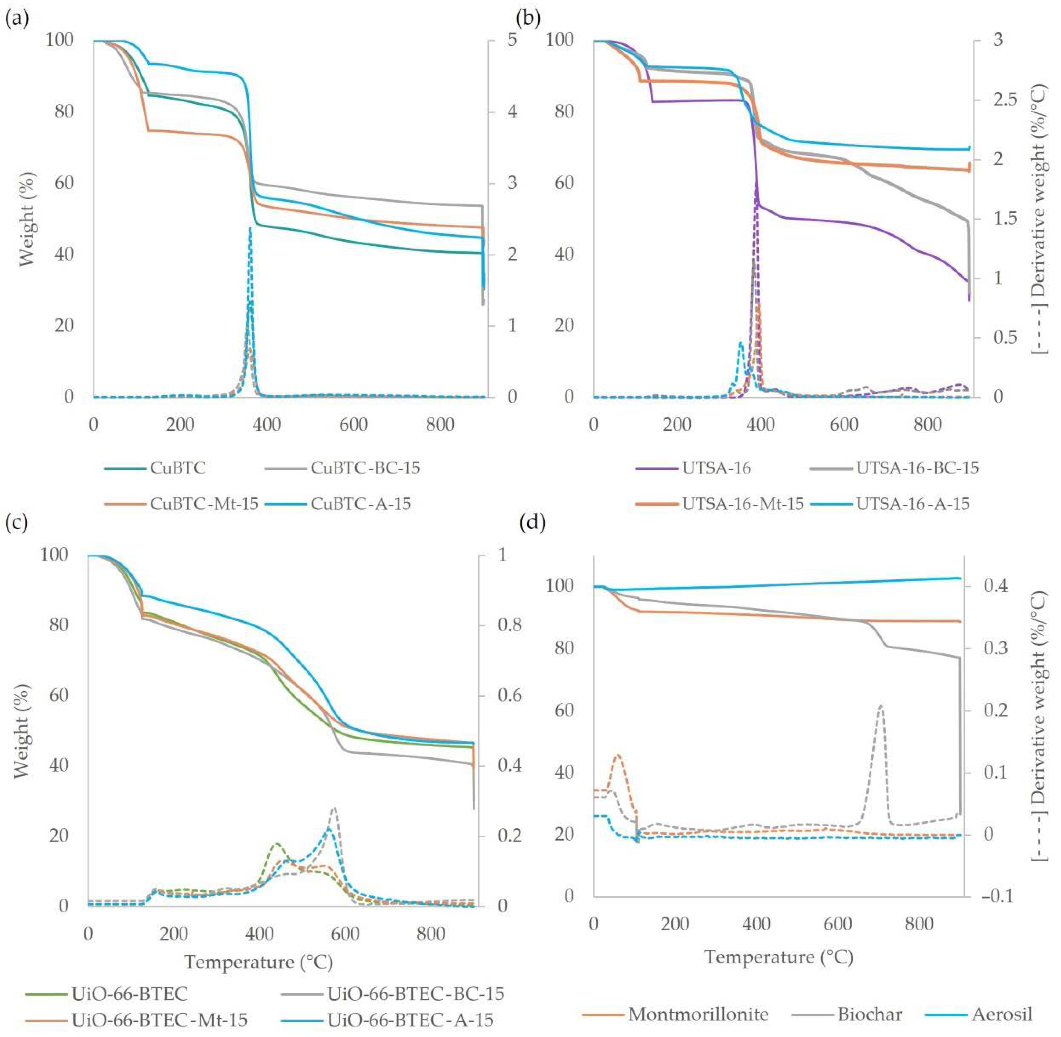
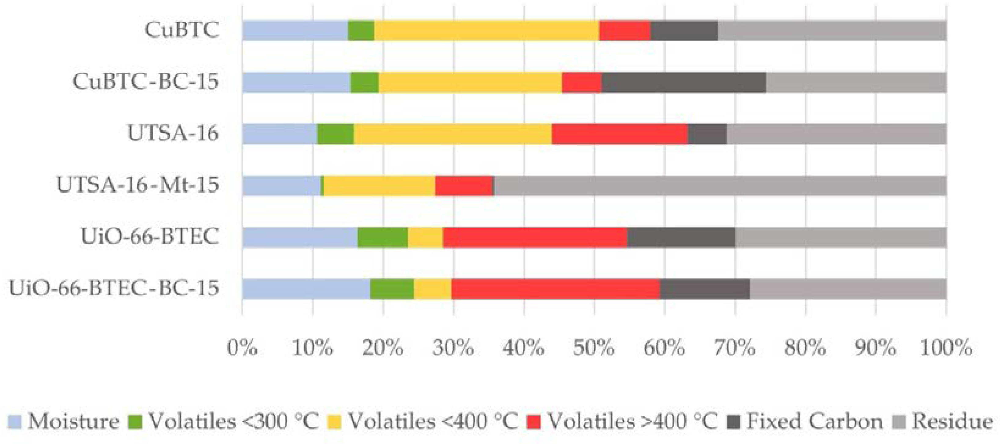
3.1. Characterization of MOF-Composites

Figure 1 shows PXRD patterns of CuBTC-composites and their parent materials (CuBTC, A, Mt, BC). CuBTC obtained in this study has a cubic crystal system and it corresponds to the FM-3m space group. Unit cell parameters of studied materials are shown in Table S1. The patterns simulated from the crystal structure data of pure CuBTC is compatible with the CuBTC obtained in this study. CuBTC-composites still maintained good crystal structure and overall, they were in good agreement when compared with bare CuBTC obtained in this study. The PXRD patterns of CuBTC-composites have the same diffraction peak positions at 2θ = 6.7°, 9.4°, 11.6°, 13.4°, 14.6°, 16.4°, 17.5°, 19.0°, and 20.2° as CuBTC that agrees to that reported in the literature [20]. To clearly illustrate the previously mentioned information, Figure 1 summarizes both the simulated PXRD and the PXRD pattern of CuBTC synthesized in this study, as well as the PXRD patterns of CuBTC-composites containing aerosil (CuBTC-A-15), montmorillonite (CuBTC-Mt-15), and PXRD patterns of CuBTC-composites containing different amounts of biochar (CuBTC-BC-5, CuBTC-BC-15, and CuBTC-BC-30, respectively). In order to illustrate the obtained results more clearly, Figure 1 highlights the part of the PXRD pattern in the 2 theta range from 15° to 50°. PXRD pattern approves the amorphous pattern of aerosil; thus, there were no additional peak signals of CuBTC-A-15 in comparison to bare CuBTC (PXRD signals of CuBTC and CuBTC-A-15 are matching), while the most characteristic diffraction peaks of montmorillonite were observed at 2θ = 8.8°, 17.8°, 19.5°, 20.5°, 23.5°, 26.5°, and 34.9°, which was well matched with the reported spectra [74]. CuBTC-Mt-15 contains pure MOF and the additional diffraction peaks of CuBTC-Mt-15 at 2θ = 8.82°, 19.66°, 20.76°, 26.55°, and 26.77° can be attributed to the presence of Mt. The most intense diffraction peaks of biochar were observed at 2θ = 26.5° and 29.4°, and several smaller peaks were observed, thus indicating the presence of a range of mineral crystals and other inorganic materials. Obtained BC results agree with the reported spectra [75]. The incorporation of BC has not decreased the crystallinity of the framework, as all the locations of diffraction peaks have represented the pure CuBTC structure (matching to the ICDD (International Centre for Diffraction Data) PDF-2-2021) and additional peaks at 2θ = 5.7° and 26.70° of CuBTC-BC-15 and CuBTC-BC-30 were observable, thus confirming the presence of BC. Additional diffraction peak signals were not observed for CuBTC-BC-5 in comparison to bare CuBTC, possibly due to the very low content of the BC, and it can be attributed to high dispersion. Hence, it can be concluded that the incorporation of less than 30 wt% BC preserves the characteristic lattice structure of the CuBTC framework. Moreover, lattice parameters and the volume of the unit cell are shown in Table S1. Mt, BC, or A additives for the CuBTC slightly change the lattice parameters and the volume of the unit cell, where their increase was observed for CuBTC-A-15, CuBTC-Mt-15, and CuBTC-BC-15, but relatively larger biochar additives (as in CuBTC-BC-30) slightly decrease them. Similar to the study by Kamal et al. [76], this could be explained by the distortion of the lattice when the composite material is incorporated into the lattice.
UTSA-16 has a tetragonal crystal system, and it corresponds to the space group I-42d. In this study, obtained spectra matched well with the ones reported in the literature [29] and with the patterns simulated from the crystal structure data of pure UTSA-16. The PXRD patterns (Figure 2) of UTSA-16-Mt-composites have the same diffraction peak positions and overall, they were in good agreement when compared with bare UTSA-16 obtained in this study. The comparison of PXRD patterns of UTSA-16 containing composites (Figure 2) was created following similar principles as CuBTC-composites. Figure 2 summarizes both the simulated PXRD and the PXRD pattern of UTSA-16 synthesized in this study, as well as the PXRD patterns of UTSA-16-composites containing aerosil (UTSA-16-A-15), biochar (UTSA-16-BC-15), and PXRD patterns of UTSA-16-composites containing different amounts of montmorillonite (UTSA-16-Mt-5, UTSA-16-Mt-15, and UTSA-16-Mt-40, respectively). In order to illustrate the obtained results more clearly, Figure 2 highlights the part of the PXRD pattern in the 2 theta range from 15° to 50°. UTSA-16-Mt contains pure UTSA-16 and additional reflexes in UTSA-16-Mt were observed at 2θ = 8.82°, 19.66°, 20.76°, 26.55°, and 26.77° due to the presence of montmorillonite. Besides, it is already mentioned that UTSA-16-Mt-5 also contains citric acid (ICDD Powder Diffraction File Nr: 00-001-0251). In contrast, PXRD patterns of UTSA-16-A-15 and UTSA-16-BC-15 differ from bare UTSA-16. UTSA-16-A-15 contains pure UTSA-16 as well as intermediates cobalt oxide ethanoate (ICDD PDF: 00-022-0244), Tricobalt (II) dihydrate disquarate (ICDD PDF: 01-083-8565), and citric acid (ICDD PDF: 00-001-0251). UTSA-16-BC-15 contains pure UTSA-16 and cobalt oxide ethanoate, and tricobalt (II) dihydrate disquarate.
Figure 3 shows PXRD patterns of UiO-66-BTEC and UiO-66-BTEC-composites. PXRD pattern of UiO-66-BTEC matches with the one reported in the literature [73] and to the patterns simulated from the crystal structure data of pure MOF. Obtained materials have a cubic crystal system and it corresponds to the Pa-3 space group. UiO-66-BTEC-composites have the same diffraction peak position as bare UiO-66-BTEC and they still maintained a good crystal structure. The comparison of PXRD patterns to UiO-66-BTEC containing composites (Figure 3) was created following similar principles as previously mentioned MOF-composites. The UiO-66-BTEC-A-15 signal intensity is weaker and the peaks are wider, possibly due to the presence of amorphous aerosil. UiO-66-BTEC-Mt-15 contains pure UiO-66-BTEC, and the peaks at 2θ = 19.80°, 20.87°, 26.56°, and 34.94° indicate the presence of Mt in the composite, while UiO-66-BTEC-BC-30 contains pure MOF. and the peaks at 2θ = 26.70° indicate the presence of BC in the studied composite as well as ZrCl4 (ICDD PDF: 01-072-1054) at 14.71° and 27.40°. The most intense diffraction peaks of BC (2θ = 26.5° and 29.4°) do not appear in UiO-66-BTEC-BC-15 composites, which is consistent with the situation of UiO-66-BTEC-BC-5. It can be concluded that the reason could be the very low content of BC in the UiO-66-BTEC-BC-5 and UiO-66-BTEC-BC-15 composites.
Changes in lattice parameters and volume of the unit cell (Table S1) are also observed for UTSA-16 and UiO-66-BTEC composites compared to the pure MOFs obtained in this study, but in general, they are small.
Crystalline lattice parameters were determined for the resulting MOF-composites. This was performed based on experimentally obtained powder X-ray diffraction image data taken from the products obtained during the synthesis. Pure crystalline phases CuBTC (XAMDUM06, crystal system—cubic, space group—Fm-3m) [77], UTSA-16 (RAZXIA01, crystal system—tetragonal, space group—I-42d) [78] and UiO-66 (RUBTAK, crystal system—cubic, space group—Pa-3) [79] lattice parameters were used as initial lattice parameters. Using the TOPAS v5.0 program, Pauli’s profile was adjusted.
Figure 4 shows the FTIR spectra of MOFs and MOF-composites obtained in this study. The FTIR pattern of CuBTC was in good agreement with those reported by other authors [22,59,80]. The spectra of all composites were basically similar to that of pristine MOF. For CuBTC and its composites (Figure 4a), the bands around 1647 and 1375 cm−1 were attributed to the asymmetric and symmetric stretching vibrations of C=O, which are present in BTC ligands. The band at 1449 cm−1 corresponded to the C=C skeletal ring vibrations of aromatic carbons. A broad bond at 3423 cm−1 corresponds to hydrogen-bonded -OH stretching and bending vibrations, associated with the adsorbed water on the surface of the samples.
Pure biochar is characterized by a signal at 1449 cm−1, which corresponds to a C=C bond of aromatic carbons and 1050 cm−1 which corresponds to the epoxy stretching. It should be noted that biochar strongly absorbs IR radiation, and thus only signals of relatively rich functionality are observed. The hydroxyl group stretching signals at 3640 cm−1 are relatively weak, while the aromatic C-H signals in a plane and out of the plane bend are more pronounced (at 1041 cm−1 and 873 cm−1). It is important to note that the intensities of these peaks depend on the pyrolysis temperature of the biochar, and their intensity decreases with increasing pyrolysis temperature due to extensive carbonization. The formation of graphite-like structures of the biochar occurs, which shows less intense peaks [81]. Comparing all FTIR spectra of CuBTC composites, it can be concluded that the addition of biochar to the CuBTC-BC-15 composite material does not change the characteristic CuBTC signals, as well as no new signals, are observed. Signals characteristic of montmorillonite were observed in the interval from 3630 to 3420 cm−1, at 1660 cm−1, 1000–1200 cm−1, and 470 cm−1, while those of aerosil were observed at 1100 cm−1, 800 cm−1, and 470 cm−1. The peaks at 468 cm−1, 800 cm−1, and 1045 cm−1 correspond to a band deformation of Si-O-Si, asymmetric stretching of O-Si-O, and stretching vibration of Si-O accordingly, but peaks at 3544 cm−1 and 1660 cm−1 were attributed to the structural -OH stretching and bending vibrations which confirmed the existence of hydroxyl groups, which are present in montmorillonite samples. The intense band observed at 1085 cm−1 for CuBTC-Mt-15 and less intense for CuBTC-A-15 (Figure 4a) represented asymmetric stretching of Si-O-Si [24]. The characteristic bands of CuBTC and montmorillonite, as well as CuBTC and aerosil, can be observed in spectra of CuBTC-Mt and CuBTC-A, clearly indicating the successful incorporation of both CuBTC and Mt or A in the appropriate composites.
The characteristic signals of UTSA-16 (Figure 4b) are observed at 3400 cm−1, in the range from 1670 cm−1 to 1500 cm−1, which characterize the presence of hydroxyl and carboxyl groups, respectively, and are expressed for both pure MOF and all its composites. In addition, the FTIR signal at 1580 cm−1 is characterized by several peaks indicating the involvement of the citrate ligand in the UTSA-16 structure [29]. The FTIR spectral bands in the range 1490–1350 cm−1 can be attributed to carboxyl group fluctuations. The FTIR signals characteristic of UTSA-16 composites coincide with those of pure UTSA-16, but composites containing Mt and A are also characterized by wider and more intense Si-O-Si signals at 1085 cm−1.
The FTIR spectra of UiO-66-BTEC and UiO-66-BTEC-composites are shown in Figure 4c. Characteristic peaks of UiO-66-BTEC are in good agreement with literature data [82,83]. The bands observed at 1700 and 3426 cm−1 from the FTIR spectrum belonged to the -C=O and -OH groups of un-co-ordinated -COOH in UiO-66-BTEC, respectively, indicating the presence of free –COOH groups on the H4BTEC linkers. The band broadening around 3400 cm−1 may result due to the interactions with adsorbed water, and it can be accompanied by the bands at 2640 cm−1 and 2540 cm−1 which are attributed to the hydrogen bonds between facing carboxylic acid groups [84]. The peaks at 1412 cm−1 and 1506 cm−1 are attributed to the vibrations of a benzene ring and the typical peak at 1580 cm−1 corresponds to O-C-O asymmetric stretching vibrations. UiO-66-BTEC-composites exhibit similar characteristic peaks of UiO-66-BTEC. The FTIR spectra of UiO-66-BTEC-Mt-15 and UiO-66-A-15 samples also show broad and strongly characteristic Si-O-Si signals, which indicate the presence of montmorillonite and aerosil in the composites.
The nitrogen adsorption–desorption isotherms were used to characterize the porosity and specific surface area of MOF-composites. According to Israr et al. [71], CuBTC has a characteristic high surface area (SBET 1400 m2/g) and conformity to type-I N2 adsorption–desorption isotherm indicates the nanoporous nature of the materials. According to Zhao et al. [85], the Langmuir surface area of CuBTC is 1387.54 m2/g. The N2 adsorption–desorption isotherms are displayed in Figure 5. CuBTC-A-15 corresponds to the classical type-I N2 adsorption–desorption isotherm of microporous materials. CuBTC-BC-5 shows the type-III isotherm in which the adsorption branch at the range of p/p0 > 0.8 exhibits an enhanced uptake and a small hysteresis loop which means of the generation of some mesopores that can be identified in the Figure 5b. According to the IUPAC classification, pores are classified as micropores when they have pore diameters less than 2 nm, mesopores when the pore diameters are 2–50 nm, and macropores when the pore diameters are greater than 50 nm [26]. In this study, obtained CuBTC-A-15 and CuBTC-BC-5-composites have high Langmuir surface areas of 1716.48 m2/g and 1502.17 m2/g, accordingly. The relatively larger surface area of CuBTC-A-15 can be explained by the formation of new pores at the interface between CuBTC and the aerosil. In contrast, it is considerably lower for CuBTC-BC-15 (620.32 m2/g), owing to the excessive biochar incorporated. The isotherms of UTSA-16-Mt-5 are of type-I, which indicates the presence of microporosity, which is also clearly shown in Figure 5a. According to Masala et al. [29], the Langmuir surface area of UTSA-16 reached 904 m2/g, while in this study the obtained Langmuir surface area of UTSA-16-Mt-15 reached 676.23 m2/g. The N2 adsorption–desorption isotherms of UiO-66-BTEC-composites correspond to the classical type IV H1 isotherm (Figure 5c), according to IUPAC classification, characteristic for mesoporous materials. The isotherm curves measured on both UiO-66-BTEC-BC-15 and UiO-6-BTEC-Mt-15 samples show the hysteresis loops at the P/P0 range from 0.6 to 1.0, while that of UiO-66-BTEC-A-15 is from 0.7 to 1.0, respectively. According to these data, adsorbate is adsorbed on the mesoporous wall by a multilayer adsorption process in the low-pressure range, and it is characterized by the initial part of the isotherm, while the hysteresis loop is associated with capillary condensation taking place in the mesopores. Based on the shape of the hysteresis loop (H1), it can be deduced that the material consists of agglomerates. According to the literature, the Langmuir surface area of UiO-66-BTEC is 470 m2/g and SBET—415 m2/g, accordingly [73]. The Langmuir surface area of UiO-66-BTEC-composites containing biochar or montmorillonite is higher than the one for pristine MOF reported in the literature. Consequently, the Langmuir surface area of UiO-66-BTEC-BC-15 was 567.76 m2/g and 543.40 m2/g for UiO-66-BTEC-Mt-15. In contrast, the same MOF-aerosil composite has smaller values of the Langmuir surface area (330.31 m2/g) in comparison to other UiO-66-BTEC-composites, as well as appropriate pristine MOF. In contrast to CuBTC-composites and UTSA-16-composites, which are predominantly microporous, UiO-66-BTEC-composites are characterized by mesoporosity, as shown in Figure 5d.
SEM and EDX spectra were used to characterize the surface morphology of the MOF-composites. Figure 6 shows SEM images of CuBTC and CuBTC-composite samples. Copper-benzenecarboxylate (CuBTC) is a neutral co-ordination polymer composed of dimeric cupric tetracarboxylate units, where each of two Cu atoms is connected by four bridging carboxylates from BTC and is bound to an axial aqua ligand along the Cu–Cu vector. Furthermore, the aqua ligand can be removed after thermal or chemical treatment, thus leaving the Cu sites co-ordinatively unsaturated and improving copper affinity for binding guest molecules [70]. The structure of CuBTC is characterized by octahedral units with Cu2 dimers at the unit’s six vertices, four ions tetrahedrally inclined as a “plane” for four of the eight triangular faces of the octahedron [86,87]. The octahedral shape of the CuBTC crystals is well seen in Figure 6, where (a) the SEM image of the CuBTC synthesized in this study is shown, while (b–d) show the crystalline CuBTC octahedron to which aerosil, biochar, or montmorillonite are attached, respectively. It is important to note that CuBTC-composites retain their characteristic octahedral crystal shape, but their surface is not smooth and has become much rougher, indicating the incorporation of aerosil, biochar, or montmorillonite in the composite. Moreover, the irregular appearance of some crystals, e.g., the edges and vertices, were much less sharp (Figure 6c,d), which could be attributed to the introduction of biochar or montmorillonite, accordingly. Similar conclusions have been reached by other authors studying CuBTC composite materials with MWCNT [88], CuBTC-GO composites [80,88], and MOF-505@GO composites [59], etc. UTSA-16 is an MOF with empirical formula K2Co3(C6H4O7)2. It has a 3D (3,6) -connected anatase-type structure constituted from tetrahedral Co (II) atoms linked to tetranuclear Co citrate clusters in octahedral geometry, with each one surrounded by four K ions [89]. The SEM image of UTSA-16 (Figure 7a) shows polyhedral crystals, and after modification with montmorillonite (Figure 7b), the UTSA-16-Mt-15-composites keep their original crystal forms, while the montmorillonite particle nonuniformly covers the surface of the UTSA-16 crystals, which is also confirmed by the EDX element-mapping images of this composite (Figure S1). UiO-66-BTEC is characterized by a complex structure that includes hexanuclear Zr6O4(OH)4 metal clusters that are connected by 1,2,4,5-benzenetetracarboxylic acid (BTEC) linkers that form a porous cubic structure. In this structure, a central octahedral cage is surrounded by tetrahedral cages linked by constricted triangular windows [74]. In this study, the obtained UiO-66-BTEC particle surface seems to be large, almost featureless, and contains very small, ill-defined particles (Figure 8a,c), while after modification with aerosil, MOF particles seem to be uniformly covered with aerosil (Figure 8b,d), thus indicating the formation of UiO-66-BTEC-A-15-composites.
A comparison of SEM images of bare MOFs and particles of MOF-composites obtained in this study confirms the formation of MOF-composites.
Energy-dispersive X-ray spectroscopy (EDX or EDS) analysis was used to characterize the element distribution in the MOF-composite. Elemental mapping analysis of CuBTC-BC-15 (Figure S2) indicates that Cu and C are moderately uniformly distributed throughout the CuBTC-BC-15 sample. In some areas, higher concentrations of C are seen, indicating sites with higher concentrations of biochar at CuBTC-BC-15 composite. A similar trend is observed for the distribution of the Co, K, C, Si, and Al elements in the UTSA-16–Mt-15 (Figure S1) and Zr, C, and Si in the UiO-66-BTEC-A-15 (Figure S4) -composite samples, in which nonuniformly distribution was also noticeable. In the UTSA-16-Mt-15 sample, the different distribution of the elements Co, K, C, Si, and Al in the particle reflects the MOF and montmorillonite sites, respectively, but oxygen is evenly distributed throughout the image area since it is an element of both UTSA-16 and clay structures.
Element content in the MOFs and MOF-composites was determined using wet mineralization and consequent analysis with ICP-OES. Moreover, the content of carbon was determined using an element analyzer, and obtained results are shown in Table S2. Changes in the carbon content of MOF-composites correlate well with the amount of biochar added. The content of metallic elements shows the presence of MOF in the composites, while changes in the content of Si and Al indicate the presence of montmorillonite or aerosil in the MOF-composite. The relatively low values of Al and Si can be explained by the stable matrix of the material, which was not cracked during the microwave mineralization process. The content of the elements determined with the element analyzer, ICP-OES, and SEM-EDX is comparable, but there are also differences. For example, the carbon content of CuBTC-BC-15 is 42% (ICP-OES) and 47% (EDX), and the zirconium content of UiO-66-BTEC-A-15 is 18.09% (ICP-OES) and 19.5% (EDX). Larger differences are observed in the content of Si and Al, which can be explained by matrix effects. The results of ICP-OES compared to EDX show higher contents of Cu, K, and Co. It is important to note that the SEM-EDX results are more indicative of the metal ratio of the surface of the samples, and the ICP-OES results quantify the metal ratio of the bulk samples.
Figure 9 presents the TGA and DTG curves. According to the published literature [24], CuBTC is characterized by three weight loss stages, which can be clearly observed for both CuBTC synthesized in this study and all its composites. The first thermal degradation step determines the amount of water moisture (physically adsorbed water molecules) and gas particles that detach around 100 °C. TGA analysis of CuBTC and its composites shows the second weight loss below 200 °C that could be attributed to the removal of the solvent (DMF) that is physically adsorbed and water (chemically bonded water molecules) in the internal pores of the framework. In turn, Ullah et al. [88] suggest that DMF is completely detached when the sample is heated to 250 °C for activation. The breakdown of the framework was observed at the temperature interval from 300 to 370 °C corresponding to the third weight-loss stage. To compare TG data of CuBTC and its composites below 200 °C, it was noticed that CuBTC-A-15 contains the least water while other composites have characteristically higher water content, thus indicating that CuBTC-A-15 is hydrophobic, but CuBTC-Mt-15 and CuBTC-BC-15 are more hydrophilic in comparison to pure CuBTC. CuBTC-BC-composites with different biochar contents in the composite show that a lower BC content in the composite makes the material more hydrophilic, but the thermal stability of MOF-composites with different BC contents is almost equivalent to pure CuBTC (Figure 9 and Figure S4). TG and DTG curves (at a temperature interval from 300 to 400 °C) shows that both CuBTC and CuBTC-composites pose excellent thermal stability. CuBTC-composites show similar thermal behavior as CuBTC, and all of them display a sharp weight loss in TGA curves and intense endothermic–exothermal peaks in DSC curves at the temperature range of 300–370 °C due to the decomposition of BTC ligands, and hence collapse CuBTC crystallites. At this stage, CuBTC lost about 34% of its weight, which is also consistent with the literature [24], while the weight loss of CuBTC-composites is slightly lower (20–33.5%), depending on BC, A, and Mt thermal stability. Consequently, the number of residues of these materials at the end of the analysis also varies. As shown in Figure 5d, aerosil, montmorillonite, and biochar are thermally stable materials. At temperatures up to 100 °C, their weight loss was related to the removal of adsorbed water molecules, but as the temperature rises only weight loss was observed for biochar (at 700 °C), while aerosil and montmorillonite were stable. For montmorillonite at temperatures below 200 °C, weight loss was noticed due to the sorbed moisture and interlayer free water, but between 850 and 1000 °C structural decomposition of solid phase occurs as well as crystallization into other minerals [90].
The characteristic thermal degradation stages of UTSA-16 and its composite material weight loss are observed in the thermogravimetric curves (Figure 9b), where the temperature range from 30 to 130 °C corresponds to the desorption of water, ethanol, and other guest molecules. At temperatures above 350 °C, the sharp weight loss observed in the TG curve demonstrates the collapse of the framework [89]. Pristine UTSA-16 is more hydrophilic compared to its composites. In general, the thermal stability of UTSA-16-composites is similar; however, some differences are observed. The thermal stability of UTSA-16-BC-15 coincides with that of pristine UTSA-16, while DTG curves (Figure 9b) suggest that thermal stability for UTSA-16-Mt-15 was slightly improved. In contrast, thermal degradation of UTSA-16-A-15 happened at lower temperatures compared to pristine MOF. These results can be explained by the results of PXRD, which indicate impurities in the UTSA-16-A-15 sample, which in turn may have affected the thermal stability of this sample. It is worth noting that an added amount of montmorillonite increases the thermal stability of UTSA-16-Mt-composites (Figure S4). As the thermal stability of Mt is higher than that of UTSA-16, the thermal stability of the composite increases with increasing Mt content in the UTSA-16 composite.
For UiO-66-BTEC and its composites, three weight losses are characteristic from which the second and third are hard to evaluate (Figure 9c). The first corresponds to the removal of guest water molecules between 25 and 100 °C, and the second weight loss at temperature intervals from 100 to 400 °C can be attributed to free acid that remained in the pores of the studied material. The third weight loss at 400 °C and 500 °C corresponds to the degradation of the framework to produce ZrO2 [73]. It can be observed that composites containing aerosil takes in slightly less water than raw UiO-66-BTEC or its composites with biochar and montmorillonite. Overall, thermal stability of UiO-66-BTEC and its composite materials is quite similar. However, differences in thermal degradation steps above 400 °C can be observed. UiO-66-BTEC--A-15 and UiO-66-BTEC--BC-15 TG and DTG curves were shifted to the right, thus indicating thermal degradation at higher temperatures than UiO-66-BTEC. Biochar amounts in UiO-66-BTEC-composites suggest that thermal stability is higher only in the cases where the optimal amount of biochar is used, such as in UiO-66-BTEC-BC-15 (Figure 9c and Figure S4).
Overall, the thermal stability of MOF-composites is affected by both the material used in the composite and the amount of composite material added. Obtained results demonstrate that CuBTC and its composites were thermally stable at temperatures as high as 310 °C, UTSA-16, and its composites—up to 350 °C; and UiO-66-BTEC and its composites—up to 400 °C.
Analysis of thermal decomposition product groups (moisture, volatiles <300 °C, <400 °C, >400 °C, fixed carbon, and residue) (Figure 10) shows that MOFs’ thermal degradation occurs in several stages and is influenced by the type of the matrix of the composite adsorbent. UiO-66-BTEC and its composites tend to collapse at higher temperatures than UTSA-16 or CuBTC (Figure S5). CuBTC-BC-15 has slightly less volatile matter than CuBTC, but the fixed carbon amount increases, therefore indicating that organic matter made little improvements with respect to the thermal stability of the composite adsorbent.

3.2. Carbon Dioxide Adsorption onto MOF-Composite Adsorbents

The ability of three different MOFs and their composites to adsorb carbon dioxide was evaluated using the approach of cyclic CO2 adsorption analysis on a thermogravimeter under thermal adsorption conditions, considering the actuality of this process for carbon capture from hot flue gases. The amount of CO2 adsorbed was calculated for each cycle and then the average value was used to compare different materials. The CO2 adsorption capacities of MOF-composites, as well as pristine MOFs, biochar, montmorillonite, and aerosil, are shown in Figure 11. Porous structure, abundant functional groups, high carbon stability, low toxicity, and low cost are properties of biochar that could be a perspective to test its application as a C-containing MOF-composite for CO2 capture and even for other purposes in the future. High stability is a characteristic of aerosils and clays, which can play an important role in the practical application of MOF-composites. As these materials can be obtained relatively easily, and the number of additives studied allows for the maintenance of the characteristic properties of MOF such as a crystalline structure, thermal stability, as well as a relatively high surface area, so it is important to study the CO2 adsorption capacity of these materials. It should be noted that the CO2 adsorption capacities of biochar and montmorillonite reach 0.8 mmol/g and 0.3 mmol/g, respectively, while the CO2 adsorption capacities of MOF-composites containing them are significantly higher. Almost all CuBTC composites show a higher adsorption capacity than CuBTC (2.4 mmol/g), while the CO2 adsorption capacity of UTSA-16 and UiO-66-BTEC composites was lower compared to UTSA-16 (3.9 mmol/g) and UiO-66-BTEC (1.5 mmol/g). CuBTC-composites show an enhanced adsorption ability of CO2 in comparison to CuBTC, except for CuBTC-BC-30. Adsorption capacity increases in the direction CuBTC-Mt-15 < CuBTC-BC-15 < CuBTC-BC-5 < CuBTC-A-15, reaching, accordingly, 2.6 mmol/g, 3.0 mmol/g, 3.7 mmol/g, and 3.7 mmol/g. CuBTC-BC-5 and CuBTC-A-15 composites show the highest adsorption capacity in comparison to all MOF-composites obtained in this study. This is because the biochar and aerosil that were added to CuBTC did not block the pores of CuBTC itself, thus increasing the amount of porosity in the CuBTC-BC-5 and CuBTC-A-15 omposites. Microporosity is a characteristic of CuBTC, but CuBTC-A-15 and CuBTC-BC-5 also show small amounts of mesopores, which may indicate successful composite formation. In addition, micro-mesoporous materials are thought to promote CO2 adsorption. Moreover, the obtained results show that both the used filler additive and its added amount play an important role in the MOF-composite. For example, CuBTC-BC-5 has a relatively high adsorption capacity, while as the BC content increases to 15 wt% and further to 30 wt% (based on parent MOF precursors’ total weight), the adsorption capacity of the MOF-composite decreases significantly. This trend, in turn, can be explained by the excessive number of additives, which reduces the porosity of the material by blocking part of the pores of the MOF-composite. This reduces the number of available adsorption sites and consequently the CO2 adsorption capacity. In this study, the obtained trend is comparable with findings made by other authors; for example, too much graphene oxide in MOF-505 resulted in lower CO2 adsorption capacity [59]. According to the reported literature [21,22,53,91], CO2 adsorption possibly at first occurs on both open Cu cations and cage windows of the MOF, followed by further adsorption governed by the van der Waals forces. However, the electrostatic interaction between Cu cations and CO2 quadrupole is stronger than the van der Waals interaction. Combining MOF, such as CuBTC, and clay or aerosil that contain oxygen-functional groups with the new formed composite material potentially has been complemented with additional mesopores that are favorable for diffusion and mass transfer, possibly due to the attachment of oxygen functional groups of used material to the copper in MOF structure by co-ordination bonds. Biochar can participate in bonding interactions, enhancing the co-ordination bonding with Cu ions, leading to the growth of CuBTC composite, and thus providing improved structures due to the presence of heteroatom-containing functional groups and sp2 aromatic domains in biochar. The adsorption of CO2 on the MOF-composite can be affected not only by the specific surface area but also by the increase in the dispersive forces of the surface due to the presence of the filler material with a dense atomic structure. Moreover, functional groups of filler additives may co-ordinate with Cu2+, resulting in imperfection and defects of crystal surface which could cause more unsaturated Cu2+ metal sites and thus form strong adsorptive sites that may promote CO2 adsorption [59]. In addition, it is possible to improve the thermal and hydrolytic stability of the materials compared to the original MOF; for example, carbon rings from graphene sheets surround the metal center forming a hydrophobic barrier, thus protecting the co-ordination bonds in the MOF [92]. The addition of biochar or clay can have a similar effect, but it should be noted that the amount of the additive is important. The higher its content, the higher the thermal stability, but this may lead to a decrease in porosity and lower CO2 adsorption capacity.
The integration of MOFs and various functional materials with the aim of obtaining new materials that meet specific requirements in terms of functionality, porosity, thermal, magnetic, electrical, and other properties have recently received a lot of attention. Studies on the combination of polymers, metal oxides, carbon nanotubes, various graphene-derived materials, chemically functionalized graphene-derivatives, and MOFs for CO2 adsorption have been frequently published in the literature [11,22,23,49,50,51,52,93,94], but much less attention has been paid to MOF and biochar composites with similar properties such as graphene-derived materials and additional advantages such as easy availability, low cost, and easy synthesis of composites. Liu et al. [22] have studied CO2 adsorption using CuBTC and porous carbon composites and found that ordered-mesoporous carbon and CuBTC composite’s CO2 adsorption capacity is 4.35 mmol/g and 4.49 mmol/g for activated carbon-CuBTC (25 °C, 1 bar). It is worth noting that the mass of carbon was approximately 1% of the total mass of CuBTC precursors. Qian, et al. [95] have studied hierarchical porous carbon monoliths (HCM) with incorporated Cu3(BTC)2 and found that CO2 uptake of HCM-Cu3(BTC)2 composites varies from 2.36 mmol/g to 2.75 mmol/g depending on the number of impregnation steps. Szcznesniak and Choma [54] studied the effect of the amount of GO on the CO2 adsorption capacity of the CuBTC/GO composite and concluded that as the amount of GO in the composite increases (2–10 wt%), its CO2 adsorption capacity decreases (5.12–4.11 mmol/g). In contrast, Shang et al. [58] developed the strategy of CuBTC synthesis and obtained MOF with high CO2 adsorption capacity. Furthermore, its composite with graphene oxide showed a CO2 adsorption capacity 11% higher than that of CuBTC. Doman et al. [56] synthesized and studied HKUST-1-GO composites, containing 0–25% GO and found that the composite obtaining 16 wt% of GO showed the best adsorption performance (8.5 mmol/g, at atmospheric pressure, 0 °C). Ren et al. [23] researched CO2 adsorption on CuBTC-graphene aerogel composite and found that materials adsorption capacity is 3.26 mmol/g. Multiwalled carbon nanotube (MWCNT) incorporation in CuBTC led to an increase in the sorbed amount of CO2 from 1.92 mmol/g for CuBTC to 3.26 mmol/g for CuBTC-MWCNT [88]. An extensive comparison of the adsorption of gases, including CO2, to CuBTC as well as hybrid sorbents of other MOFs and graphene-like layers, is provided by Alfe et al. [94]. Reported results of CO2 adsorption capacity of CuBTC-GO are comparable (2.5–5.1 mmol/g) to the adsorption capacity of CuBTC-BC composites achieved in this study; however, it should be noted that the adsorption capacity is affected by both the amount of additive and the adsorption conditions. Chen et al. [24] have modified CuBTC (HKUST-1) with 0.5–3 wt% (based on the mass of metal precursor) mesoporous silica and found that with the addition of 1%, the CO2 capacity of hybrid material increased by almost 16% in comparison to CuBTC. In our study, the addition of aerosil to CuBTC (CuBTC-A-15) enhances the sorbed CO2 amount by 90.2% in comparison to CuBTC obtained in this study. Moreover, the addition of montmorillonite (CuBTC-Mt-15) increased the sorbed amount of CO2 by 27%, and the addition of the same amount of biochar (CuBTC-BC-15) increased the sorbed CO2 amount by 34% in comparison to pristine CuBTC. For comparison, Wan et al. [96] have studied CuBTC and attapulgite (ATP, natural hydrous magnesium–aluminum silicate mineral (HKUST-1/ATP)) composite CO2 adsorption abilities and found that in HKUST-1/ATP the CO2 adsorption capacity (127.88 cm3/g) was 11.27% more than that of HKUST-1.
Compared to CuBTC-composites, UTSA-16-composites have been less studied, with more focus on UTSA-16-coated monoliths [97,98,99]. According to the literature [29], CO2 adsorption on UTSA-16 can occur in three adsorption sites—two of them are related to K+ cations located inside the UTSA-16 channels, and weaker interaction with the organic linkers in the MOF. Relatively higher CO2 adsorption ability is achieved for the UTSA-16-Mt-5 sample, while increasing the content of montmorillonite in UTSA-16-Mt-composites decreases their adsorption capacity. In this case, the additive of montmorillonite may be too large and completely or partially block the adsorption sites of UTSA-16, thus reducing the amount adsorbed. However, the adsorbed amount of CO2 using UTSA-16-Mt-5 reaches 2.82 mmol/g, and obtained results are comparable with results reported by other studies using MOF-clay composites. For example, Thakkar et al. [92] have studied 3D printed UTSA-16, which contains about 10 wt% of bentonite. Lawson et al. [98] have studied UTSA-16 growth within 3D printed Co-kaolin monolith and found that such material can uptake 3.1 mmol/g CO2 at 25 °C, 1 bar. Rezaei et al. [99] have found that the maximum CO2 adsorption capacity for UTSA-16 synthesized by a solvothermal method was 4.0 mmol/g, whereas the UTSA-16 coated monolith reached a CO2 capacity of 1.1 mmol/g at 1 bar and 298 K. Similar results of 4.0–4.2 mmol/g for UTSA-16 adsorption abilities were obtained by Masala et al. [28] and Gaikwad et al. [100]. However, to improve the CO2/CH4 selectivity of UTSA-16, Shen et al. [30] studied UTSA-16-GO composites with different GO contents, although the best of the UTSA-16-GO composites studied had slightly lower CO2 adsorption performance (81 cm3/g at 296 K, 1 atm) than the pristine UTSA-16 (96 cm3/g), and obtained composite showed improved selectivity. Although the CO2 adsorption values of pristine UTSA-16 are in agreement with those reported in the literature, the adsorption capacity of UTSA-16 composites may be reduced not only by the addition of BC, A, or Mt but also by impurities from the synthesis. In the future, ultrasonic or microwave approaches could be used to overcome these shortcomings in the synthesis.
According to the literature [101], CO2 uptake for UiO-66-BTEC reached 1.821 mmol/g (298 K, 1 bar) and it is comparable to the adsorption capacity of UiO-66-BTEC obtained in this study, which reaches 1.433 mmol/g, respectively. UiO-66-BTEC-composites have relatively similar adsorption capacities ranging from 0.95 mmol/g for UiO-66-BTEC-BC-5 to 1.29 mmol/g for UiO-66-BTEC-BC-15. The addition of aerosil and montmorillonite (15 wt% of parent MOF precursors’ total weight) provides similar MOF-composite adsorption abilities of 1.02 mmol/g and 1.11 mmol/g, accordingly. Physical CO2 adsorption on UiO-66-BTEC is provided by the presence of free and accessible -COOH groups, as well as surface properties, which have an impact on materials’ adsorption abilities since the specific surface area of UiO-66-BTEC-BC-15 (567 m2/g) is higher than that of UiO-66-BTEC-composites containing montmorillonite or aerosil (543 m2/g and 330 m2/g accordingly). UiO-66-BTEC-composites have a higher adsorption capacity than biochar, aerosil, and montmorillonite, but the addition of additives did not lead to a significant increase in capacity compared to pristine MOF. Considering both the UiO-66-BTEC content in each of the composites (ranging from 77 to 95%, respectively) and the CO2 adsorption capacity of pure MOF, it can be concluded that the CO2 adsorption capacity of pristine MOF is constant or very minimally increased.
The CO2 adsorption results of the MOF-composites obtained in this study, as well as the MOF surface areas, are comparable to the results obtained in other studies, which are summarized in Table 1. However, if most of the studies were performed at an ambient temperature, our aim was to study CO2 adsorption at elevated temperatures, which is common if the aim is to capture carbon from flue gases. Table 1 includes CuBTC, UTSA-16, and UiO-66-BTEC composites and pure MOFs studied by other authors, as well as an example of a benchmark adsorbent—Zeolite 13X. Comparing the obtained results, it can be seen that the CO2 adsorption capacity and surface area values of the sorbents synthesized in this study are lower compared to some data from Table 1. However, it is important to note that surface area, pore volume, crystal defects, and adsorption conditions are important when comparing adsorption capacity. This is also evidenced by differences in both surface area and adsorption capacity when comparing a single material, such as CuBTC or HKUST-1, studied by different groups of authors. One of the reasons for the different surface areas of MOF and their composites, and thus the CO2 adsorption capacities, is the differences in the materials’ synthesis procedures. For example, the solvent used, the modulator, and the synthesis method (sonochemical, solvothermal, microwave assisted) play an important role in the overall morphology, surface area, and sequential CO2 adsorption capacity of the resulting material. Moreover, some of the composites contain nitrogen-containing functional groups (for example, aminoclays (AC), urea (U)), that also may enhance the adsorption capacity of the adsorbent due to the high affinity between CO2 and amine species.
Most CuBTC-composites, as well as UTSA-16-Mt-5, obtained in this study show higher CO2 adsorption capacity than Zeolite 13X [102]. However, when comparing the adsorption performance with zeolites, it should be noted that the range of zeolites used to capture CO2 is wide. A recent review by Zagho [103] summarizes advances in CO2 separation using zeolite and zeolite-like materials (modified zeolites) as CO2 adsorbents. The CO2 adsorption capacities of pristine zeolites compiled in the study by Zagho [103] depending on the type of zeolite (β, 13X, 4A, Y, 5A, NaX, SSZ-13, clinoptilolite) and the adsorption conditions, range from 0.36 mmol/g (13X, 1 atm, 75 °C) [104] to 6.27 mmol/g (binder free 13X, 298 K, 1 bar) [105].
Like zeolites, a wide range of carbonaceous materials, including activated carbon from various sources, is used as a CO2 adsorbent. The adsorption capacity of the MOF-composites obtained in this study is similar to the adsorption capacity of activated carbon summarized in the review of Pardakhti [106]. It should be noted that the adsorption capacity of activated carbon depends on the precursor used, the type of activation, and the CO2 adsorption conditions. For example, the CO2 adsorption capacity of activated carbon from biomass waste (using physical activation under CO2) reaches 2–3 mmol/g (1 bar, 25 °C) [107]. Graphene oxide, including reduced graphene oxide and its various modifications, is a group of materials with a wide range of applications, especially for CO2 adsorption. In order to improve the properties of this material, the possibilities of its functionalization with various heteroatoms (Si, S, N, O) containing compounds have been studied, as a result of which materials with increased porosity and surface area are obtained [108]. The surface areas (BET) of reduced graphene oxides and modified graphene oxides studied by Politakos [108] are in the range of 70–351 m2/g, and their CO2 adsorption capacities are in the range of 0.47–1.67 mmol/g (25 °C, atmospheric pressure). Thus, it can be concluded that raw biochar is an equivalent CO2 adsorbent, as it shows similar CO2 adsorption capacities, which can be increased by forming composites with, for example, CuBTC or UiO-66-BTEC.
Table 1. MOF and MOF-composite CO2 adsorption capacities.
MOF-CompositeSurface Area (BET), m2/gCO2 AdsorptionCO2 Adsorption ConditionsReference
HCM-Cu3(BTC)2-12702.36 mmol/g25 °C[95]
CuBTC-OMC12884.35 mmol/g25 °C, 1 bar[22]
CuBTC-AC13684.49 mmol/g25 °C, 1 bar[22]
CuBTC-NC13644.51 mmol/g25 °C, 1 bar[22]
CuBTC/GA10483.26 mmol/g298 K, 1 bar[23]
MWCNTs@CuBTC7273.26 mmol/gambient conditions[88]
HS-11745108.0 cm3/g25 °C, 1 bar[24]
CuBTC17605.33 mmol/g25 °C, 1 bar[54]
CuBTC/GO218205.12 mmol/g25 °C, 1 bar[54]
CuBTC/GO515204.79 mmol/g25 °C, 1 bar[54]
CuBTC/GO1013804.11 mmol/g25 °C, 1 bar[54]
CuBTC8922.46 mmol/g295 K, 0.12 MPa[45]
CuBTC/GO10103.09 mmol/g295 K, 0.12 MPa[45]
CuBTC/GO-U313674.78 mmol/g295 K, 0.12 MPa[45]
CuBTC15943.06 mmol/g25 °C, 100 kPa[55]
CuBTC@MWCNT11503.4 mmol/g25 °C, 100 kPa[55]
HKUST-11322114.92 cm3/g298 K[80]
HKUST-1/ATP1158127.88 cm3/g298 K[80]
CuBTC15808.02 mmol/g273 K, 1 bar[58]
CuBTC@1%GO17728.90 mmol/g273 K, 1 bar[58]
CuBTC-AC-213815.35 mmol/g298 K, 1 bar[25]
CuBTC-AC-213818.1 mmol/g273 K, 1 bar[25]
Zeolite 13X570210 mg/gambient temperatures, 1 bar[109]
Zeolite 13X6161.77 mmol/g293 K, 1 bar[102]
UTSA-16628189 mg/gambient temperatures, 1 bar[109]
UTSA-16@Co-kaolin6203.1 mmol/g25 °C, 1 bar[82]
UTSA-16/carbon composites2112.0 mmol/groom temp., 1 bar[110]
UTSA-16(Co)-cordierite monolith2231.1 mmol/g298 K, 1 bar[99]
UTSA-16 monolith containing bentonite5683.0 mmol/g25 °C, 1.1 bar[92]
UTSA-167273.5 mmol/g25 °C, 1.1 bar[92]
UiO-66-BTEC568 (Langmuir surf. area)1.05 mmol/g303 K, 0.99 bar[34]
HKUST-1@GO-215508.5 mmol/g0 °C, atmospheric pressure[56]
CuBTC13056.39 mmol/g273 K, 1 atm[44]
CG-3 (CuBTC-GO-3)14707.94 mmol/g273 K, 1 atm[44]
CG-9 (CuBTC-GO-9)15328.26 mmol/g273 K, 1 atm[44]
CG-15 (CuBTC-GO-15)5002.97 mmol/g273 K, 1 atm[44]
Cu3(BTC)29332.77 mmol/g298 K, 1 bar[46]
Cu3(BTC)2/GO-l8983.13 mmol/g298 K, 1 bar[46]
Cu3(BTC)2/GO-m8373.37 mmol/g298 K, 1 bar[46]
Cu3(BTC)2/GO-h7432.66 mmol/g298 K, 1 bar[46]
Cu3(BTC)21587295 mg/g298 K, 18 bar[47]
CNT@Cu3(BTC)21458595 mg/g298 K, 18 bar[47]
HKUST-14341.59 mmol/g25 °C, 1 bar[111]
HKUST-1/GO3690.98 mmol/g25 °C, 1 bar[111]
HKUST-114107.92 mmol/g196 K, 1 bar[112]
5wt% SWCNT@HKUST-117148.75 mmol/g196 K, 1 bar[112]
HKUST-11379.873.55 mmol/g25 °C, 1 bar[113]
HKUST-1@GO1096.462.53 mmol/g25 °C, 1 bar[113]
Overall, it can be concluded that the most promising of all sorbents are CuBTC-A-15 and CuBTC-BC-5, which show the highest CO2 adsorption capacity, respectively. Although other composites do not show significantly increased CO2 adsorption capacity, it is important to consider other properties to evaluate their performance, such as montmorillonite additives increasing the thermal stability of the composites. The percentage synthesis results of the composites are higher in all cases than the pure MOFs. As one of the main disadvantages of MOFs is their powdery nature, the obtained results can serve for further improvement of the material, increasing the possibilities of practical applicability. In addition, the filler additives used are readily available, inexpensive materials.
The reusability of the adsorbent is an important factor for the practical application performance of the adsorbent; therefore, the cyclic adsorption performances were investigated. The amount of CO2 adsorbed was calculated for each adsorption cycle and the results show that it decreases from 2.05 mmol/g to 1.92 mmol/g from the first to the sixth cycle. For CuBTC-BC-5, it decreases from 3.7 to 3.4 mmol/g, while an increase in adsorption from 3.7 to 3.9 mmol/g is observed for CuBTC-A-15. To test the stability of the results, experiments were performed with 20 cycle adsorptions, the results of which confirmed the previously observed trends (change does not exceed 3%). The increase in adsorption can be explained by the activation of new adsorption sites after the first ones are occupied. Comparing the results of cyclic CO2 adsorption of CuBTC-BC-5 and CuBTC-A-15 with the adsorption results of these MOF-composite parent materials (Figure 12a,b), it can be concluded that the reusability of the obtained composites is affected by the synergistic effect of both CuBTC and composite parent materials because the adsorption capacity of biochar and aerosil remains almost stable (0.3% decrease for both montmorillonite and biochar) over a six-cycle interval.
The adsorption of CO2 on UTSA-16 and its composites can be considered stable. Carbon dioxide adsorption and desorption cycles for UTSA-16 show adsorption reduction by 0.9% after five adsorption cycles (Figure 12c). Adsorption stability seems to slightly increase with UTSA-16 composite materials as their ability for CO2 uptake after five cycles reduces by only around 0.4% (Figure S6b).
In general, UiO-66-BTEC composites show similar adsorption stability. UiO-66-BTEC adsorption stability decreased by 1.35% after five adsorption–desorption cycles (Figure 12). The most stable of UiO-66-BTEC-composites was UiO-66-BTEC-BC-15, as its adsorption capacity was reduced only by 0.51% (Figure S6c). The adsorption capacity for UiO-66-BTEC-A-15 decreased by 1.38%.

3.3. Future Work and Perspectives

The moisture stability of original MOFs, as well as those of filler materials, is known from the literature, but these types of properties of CuBTC, UTSA-16, and UiO-66-BTEC composites will be studied in detail in the future and the next report will be prepared. However, pretests have been performed by exposing the materials to water for 2 h and taking up PXRD after filtration and drying. The obtained results showed that CuBTC-A-15 is characterized by higher signal intensities compared to untreated CuBTC. Compared to the sample obtained before treatment with water, the appearance of small, new signals, which may be related to the onset of dissolution of the material, is noticed. However, the intensity of these signals in CuBTC-A-15 is lower than in untreated CuBTC, which may indicate that the aerosil additive increases the stability of the material. However, additional experiments are planned to fully demonstrate this. Based on preliminary tests, it can be concluded that UTSA-16-Mt-5 and UTSA-16 have a similar moisture resistance, while UiO-66-BTEC-BC-15 and UiO-66-BTEC are stable even after 2 h in water. It is clearly visible in their PXRD (Figure S7) pattern that fully coincides with the signals from the untreated MOF and MOF-composite.
The selectivity of original MOFs as well as those of filler materials is known from the literature and is high in respect to N2 and CH4, but these types of properties of CuBTC, UTSA-16, and UiO-66-BTEC composites will be studied in detail in the future. The properties of both MOFs and filler additives and their synergistic effect must be taken into account when assessing the selectivity of materials. High selectivity has been highlighted in the literature as one of the advantages of UTSA-16 and UiO-66-BTEC. Thus, it can be speculated that the composites of these MOFs will also have similar properties, as shown by studies using similar additives such as clays and GO. Moreover, studies by several authors on CuBTC composites with GO (including even with 5% GO additive) show that the selectivity (CO2/CH4, CO2/N2) of the obtained composite is significantly higher than that of the parent materials [52].

4. Conclusions

In this study, new MOF-composites containing biochar, clay, or aerosil were obtained by the in situ method. The composites are based on known MOFs such as CuBTC, UTSA-16, and UiO-66-BTEC. However, their application with the used carriers is novel. The obtained MOF-composites are characterized by both the properties of the corresponding MOF. For example, its crystalline structure is preserved, the characteristic crystal form is identifiable, and so are the characteristics indicating the presence of additives (changes in surface area, thermal stability). CuBTC-biochar and CuBTC-aerosil composites are the most promising for CO2 adsorption. In our study, the addition of aerosil to CuBTC (CuBTC-A-15) enhances the adsorbed CO2 amount by 82% and the addition of biochar (CuBTC-BC-5) increased the amount of adsorbed CO2 by 75.5% in comparison to pristine CuBTC obtained in this study. Moreover, the addition of montmorillonite (CuBTC-Mt-15) increased the adsorbed amount of CO2 by 27% in comparison to pristine CuBTC.
In general, comparing the composites of three different MOFs (CuBTC, UTSA-16, and UiO-66-BTEC), it can be concluded that CuBTC composites can be considered as the most promising, as both aerosil, biochar, and montmorillonite containing CuBTC-composites show higher CO2 adsorption capacity compared to pristine MOF. Unlike UTSA-16 composites, UiO-66-BTEC composites show smaller differences in cross-CO2 adsorption capacities as well as smaller differences compared to pristine MOF. In contrast, the type and amount of additive used in UTSA-16 composites has a more significant effect on the CO2 adsorption capacity of the composite.
Although the CO2 adsorption capacity of UTSA-16 composites and UiO-66-BTEC composites is lower compared to pure MOFs, their benefits could be: relatively easy synthesis of composites, widespread use of additives, and inexpensive. Moreover, the yield (%) of all MOF-composites is higher than that of pure MOFs, which in turn can be important in upscaling the production process. For example, the presence of montmorillonite provides a higher thermal stability of composite materials. The powdered nature of MOFs is also one of the shortcomings that could be addressed in the future, given the results of MOF-composite studies in this study, such as the development of 3D printed MOFs.
The adsorption capacities of MOF and MOF-composites obtained in this study are comparable with the results published by other authors. However, it is important to note that surface area, pore volume, crystal defects and adsorption conditions are important when comparing adsorption capacity. This is also evidenced by differences in both surface area and adsorption capacity when comparing a single material, such as CuBTC or HKUST-1, studied by different groups of authors. One of the reasons for the different surface areas of MOF and their composites, and thus the CO2 adsorption capacities, is the differences in the materials’ synthesis procedures. For example, the solvent used, the modulator, as well as the synthesis method (sonochemical, solvothermal, microwave assisted), play an important role in the overall morphology, surface area, and sequential CO2 adsorption capacity of the resulting material.

Supplementary Materials

The following supporting information can be downloaded at: www.mdpi.com/article/10.3390/en15093473/s1. Figure S1: EDS element mapping image of UTSA-16-Mt-15; Figure S2: EDS element mapping image of CuBTC-BC-15; Figure S3: EDS element mapping image of UiO-66-BTEC-A-15; Figure S4: Thermogravimetric analysis (TGA) of MOF-composites: (a) CuBTC-composites; (b) UTSA-16-composites; (c) UiO-66-BTEC-composites; Figure S5: Thermal degradation matrix of MOF-composites; Figure S6: CO2 adsorption and desorption cycles of MOF-composites: (a) CuBTC-composites; (b) UTSA-16-composites; (c) UiO-66-BTEC-composites; Figure S7: PXRD spectra of CuBTC (H2O) after exposure to water, raw CuBTC and CuBTC-composite containing aerosil (CuBTC-A-15 (H2O)) after exposure to water. PXRD spectra of UTSA-16 (H2O) after exposure to water, raw UTSA-16 and UTSA-16-composite containing montmorillonite (UTSA-16-Mt-5 (H2O)) after exposure to water. PXRD spectra of UiO-66-BTEC (H2O) after exposure to water, raw UiO-66-BTEC and UiO-66-BTEC-composite containing biochar (CuBTC-BC-15 (H2O)) after exposure to water; Table S1: Characterization of the studied MOFs and their composites; Table S2. Content of the elements in MOFs and their composites.

Author Contributions

Conceptualization, M.K., methodology, M.K., L.A.-B., V.O., K.S., E.V., L.A., and L.D.; software, K.S., and V.O.; validation, L.D., investigation, L.A.-B., V.O., and K.S.; resources, M.K., L.A.-B.; data curation, M.K., L.A.-B.; writing—original draft preparation L.A.-B.; writing—review and editing, M.K., L.A.-B., V.O., K.S., E.V., and L.A.; visualization, L.A.-B., V.O., and E.V.; supervision, M.K.; project administration, M.K.; funding acquisition, M.K. All authors have read and agreed to the published version of the manuscript.

Funding

This research was funded by the European Regional Development Fund project “Innovation of the waste-to-energy concept for the low carbon economy: development of novel carbon capture technology for thermochemical processing of municipal solid waste (carbon capture and storage from waste—CCSW)”, grant number 1.1.1.1/19/A/013.

Institutional Review Board Statement

Not applicable.

Informed Consent Statement

Not applicable.

Data Availability Statement

Not applicable.

Conflicts of Interest

The authors declare no conflict of interest. The funders had no role in the design of the study; in the collection, analyses, or interpretation of data; in the writing of the manuscript; or in the decision to publish the results.

References

  1. Al-Ghussain, L. Global warming: Review on driving forces and mitigation. Environ. Prog. Sustain. Energy 2019, 38, 13–21. [Google Scholar] [CrossRef] [Green Version]
  2. Fawzy, S.; Osman, A.I.; Doran, J.; Rooney, D.W. Strategies for mitigation of climate change: A review. Environ. Chem. Lett. 2020, 18, 2069–2094. [Google Scholar] [CrossRef]
  3. Green Deal. Striving to the First Climate-Neutral Continent. 2021. Available online: https://ec.europa.eu/info/strategy/priorities-2019-2024/european-green-deal_en (accessed on 24 February 2022.).
  4. Alami, A.H.; Hawili, A.A.; Tawalbeh, M.; Hasan, R.; Al Mahmoud, L.; Chibib, S.; Aokal, K.; Mahmood, A.; Rattanapanya, P. Materials and logistics for carbon dioxide capture, storage and utilization. Sci. Total Environ. 2020, 717, 137221. [Google Scholar] [CrossRef] [PubMed]
  5. Boot-Handford, M.E.; Abanades, J.C.; Anthony, E.J.; Blunt, M.J.; Brandani, S.; Mac Dowell, N.; Fernandez, J.R.; Ferrari, M.C.; Gross, R.; Hallett, J.P.; et al. Carbon capture and storage update. Energy Environ. Sci. 2014, 7, 130–189. [Google Scholar] [CrossRef]
  6. Sabri, M.A.; Al Jitan, S.; Bahamon, D.; Vega, L.F.; Palmisano, G. Current and future perspectives on catalytic-based integrated carbon capture and utilization. Sci. Total Environ. 2021, 790, 148081. [Google Scholar] [CrossRef]
  7. Pant, D.; Nadda, A.K.; Pant, K.K.; Agarwal, A.K. Advances in Carbon Capture and Utilization. In Advances in Carbon Capture and Utilization; Springer: Singapore, 2021; pp. 3–7. [Google Scholar]
  8. Pellegrini, L.A.; De Guido, G.; Ingrosso, S. Thermodynamic Framework for Cryogenic Carbon Capture. In Computer Aided Chemical Engineering; Elsevier: Amsterdam, The Netherlands, 2020; Volume 48, pp. 475–480. [Google Scholar] [CrossRef]
  9. Shah, S.; Shah, M.; Shah, A.; Shah, M. Evolution in the membrane-based materials and comprehensive review on carbon capture and storage in industries. Emerg. Mater. 2020, 3, 33–44. [Google Scholar] [CrossRef]
  10. Zhang, X.; Song, Z.; Gani, R.; Zhou, T. Comparative economic analysis of physical, chemical, and hybrid absorption processes for carbon capture. Ind. Eng. Chem. Res. 2020, 59, 2005–2012. [Google Scholar] [CrossRef]
  11. Ghanbari, T.; Abnisa, F.; Daud, W.M.A.W. A review on production of metal organic frameworks (MOF) for CO2 adsorption. Sci. Total Environ. 2020, 707, 135090. [Google Scholar] [CrossRef]
  12. Sharma, H.; Dhir, A. Capture of carbon dioxide using solid carbonaceous and non-carbonaceous adsorbents: A review. Environ. Chem. Lett. 2021, 19, 851–873. [Google Scholar] [CrossRef]
  13. Siegelman, R.L.; Kim, E.J.; Long, J.R. Porous materials for carbon dioxide separations. Nat. Mater. 2021, 20, 1060–1072. [Google Scholar] [CrossRef]
  14. Osman, A.I.; Hefny, M.; Abdel Maksoud, M.I.A.; Elgarahy, A.M.; Rooney, D.W. Recent advances in carbon capture storage and utilisation technologies: A review. Environ. Chem. Lett. 2021, 19, 797–849. [Google Scholar] [CrossRef]
  15. Piscopo, C.G.; Loebbecke, S. Strategies to enhance carbon dioxide capture in metal-organic frameworks. ChemPlusChem 2020, 85, 538–547. [Google Scholar] [CrossRef] [PubMed]
  16. Luedtke, Z.; Aro, M.; Sun, Z.; Toan, S. Carbon Capture Materials and Technologies: A Review. Curr. Res. Mater. Chem. 2020, 3, 108. [Google Scholar] [CrossRef]
  17. Aniruddha, R.; Sreedhar, I.; Reddy, B.M. MOFs in carbon capture-past, present and future. J. CO2 Util. 2020, 42, 101297. [Google Scholar] [CrossRef]
  18. Younas, M.; Rezakazemi, M.; Daud, M.; Wazir, M.B.; Ahmad, S.; Ullah, N.; Ramakrishna, S. Recent progress and remaining challenges in post-combustion CO2 capture using metal-organic frameworks (MOFs). Prog. Energy Combust. 2020, 80, 100849. [Google Scholar] [CrossRef]
  19. Peedikakkal, A.M.; Aljundi, I.H. Mixed-metal Cu-BTC metal−organic frameworks as a strong adsorbent for molecular hydrogen at low temperatures. ACS Omega 2020, 5, 28493–28499. [Google Scholar] [CrossRef]
  20. Al-Janabi, N.; Deng, H.; Borges, J.; Liu, X.; Garforth, A.; Siperstein, F.; Fan, X. A facile post-synthetic modification method to improve hydrothermal stability and CO2 selectivity of CuBTC metal-organic framework. Ind. Eng. Chem. Res. 2016, 55, 7941–7949. [Google Scholar] [CrossRef] [Green Version]
  21. Zhou, C.; Cao, L.; Wei, S.; Zhang, X.; Chen, L. A first principles study of gas adsorption on charged Cu-BTC. Comput. Theor. Chem. 2011, 976, 153–160. [Google Scholar] [CrossRef]
  22. Liu, Y.; Ghimire, P.; Jaroniec, M. Copper benzene-1,3,5-tricarboxylate (Cu-BTC) metal-organic framework (MOF) and porous carbon composites as efficient carbon dioxide adsorbents. J. Colloid Interface Sci. 2019, 535, 122–132. [Google Scholar] [CrossRef]
  23. Ren, W.; Wei, Z.; Xia, X.; Hong, Z.; Li, S. CO2 adsorption performance of CuBTC/graphene aerogel composites. J. Nanopart. Res. 2020, 22, 191. [Google Scholar] [CrossRef]
  24. Chen, C.; Li, B.; Zhou, L.; Xia, Z.; Feng, N.; Ding, J.; Wang, L.; Wan, H.; Guan, G. Synthesis of hierarchically structured hybrid materials by controlled self-assembly of Metal−Organic Framework with mesoporous silica for CO2 adsorption. ACS Appl. Mater. Interfaces 2017, 9, 23060–23071. [Google Scholar] [CrossRef] [PubMed]
  25. Chakraborty, A.; Achari, A.; Eswaramoorthy, M.; Maji, T.K. MOF-aminoclay composites for superior CO2 capture, separation and enhanced catalytic activity in chemical fixation of CO2. Chem. Commun. 2016, 52, 11378–11381. [Google Scholar] [CrossRef] [PubMed]
  26. Abdoli, Y.; Razavian, M.; Fatemi, S. Bimetallic Ni–Co-based metal–organic framework: An open metal site adsorbent for enhancing CO2 capture. Appl. Organometal. Chem. 2019, 33, e5004. [Google Scholar] [CrossRef]
  27. Peh, S.B.; Xi, S.; Karmakar, A.; Yeo, J.Y.; Wang, Y.; Zhao, D. Accelerated formation kinetics of a multicomponent metal−organic framework derived from preferential site occupancy. Inorg. Chem. 2020, 59, 9350–9355. [Google Scholar] [CrossRef] [PubMed]
  28. Masasla, A.; Grifasi, F.; Atzori, C.; Vitillo, J.G.; Mino, L.; Bonino, F.; Chierotti, R.; Bordiga, S. CO2 adsorption sites in UTSA-16: Multitechnique approach. J. Phys. Chem. C 2016, 120, 12068–12074. [Google Scholar] [CrossRef] [Green Version]
  29. Masala, A.; Vitillo, J.G.; Bonino, F.; Manzoli, M.; Grabde, C.A.; Bordiga, S. New insights into UTSA-16. Phys. Chem. Chem. Phys. 2016, 18, 220. [Google Scholar] [CrossRef] [Green Version]
  30. Shen, Y.; Li, Z.; Wang, L.; Ye, Y.; Liu, Q.; Ma, X.; Chen, Q.; Zhang, Z.; Xiang, S. Cobalt–citrate framework armored with graphene oxide exhibiting improved thermal stability and selectivity for biogas decarburization. J. Mater. Chem. A 2015, 3, 593–599. [Google Scholar] [CrossRef]
  31. Usman, M.; Helal, A.; Abdelnaby, M.M.; Alloush, A.M.; Zeama, M.; Yamani, Z.H. Trends and prospects in UiO-66 metal-organic framework for CO2 capture, separation, and conversion. Chem. Rec. 2021, 21, 1771–1791. [Google Scholar] [CrossRef]
  32. Khabzina, Y.; Dhainaut, J.; Ahlhelm, M.; Richter, H.-J.; Reinsch, H.; Stock, N.; Farruseng, D. Synthesis and shaping scale-up study of functionalized UiO-66 MOF for ammonia air purification filters. Ind. Eng. Chem. Res. 2018, 57, 8200–8208. [Google Scholar] [CrossRef]
  33. Bhadra, B.N.; Ahmed, I.; Lee, H.J.; Jhung, S.H. Metal-organic frameworks bearing free carboxylic acids: Preparation, modification, and applications. Coord. Chem. Rev. 2022, 450, 214237. [Google Scholar] [CrossRef]
  34. Moreira, M.A.; Dias, R.O.M.; Lee, U.H.; Chang, J.S.; Ribeiro, A.M.; Ferreira, A.F.P.; Rodrigues, A.E. Adsorption equilibrium of carbon dioxide, methane, nitrogen, carbon monoxide, and hydrogen on UiO-66(Zr)_(COOH)2. J. Chem. Eng. Data 2019, 64, 4724–4732. [Google Scholar] [CrossRef]
  35. Wang, G.; Graham, E.; Zheng, S.; Zhu, J.; Zhu, R.; Hongping, H.; Zhiming, S.; Mackinnon, I.D.R.; Xi, Y. Diatomite-Metal-Organic framework composite with hierarchical pore structures for adsorption/desorption of hydrogen, carbon dioxide and water vapor. Materials 2020, 13, 4700. [Google Scholar] [CrossRef] [PubMed]
  36. Cao, Y.; Zhang, H.; Song, F.; Huang, T.; Ji, J.; Zhong, Q.; Chu, W.; Xu, Q. UiO-66-NH2/GO composite: Synthesis, characterization and CO2 adsorption performance. Materials 2018, 11, 589. [Google Scholar] [CrossRef] [PubMed]
  37. Ding, M.; Flaig, R.W.; Jiang, H.-L.; Vaghi, O.M. Carbon capture and conversion using metal-organic frameworks and MOF-based materials. Chem. Soc. Rev. 2019, 48, 2783–2828. [Google Scholar] [CrossRef]
  38. Kinik, F.P.; Altintas, C.; Balci, V.; Koyuturk, B.; Uzun, A.; Keskin, S. [BMIM][PF6] Incorporation doubles CO2 selectivity of ZIF-8: Elucidation of interactions and their consequences on performance. ACS Appl. Mater. Interfaces 2016, 8, 30992–31005. [Google Scholar] [CrossRef]
  39. Cota, I.; Martinez, F.F. Recent advances in the synthesis and applications of metal organic frameworks doped with ionic liquids for CO2 adsorption. Coord. Chem. Rev. 2017, 351, 189–204. [Google Scholar] [CrossRef]
  40. Sezginel, K.B.; Keskin, S.; Uzun, A. Tuning the gas separation performance of CuBTC by ionic liquid incorporation. Langmuir 2016, 32, 1139–1147. [Google Scholar] [CrossRef]
  41. Ding, N.; Li, H.; Feng, X.; Wang, Q.; Wang, S.; Ma, L.; Zhou, J.; Wang, B. Partitioning MOF-5 into confined and hydrophobic compartments for carbon capture under humid conditions. J. Am. Chem. Soc. 2016, 138, 10100–10103. [Google Scholar] [CrossRef]
  42. Darunte, L.A.; Oetomo, A.D.; Walton, K.S.; Sholl, D.S.; Jones, C.W. Direct air capture of CO2 using amine functionalized MIL-101(Cr). ACS Sustain. Chem. Eng. 2016, 4, 5761–5768. [Google Scholar] [CrossRef]
  43. Kumar, R.; Raut, D.; Ramamurty, U.; Rao, C.N.R. Remarkable improvement in the mechanical properties and CO2 uptake of MOFs brought about by covalent linking to graphene. Angew. Chem. Int. Ed. 2016, 55, 7857–7861. [Google Scholar] [CrossRef]
  44. Liu, S.; Sun, L.; Xu, F.; Zhang, J.; Jiao, C.; Li, F.; Li, Z.; Wang, S.; Wang, Z.; Jiang, X.; et al. Nanosized Cu-MOFs induced by graphene oxide and enhanced gas storage capacity. Energy Environ. Sci. 2013, 6, 818–823. [Google Scholar] [CrossRef]
  45. Zhao, Y.; Seredcyh, M.; Jagiello, J.; Zhong, Q.; Bandosz, T.J. Insight into the mechanism of CO2 adsorption on Cu–BTC and its composites with graphite oxide or aminated graphite oxide. Chem. Eng. J. 2014, 239, 399–407. [Google Scholar] [CrossRef]
  46. Bian, Z.; Xu, J.; Zhang, S.; Zhu, X.; Liu, H.; Hu, J. Interfacial growth of metal organic framework/graphite oxide composites through pickering emulsion and their CO2 capture performance in the presence of humidity. Langmuir 2015, 31, 7410–7417. [Google Scholar] [CrossRef] [PubMed]
  47. Xiang, Z.; Hu, Z.; Cao, D.; Yang, W.; Lu, J.; Han, B.; Wang, W. Metal–organic frameworks with incorporated carbon nanotubes: Improving carbon dioxide and methane storage capacities by lithium doping. Angew. Chem. Int. Ed. 2011, 50, 491–494. [Google Scholar] [CrossRef] [PubMed]
  48. Zhang, X.; Zhang, S.; Huang, X.; Pang, H. Recent advances and challenges of metal–organic framework/graphene-based composites. Compos. B Eng. 2022, 230, 109532. [Google Scholar] [CrossRef]
  49. Isaeva, V.I.; Vedenyapina, M.D.; Kurmysheva, A.Y.; Weichgrebe, D.; Nair, R.R.; Nguyen, N.P.T.; Kustov, L.M. Modern carbon–based materials for adsorptive removal of organic and inorganic pollutants from water and wastewater. Molecules 2021, 26, 6628. [Google Scholar] [CrossRef]
  50. Liu, X.W.; Sun, T.Y.; Hu, J.L.; Wang, S.D. Composites of metal-organic frameworks and carbon-based materials: Preparations, functionalities and applications. J. Mater. Chem. A. 2016, 4, 3584–3616. [Google Scholar] [CrossRef]
  51. Ahmed, I.; Jhung, S.H. Composites of metal–organic frameworks: Preparation and application in adsorption. Mater. Today 2014, 17, 136–146. [Google Scholar] [CrossRef]
  52. Azhari, K.M.K. Development of Metal-Organic Framework Carbon Composites for Carbon Dioxide and Methane Separation. Ph.D. Thesis, Ecole Nationale Supérieure Mines-Télécom Atlantique, Universiti Teknologi PETRONAS, Seri Iskandar, Perak, Malaisie, 2020. [Google Scholar]
  53. Szczesniak, B.; Choma, J.; Jaroniec, M. Gas adsorption properties of hybrid graphene-MOF materials. J. Colloid Interface Sci. 2018, 514, 801–813. [Google Scholar] [CrossRef]
  54. Szczesniak, B.; Choma, J. Graphene-containing microporous composites for selective CO2 adsorption. Microporous Mesoporous Mater. 2020, 292, 109761. [Google Scholar] [CrossRef]
  55. Zhang, Y.; Wibowo, H.; Zhong, L.; Horttanainen, M.; Wang, Z.; Yu, C.; Yan, M. Cu-BTC-based composite adsorbents for selective adsorption of CO2 from syngas. Sep. Purif. Technol. 2021, 279, 119644. [Google Scholar] [CrossRef]
  56. Doman, A.; Klebert, S.; Madarasz, J.; Safran, G.; Wang, Y.; Laszlo, K. Graphene oxide protected copper benzene-1,3,5-tricarboxylate for clean energy gas adsorption. Nanomaterials 2020, 10, 1182. [Google Scholar] [CrossRef] [PubMed]
  57. Du, J.; Li, Z.; Yang, B. Selective gas adsorption and separation of carbon dioxide in metal-organic frameworks and composites. J. Phys. Conf. Ser. 2021, 2021, 012004. [Google Scholar] [CrossRef]
  58. Shang, S.; Tao, Z.; Yang, C.; Hanif, A.; Li, L.; Tsang, D.C.; Gu, Q.; Shang, J. Facile synthesis of CuBTC and its graphene oxide composites as efficient adsorbents for CO2 capture. Chem. Eng. J. 2020, 393, 124666. [Google Scholar] [CrossRef]
  59. Chen, Y.; Lv, D.; Wu, J.; Xiao, J.; Xi, H.; Xia, Q.; Li, Z. A new MOF-505@GO composite with high selectivity for CO2/CH4 and CO2/N2 separation. Chem. Eng. J. 2017, 308, 1065–1072. [Google Scholar] [CrossRef]
  60. International Biochar Initiative. Standardized Product Definition and Product Testing Guidelines for Biochar That Is Used in Soil; International Biochar Initiative: Toronto, ON, Canada, 2015. [Google Scholar]
  61. Wang, L.; Ok, Y.S.; Tsang, D.C.W.; Alessi, D.S.; Rinklebe, J.; Mašek, O.; Bolan, N.S.; Hou, D. Biochar composites: Emerging trends, field successes and sustainability implications. Soil Use Manag. 2022, 38, 14–38. [Google Scholar] [CrossRef]
  62. Yuan, N.; Zhang, X.; Wang, L. The marriage of metal–organic frameworks and silica materials for advanced applications. Coord. Chem. Rev. 2020, 421, 213442. [Google Scholar] [CrossRef]
  63. Tari, N.E.; Tadjarodi, A.; Tamanloo, J.; Fatemi, S. One pot microwave synthesis of MCM-41/Cu based MOF composite with improved CO2 adsorption and selectivity. Microporous Mesoporous Mater. 2016, 231, 154–162. [Google Scholar] [CrossRef]
  64. Ma, M.; Lu, L.; Li, H.; Xiong, Y.; Dong, F. Functional metal organic framework/SiO2 nanocomposites: From versatile synthesis to advanced applications. Polymers 2019, 11, 1823. [Google Scholar] [CrossRef] [Green Version]
  65. Lestari, W.W.; Saraswati, T.E.; Krisnandi, Y.K.; Arrozi, U.S.F.; Heraldy, E.; Kadja, G.T.M. Composite material consisting of HKUST-1 and Indonesian activated natural zeolite and its application in CO2 Capture. Open Chem. 2020, 17, 1279–1287. [Google Scholar] [CrossRef]
  66. Krūmiņš, J.; Kļaviņš, M.; Ozola-Davidāne, R.; Ansone-Bērtiņa, L. The Prospects of Clay Minerals from the Baltic States for Industrial-Scale Carbon Capture: A Review. Minerals 2022, 12, 349. [Google Scholar] [CrossRef]
  67. Xie, X.-Y.; Qian, X.-Y.; Qi, S.-C.; Wu, J.-K.; Liu, X.-Q.; Sun, L.-B. Endowing Cu-BTC with improved hydrothermal stability and catalytic activity: Hybridization with natural clay attapulgite via vapor-induced crystallization. ACS Sustain. Chem. Eng. 2018, 6, 10. [Google Scholar] [CrossRef]
  68. Shen, J.; Wang, N.; Guang Wang, Y.; Yu, D.; Ouyang, X. Efficient adsorption of Pb(II) from aqueous solutions by metal organic framework (Zn-BDC) coated magnetic montmorillonite. Polymers 2018, 10, 1383. [Google Scholar] [CrossRef] [PubMed] [Green Version]
  69. Bennabi, S.; Belbachir, M. Synthesis and Characterization of a new hybrid material (MOF-5/Mag-H+) based on a Metal-Organic Framework and a Proton Exchanged Montmorillonite Clay (Maghnite-H+) as catalytic support. J. Mater. Environ. Sci. 2017, 12, 4391–4398. [Google Scholar] [CrossRef]
  70. Wang, S.; Wang, C.; Zhou, Q. Strong Foam-like Composites from Highly Mesoporous Wood and Metal-Organic Frameworks for Efficient CO2 Capture. ACS Appl. Mater. Interfaces 2021, 13, 25. [Google Scholar] [CrossRef] [PubMed]
  71. Israr, F.; Kim, D.K.; Kim, Y.; Oh, S.J.; Ng, K.C.; Chun, W. Synthesis of porous Cu-BTC with ultrasonic treatment: Effects of ultrasonic power and solvent condition. Ultrason. Sonochem. 2016, 29, 186–193. [Google Scholar] [CrossRef]
  72. Li, M.; Huang, W.; Tang, B.; Song, F.; Lv, A.; Ling, X. Preparation of a composite material AC/Cu-BTC with improved water stability and n-hexane vapor adsorption. J. Nanomater. 2019, 2019, 5429264. [Google Scholar] [CrossRef]
  73. Yang, Q.; Vaesen, S.; Ragon, F.; Wiersum, A.D.; Wu, D.; Lago, A.; Devic, T.; Martineau, C.; Taulelle, F.; Llewellyn, P.L.; et al. A water stable Metal–Organic Framework with optimal features for CO2 capture. Angew. Chem. Int. Ed. 2013, 52, 10316–10320. [Google Scholar] [CrossRef]
  74. Song, J.; Srivastava, V.; Kohout, T.; Sillanpää, M.; Sainio, T. Montmorillonite-anchored magnetite nanocomposite for recovery of ammonium from stormwater and its reuse in adsorption of Sc3−. Nanotechnol. Environ. Eng. 2021, 6, 55. [Google Scholar] [CrossRef]
  75. Waqas, M.; Aburiazaiza, A.S.; Minadad, R.; Rehan, M.; Barakat, M.A.; Nizami, A.S. Development of Biochar as Fuel and Catalyst in Energy Recovery Technologies. J. Clean. Prod. 2018, 188, 477–488. [Google Scholar] [CrossRef]
  76. Kamal, K.; Bustam, M.A.; Shariff, A.M.; Pre, P.; Hamon, L. Indexing PXRD structural parameters of graphene oxide-doped metal-organic frameworks. Int. J. Recent Technol. 2019, 8, 550–553. [Google Scholar] [CrossRef]
  77. Graham, A.J.; Tan, J.-C.; Allan, D.R.; Moggach, S.A. The effect of pressure on Cu-btc: Framework compression vs. guest inclusion. ChemComm 2012, 48, 1535–1537. [Google Scholar] [CrossRef] [PubMed] [Green Version]
  78. Binns, J.; Kamenev, K.V.; Marriott, K.E.R.; McIntyre, G.J.; Moggach, S.A.; Murrie, M.; Parsons, S. A non-topological mechanism for negative linear compressibility. ChemComm 2016, 52, 7486–7489. [Google Scholar] [CrossRef] [Green Version]
  79. Cavka, J.H.; Jakobsen, S.; Olsbye, U.; Guillou, N.; Lamberti, C.; Bordiga, S.; Lillerud, K.P. A New Zirconium Inorganic Building Brick Forming Metal Organic Frameworks with Exceptional Stability. JACS 2008, 130, 13850–13851. [Google Scholar] [CrossRef] [PubMed]
  80. Li, Y.; Miao, J.; Sun, X.; Xiao, J.; Li, Y.; Wang, H.; Xia, Q.; Li, Z. Mechanochemical synthesis of Cu-BTC@GO with enhanced water stability and toluene adsorption capacity. Chem. Eng. J. 2016, 298, 191–197. [Google Scholar] [CrossRef]
  81. Elnour, A.Y.; Alghyamah, A.A.; Shaikh, H.M.; Poulose, A.M.; Al-Zahrani, S.M.; Anis, A.; Al-Wabel, M.I. Effect of pyrolysis temperature on biochar microstructural evolution, physicochemical characteristics, and its influence on biochar/polypropylene composites. Appl. Sci. 2019, 9, 1149. [Google Scholar] [CrossRef] [Green Version]
  82. He, S.; Zhan, Y.; Hu, J.; Zhang, G.; Zhao, S.; Feng, Q.; Yang, W. Chemically stable two-dimensional MXene@UIO-66-(COOH)2 composite lamellar membrane for multi-component pollutant-oil-water emulsion separation. Compos. B Eng. 2020, 197, 108188. [Google Scholar] [CrossRef]
  83. Grajciar, L.; Wiersum, A.D.; Llewellyn, P.L.; Chang, J.-S.; Nachtigall, P. Understanding CO2 adsorption in CuBTC MOF: Comparing combined DFT-ab initio calculations with microcalorimetry experiments. J. Phys. Chem. C 2011, 115, 17925–17933. [Google Scholar] [CrossRef]
  84. Ragon, F.; Campo, B.; Yang, Q.; Martineau, C.; Wiersum, A.D.; Lago, A.; Guillerm, V.; Hemsley, C.; Eubank, J.F.; Vishnuvarthan, M.; et al. Acid-functionalized UiO-66(Zr) MOFs and their evolution after intra-framework cross-linking: Structural features and sorption properties. J. Mater. Chem. A 2015, 3, 3294–3309. [Google Scholar] [CrossRef]
  85. Zhao, Y.; Cao, Y.; Zhong, Q. CO2 capture on metal-organic framework and graphene oxide composite using a high-pressure static adsorption apparatus. J. Clean Energy Technol. 2014, 2, 34–37. [Google Scholar] [CrossRef] [Green Version]
  86. Baumann, A.E.; Aversa, G.E.; Roy, A.; Falk, M.L.; Bedford, N.M.; Thoi, V.S. Promoting sulfur adsorption using surface Cu sites in metal–organic frameworks for lithium sulfur batteries. J. Mater. Chem. A 2018, 6, 4811. [Google Scholar] [CrossRef]
  87. Vishnyakov, A.; Ravikovitch, P.I.; Neimark, A.V.; Bulow, M.; Wang, Q.M. Nanopore structure and sorption properties of Cu−BTC metal−organic framework. Nano Lett. 2003, 3, 713–718. [Google Scholar] [CrossRef]
  88. Ullah, S.; Sharif, A.M.; Bustam, M.A.; Elkhalifah, A.E.I.; Gonfa, G.; Kareem, F.A.A. The role of multiwall carbon nanotubes in Cu-BTC metal-organic frameworks for CO2 adsorption. J. Chin. Chem. Soc. 2016, 63, 1022–1032. [Google Scholar] [CrossRef]
  89. Zhang, X.; Chen, Z.; Yang, X.; Li, M.; Chen, C.; Zhang, N. The fixation of carbon dioxide with epoxides catalyzed by cation-exchanged metal-organic framework. Microporous Microporous Mater. 2018, 258, 55–61. [Google Scholar] [CrossRef]
  90. Foldvari, M. Handbook of Thermogravimetric System of Minerals and Its Use in Geological Practice; Occasional Papers of the Geological Institute of Hungary; Geological Institute of Hungary: Budapest, Hungary, 2011. [Google Scholar]
  91. Wu, H.; Simmons, M.; Srinivas, G.; Zhou, W.; Yildirim, T. Adsorption sites and binding nature of CO2 in prototypical metal-organic frameworks: A combined neutron diffraction and first-principles study. J. Phys. Chem. Lett. 2010, 1, 1946–1951. [Google Scholar] [CrossRef]
  92. Thakkar, H.; Eastman, S.; Al-Naddaf, Q.; Rownaghi, A.A.; Rezaei, F. 3D-Printed metal−organic framework monoliths for gas adsorption processes. ACS Appl. Mater. Interfaces 2017, 9, 35908–35916. [Google Scholar] [CrossRef]
  93. Kitao, T.; Zhang, Y.; Kitagawa, S.; Wang, B.; Uemura, T. Hybridization of MOFs and polymers. Chem. Soc. Rev. 2017, 46, 3108–3133. [Google Scholar] [CrossRef]
  94. Alfe, M.; Policicchio, A.; Lisi, L.; Gargiulo, V. Solid sorbents for CO2 and CH4 adsorption: The effect of metal organic framework hybridization with graphene-like layers on the gas sorption capacities at high pressure. Renew. Sustain. Energy Rev. 2021, 141, 110816. [Google Scholar] [CrossRef]
  95. Qian, D.; Lei, C.; Hao, G.-P.; Li, W.-C.; Lu, A.-H. Synthesis of hierarchical porous carbon monoliths with incorporated metal−organic frameworks for enhancing volumetric based CO2 capture capability. ACS Appl. Mater. Interfaces 2012, 4, 6125–6132. [Google Scholar] [CrossRef]
  96. Wan, H.; Que, Y.; Chen, C.; Wu, Z.; Gu, Z.; Meng, J.; Wang, L.; Guan, G. Preparation of metal-organic framework/attapulgite hybrid material for CO2 capture. Mater. Lett. 2017, 194, 107–109. [Google Scholar] [CrossRef]
  97. Ahmad, M.; Rajapaksha, A.U.; Lim, J.E.; Zhang, M.; Bolan, N.; Mohan, D.; Vithanage, M.; Lee, S.S.; Ok, Y.S. Biochar as a sorbent for contaminant management in soil and water: A review. Chemosphere 2014, 99, 19–33. [Google Scholar] [CrossRef] [PubMed]
  98. Lawson, S.; Al-Naddaf, Q.; Krishnamurthy, A.; Amor, M.S.; Griffin, C.; Rownaghi, A.A.; Knox, J.C.; Rezaei, F. UTSA-16 growth within 3D-printed Co-Kaolin monoliths with high selectivity for CO2/CH4, CO2/N2, and CO2/H2 separation. ACS Appl. Mater. Interfaces 2018, 10, 19076–19086. [Google Scholar] [CrossRef] [PubMed]
  99. Rezaei, F.; Lawson, S.; Hosseini, H.; Thakkar, H.; Hajari, A.; Monjezi, S.; Rownaghi, A.A. MOF-74 and UTSA-16 film growth on monolithic structures and their CO2 adsorption performance. Chem. Eng. J. 2017, 313, 1346–1353. [Google Scholar] [CrossRef]
  100. Gaikwad, S.; Han, S. A microwave method for the rapid crystallization of UTSA-16 with improved performance for CO2 capture. Chem. Eng. J. 2019, 371, 813–820. [Google Scholar] [CrossRef]
  101. Hu, Z.; Peng, Y.; Kang, Z.; Qian, Y.; Zhao, D. A modulated hydrothermal (MHT) approach for the facile synthesis of UiO-66-type MOFs. Inorg. Chem. 2015, 54, 4862–4868. [Google Scholar] [CrossRef]
  102. Liang, Z.; Marshall, M.; Chaffee, A.L. CO2 Adsorption-based separation by metal organic framework (Cu-BTC) versus Zeolite (13X). Energy Fuels 2009, 23, 2785–2789. [Google Scholar] [CrossRef]
  103. Zagho, M.M.; Hassan, M.K.; Khraisheh, M.; Al-Maadeed, M.A.A.; Nazarenko, S. A review on recent advances in CO2 separation using zeolite and zeolite-like materials as adsorbents and fillers in mixed matrix membranes (MMMs). Chem. Eng. J. Adv. 2021, 6, 100091. [Google Scholar] [CrossRef]
  104. Karka, S.; Kodukula, S.; Nandury, S.V.; Pal, U. Polyethylenimine-modified zeolite 13X for CO2 capture: Adsorption and kinetic studies. ACS Omega 2019, 4, 16441–16449. [Google Scholar] [CrossRef] [Green Version]
  105. Moura, P.A.S.; Bezerra, D.P.; Vilarrasa-Garcia, E.; Bastos-Neto, M.; Azevedo, D.C.S. Adsorption equilibria of CO2 and CH4 in cation-exchanged zeolites 13X. Adsorption 2016, 22, 71–80. [Google Scholar] [CrossRef]
  106. Pardakhti, M.; Jafari, T.; Tobin, Z.; Dutta, B.; Moharreri, E.; Shemshaki, N.S.; Suib, S.; Srivastava, R. Trends in solid adsorbent materials development for CO2 capture. ACS Appl. Mater. Interfaces 2019, 11, 34533–34559. [Google Scholar] [CrossRef]
  107. Querejeta, N.; Gil, M.V.; Pevida, C.; Centeno, T.A. Standing out the key role of ultramicroporosity to tailor biomass-derived carbons for CO2 capture. J. CO2 Util. 2018, 26, 1–7. [Google Scholar] [CrossRef]
  108. Politakos, N.; Cordero-Lanzac, T.; Tomovska, R. Understanding the adsorption capacity for CO2 in reduced graphene oxide (rGO) and modified ones with different heteroatoms in relation to surface and textural characteristics. Appl. Sci. 2021, 11, 9631. [Google Scholar] [CrossRef]
  109. Hu, Z.; Wang, Y.; Shah, B.B.; Zhao, D. CO2 capture in metal–organic framework adsorbents: An engineering perspective. Adv. Sustain. Syst. 2019, 3, 1800080. [Google Scholar] [CrossRef] [Green Version]
  110. Lawson, S.; Rownaghi, A.A.; Rezaei, F. Development of carbon hollow fiber-supported metal-organic framework composites for gas adsorption. Energy Technol. 2018, 6, 694–701. [Google Scholar] [CrossRef]
  111. Pokhrel, J.; Bhoria, N.; Wu, C.; Reddy, K.S.K.; Margetis, H.; Anastasiou, S.; George, G.; Mittal, V.; Romanos, G.; Karonis, D.; et al. Cu- and Zr-based metal organic frameworks and their composites with graphene oxide for capture of acid gases at ambient temperature. J. Solid State Chem. 2018, 266, 233–243. [Google Scholar] [CrossRef]
  112. Cortés-Súarez, J.; Celis-Arias, V.; Beltrán, H.I.; Tejeda-Cruz, A.; Ibarra, I.A.; Romero-Ibarra, J.E.; Sánchez-González, E.; Loera-Serna, S. Synthesis and characterization of an SWCNT@HKUST-1 composite: Enhancing the CO2 adsorption properties of HKUST-1. ACS Omega 2019, 4, 5275–5282. [Google Scholar] [CrossRef] [Green Version]
  113. Varghese, A.M.; Reddy, K.S.K.; Bhoria, N.; Singh, S.; Pokhrel, J.; Karanikolos, G.N. Enhancing effect of UV activation of graphene oxide on carbon capture performance of metal-organic framework/graphene oxide hybrid adsorbents. Chem. Eng. J. 2021, 420, 129677. [Google Scholar] [CrossRef]
Figure 1. PXRD spectra of aerosil (A), montmorillonite (Mt), biochar (BC), CuBTC, CuBTC composites containing aerosil (CuBTC-A-15), montmorillonite (CuBTC-Mt-15), and PXRD patterns of CuBTC-composites containing different amounts of biochar (CuBTC-BC-5, CuBTC-BC-15, and CuBTC-BC-30, respectively). The patterns simulated from the crystal structure data of pure CuBTC are shown in pink color.
Energies 15 03473 g001
Figure 2. PXRD spectra of aerosil (A), montmorillonite (Mt), biochar (BC), UTSA-16, UTSA-16-composites containing aerosil (UTSA-16-A-15), biochar (UTSA-16-BC-15), and PXRD patterns of UTSA-16-composites containing different amounts of montmorillonite (UTSA-16-Mt-5, UTSA-16-Mt-15, and UTSA-16-Mt-40, respectively). The patterns simulated from the crystal structure data of pure UTSA-16 are shown in pink color.
Energies 15 03473 g002
Figure 3. PXRD spectra of aerosil (A), montmorillonite (Mt), biochar (BC), UiO-66-BTEC, UiO-66-BTEC-composites containing aerosil (UiO-66-BTEC-A-15), montmorillonite (UiO-66-BTEC-Mt-15), and PXRD patterns of UiO-66-BTEC-composites containing different amounts of biochar (UiO-66-BTEC-BC-5, UiO-66-BTEC-BC-15, and UiO-66-BTEC-BC-30, respectively). The patterns simulated from the crystal structure data of pure UiO-66-BTEC are shown in pink color.
Energies 15 03473 g003
Figure 4. FTIR spectra of (a) CuBTC and CuBTC-composites containing aerosil (CuBTC-A-15), montmorillonite (CuBTC-Mt-15), and biochar (CuBTC-BC-15), (b) UTSA-16 and UTSA-16-composites containing aerosil (UTSA-16-A-15), montmorillonite (UTSA-16-Mt-15), and biochar (UTSA-16-BC-15), (c) UiO-66-BTEC and UiO-66-BTEC-composites containing aerosil (UiO-66-BTEC-A-15), montmorillonite (UiO-66-BTEC-Mt-15), and biochar (UiO-66-BTEC-BC-15).
Energies 15 03473 g004
Figure 5. N2 adsorption–desorption isotherms of (a) CuBTC-A-15, CuBTC-BC-5, UTSA-16-Mt-5 and (c) UiO-66-BTEC-BC-15, UiO-66-BTEC-Mt-15, UiO-66-BTEC-A-15; pore size distribution of (b) CuBTC-A-15, CuBTC-BC-5, UTSA-16-Mt-5 and (d) UiO-66-BTEC-BC-15, UiO-66-BTEC-Mt-15, UiO-66-BTEC-A-15.
Energies 15 03473 g005
Figure 6. SEM image of (a) CuBTC, (b) CuBTC-A-15, (c) CuBTC-BC-15, (d) CuBTC-Mt-15.
Energies 15 03473 g006
Figure 7. SEM image of (a) UTSA-16, (b) UTSA-16-Mt-15.
Energies 15 03473 g007
Figure 8. SEM image of (a,c) UiO-66-BTEC, (b,d) UiO-66-BTEC-A-15 at different magnifications.
Energies 15 03473 g008
Figure 9. Thermogravimetric analysis of MOF, MOF-composites, and filler additives: (a) CuBTC and its composites containing aerosil (CuBTC-A-15), montmorillonite (CuBTC-Mt-15), and biochar (CuBTC-BC-15); (b) UTSA-16 and its composites containing aerosil (UTSA-16-A-15), montmorillonite (UTSA-16-Mt-15), and biochar (UTSA-16-BC-15); (c) UiO-66-BTEC and its composites containing aerosil (UiO-66-BTEC-A-15), montmorillonite (UiO-66-BTEC-Mt-15), and biochar (UiO-66-BTEC-BC-15); (d) filler additives.
Energies 15 03473 g009
Figure 10. Thermal degradation matrix of MOFs—CuBTC, UTSA-16, UiO-66-BTEC, and MOF-composites—CuBTC-BC-15, UTSA-16-Mt-15, UiO-66-BTEC-BC-15.
Energies 15 03473 g010
Figure 11. CO2 adsorption using (a) CuBTC and CuBTC-composites containing aerosil (CuBTC-A-15), montmorillonite (CuBTC-Mt-15), and CuBTC-composites containing different amounts of biochar (CuBTC-BC-5, CuBTC-BC-15, and CuBTC-BC-30, respectively), (b) UTSA-16 and UTSA-16-composites containing aerosil (UTSA-16-A-15), biochar (UTSA-16-BC-15), and UTSA-16-composites containing different amounts of montmorillonite (UTSA-16-Mt-5, UTSA-16-Mt-15, and UTSA-16-Mt-40, respectively), (c) UiO-66-BTEC and UiO-66-BTEC-composites containing aerosil (UiO-66-BTEC-A-15), montmorillonite (UiO-66-BTEC-Mt-15), and UiO-66-BTEC-composites containing different amounts of biochar (UiO-66-BTEC-BC-5, UiO-66-BTEC-BC-15, and UiO-66-BTEC-BC-30, respectively).
Energies 15 03473 g011
Figure 12. CO2 adsorption and desorption cycles of MOF-composites: (a) CuBTC and its composites containing aerosil (CuBTC-A-15), and biochar (CuBTC-BC-5); (b) montmorillonite and biochar; (c) UTSA-16 and montmorillonite containing UTSA-16-Mt-5; (d) UiO-66-BTEC and its composites containing montmorillonite (UiO-66-BTEC-Mt-15), and biochar (UiO-66-BTEC-BC-15).
Energies 15 03473 g012
Publisher’s Note: MDPI stays neutral with regard to jurisdictional claims in published maps and institutional affiliations.

