Abstract
The accurate estimation of rotor position and speed before flying restart is of great significance to improve the operation reliability of permanent magnet synchronous motor systems. The traditional multizero vector short-circuit method can improve the estimation accuracy of speed and rotor position, but the increased number of short-circuits reduces the electromagnetic torque response speed after the power supply recovers. In order to accurately estimate the initial speed and rotor position before the flying restart and effectively improve the electromagnetic torque response speed, a shoot-through zero vector short-circuit method based on quasi-Z-source inverter (qZSI) is proposed. This method breaks the limitation of regulating DC link voltage under the normal operation of the motor in the conventional methods, and puts forward a new idea of advancing the regulation of the DC link voltage to the stage of abnormal operation before the motor restarts. By designing the insertion mode of the mixed vectors and analyzing the action time of each vector before the flying restart, the accurate estimation of position and speed is realized and, meanwhile, the boost of the qZSI’s DC link voltage is achieved, thus giving the sensorless flying restart method a faster torque response speed for the PMSM system driven by qZSIs.
1. Introduction
Permanent magnet synchronous motors (PMSMs) have been widely used in electric vehicles, rail transportation, and other fields owing to their high power density and high operation efficiency [1]. To reduce the cost of the PMSM drive system and strengthen its reliability, the position sensorless control techniques have been widely studied [2,3,4].
In practical situations, the power supply of the sensorless drive system may be interrupted for a short time due to some unavoidable reasons, such as transient failure of power system, the temporary protection of the battery management system in electric vehicles, and the requirement of passing neutral section in the electrical railway traction system. After the power supply recovers from its momentary interruption, if the sensorless drive system is directly put into operation again with the motor rotating instead of waiting the motor to totally stop (which is known as flying restart), the working efficiency and operating reliability of the system can be significantly improved [5,6]. In the process of flying restart, the motor speed is usually high and the amplitude of back electromotive force (EMF) is large. If the traditional sensorless control algorithm is directly adopted, such as the back EMF methods that are widely applied in the medium- and high-speed ranges, the inrush stator current may appear with an inaccurate rotor position resulting from the long convergence time of the estimation algorithm, and in severe cases, the over-current protection may be triggered and the motor is forced to stop. In order to solve this problem, much research on how to assist the traditional speed and rotor position estimator with accurate initial values at every beginning of flying restart has been reported in the literature.
The zero vector short-circuit method (ZVSM) is a classic method to estimate the speed and rotor position before flying restart, and it has been widely considered by scholars in China and abroad [7,8,9,10,11,12,13,14]. The single zero vector short-circuit method is presented in [7,8], in which a zero vector is applied to the motor immediately after the power supply recovers to generate controllable short-circuit currents in the stator windings, and then the initial motor speed and rotor position information are extracted from the measured stator currents. In [9], a double zero vector short-circuit method is presented by extending the number of short-circuits and meanwhile the estimation method of the initial speed is modified, which can not only obtain the value of the initial speed, but also identify its direction. In [10,11], a three zero vector short-circuit method is presented according to the characteristics of higher operation speed and longer current sampling period in traction drive systems, which expands the application range of the ZVSM further. In [12], considering that the double zero vector short-circuit method depends on d-axis and q-axis inductance, an improved scheme that only requires motor nameplate parameters is presented. In [13,14], considering that the sampling of phase current in the ZVSM is easily affected by harmonic components and electromagnetic interference, a repetitive zero vector short-circuit method is presented to improve the estimation accuracy of the speed and rotor position. The ZVSMs mentioned above extend the application range [7,8,9,10,11], reduce parameter dependence [12], and improve the estimation accuracy [13,14]. However, these methods need to apply the zero vector for several times to generate stator short-circuit currents before the motor restarts, which prolongs the time from the recovery of the power supply to the first rise of the electromagnetic torque to its reference value, thus decreasing the electromagnetic torque response speed after the power supply recovers.
Since boosting the DC link voltage of the inverter can increase the change rate of electromagnetic torque, the inverter with DC link voltage regulation ability helps to alleviate or even eliminate the negative impact of the ZVSMs on the electromagnetic torque response speed after the power supply recovers [15,16,17]. The quasi-Z source inverter (qZSI) is a good candidate to regulate the DC link voltage owing to its wide output voltage range and high reliability [18,19]. Moreover, compared with the voltage source inverters with a DC–DC booster in front, qZSI has the advantages of lower volume and cost. However, the qZSI’s DC link voltage regulation and motor control are coupled, and in the existing literature the DC link voltage regulation of the qZSI is usually carried out under the normal operation of the motor [20,21,22,23,24], which is not applicable to the special conditions of abnormal operation of the motor before the flying restart, which limits the improvement of the electromagnetic torque response speed after the power supply recovers.
In order to realize the accurate estimation of initial speed and rotor position before the motor restarts and at the same time effectively improve the electromagnetic torque response speed after the power supply recovers, this paper breaks the limitation of regulating qZSI’s DC link voltage under the normal operation of the motor in the conventional methods, and puts forward a new idea of advancing the regulation of the DC link voltage to the stage of the abnormal operation before the motor restarts. Based on this idea, a shoot-through zero vector short-circuit method is proposed further, so as to provide good initial speed and position for the traditional sensorless estimation algorithm and improve the response speed of electromagnetic torque for the sensorless PMSM in the flying restart process. The rest of this paper is organized as follows. In Section 2, the shortcomings of traditional zero vector short-circuit methods are explained. In Section 3, a mixed vector insert mode with a DC link voltage preboosting scheme is designed, and the DC link voltage preboosting condition before flying restart is analyzed. The initial speed and rotor position before the motor restarts is then estimated. In Section 4, the experiments are implemented. The effectiveness of the proposed method is verified in Section 5, which is followed by conclusions.
2. Traditional Zero Vector Short-Circuit Method
The ZVSM is a type of method used to estimate the initial speed and rotor position of the sensorless PMSM before the flying restart. When the power supply recovers after a short time interruption, this method short-circuits the stator windings by applying zero vector to the motor and then extracts the speed and rotor position information from the stator short-circuit currents. It is an important supplement to the traditional sensorless control algorithm in the process of flying restart. The control block of the sensorless flying restart based on the ZVSM is shown in Figure 1.
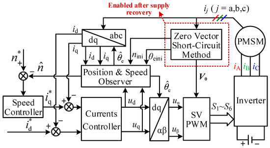
Figure 1.
Diagram of sensorless PMSM flying restart control scheme based on the ZVSM.
According to the times of zero vector short-circuits, existing methods can be separated into: single zero vector short-circuit method; double zero vector short-circuit method; three zero vector short-circuit method; and repetitive zero vector short-circuit method. Increasing the times of zero vector short-circuits helps to broaden the application range of the ZVSMs and improve the estimation accuracy of the speed and rotor position. However, as can be seen from Figure 2, the more times of zero vector short-circuits, the longer the time from the recovery of power supply to the first rise of the electromagnetic torque to its reference value, thus reducing the electromagnetic torque response speed after the power supply recovers.
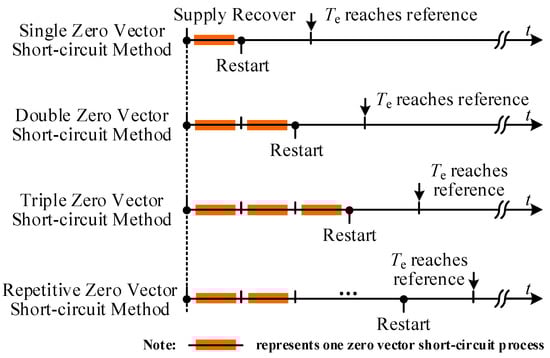
Figure 2.
Influence of different zero vector short-circuit methods on the rise time of electromagnetic torque after power supply recovery.
3. Proposed Shoot-Through Zero Vector Short-Circuit Method
For the flying restart of the sensorless PMSM fed by qZSI, this paper proposes a shoot-through zero vector short-circuit method (SZVSM), so as to effectively shorten the rise time of electromagnetic torque after the power supply recovers while realizing a good estimation of the speed and rotor position before the motor restarts. In this method, the DC link voltage is regulated while the initial speed and rotor position are estimated before the motor restarts, which breaks the limitation of regulating qZSI’s DC link voltage under the normal operation of the motor in the conventional methods.
3.1. Design of Mixed Vector Insert Mode with a DC-Link Voltage Preboosting Scheme
Figure 3 shows the equivalent circuit of the qZSI-PMSM drive system. In this figure, uin is the input voltage of the qZSI; udc is the DC link voltage of the inverter; uC1 and uC2 are the voltages of capacitors C1 and C2; and iL1 and iL2 are the currents of inductors L1 and L2. Assuming the impedance network consisting of the two inductors and two capacitors is symmetrical, then L1 = L2 = L and C1 = C2 = C.
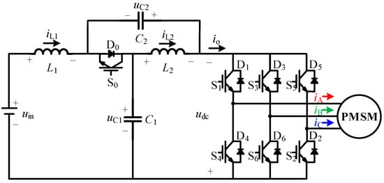
Figure 3.
Equivalent circuit of the PMSM system driven by qZSI.
The qZSI allows the inverter bridge to have a shoot-through state (a state where the upper and lower tubes of the same bridge arm are simultaneously conducted). In the shoot-through state, the inductor in the impedance network is charged and the energy stored in the inductor is released in the nonshoot-through state, thus maintaining the capacitor voltage in the network and pumping the DC link voltage. Moreover, the shoot-through vector of the qZSI not only makes the impedance network store energy, but also has the same effect on the load as the zero vector. According to this characteristic, a mixed vector insertion mode is designed by utilizing the shoot-through vector, zero vector, and empty vector. Taking the two short-circuit processes as an example, Figure 4 shows the diagram of the actions of different vectors before the flying restart. In this figure, Vj and Vk represent two basic active vectors, where j, k = 1, 2, …, 6; Vz represents the zero vector, where z = 0 or 7; Vn represents the empty vector (empty vector is defined as the vector when all switches in the inverter bridge are turned off); and Vsh represents the shoot-through vector. With the mixed vector insert mode, the inverter alternately outputs a shoot-through vector, a zero vector, and an empty vector before flying restart. Moreover, under the actions of the shoot-through vector and zero vector, the short-circuit currents are generated in three-phase stator windings; under the action of the empty vector, the short-circuit currents gradually decay to zero.
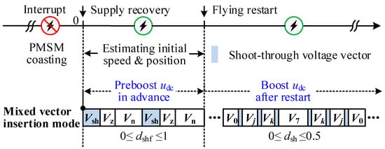
Figure 4.
Equivalent circuit of the PMSM system driven by qZSI.
As can be seen in Figure 4, on one hand, the shoot-through vector is used to generate stator short-circuit currents so as to extract the speed and rotor position information before the flying restart; on the other hand, the shoot-through vector is used to realize the preboost of the qZSI’s DC link voltage. Take test to represent the time required for estimating the initial speed and position before the motor restarts: tr is the time from the restart of the motor to the first rise of the electromagnetic torque to its reference value; trcv is the waiting time for the electromagnetic torque to reach its reference value after the power supply recovers, and it meets trcv = test + tr. Under the effect of mixed vectors, the qZSI has ability to preboost the DC link voltage before the flying restart, so it is possible that the inverter outputs higher voltage immediately when the motor restarts, thus providing beneficial condition to shorten trcv.
3.2. Analysis of DC-Link Voltage Preboosting Condition before Flying Restart
With the insert mode of mixed vectors shown in Figure 4, the qZSI has the ability to preboost the DC link voltage before the flying restart, but it cannot ensure that the DC link voltage is certainly boosted before the motor restarts. To further analyze the condition for ensuring the DC link voltage can be boosted before flying restart, the qualitative change in the qZSI’s inductor current and capacitor voltage under the actions of mixed vectors are firstly given, as shown in Figure 5.
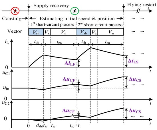
Figure 5.
Diagram of the variation in iL, uC1, and uC2 under the mixed vectors.
In Figure 5, tsc is the action time sum of short-circuit vectors, including shoot-through and zero vectors during one short-circuit process; tn is the action time of the empty vector; tsh is the action time of the shoot-through vector during one short-circuit process; dshf is the ratio of the shoot-through vector in the short-circuit vectors; tzn is the sum of the action time of the zero vector and empty vector during one short-circuit process, i.e., tzn = (1−dshf)tsc + tn; ΔiLF and ΔuCF are the increment of the inductor current and capacitor voltage at the end of the first short-circuit process; and ΔiLS and ΔuCS are the increments of the inductor current and capacitor voltage at the end of the second short-circuit process with respect to the instant t = 0, respectively.
The DC link voltage of the qZSI satisfies the following relationship under nonshoot-through state:
From (1), the increment of udc at the end of the second short-circuit process can be represented as 2ΔuCS. Thus, udc can be preboosted before the flying restart as long as ΔuCS > 0 is satisfied.
In order to facilitate the analysis of the qZSI’s inductor current and capacitor voltage variations under the actions of mixed vectors, Figure 6a shows the equivalent circuit under the action of the shoot-through vector; Figure 6b shows the equivalent circuit under the actions of the zero vector and empty vector.
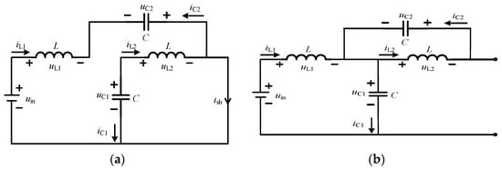
Figure 6.
Equivalent circuits of the qZSI under different vectors: (a) shoot-through vector; (b) zero or empty vector.
As shown in Figure 5, the power supply has recovered before the actions of vectors, so the initial values of state variables at the moment t = 0 can be expressed as
As shown in Figure 6a, the inductor L2 is charged by capacitor C1 and the inductor L1 is charged by the power supply under the action of the first shoot-through vector from the moment t = 0. The corresponding state equations can be expressed as
Combining (2) and (3), the state variables can be solved as
Afterward, the zero vector is applied at the moment t = dshftsc. As shown in Figure 6b, the capacitor C2 is charged by inductor L2 and the capacitor C1 is charged by both the power supply and inductor L1 under the action of the zero vector. Following the zero vector, the empty vector is applied. Under the action of the empty vector, there are two possible cases according to the back EMF amplitude of the motor. In the first case, if the back EMF amplitude is less than or equal to the voltage of capacitor C1, the DC link current is zero and the motor will not recharge the impedance network; in the second case, if the back EMF amplitude is larger than the voltage of capacitor C1, there is a reverse DC link current and the motor will recharge the impedance network, which will increase the capacitor charging current and then the capacitor voltage further. Comparing the two cases, it is easy to find that the increment of the DC link voltage in the first case is less than that in the second case. Therefore, it is only necessary to ensure that ΔuCS > 0 is satisfied in the first case. Since the changes of each state variable in the impedance network under the action of the empty vector are the same as those under the action of the zero vector, it can be considered that the equivalent circuits of the qZSI under the zero vector and empty vector are the same.
From Figure 6b, the following state equations are obtained as
Substituting t = dshftsc into (4), the initial values of the state variables in (5) before the action of the zero vector can be obtained. Then, the values of state variables at the end of the first short-circuit process, that is, t = tsc + tn, can be obtained as follows by solving (5):
where ω0 = 1/.
Subtracting (2) from (6), it can be obtained that the increments of the state variables at the end of the first short-circuit process satisfy ΔuC1 = ΔuC2 = ΔuCF, ΔiL1 = ΔiL2 = ΔiLF, where ΔuCF and ΔiLF are expressed as
Similarly, the increments of the capacitor voltage and inductor current at the end of the second short-circuit process relative to the initial values in (2) can be derived as
By observing (7) and (8), it can be found that ΔuCF and ΔuCS are greater than zero when the following relationship shown in (9) is satisfied:
Since the smaller tzn is helpful to reduce the rise time of electromagnetic torque after the power supply recovers, k = 0 is taken in (9).
Substituting (10) into (9), it can be deduced that
Thus, the DC link voltage udc can be preboosted before the flying restart when dshf satisfies the inequality in (11). It should be noted that the inequality is only a sufficient condition to ensure ΔuCS > 0, which is helpful to save much calculation burden and complicated analysis in engineering application.
3.3. Initial Speed and Position Estimation before Flying Restart
In Section 3.2, according to the principle of ensuring that the DC link voltage is preboosted before the flying restart, the constraints that the duty cycle of the shoot-through vector should satisfy are derived. On this basis, by analyzing the influence of different vectors on the stator current, the initial speed, and rotor position before the motor restarts are extracted.
As the shoot-through vector has the same effect on the load as the zero vector, the short-circuit currents in three-phase stator windings is generated by applying the shoot-through vector and the zero vector to the inverter in turn; then, the short-circuit currents gradually decay to zero by applying the empty vector. Figure 7 shows the principle of obtaining the initial speed and position before the motor restarts under the actions of different vectors.
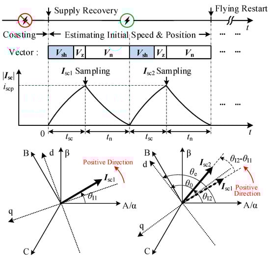
Figure 7.
Principle of obtaining initial speed and rotor position under the proposed SZVSM.
As shown in Figure 7, |Isc| is the amplitude of stator phase current vector; iscp is the peak value of the short-circuit phase current vector’s amplitude; Isc1 and Isc2 represent short-circuit phase current vectors after the first and second actions of the shoot-through vector and zero vector, respectively; θI1 and θI2 are the phase angles of Isc1 and Isc2 relative to axis A in the three-phase stator coordinate system, respectively; θ0 is the phase angle of Isc2 relative to d-axis in dq coordinate system; and θe is the rotor position angle.
It can be seen from Figure 7 that Isc1 and Isc2 are obtained by sampling the phase current at the end of the actions of short-circuit vectors. The phase angles of Isc1 and Isc2 relative to A axis are expressed as follows by coordinate transformation:
where k = 1, 2.
Since the interval between the twice short-circuit current samplings is tn + tsc, the average electrical angular frequency during this interval can be expressed as
It should be noted that (13) holds under the condition that
where ωemax is the maximum electrical angular velocity.
In general, tn + tsc is much less than the mechanical time constant of the motor, so it can be considered that the average electrical angular velocity in the two short-circuit processes is approximately equal to the initial electrical angular velocity ωeini when the motor restarts; that is, ≈ ωeini. Then, the initial speed before the flying restart is obtained as
In order to obtain the rotor position further, the voltage equations in the d–q axis coordinate system are given as
where ud, uq, id, and iq are the stator voltages and currents of the d-axis and q-axis, respectively; Rs is the stator resistance; Ld and Lq are the equivalent inductances of the d-axis and q-axis; ωe is the electrical angular velocity; ψf is the permanent magnet flux; and p is the differential operator. Under the actions of the shoot-through and zero vectors, ud = uq = 0 and the initial values of the d-axis and q-axis currents are also zero, i.e., id(0) = iq(0) = 0. Furthermore, considering the short-time tsc is far less than the time constant Lq/Rs, Rs can be neglected, approximately. Substituting ud = uq = 0, id(0) = iq(0) = 0 and Rs = 0 into (16), it can be deduced that
From (17), it can be obtained as
From Figure 7, the rotor position angle at the second sampling instant of the short-circuit current is
According to Figure 7, the interval between the moment of the second current sampling and the moment when the motor restarts is tn. Since tn is very small, θe at the moment of the second current sampling is approximately considered as the initial rotor position angle θeini at the instant of flying restart.
4. Implementation and Experimental Results
The diagram of the sensorless flying restart control scheme based on the proposed SZVSM is shown in Figure 8.
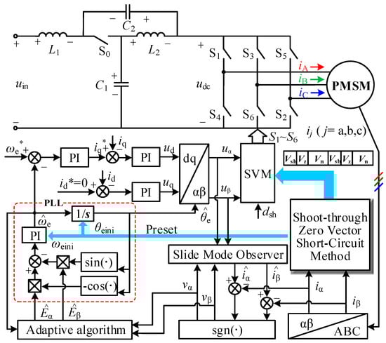
Figure 8.
Diagram of sensorless flying restart control scheme based on the proposed SZVSM.
The classical vector control strategy with speed and current double-closed loop is adopted to drive the motor. Moreover, the speed loop controller’s parameters are set as knp = 0.025 and kni = 0.1, and the current loop controller’s parameters are set as kip = 0.025 and kii = 0.1. Considering the motor usually runs at medium and high speed in the process of flying restart and the back EMF amplitude is large, the traditional sensorless control algorithm based on back EMF observation is adopted to obtain the speed and position of the motor during normal operation, and illustrates the role of the SZVSM during the flying restart. As shown in Figure 8, the back EMF is first obtained by an adaptive sliding mode observer [25]. After the back EMF obtained passes through the phase-locked loop (PLL), the electrical angular velocity of the motor can be obtained, and then the estimated value of the rotor position can be obtained after integrating . When the power supply is interrupted, the variables in the PI regulator and the integrator used for acquiring in the PLL are cleared, which may cause a large deviation of the speed and rotor position estimated by the traditional back EMF method after the power supply recovers. To better meet the operating demand of flying restart of the motor, the proposed SZVSM should be used first to obtain the accurate initial speed and position before the motor restarts, and then it provides good initial values for the regulator and integrator in the PLL. In this way, after the power supply recovers from the interruption, the traditional sensorless algorithm based on back EMF observation can come into normal state soon, thus sustaining the PMSM to restart normally without causing large inrush stator currents.
To verify the feasibility and effectiveness of the proposed method, the experiments are carried out on a 2.3 kW surface-mounted PMSM with a 1500 r/min rated speed and a 15 Nm rated torque. The prototype of the experimental system is shown in Figure 9. In the control unit, a DSP (TMS320F28335) is employed for realizing the major control algorithm and an FPGA serves as the role to accomplish auxiliary tasks, such as protection and communication. The insulated gate bipolar transistors (IGBTs) used in the qZSI is FF450R12ME4 and the phase current sensors installed are CHB-50A. The basic parameters of the PMSM and qZSI are shown in Table 1. In addition, the load of the tested motor is provided by a dynamometer driven by a SIEMENS S120 inverter.
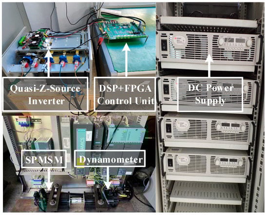
Figure 9.
Diagram of experiment prototype.

Table 1.
Parameters of PMSM and QZSI.
4.1. Comparative Experiment on Response Speed of Electromagnetic Torque in Flying Restart Process
The proposed SZVSM can effectively improve the response speed of the electromagnetic torque in the process of flying restart. The time trcv from the recovery of power supply to the first rise of the electromagnetic torque to its reference value is first compared among the traditional ZVSM, the combination scheme of the ZVSM and the dc-link voltage boosting after flying restart, and the proposed SZVSM. The parameter settings of three methods are shown in Table 2, in which dshf is the ratio of the shoot-through vector in the short-circuit vectors during one short-circuit process before the motor restarts, and dsh is the duty cycle of the shoot-through vector after the motor restarts.
Table 2.
Parameter settings of the three methods.
In the experiment, the input voltage of the qZSI is set as uin = 315 V. The dc-link voltage control is adopted by open-loop mode before the motor restarts; when the PMSM system driven by the qZSI operates normally after the flying restart, a double closed control method with inner inductor–current loop and outer capacitor–voltage loop is adopted by the qZSI.
During the operation of the motor with rated speed 1500 r/min, all the switches of the qZSI are turned off intentionally for a short period to simulate the momentary interruption of power supply. After 2 ms, all switch signals are re-enabled to simulate the recovery of the power supply. For comparison, Figure 10 shows the experimental waveforms during the flying restart under the traditional ZVSM, the combination scheme of the ZVSM and the dc-link voltage boosting after flying restart, and the proposed SZVSM.
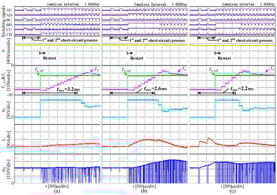
Figure 10.
Experiments to compare the response speed of the electromagnetic torque in the flying restart process under three methods: (a) traditional ZVSM; (b) combination scheme of the ZVSM and the dc-link voltage boosting after restart; and (c) proposed SZVSM.
As shown in Figure 10, AU, BU, and CU represent the switching signals of the power devices in the inverter’s upper arms; AD, BD, and CD represent the switching signals of the power devices in the inverter’s lower arms; n is the actual motor speed; Te_ref and Te are the reference value and actual value of the electromagnetic torque, respectively, and Te_ref is also the output of the speed controller; uq is the q-axis stator voltage and also the output of the q-axis current controller; and iL and udc are the inductor current and dc-link voltage of the qZSI, respectively.
Comparing Figure 10a,c, it can be seen that the time trcv from the recovery of the power supply to the first rise of the electromagnetic torque to its reference value is 3.2 ms under the traditional ZVSM, while trcv is shortened to 2.2 ms under the proposed SZVSM. As shown in Figure 10, the output uq of the q-axis current regulator reached the saturation value after the motor restarts, indicating that the output voltage of the inverter cannot be increased any more by increasing the modulation index in the linear modulation area of the inverter at this time. Thus, the reason for the obvious reduction in trcv under the proposed SZVSM is that the dc-link voltage is boosted.
It should be noted that the way of boosting dc-link voltage in the proposed method is different from that in the conventional method. In the conventional control of the qZSI, the boost of the dc-link voltage is carried out under the normal operation of the motor. That is, the shoot-through vector must be inserted after the motor restarts. However, the proposed method can achieve the boost of the dc-link voltage before the motor restarts (which is also called preboost). By comparing Figure 10b,c further, it can be seen that the dc-link voltage boosted at the moment when the motor restarts by adopting the proposed method, while under the combination scheme, the dc-link voltage starts to rise slowly after the motor restarts. Although the time trcv is shorten to 2.6 ms, as shown in Figure 10b, compared with trcv = 3.2 ms indicated in Figure 10a, it is still longer than trcv = 2.2 ms that is shown in Figure 10c.
To summarize, the experimental results illustrate that the preboost of the qZSI’s dc-link voltage during the abnormal operation of the motor can be achieved under the proposed SZVSM, which effectively shortens the time required for the electromagnetic torque to reach its reference value after the power supply recovers, so that it gives the sensorless flying restart method a faster torque response speed when applied in the PMSM system driven by qZSIs.
4.2. Experiment on Initial Speed and Position Estimation before Flying Restart
The proposed SZVSM can make up for the insufficiency of the traditional ZVSM in the electromagnetic torque response speed, but the basic goal of these two methods is to complete the estimation of the initial speed and position before the motor restarts. Thus, the performance of these two methods in estimating the initial speed and rotor position is compared. In accordance with the experimental conditions in Section 4.1, the experimental waveforms obtained are shown in Figure 11.
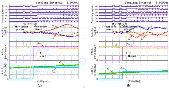
Figure 11.
Experiments to compare the estimation of the initial motor speed and rotor position under different methods: (a) traditional ZVSM; (b) proposed SZVSM.
As shown in Figure 11, the meaning of the symbols AU, AD, BU, BD, CU, and CD are the same as those in Figure 10; iA, iB, and iC are the three-phase stator currents; nini and θeini are the estimated values of the initial speed and rotor position, respectively; and n and θe are the actual speed and rotor position obtained by the position sensors, respectively, which are comparisons to evaluate the accuracy of the estimated values. According to Figure 11, an error analysis is made on the initial speed and rotor position estimated by the traditional ZVSM and proposed SZVSM, respectively, as shown in Table 3. As can be seen from Table 3, the estimation accuracy of the initial speed is slightly decreased in the proposed SZVSM compared with that in the ZVSM, while the estimation accuracy of the initial rotor position is slightly improved. Considering the uncertainty of sampling error within a certain range, it can be considered that the performances of the two methods in terms of initial speed and rotor position estimation are basically the same.
Table 3.
Estimated error of initial speed and rotor position.
5. Conclusions
In this paper, a shoot-through zero vector short-circuit method is proposed for the flying restart of the sensorless PMSM driven by qZSI. The proposed method achieves important progress in the following aspects:
- (1)
- The qZSI’s dc-link voltage is regulated while the initial speed and position are estimated before the motor restarts, and it breaks the limitation of regulating the qZSI’s dc-link voltage during the normal operation of the motor in conventional methods.
- (2)
- The proposed method can realize the accurate estimation of the initial speed and position before the motor restarts, which provides good initial values for the traditional sensorless estimation algorithm.
- (3)
- The proposed method realizes the preboost of the qZSI’s dc-link voltage during the abnormal operation before the motor restarts, which improves the response speed of electromagnetic torque for the sensorless PMSM in the flying restart process.
The proposed method is especially suitable for applications such as electric vehicles and servo spindles that require both flying restart and higher electromagnetic torque response speed. However, it should be noted that this method does not consider the influence of control loop delay and motor parameter variation on rotor position estimation error. In order to enhance the estimation accuracy, further research can be carried out from the aspects of control delay compensation, parameter identification, and multizero vector insertion, among others.
Author Contributions
Writing—original draft preparation, Y.C. and S.X.; writing—review and editing, Z.L. All authors have read and agreed to the published version of the manuscript.
Funding
This work was supported in part by the Major Program of National Natural Science Foundation of China under Grant 51991384 and in part by the Zhejiang Provincial Natural Science Foundation of China under Grant LQ21E070007.
Institutional Review Board Statement
Not applicable.
Informed Consent Statement
Not applicable.
Data Availability Statement
Not applicable.
Conflicts of Interest
The authors declare no conflict of interest.
References
- Ullah, K.; Guzinski, J.; Mirza, A.F. Critical review on robust speed control techniques for permanent magnet synchronous motor (PMSM) speed regulation. Energies 2022, 15, 1235. [Google Scholar] [CrossRef]
- Nicola, M.; Nicola, C.I.; Selișteanu, D. Improvement of PMSM sensorless control based on synergetic and sliding mode controllers using a reinforcement learning deep deterministic policy gradient agent. Energies 2022, 15, 2208. [Google Scholar] [CrossRef]
- Chen, B.; Wang, K.; Le, Y. High-precision position error correction method for the PMSM based on low-order harmonic suppression. IEEE Trans. Power Electron. 2021, 36, 4500–4512. [Google Scholar] [CrossRef]
- Mini, Y.; Nguyen, N.K.; Semail, E.; Vu, D.T. Enhancement of sensorless control for non-sinusoidal multiphase drives-part I: Operation in medium and high-speed range. Energies 2022, 15, 607. [Google Scholar] [CrossRef]
- Yin, S.; Xia, J.; Zhao, Z.; Zhao, L.; Liu, W.; Diao, L.; Jatskevich, J. Fast restarting of free-running induction motors under speed-sensorless vector control. IEEE Trans. Ind. Electron. 2020, 67, 6124–6134. [Google Scholar] [CrossRef]
- Chen, J.; Li, J.; Qu, R.; He, K.; Tao, L. A restart strategy of a rotating induction machine for inrush current elimination. IEEE Trans. Ind. Appl. 2020, 56, 4906–4914. [Google Scholar] [CrossRef]
- Horie, T.; Kondo, K. Experimental study on a restarting procedure at coasting condition for a rotational angle sensorless PMSM. IEEJ J. Ind. Appl. 2014, 3, 131–137. [Google Scholar] [CrossRef]
- Chen, B.; Shen, A.; Li, P.; Luo, X.; Xu, S.; Xu, J. Restart strategy for sensorless PMSM drive system based on zero-voltage vector. IET Electr. Power Appl. 2020, 14, 2362–2369. [Google Scholar] [CrossRef]
- Son, Y.; Jang, S.; Nasrabadi, R. Permanent Magnet AC Motor Systems and Control Algorithm Restart Methods. U.S. Patent 08054030, 11 August 2011. [Google Scholar]
- Yamakawa, T.; Wakao, S.; Kondo, K.; Yoneyama, T.; Taniguchi, S.; Mochizuki, S. Starting procedure of rotation sensorless PMSM at coasting condition for railway vehicle traction. Elect. Eng. Jpn. 2009, 169, 56–63. [Google Scholar] [CrossRef]
- Taniguchi, S.; Mochiduki, S.; Yamakawa, T.; Wakao, S.; Kondo, K.; Yoneyama, T. Starting procedure of rotational sensorless PMSM in the rotating condition. IEEE Trans. Ind. Appl. 2009, 45, 194–202. [Google Scholar] [CrossRef]
- Lee, K.; Ahmed, S.; Lukic, S. Universal restart strategy for high-inertia scalar-controlled PMSM drives. IEEE Trans. Ind. Appl. 2016, 52, 4001–4009. [Google Scholar] [CrossRef]
- Seo, D.; Bak, Y.; Lee, K. An improved rotating restart method for a sensorless permanent magnet synchronous motor drive system using repetitive zero voltage vectors. IEEE Trans. Ind. Electron. 2020, 67, 3496–3504. [Google Scholar] [CrossRef]
- Seo, D.; Bak, Y.; Cho, S.; Bae, K.; Lee, K.-B. An improved flying restart method of sensorless PMSM drive systems fed by an ANPC inverter using repetitive zero voltage Vectors. In Proceedings of the IEEE Applied Power Electronics Conference and Exposition, Anaheim, CA, USA, 17–21 March 2019. [Google Scholar]
- Liu, D.; Guo, X.; Lei, Y.; Wang, R.; Chen, R.; Chen, F.; Li, Z. An improved control strategy of PMSM drive system with integrated bidirectional DC/DC. Energies 2022, 15, 2214. [Google Scholar] [CrossRef]
- Zaid, M.; Lin, C.H.; Khan, S.; Ahmad, J.; Tariq, M.; Mahmood, A.; Sarwar, A.; Alamri, B.; Alahmadi, A. A family of transformerless quadratic boost high gain DC-DC converters. Energies 2021, 14, 4372. [Google Scholar] [CrossRef]
- Grgić, I.; Vukadinović, D.; Bašić, M.; Bubalo, M. Efficiency boost of a quasi-z-source inverter: A novel shoot-through injection method with dead-time. Energies 2021, 14, 4216. [Google Scholar] [CrossRef]
- Liu, W.; Yang, Y.; Kerekes, T.; Blaabjerg, F. Generalized space vector modulation for ripple current reduction in quasi-Z source inverters. IEEE Trans. Power Electron. 2021, 36, 1730–1741. [Google Scholar] [CrossRef]
- Liang, W.; Liu, Y.; Peng, J. A day and night operational quasi-Z source multilevel grid-tied PV power system to achieve active and reactive power control. IEEE Trans. Power Electron. 2021, 36, 474–492. [Google Scholar] [CrossRef]
- Mohmoudi, H.; Aleenejad, M.; Ahmadi, R. Torque ripple minimization for a permanent magnet synchronous motor using a modified quasi-Z-source inverter. IEEE Trans. Power Electron. 2019, 34, 3819–3830. [Google Scholar] [CrossRef]
- Shuai, D.; Qianfan, Z.; Weipan, Z.; Chaowei, Z.; Tuopu, N. A compound control strategy for improving the dynamic characteristics of the DC-link voltage for the PMSM drive system based on the quasi-Z-Source inverter. IEEE Access 2019, 7, 151929–151938. [Google Scholar] [CrossRef]
- Xiao, S.; Gu, X.; Wang, Z.; Shi, T.; Xia, C. A novel variable DC-link voltage control method for PMSM driven by a quasi-Z-source inverter. IEEE Trans. Power Electron. 2020, 35, 3878–3890. [Google Scholar] [CrossRef]
- Subhani, N.; Kannan, R.; Mahmud, A.; Blaabjerg, F. Z-source inverter topologies with switched Z-impedance networks: A review. IET Power Electron. 2021, 14, 727–750. [Google Scholar] [CrossRef]
- Rahman, S.; Meraj, M.; Iqbal, A.; Tariq, M.; Maswood, A.I.; Ben-Brahim, L.; Al-Ammari, R.; Syed, R.; Mohammad, M. Design and implementation of cascaded multilevel qZSI powered single-phase induction motor for isolated grid water pump application. IEEE Trans. Ind. Appl. 2020, 56, 1907–1917. [Google Scholar] [CrossRef]
- Qiao, Z.; Shi, T.; Wang, Y.; Yan, Y.; Xia, C.; He, X. New sliding-mode observer for position sensorless control of permanent-magnet synchronous motor. IEEE Trans. Ind. Electron. 2012, 60, 710–719. [Google Scholar] [CrossRef]
Publisher’s Note: MDPI stays neutral with regard to jurisdictional claims in published maps and institutional affiliations. |
© 2022 by the authors. Licensee MDPI, Basel, Switzerland. This article is an open access article distributed under the terms and conditions of the Creative Commons Attribution (CC BY) license (https://creativecommons.org/licenses/by/4.0/).