Article

Optimization Design of Unequal Amplitude Modulated Poles for the Bearingless PMSM

1
School of Electrical Engineering, Tiangong University, Tianjin 300387, China
2
School of Electrical and Information Engineering, Tianjin University, Tianjin 300072, China
*
Author to whom correspondence should be addressed.
Energies 2022, 15(9), 3097; https://doi.org/10.3390/en15093097
Submission received: 16 February 2022 / Revised: 10 March 2022 / Accepted: 14 March 2022 / Published: 24 April 2022

Abstract

:
The structural parameters of an equal amplitude modulated magnetic pole is limited by the length of the air-gap. When the modulation ratio or carrier ratio is small, the spacing of permanent magnets is too large, which will lead to a worse cogging effect, and then the torque optimization effect is not satisfying. In order to improve the operation stability of a bearingless permanent magnet synchronous motor (bearingless PMSM), an unequal amplitude modulated magnetic pole structure is proposed according to the principle of magnetic pole modulation. The Taguchi method is used to optimize the structural parameters of the unequal amplitude modulated magnetic pole with the goal of reducing the torque and suspension force fluctuation. Three kinds of magnetic pole structures, named the whole magnetic pole, the equal amplitude modulated magnetic pole and the unequal amplitude modulated magnetic pole are compared and verified. The results show that the proposed structure of the unequal amplitude modulated magnetic pole can effectively further decrease the torque and suspension force fluctuations under the premise of the output capacity of the motor being unchanged, which improves the performance of the bearingless PMSM.

1. Introduction

A bearingless PMSM normally has two sets of windings: torque winding and suspension winding, respectively. When the suspension winding is supplied with a suitable current, the airgap magnet field will contain a bias component, thereby generating a suspension force to suspend the rotor. The problem of life shortening of traditional mechanical bearings due to increased friction during high-speed operation can be avoided. The operation and maintenance cost of the motor can also be reduced [1,2]. In recent years, the design of bearingless motors and the application of various control methods have improved its operation stability and promoted its application in special transmission occasions, such as vacuum and ultra-clean [3,4].
Radial and tangential components of the electromagnetic force between the stator and rotor of bearingless PMSM are closely related to the air-gap flux density distribution. An analytical model of the radial suspension force of bearingless PMSM is proposed in [5], which points out the source of suspension force fluctuation. In order to improve the distribution of the air-gap magnetic field generated by the stator, the air-gap magnetic field modulation method is proposed by slotting the stator tooth [6,7]. The auxiliary coil structure is proposed in the literature [8,9]. The number of turns of the auxiliary winding is optimized by using the magneto-motive force star diagram method, and the torque and suspension force fluctuation is reduced effectively in order to modulate the air-gap magnetic field generated by the stator. In order to improve the magnetic field distribution of the air-gap generated by the rotor, the Halbach permanent magnet array, combined magnetic pole, and eccentric magnetic pole are adopted in literature [10,11,12], which effectively reduced the fluctuation of torque and suspension force. However, these rotor structures increase the difficulty and cost of motor manufacturing in the actual machining process. The circumferential subsection method of magnets can improve the sinusoidal characteristics of the air-gap flux density of surface-mounted PMSM, that is, by changing the number and size of permanent magnets at each pole and making them arranged in the circumferential direction of the rotor by a certain rule so that the purpose of reducing the harmonic content of the air-gap flux density can be achieved [13,14] and can effectively weaken the cogging torque. As a method of the circumferential segment of magnetic poles, magnetic pole modulation technology determines the width and position of each permanent magnet by using the pulse-width modulation principle, which can suppress the air-gap flux density harmonics generated by permanent magnets effectively. The Fourier decomposition method establishes equations based on the harmonic coefficient expression of the air-gap magnetic density to calculate the position of permanent magnets to eliminate harmonics [15]. However, the more harmonics need to be eliminated, the more blocks of permanent magnet will be. Therefore, a permanent magnet block structure with the same thickness and different grades is used to modulate and eliminate harmonics in [16,17]. However, the elimination of some harmonics will lead to the increase of other harmonics, so the suppression effect of torque ripple cannot be guaranteed. The spatial position of each permanent magnet of the modulated magnetic pole was deduced by using the principle of equal area, and the no-load air-gap flux density of the motor was analyzed in [18]. It is pointed out that the harmonic distortion rate of the air-gap flux density of the modulated magnetic pole is reduced compared with the whole magnetic pole. However, when using an equal amplitude modulated magnetic pole, the variation of modulation ratio is limited due to the limited length of the air-gap and the change of modulation ratio determines the width of the permanent magnet block directly. In order to ensure the rotor MMF at one pole is unchanged, the thickness of the permanent magnet increases with the decrease of the width of the permanent magnet. In order to avoid overlapping, the maximum modulation ratio can only be 1. The thickness of the intermediate permanent magnet block cannot be infinitely reduced, and the thickness of the permanent magnet block cannot be increased without restriction because the thicker the permanent magnet block is, the greater the reluctance is, which will lead to the invisible increase effect of flux provided by the permanent magnet to the external magnetic circuit, and the output torque amplitude cannot be guaranteed. What is more, with the increase of the permanent magnet block thickness, the cogging effect will be increased, resulting in the effect of torque ripple optimization decrease. The analytical model of the modulated magnetic pole was derived in [19], and the variation of air-gap flux density harmonics with permanent magnet block parameters under different carrier ratios is studied by using the analytical model.
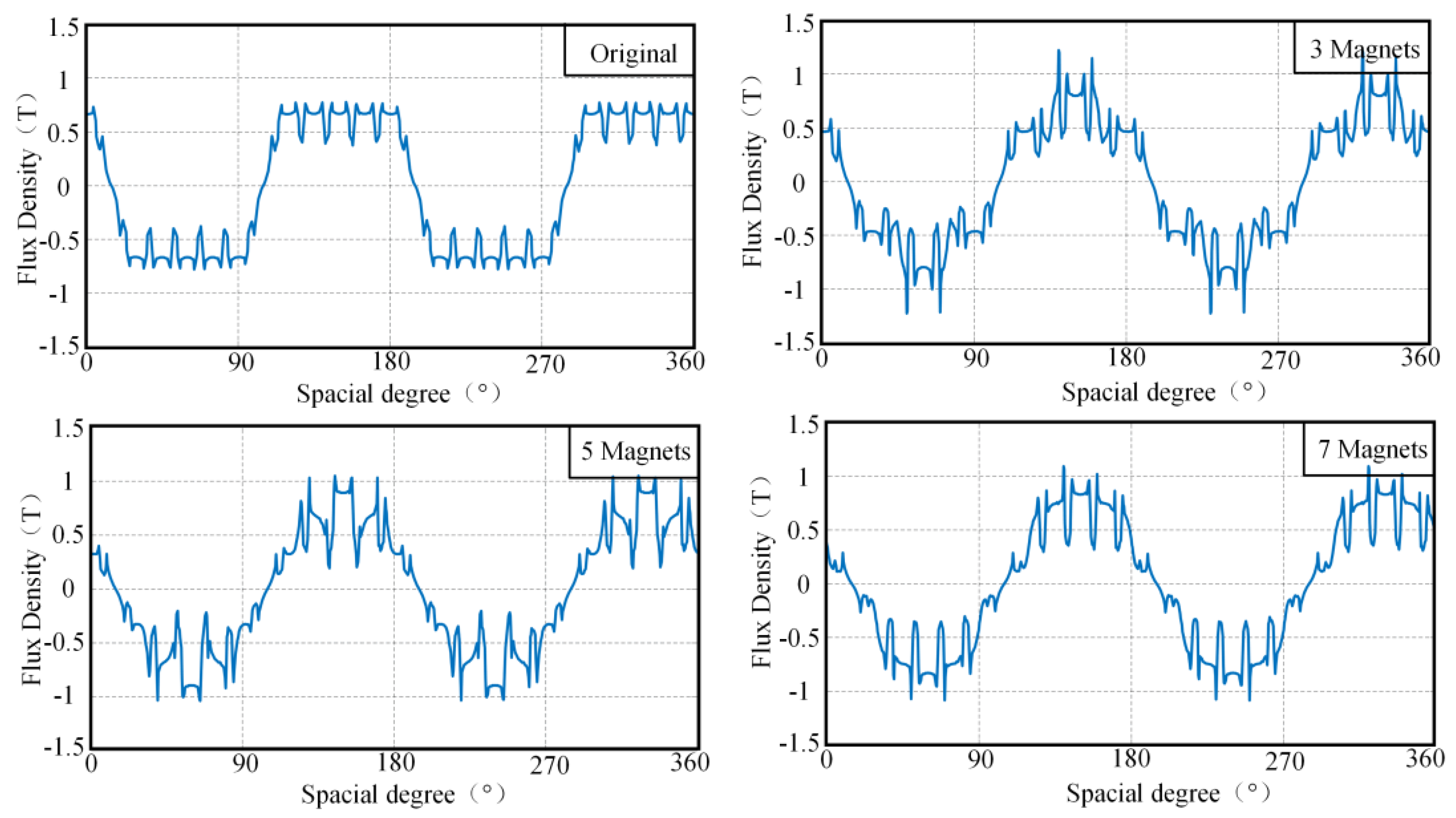
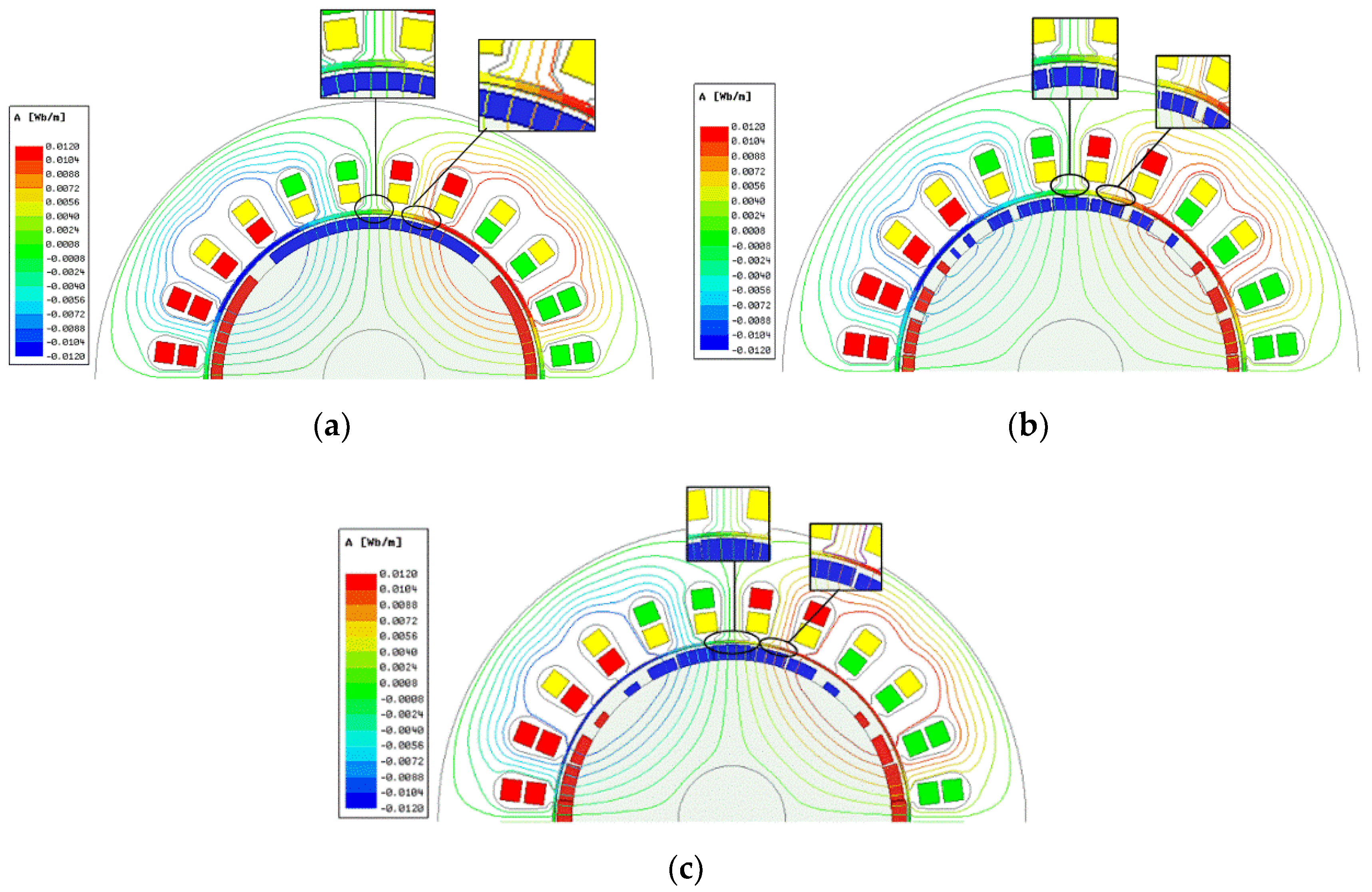
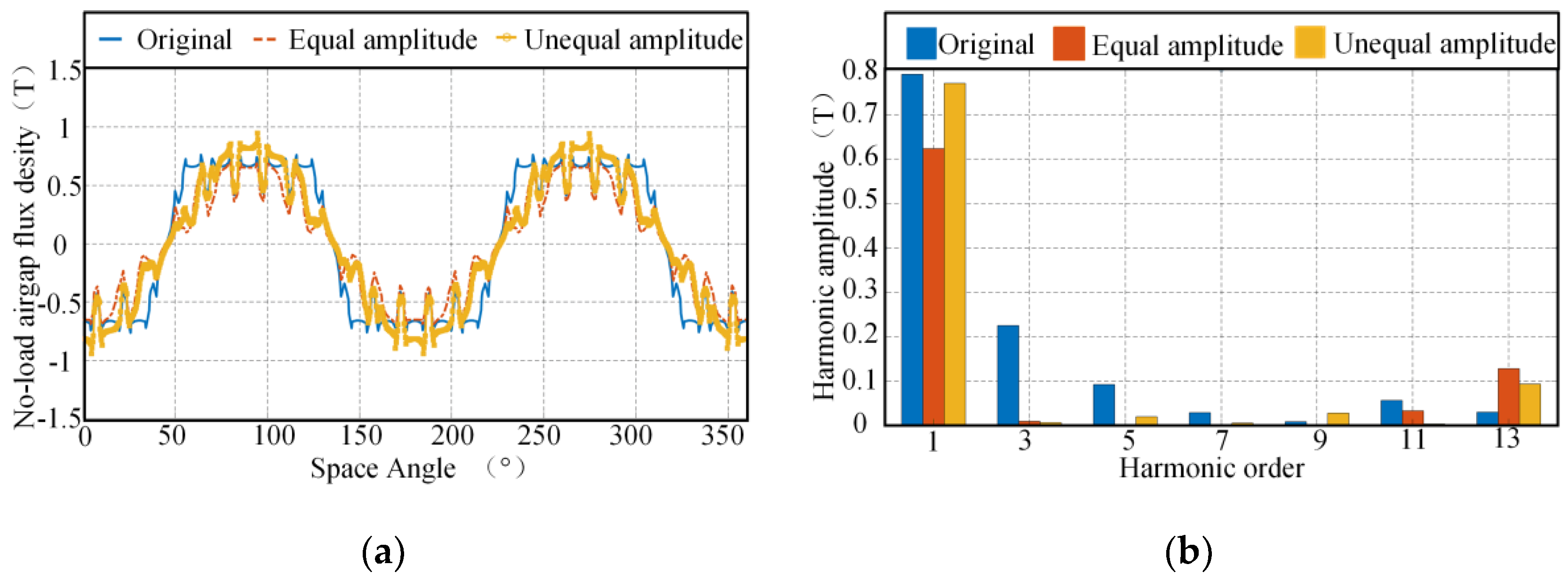
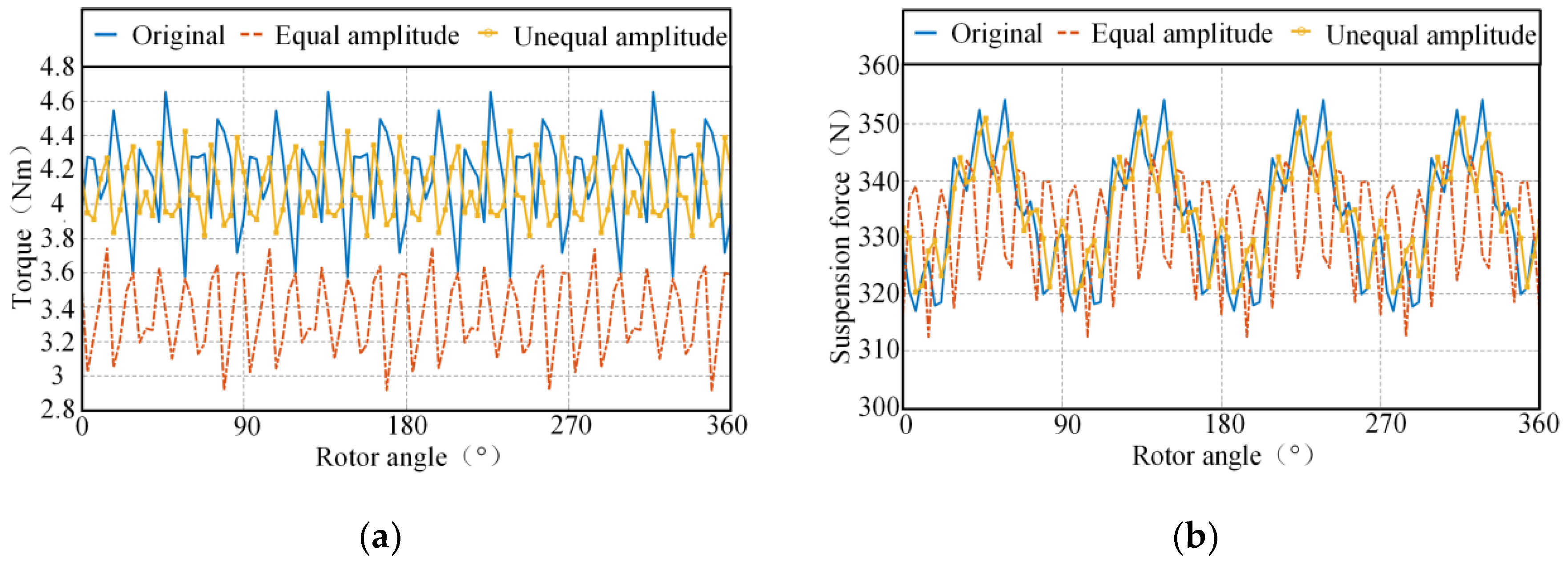
In order to solve a series of problems caused by the limited range of the modulation ratio of the equal amplitude modulated magnetic poles, an unequal amplitude permanent magnet width modulation method, that is, carrier waves with different amplitudes is used to modulate the wave proposed for bearingless PMSM in this paper. This method effectively improves the inflexible adjustment of magnetic pole parameters in equal amplitude modulated magnetic design. At the same time, the Taguchi method is used to optimize the design. The best parameter combination of the unequal amplitude modulation permanent magnet is achieved. The structure of the whole magnetic pole, the structure of the equal amplitude modulation magnetic pole and the structure of the unequal amplitude modulation magnetic pole are compared and analyzed by the finite element method. The results show that the unequal amplitude modulated magnetic pole structure can guarantee the output capacity of the motor and effectively improve the running stability of the motor.

2. Principle of Bearingless PMSM

The radial suspension force on the surface of the rotor of the bearingless PMSM is mainly generated by the interaction between the magnetic fields of the suspension winding and permanent magnets, which can be decomposed into x-axes and y-axes as follows:
F x = π l a r B s B f 2 μ 0 cos ( θ s θ f ) F y = π l a r B s B f 2 μ 0 sin ( θ s θ f )
where r is the radius of the rotor, Bs is the air-gap flux density generated by the suspension winding, Bf is the air-gap flux density generated by the permanent magnet, θs is the initial angle of the suspension winding current, and θf is the initial angle of the permanent magnet.
According to the Lorentz force calculation formula, the electromagnetic torque of the surface mount permanent magnet synchronous motor can be expressed as:
T = π l a R s 2 μ 0 0 2 π F f a φ , t B m φ , t d φ
where Ffa (φ, t) is the current distribution function of the torque winding, and Bm (φ, t) is the air-gap flux density distribution function.
It can be seen from the above analysis that the suspension force and torque of bearingless PMSM are closely related to the distribution of the permanent magnetic field and optimizing the rotor MMF generated by permanent magnets is an effective way to optimize the torque and suspension force of the motor.
The influences of core saturation and stator slotting are ignored. The relationship between the rotor MMF of the surface mount permanent magnet motor and the size of the permanent magnet meets the following equation:
F PM = ϕ PM R g = 1 b 0 B r l PM d PM σ 0 R g
where ϕPM is the main flux provided by the permanent magnet, Rg is the air-gap reluctance, b0 is the no-load working point of the permanent magnet, lPM is the axial length of the permanent magnet, dPM is the width of the permanent magnet, and σ0 is the no-load flux leakage coefficient.
It can be seen from Formula (3) that the sinusoidal distribution of the rotor MMF can be improved by dividing the magnetic poles and optimizing the width and position of each permanent magnet block, and the purpose of optimizing the torque and suspension force of the bearingless PMSM can be realized.

3. Unequal Amplitude Permanent Magnet Width Modulation Method

3.1. Equal Amplitude Modulation

The desired sine wave is taken as a modulation wave and the triangular wave is taken as a carrier. These two waves will intersect by selecting appropriate carrier ratio (number of triangular waves) and modulation ratio (ratio of sine wave amplitude to triangular wave amplitude) and the series of square waves generated are the arrangements of each permanent magnet block at one pole, that is, the modulated magnetic pole which is shown in Figure 1.
Based on the equal area principle, the area of each square wave is equal to the area of the sine wave within the corresponding sampling period, and the equation is as follows:
L n h m = ( n 1 ) L c n L c h sin sin θ e d θ e
where Ln is the nth square wave width, Lc is the sampling period, hsin is the amplitude of the sine wave, hm is the amplitude of the triangular wave, θe is the electrical angle.
The magnetization direction length of each permanent magnet block hPM = hm and the width of the nth permanent magnet block dPM(n) and the width of the square wave Ln satisfy the equation as follows:
L n = t 2 n t 2 n 1 d PM ( n ) = L n p PM
where pPM is the pole pair of the rotor.
According to the above principle, a small modulation ratio or carrier ratio means that the spacing of permanent magnets increases and the width of permanent magnets decreases. According to the principle of equal area, the thickness of PMs needs to be increased to ensure the MMF provided by the rotor under one pole. However, the thickness of the permanent magnet magnetic resistance is much larger than that of the air-gap. The thicker the permanent magnet is, the less significant increase of the flux provided by the PMs to the external magnetic circuit is. Besides, the increase of permanent magnet thickness will lead to the increase of the cogging effect, so the optimization effect of the torque wave is not satisfying. In order to overcome the above problems, the unequal amplitude modulated magnetic pole is proposed according to Equation (3) which shows that the value of the rotor MMF is related to the width of the permanent magnet.

3.2. Unequal Amplitude Modulation

Limited by the modulation ratio, the triangular wave amplitude hm and sine wave amplitude hsin should satisfy the relationship as follows:
h m h sin
The triangular waves with the same amplitude are applied to modulate the sine wave when taking the method of equal amplitude modulation in the process of modulation. It will cause a wider gap between adjacent pieces of the permanent magnet due to the narrow width of the permanent magnet blocks after modulation when the value of the sine wave is small in some of the sampling period (such as shown in Figure 1 in the first sampling period). It will add the motor cogging effect between the magnetic pole and stator core and is not conducive to the suppression of motor torque fluctuation. This phenomenon will be especially evident when it comes to a small value of carrier ratio or modulation ratio.
Therefore, the unequal amplitude modulation method is proposed in this paper, that is, the triangular wave with unequal amplitude is used as the carrier to modulate the sine wave in each sampling period. Take as an example that the carrier ratio is 5 as well. The schematic diagram of the unequal modulation method is shown in Figure 2. Where hsin is the amplitude of the modulation wave, and hmk is the kth (k = 0, 1, 2 … N) amplitude of the triangular wave.
Similarly, Mk is defined as the ratio of sine wave amplitude to the kth triangular wave amplitude, which is named modulation ratio:
M k = h sin h m k
According to the geometric similarity in Figure 2, each intersection point can be calculated by the formula as follows:
t 2 k + 1 = 2 k + 1 L c 2 L c 2 M k sin π k N t 2 k = ( 2 k 1 ) L c 2 + L c 2 M k sin π k N
Based on the equal area principle, the nth block sine wave and the nth block square wave area satisfy the relationship as follows:
h sin ( k 1 ) π N k π N sin θ e d θ e = h m n L m n
where hmn is the amplitude of the nth square wave.
The magnetization direction length of the n-th permanent magnet block lPM(n) = hmn (n = 0, 1, 2 … N) and the square wave width Ln also satisfy Equation (5).
The unequal amplitude modulated magnetic pole can change the modulation ratio under different sampling periods, so that the width of the permanent magnet increases and the thickness decreases, which can effectively increase the MMF of the rotor and reduce the influence of the cogging effect caused by the increase of thickness of permanent magnets. This method can increase the flexibility of the modulation of magnetic pole parameters effectively.

4. Optimal Design of Magnetic Pole with Unequal Amplitude Modulation

The Taguchi method is one of the common optimal methods in motor design. It can find a relatively effective combination solution of motor parameters in fewer tests to optimize the objective function. The variables of unequal amplitude modulated magnetic pole includes carrier ratio and modulation ratio, and the variable number of modulation ratio is related to carrier ratio. Therefore, the influence of carrier ratio on the harmonic distortion rate of the air-gap flux density is analyzed first. After selecting an appropriate carrier ratio, the modulation ratio can be selected at a variable level, and finally optimized by the Taguchi method.

4.1. Influence of Carrier Ratio

The main electromagnetic structure parameters of bearingless PMSM are shown in Table 1.
The proposed unequal amplitude modulation method is used to modulate the magnetic poles of the bearingless PMSM when the carrier ratio is 3, 5 and 7, respectively. The comparison results are shown in Figure 3 and Table 2.
As is shown in Figure 3 and Table 2, the sine wave of the no-load air-gap density of the bearingless PMSM is improved by the unequal amplitude modulation method under different carrier ratios. The harmonic distortion rate of the air-gap flux density waveform decreases; however, the improvement effect of sinusoidal degree tends to be gentle with the increase of the carrier ratio. In addition, the fundamental amplitude of the no-load air-gap magnetic density generated by the magnetic pole structure with unequal amplitude modulation is nearly unchanged, which provides a guarantee to keep the average value of torque and suspension force unchanged. Therefore, the carrier ratio of magnetic poles with unequal amplitude modulation should be reasonably selected based on the processing technology and the size of the motor pole distance.

4.2. Optimization Design by Taguchi Method

4.2.1. The Selection of Objective Function and Factor Level Table

Considering the difficulty of processing technology, the carrier ratio of unequal amplitude modulation magnetic pole is selected as 7 in this paper. On this basis, the Taguchi method was used to optimize the structure parameters of magnetic poles with unequal amplitude modulation with Mn (n = 0, 1, 2, 3) as the optimization variable, aiming at minimizing the fluctuation of torque and suspension force.
The objective function is determined for the optimization objectives selected:
G T = T max T min T max + T min × 100 %
G F = F max F min F max + F min × 100 %
where, Tmax and Tmin are the maximum and minimum values of torque waveform, respectively, and Fmax and Fmin are the maximum and minimum values of suspension force waveform, respectively.
Considering the size constraints of magnetic pole structure with unequal amplitude modulation and output capacity constraints, such as the mean value of torque and suspension force, the factor level table is shown in Table 3. The values of each modulation ratio meet Formula (7), where the value of hmk is greater than the sinusoidal wave value at the corresponding position. For example, when k = 1, hm1 > hsinsin(Lc1).

4.2.2. Orthogonal Test

According to the factor level table given in Table 3, L9 (34) orthogonal table is selected, and the finite element simulation of nine groups of motors with the structure of the unequal amplitude modulated magnetic pole in the orthogonal table is carried out. The results are shown in Table 4.
The average torque and suspension force of each factor in Table 4 at each level is calculated, and the average values of target GT and GF for each factor at each level are shown in Table 5 and Table 6 and Figure 4, respectively.
It can be seen from the results in Table 5 and Table 6 and Figure 4 that when the combination of structural parameters of the unequal modulation magnetic pole is M0(1)M1(2)M2(1)M3(3), the optimization effect of GT is the best and the motor torque fluctuation is the minimum. When the combination of structural parameters of the unequal modulation magnetic pole is M0(1)M1(2)M2(3)M3(3), the optimization effect of GF is the best, and the fluctuation of motor suspension force is the minimum. Only the value of factor M2 is different between the two groups of parameter combinations.
Furthermore, variance analysis is conducted on the data in Table 4 to obtain the proportion of influence of each factor on GT and GF, as shown in Table 7.
As can be seen from the results in Table 7, M2 has a greater influence on GF than GT, Therefore, the optimal parameter combination of the unequal modulation magnetic pole structure should be M0(1)M1(2)M2(3)M3(3).

4.3. Analysis of Results

The performances of the bearingless PMSM with the whole magnetic pole, equal amplitude modulated magnetic pole and unequal amplitude modulated magnetic pole are compared and analyzed.
The magnetization direction length of the whole magnetic pole and equal amplitude modulated magnetic pole are the same as the average value of that of permanent magnet blocks in the unequal amplitude modulated magnetic pole. The polar arc coefficient of the whole magnetic pole is the same as that of the unequal modulated magnetic pole. The carrier ratio of the equal amplitude modulated is 7 and the magnetic pole modulation ratio of the modulated magnetic pole is 1. The magnetic pole modulation ratio of the unequal amplitude modulated magnetic pole is the best parameter combination. Other electromagnetic structure parameters of the motor are the same.

4.3.1. No-Load Analysis

Figure 5 shows the comparison of the no-load magnetic flux line of bearingless PMSMs with three kinds of magnetic pole structures. It can be seen from the figure that the magnetic flux lines of the whole magnetic pole structure distribute evenly under one pole, while the magnetic flux lines of the unequal amplitude modulated magnetic pole are concentrated in the central position, but the magnetic flux lines of the equal amplitude modulated magnetic pole are relatively sparse. The flux lines produced by the unequal amplitude modulated magnetic pole are denser than those produced by the equal amplitude modulated magnetic pole, which is mainly due to the increase in the width of permanent magnets on both sides of the unequal amplitude modulated magnetic pole.
It can be seen that both modulation methods can effectively improve the air-gap flux density distribution, and the amplitude of the air-gap flux density base wave of the unequal amplitude modulated magnetic poles increases. According to Figure 6b, the no-load air-gap magnetic density decomposition diagram shows that the amplitude of the air-gap magnetic density base wave of the unequal amplitude modulated magnetic pole decreases slightly compared with the whole magnetic pole but increases significantly compared with the equal amplitude modulated magnetic pole. Compared with the equal amplitude modulated magnetic pole, the suppression effect of each harmonic is obviously improved.
The cogging torque of the bearingless PMSMs with three kinds of magnetic pole structures are simulated, and the comparison results are shown in Figure 7.
As can be seen that the maximum cogging torque of bearingless PMSM with the whole magnetic pole is 0.403 Nm, the maximum cogging torque of the bearingless PMSM with the equal amplitude modulated magnetic pole is 0.265 Nm, and the maximum cogging torque of the bearingless PMSM with the unequal amplitude modulation magnetic pole structure motor is 0.193 Nm. The equal amplitude modulated magnetic pole can reduce the cogging torque by 33.99%, and the unequal amplitude modulated magnetic poles can reduce the cogging torque by 50.2%.
It can be seen that the modulated magnetic pole structure has a certain optimization effect on the cogging torque. The decrease of the thickness of the permanent magnets on both sides of the unequal modulated magnetic pole reduces the cogging effect, so the cogging torque is further decreased.

4.3.2. Load Analysis

Two currents with an amplitude of 6A are applied to the two sets of windings, respectively. The comparison results of the torque and suspension force of the bearingless PMSMs with three kinds of rotor structures are shown in Figure 8.
As can be seen from Figure 8a, the average torque of the motor with the whole magnetic pole structure is 4.16 Nm and the torque fluctuation is 12.92%; the average torque of the motor with the equal amplitude modulated magnetic pole is 3.35 Nm and the torque fluctuation is 12.41%; the average torque of the motor with the unequal amplitude modulated magnetic pole is 4.12 Nm and the torque fluctuation is 7.35%. Compared with the motor with the whole magnetic pole. The decrease of torque fluctuation of the motor with the unequal-amplitude modulated magnetic pole is more obvious and the average torque is also improved compared with the motor with the equal amplitude modulated magnetic pole.
By changing the modulation ratio under different sampling periods, the structure parameters of the permanent magnets can be flexibly adjusted. Optimized by the Taguchi method, the torque has a better effect than that of the motor with the equal amplitude modulated magnetic pole, which effectively improves the problems caused by the limited range of the modulation ratio that exist in the equal amplitude modulated magnetic poles.
As can be seen from Figure 8b, the average suspension force of the motor with the whole magnetic pole is 333.55 N and its fluctuation is 7.72%; the average suspension force of the motor with the equal amplitude modulated magnetic pole is 332.25 N and its fluctuation is 4.89%; the average suspension force of the motor with the unequal amplitude modulated magnetic pole is 335.98 N and its fluctuation is 4.87%.
Therefore, the unequal amplitude modulated magnetic pole can effectively reduce the fluctuation of the motor suspension force, which is helpful to improve the operation performance of the bearingless PMSM.

5. Conclusions

In this paper, the problems existing in the design process of the equal amplitude modulated magnetic pole are improved. A design method for the unequal amplitude modulated magnetic pole is proposed by selecting different modulation ratios under different sampling periods which can adjust the structure parameters of the permanent magnet more flexibly with the output capacity of the motor unchanged and reduce the influence of the cogging effect. The Taguchi method is used to optimize the unequal amplitude modulated magnetic pol. Finally, the finite element simulation results of the motors with the whole magnet, equal amplitude modulated magnetic pole and unequal amplitude modulated magnetic pole are compared and analyzed. The results show that the optimized unequal amplitude modulated magnetic pole structure can effectively reduce the motor cogging torque, the torque ripple and suspension force ripple under the premise of the output capability being unchanged which shows a better optimal effect than the motor with the whole magnet and the equal amplitude modulated magnetic pole.

Author Contributions

Conceptualization, H.W. methodology, L.G.; validation, S.W.; formal analysis, Y.L. and S.W.; resources, H.W.; data curation, Y.L.; writing—original draft preparation, H.W. and Y.L.; writing—review and editing, H.W. and Y.L.; supervision, L.G.; project administration, H.W.; funding acquisition, L.G. All authors have read and agreed to the published version of the manuscript.

Funding

This research was funded in part by the project supported by the National Natural Science Foundation of China (52007132), and Nuclear Power Technology Innovation Centre (HDLCXZX-2021-ZH-015).

Institutional Review Board Statement

Not applicable.

Informed Consent Statement

Not applicable.

Data Availability Statement

The data presented in this study are available on request from the corresponding author.

Conflicts of Interest

The authors declare no conflict of interest.

Abbreviations

Lnsquare wave width
Lcsampling period width
hmnamplitude of square wave
hmkamplitude of triangular wave
hsinamplitude of sine wave
dPMPM width
lPMmagnetization direction length
tangel of intersection point
Ncarrier ratio
Mmodulation ratio

References

  1. Yajima, S.; Takemoto, M.; Tanaka, Y.; Chiba, A.; Fukao, T. Total efficiency of a deeply buried permanent magnet type bearingless motor equipped with 2-pole motor windings and 4-pole suspension windings. In Proceedings of the 2007 IEEE Power Engineering Society General Meeting, Tampa, FL, USA, 24–28 June 2007; pp. 1–7. [Google Scholar]
  2. Okada, Y.; Miyamoto, S.; Ohishi, T. Levitation and torque control of internal permanent magnet type bearingless motor. IEEE Trans. Control. Syst. Technol. 1996, 4, 565–571. [Google Scholar] [CrossRef]
  3. Sun, X.D.; Zhu, H.Q.; Zhang, T. Nonlinear decoupling control for 5 degrees-of-freedom bearingless permanent magnet synchronous motor. In Proceedings of the 2009 IEEE 6th International Power Electronics and Motion Control Conference, Wuhan, China, 17–20 May 2009; pp. 1842–1847. [Google Scholar]
  4. Zhu, H.; Huang, J. Compensation control of suspension force for LSBLPMSM. IET Electr. Power Appl. 2017, 11, 622–630. [Google Scholar] [CrossRef]
  5. Jafarboland, M.; Shirzadi, A. Analytical modelling of radial suspension force in bearingless surface-mounted PM synchronous motors considering static rotor eccentricity. IET Electr. Power Appl. 2019, 13, 1899–1910. [Google Scholar] [CrossRef]
  6. Jang, D.; Chang, J.A. Novel design method for the geometric shapes of flux modulation poles in the surface-mounted Permanent Magnet Vernier Machines. Energies 2017, 10, 1551. [Google Scholar] [CrossRef] [Green Version]
  7. Jang, D.; Chang, J. Design and analysis of surface-mounted PM vernier machines considering harmonic characteristics of winding MMF. Energies 2019, 12, 897. [Google Scholar] [CrossRef] [Green Version]
  8. Asama, J.; Kawata, R.; Tamura, T. Reduction of force interference and performance improvement of a consequent-pole bearingless motor. Precis. Eng. 2012, 36, 10–18. [Google Scholar] [CrossRef]
  9. Guyu, W.; Qiang, D.; Xiaolin, W. Structure optimization design of suspension winding of bearingless permanent magnet motor based on magnetic force star graph. Proc. CSEE 2016, 36, 5930–5938. [Google Scholar]
  10. Zhang, T.; Ye, X.; Mo, L.; Lu, Q. Electromagnetic performance analysis on the bearingless permanent magnet synchronous motor with Halbach magnetized rotor. IEEE Access. 2019, 7, 121265–221274. [Google Scholar] [CrossRef]
  11. Zhu, H.Q.; Chen, Y. Rotor optimization design of bearingless permanent magnet synchronous motor based on modular poles. Electr. Mach. Control. 2020, 24, 123. [Google Scholar]
  12. Sun, Y.; Su, B.; Sun, X. Optimal design and performance analysis for interior composite-rotor bearingless permanent magnet synchronous motors. IEEE Access 2018, 7, 7456–7465. [Google Scholar] [CrossRef]
  13. Xia, C.L.; Chen, Z.; Shi, T.N. Cogging torque modeling and analyzing for surface-mounted permanent magnet machines with auxiliary slots. IEEE Trans. Magn. 2013, 49, 5112–5123. [Google Scholar] [CrossRef]
  14. Zhang, Z.; Xia, C.L.; Wang, H.M.; Shi, T.N. Analytical field calculation and analysis of surface inset permanent magnet machines with high saliency ratio. IEEE Trans. Magn. 2012, 52, 1414–1422. [Google Scholar] [CrossRef]
  15. Onuki, O.; Jeon, W.; Watanabe, H.; Kuwahara, T.; Akita, J. Optimal rotor construction of synchronous motor with plural permanent magnets per pole. In Proceedings of the 1997 Eighth International Conference on Electrical Machines and Drives (Conf. Publ. No. 444), Cambridge, UK, 1–3 September 1997; pp. 31–35. [Google Scholar]
  16. Wang, K.; Gu, Z.Y.; Zhu, Z.Q.; Wu, Z.Z. Optimum injected harmonics into magnet shape in multiphase surface-mounted PM machine for maximum output torque. IEEE Trans. Ind. Electron. 2017, 64, 4434–4443. [Google Scholar] [CrossRef]
  17. Kasha, A.E.; Sudhoff, S.D. Multi-objective design optimization of a surface-mounted modular permanent-magnet pole machine. In Proceedings of the IEEE Power and Energy Conference at Illinois (PECI), Urbana, IL, USA, 19–20 February 2016; pp. 1–7. [Google Scholar]
  18. An, Y.J.; Wang, P.; Wen, H.L. Pole width modulation method of PMSM and its magnetic field analysis. In Proceedings of the 2010 2nd International Conference on Advanced Computer Control, Shenyang, China, 27–29 March 2010; pp. 376–380. [Google Scholar]
  19. Zhang, Z.; Luo, M.; Duan, J.A.; Kou, B. Design and modeling of a novel permanent magnet width modulation secondary for permanent magnet linear synchronous motor. IEEE Trans. Ind. Electron. 2019, 13, 1899–1910. [Google Scholar] [CrossRef]
Figure 1. Equal amplitude modulation.
Energies 15 03097 g001
Figure 2. Unequal amplitude modulation.
Energies 15 03097 g002
Figure 3. Comparison of no−load air−gap flux density waveforms of motors with different carrier ratios.
Energies 15 03097 g003
Figure 4. Influence of Each Variable Factor on the Objective Function. (a) the average values of target GT. (b) the average values of target GF.
Energies 15 03097 g004
Figure 5. Comparison results of no−load flux lines of different poles Structure. (a) Whole magnetic pole. (b) Equal amplitude modulated pole. (c) Unequal amplitude modulated pole.
Energies 15 03097 g005
Figure 6. The comparison of no-load air-gap flux density of bearingless PMSMs with three kinds of magnetic pole structures. (a) No−load air-gap flux density; (b) Harmonic decomposition comparison chart.
Energies 15 03097 g006
Figure 7. Comparison Results of Cogging Torque.
Energies 15 03097 g007
Figure 8. Load Results. (a) Torque; (b) Suspension Force.
Energies 15 03097 g008
Table 1. Main parameters of bearingless PMSM.
ParameterValueUnit
Stator slots24
Stator inner diameter/mm75mm
Stator outer diameter/mm120mm
Pole-pair number of torque winding Pm2
Pole-pair number of suspension winding Ps1
The air-gap length/mm4mm
Effective axial length/mm70mm
Suspension winding parameter30/6turns/A
Table 2. Comparison of fundamental wave amplitude and harmonic distortion rate of air-gap magnetic density.
Carrier RatioFundamental Amplitude (T)THD (%)
10.7639.47
30.7332.28
50.7528.99
70.7727.16
Table 3. Variables and their factor levels.
FactorsM0M1M2M3
Levels
Level 11.10.8810.96
Level 22.11.381.090.98
Level 33.11.881.181
Table 4. Orthogonal Table and Results.
FactorsM0M1M2M3GTGF
Tests
11.10.8810.9614.017.39
21.11.381.090.9810.023.97
31.11.881.18116.243.62
42.10.881.09117.967.75
52.11.381.180.9619.834.8
62.11.8810.9826.55
73.10.881.180.9816.026.34
83.11.381110.513.94
93.11.881.090.9627.395.04
Table 5. Average Value of Different Factors on GT.
FactorsM0M1M2M3
Levels
Level 113.421617.0120.41
Level 221.4313.4518.4617.51
Level 317.9723.3817.3614.9
Table 6. Average Value of Different Factors on GF.
FactorsM0M1M2M3
Levels
Level 14.997.165.445.74
Level 25.854.245.595.1
Level 35.114.554.925.1
Table 7. The influence proportion of different variables on GT and GF.
FactorsGTGF
SA1Proportion %
M010.7631.71
M117.7352.25
M20.381.12
M35.0614.91
Publisher’s Note: MDPI stays neutral with regard to jurisdictional claims in published maps and institutional affiliations.

