
Improved Deadbeat Predictive Control Based Current Harmonic Suppression Strategy for IPMSM


Abstract
:1. Introduction
2. Mathematical Model of IPMSM Containing Harmonics
3. Improved Current Harmonic Suppression Strategy
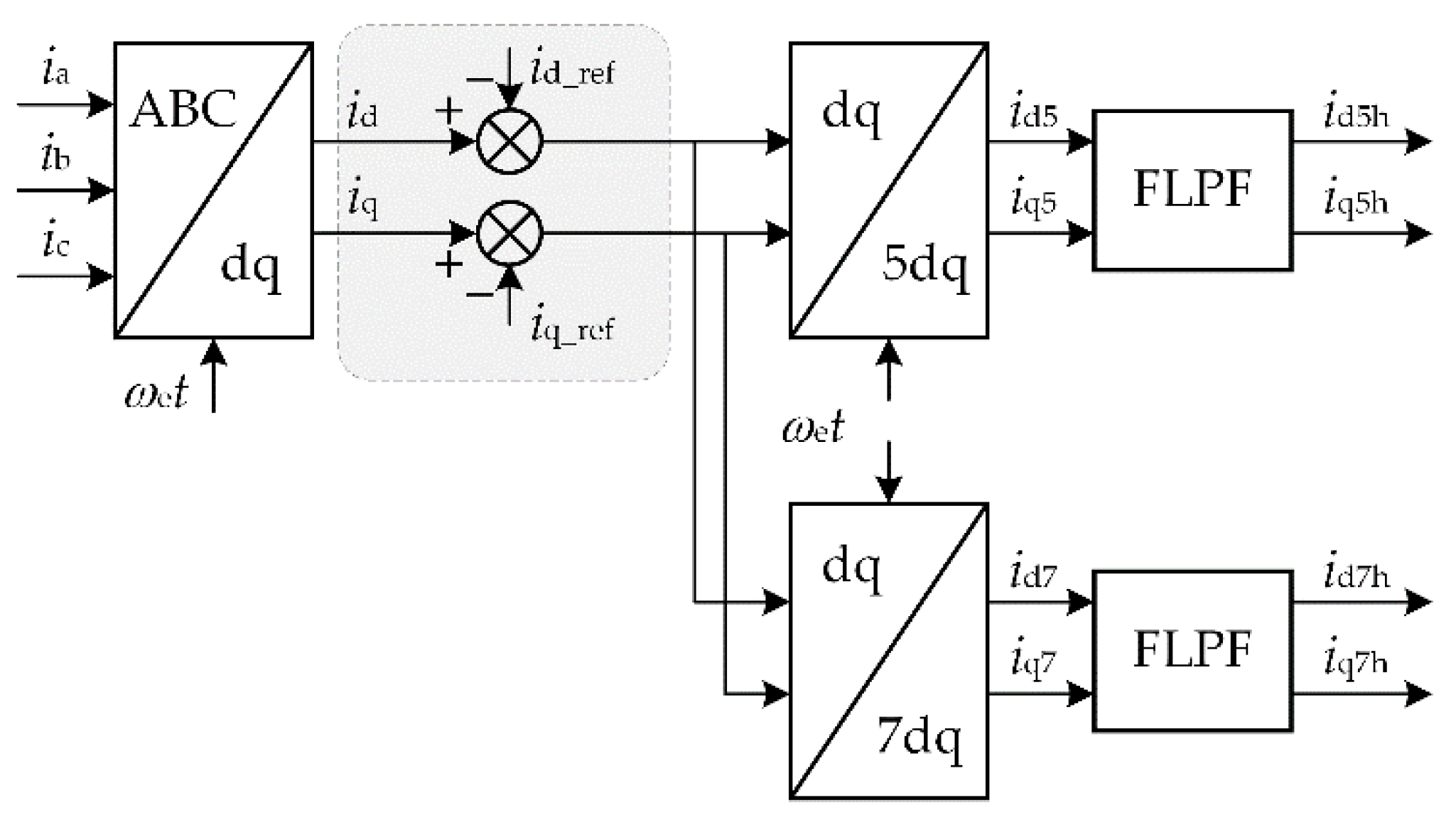
3.1. Improved Current Harmonic Extraction Method
3.1.1. MSFRT
3.1.2. Harmonic Current Extraction Method
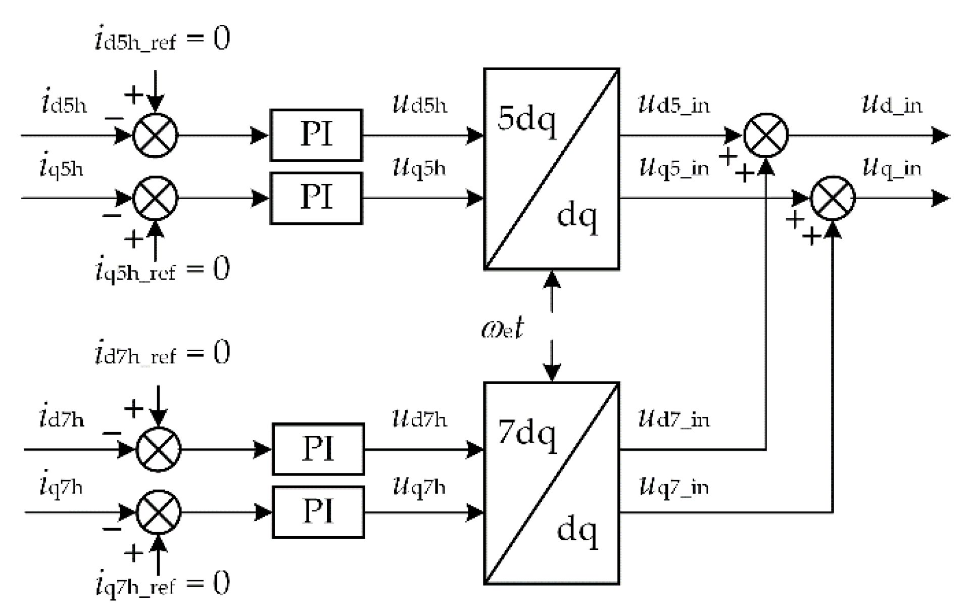
3.2. Traditional Current Harmonic Controller
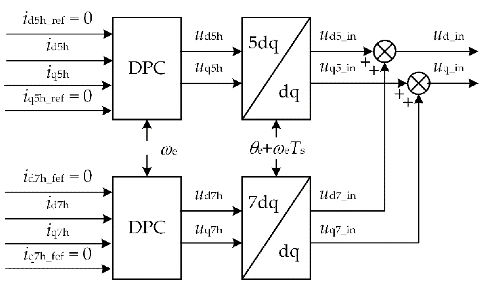
3.3. Improved Current Harmonic Controller
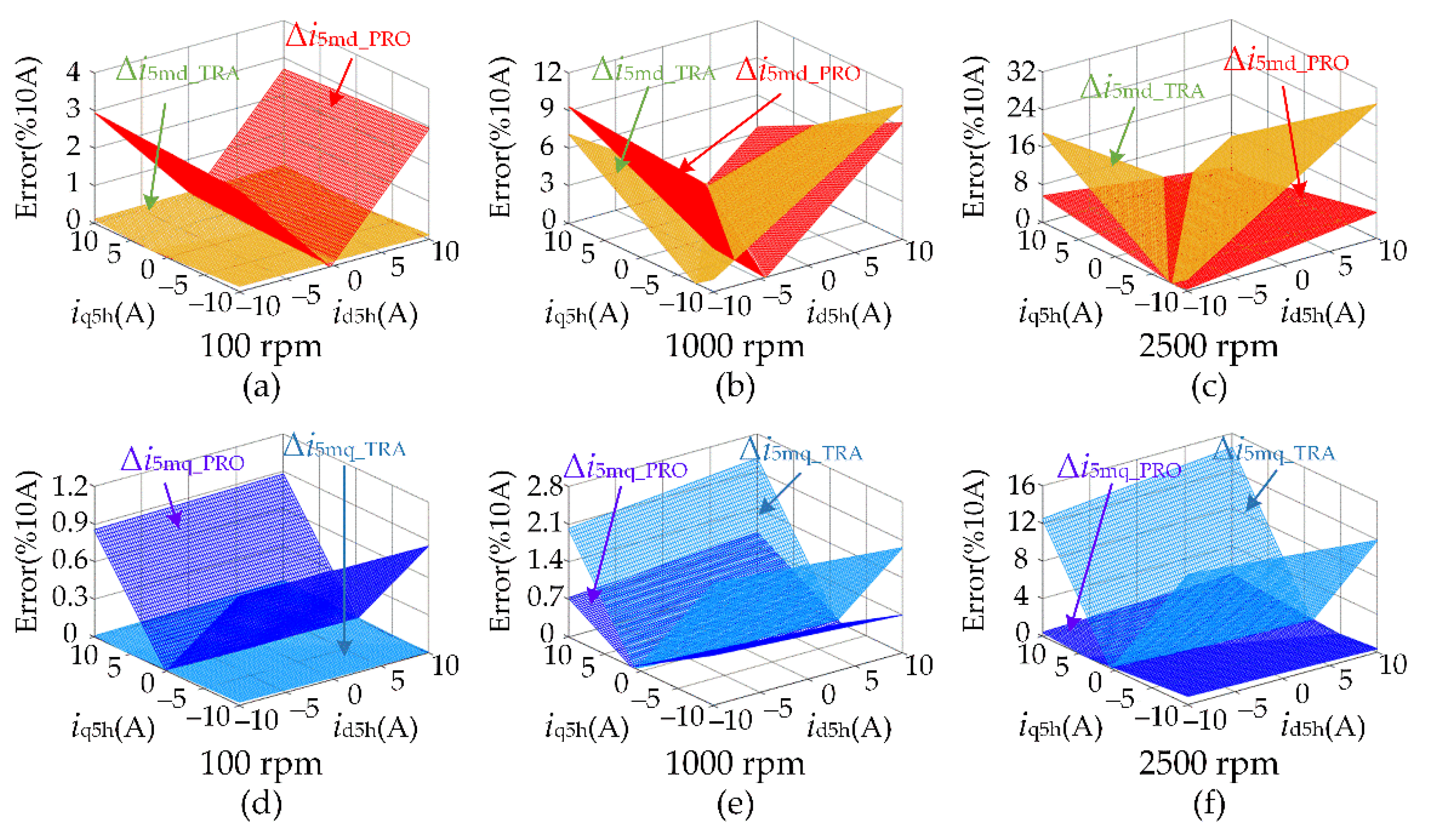
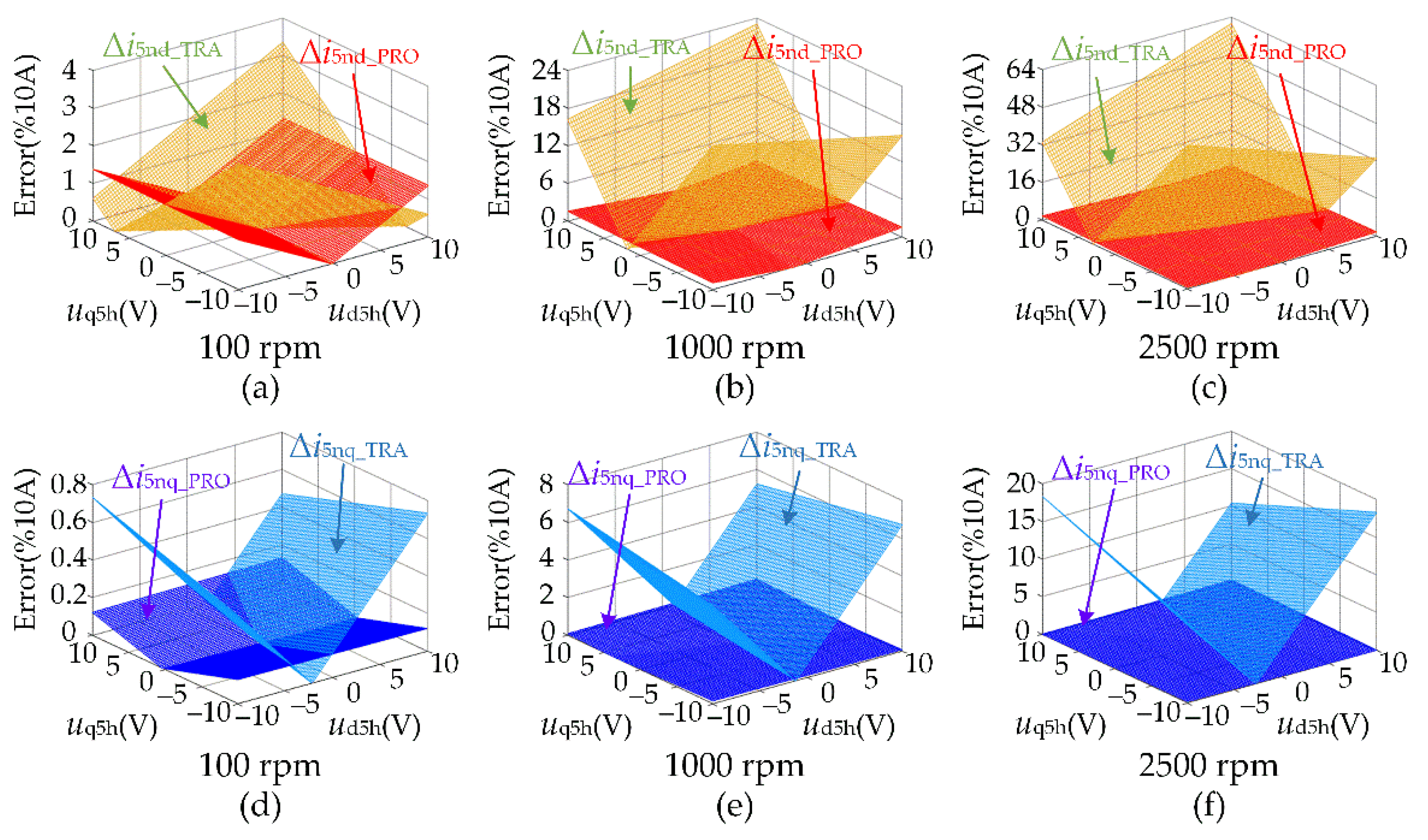
3.3.1. Error Analysis of DPC
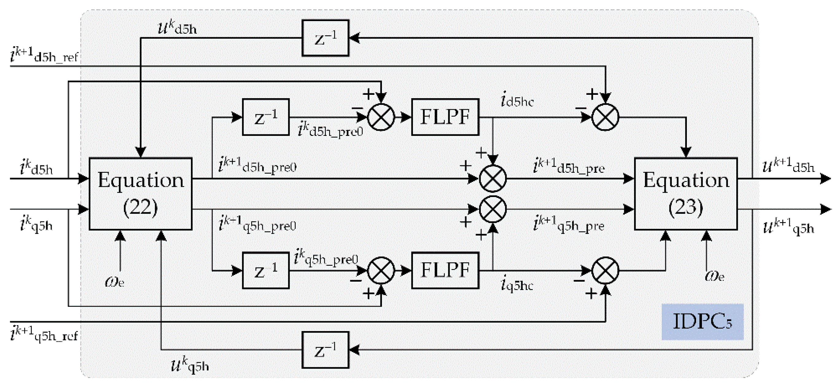
3.3.2. Improved Deadbeat Predictive Control (IDPC)
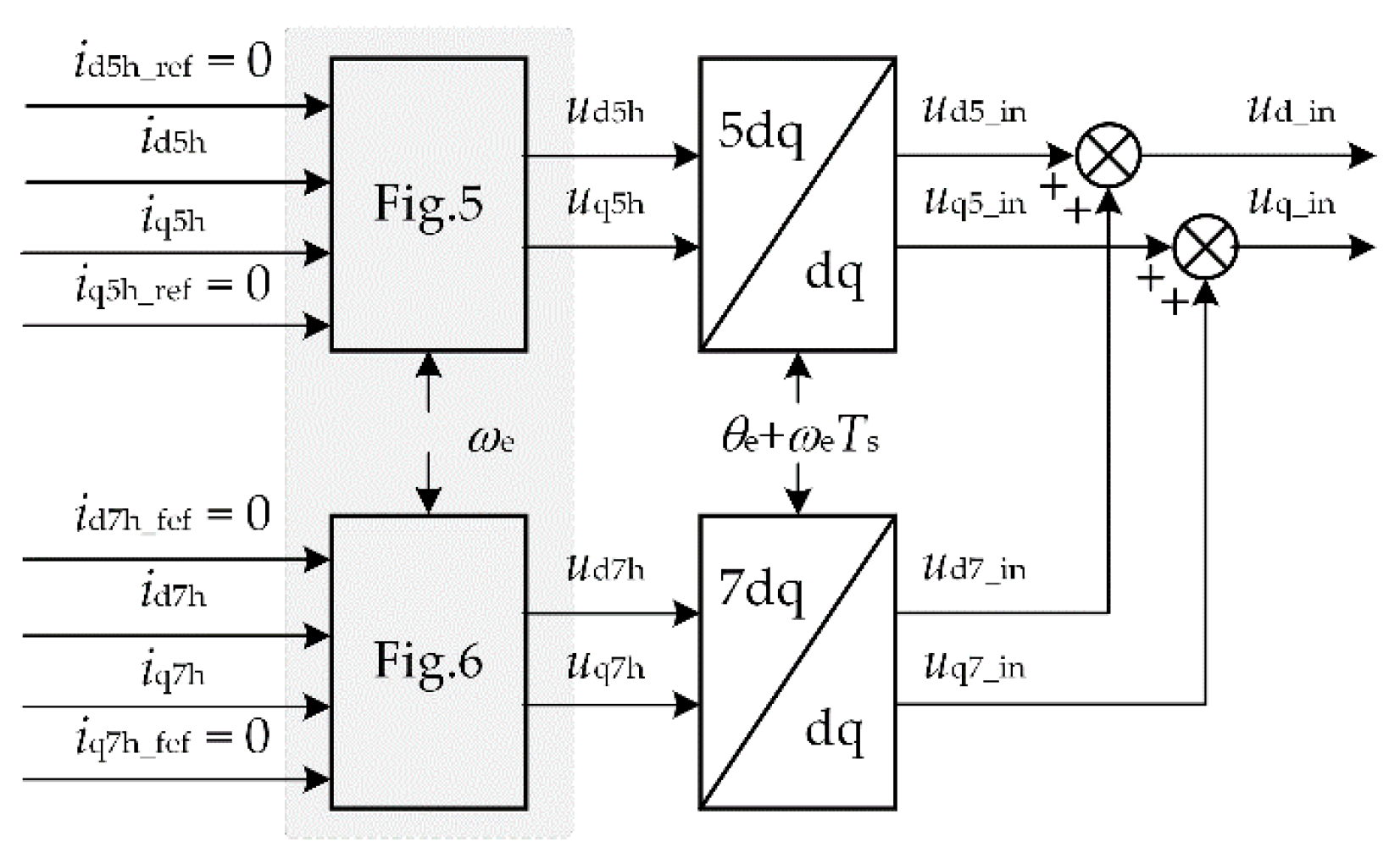
3.3.3. Improved Current Harmonic Controller
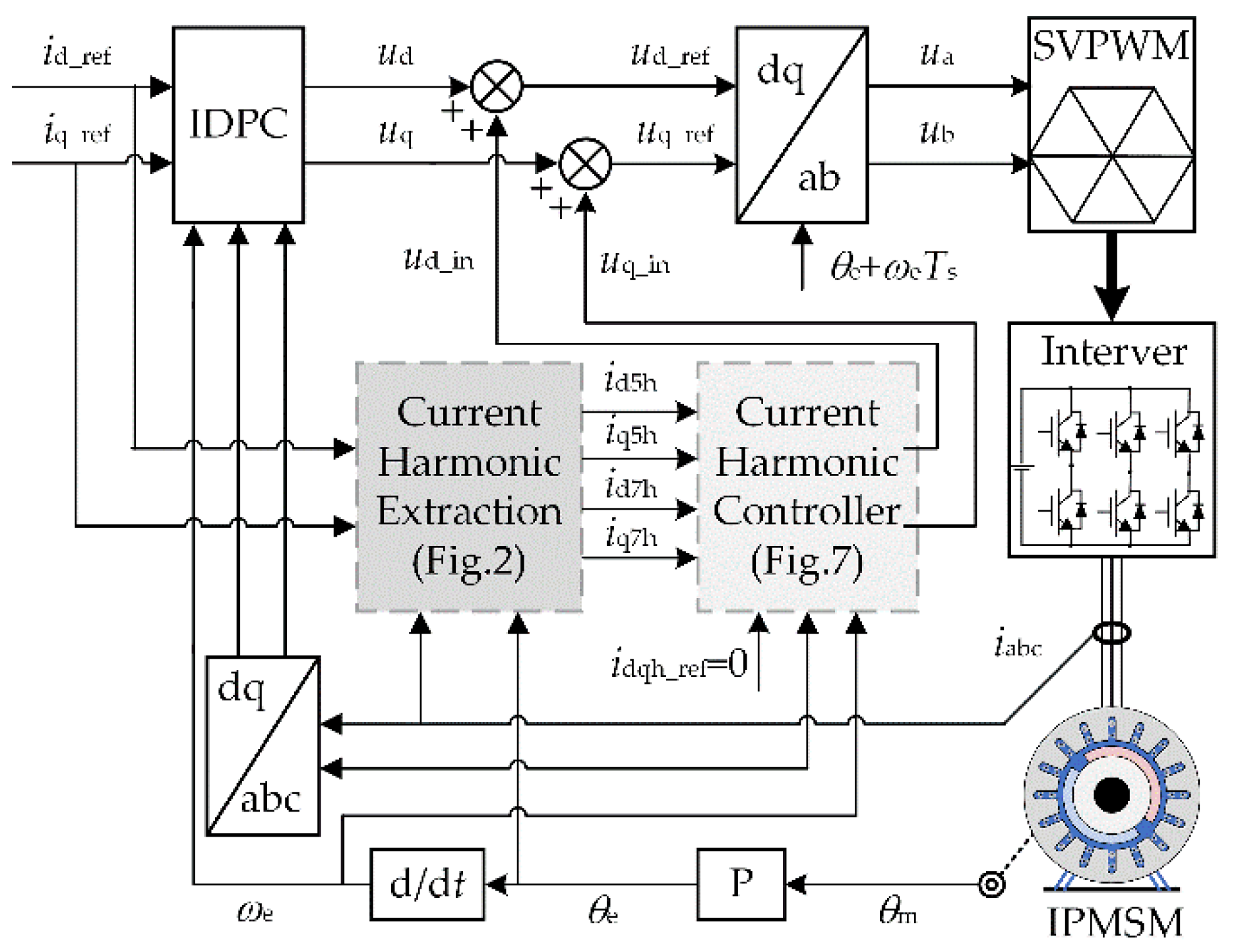
3.4. Proposed Current Harmonic Supression Strategy
4. Simulation and Experimental Results
4.1. Simulation Results of IDPC Method
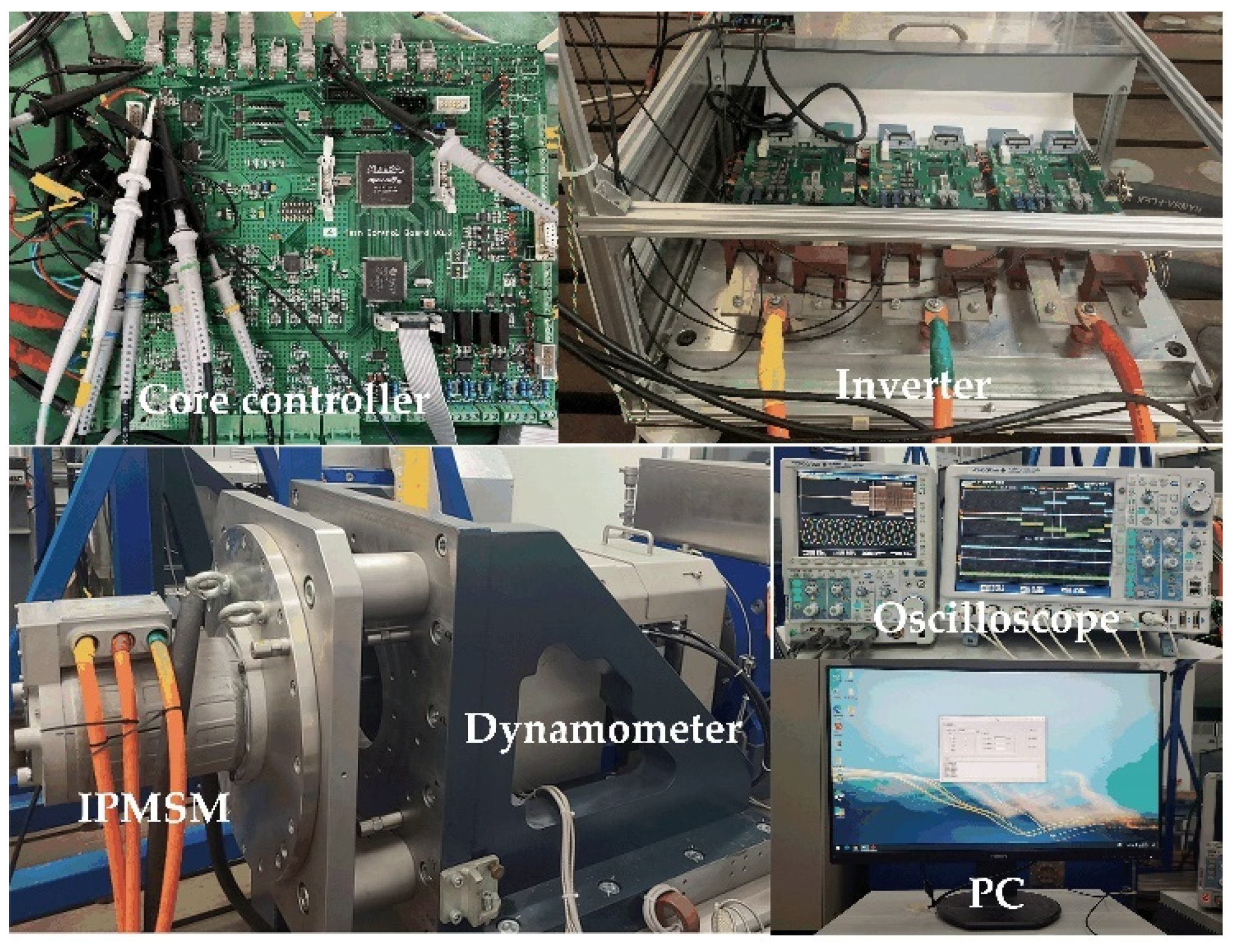
4.2. Experimental Verification of the Proposed Strategy
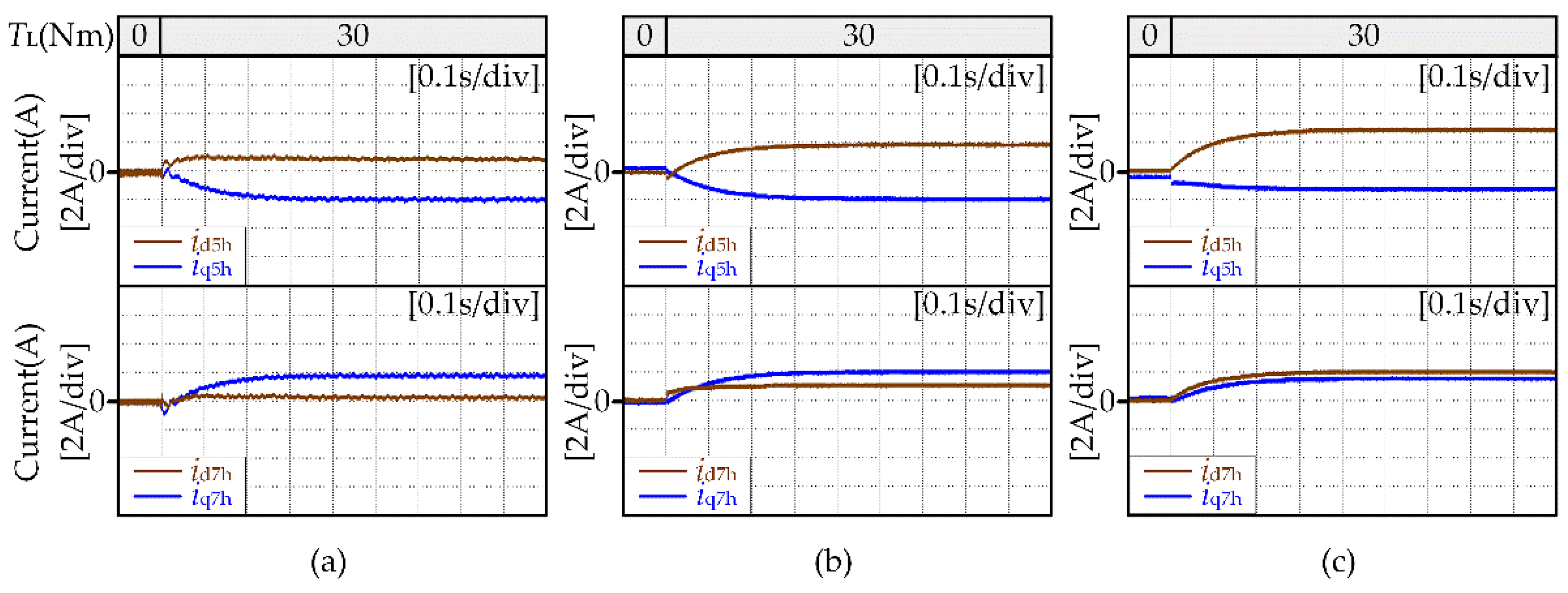
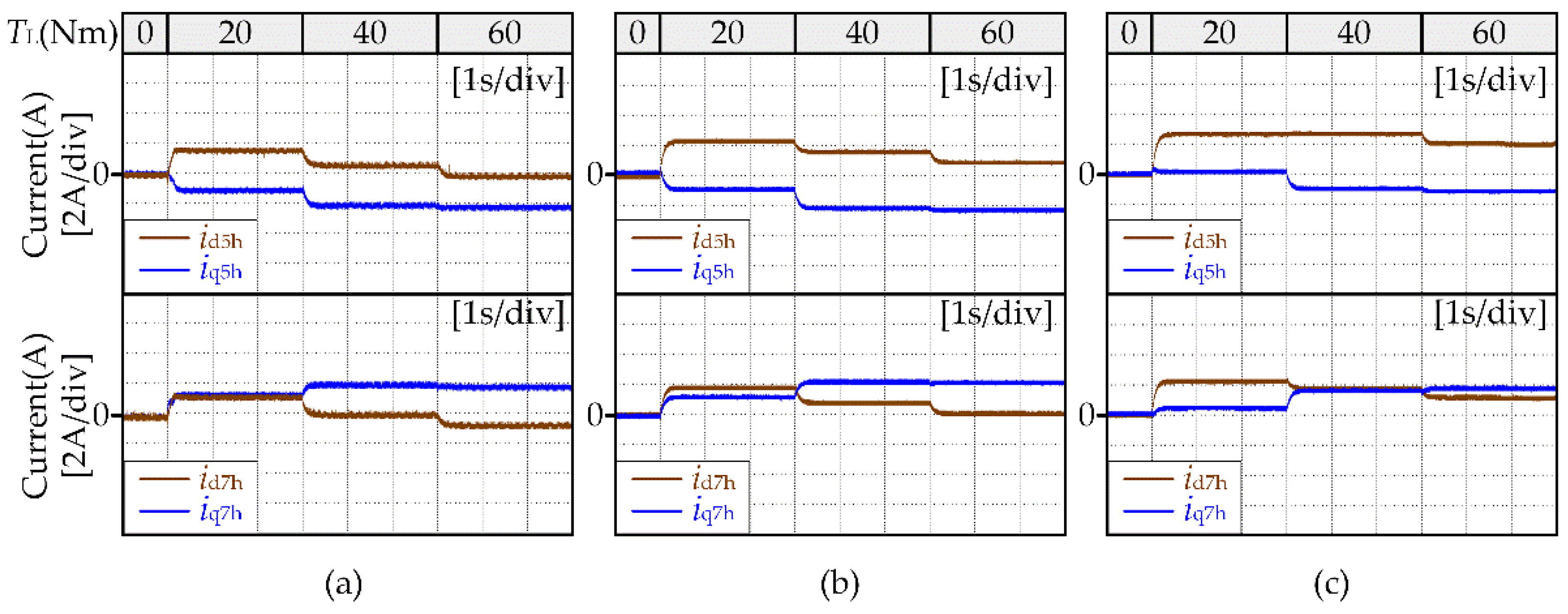
4.2.1. Experimental Results of the Proposed Harmonic Extraction Method
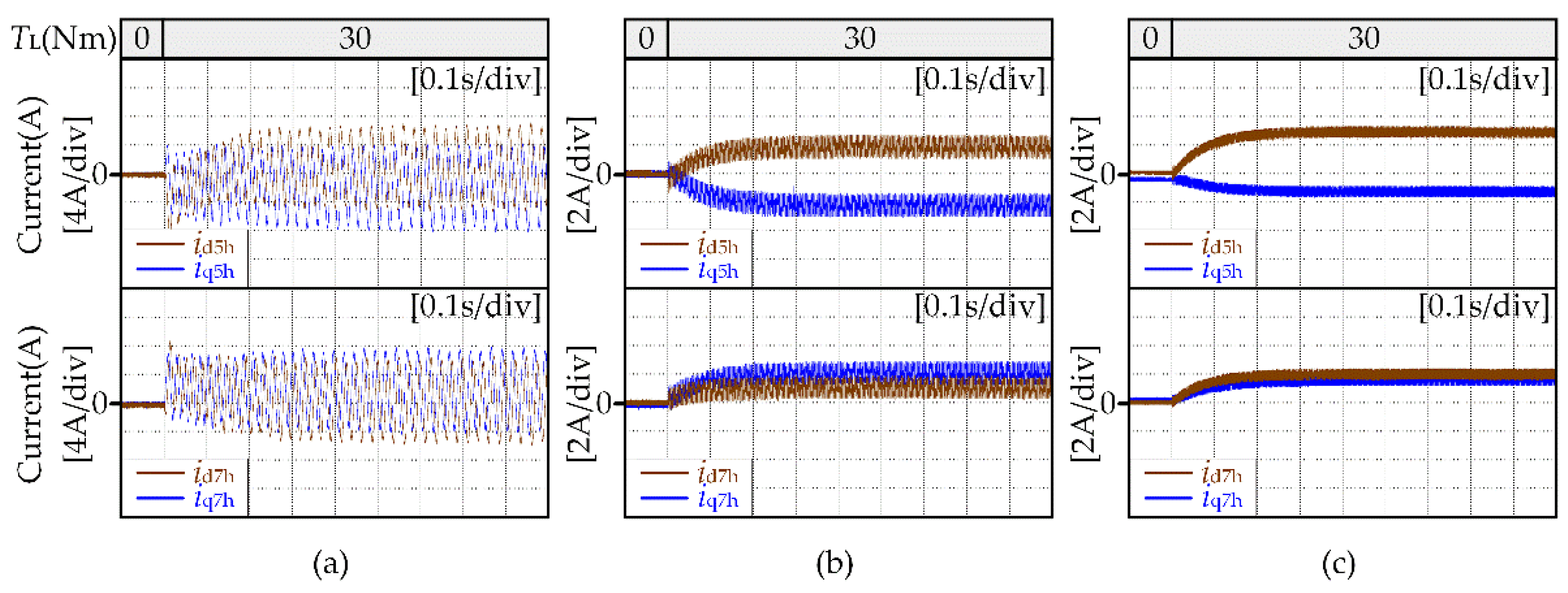
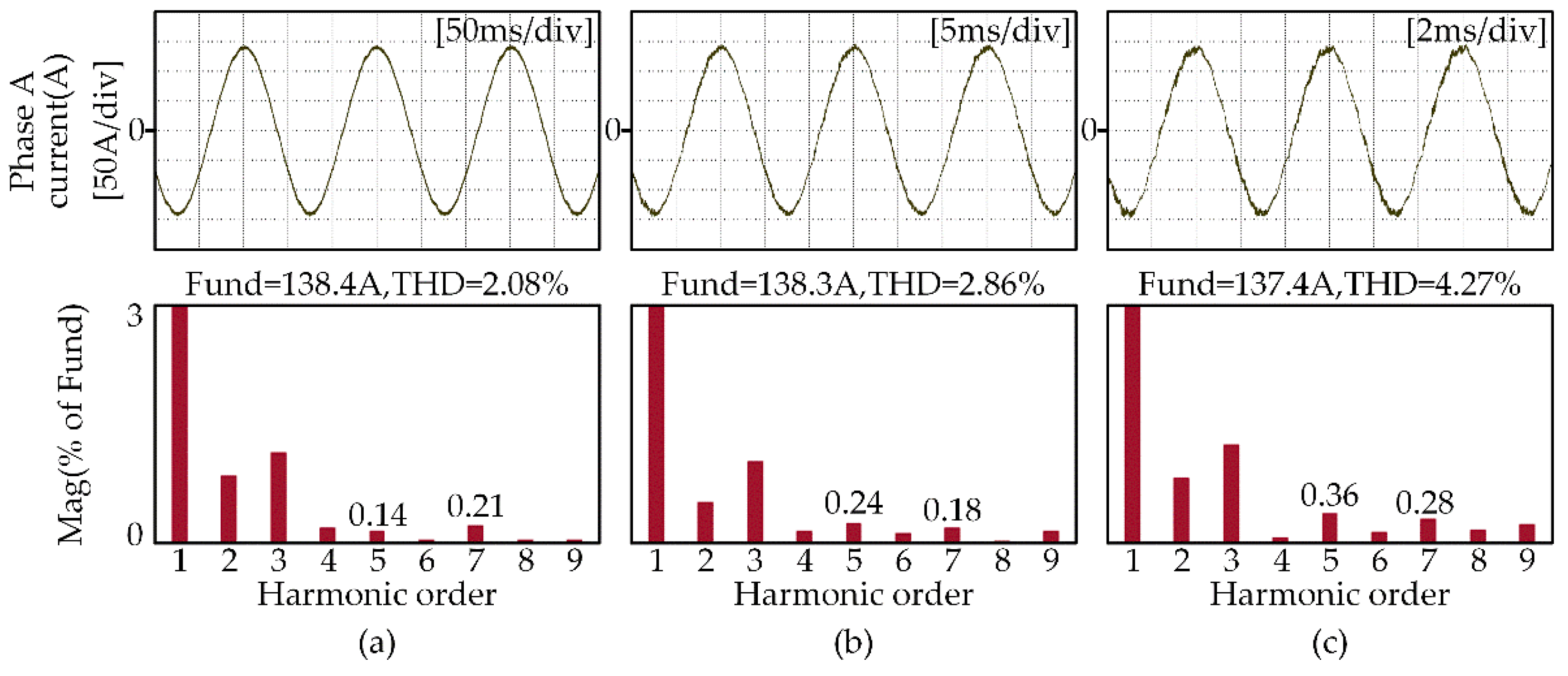
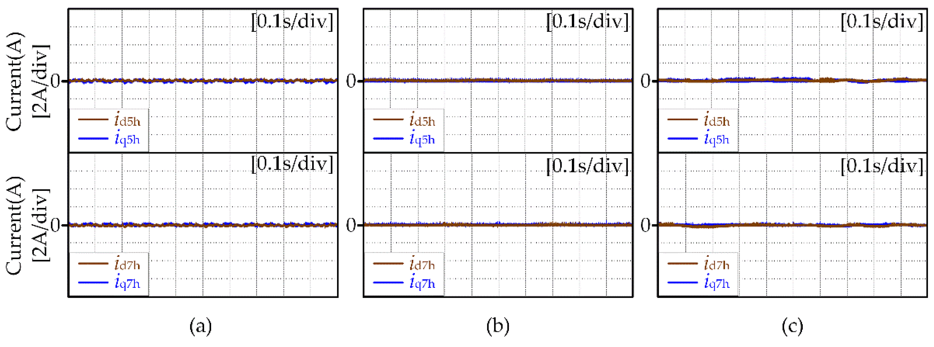
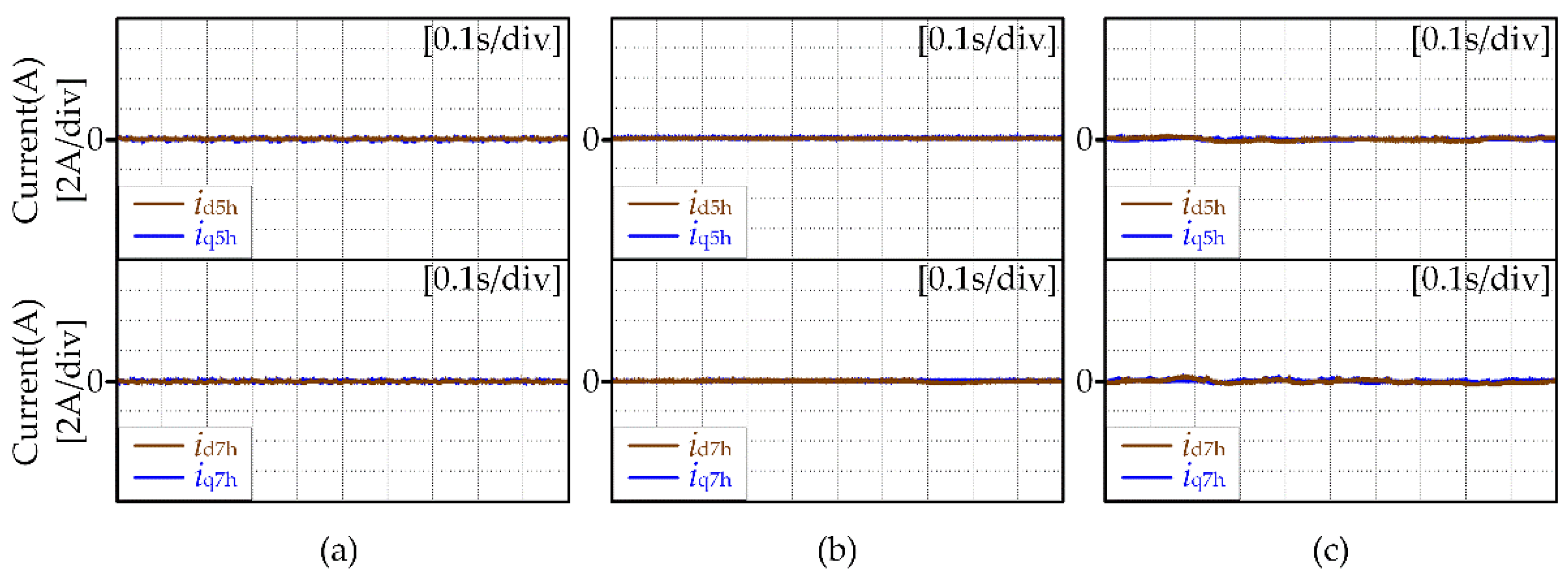
4.2.2. Experimental Results of the Proposed Current Harmonic Suppression Strategy
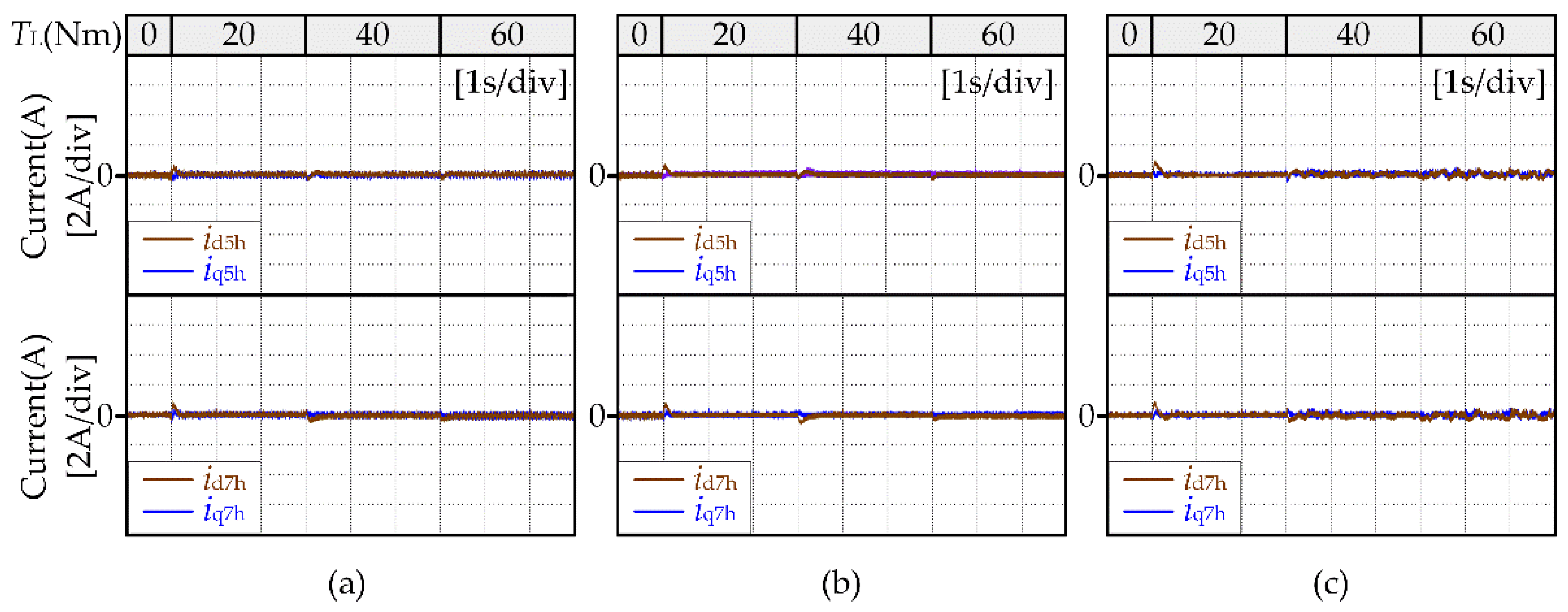
4.2.3. Robustness Experimental of the Proposed Current Harmonic Suppression Strategy
5. Conclusions
- The existing current harmonic extraction method based on MSRFT is improved by reconstructing the input current of the filter. The improved method has a simple structure and can achieve accurate extraction of current harmonics.
- The reason why the DPC based current harmonic controller is difficult to effectively control the current harmonic components is analyzed when the motor speed is high. Additionally, the IDPC based current harmonic controller is proposed by improving the solution method of PMSM state equation and considering the effect of rotor position changes in one control cycle and applying the method of current static error elimination. The proposed controller can effectively control the current harmonic components when the motor speed is high and has strong robustness to moto parameter changes.
- IDPC-based current harmonic suppression strategy is proposed by combining the improved current harmonic extraction method and the IDPC-based current harmonic controller. The experimental results show that the proposed strategy can effectively suppress the 5th and 7th current harmonics when the motor runs at low speed, medium speed and high speed and the controller parameters are mismatched with the motor parameters.
Author Contributions
Funding
Institutional Review Board Statement
Informed Consent Statement
Data Availability Statement
Conflicts of Interest
References
- Chen, Z.; Yan, Y.; Shi, T.; Gu, X.; Wang, Z.; Xia, C. An Accurate Virtual Signal Injection Control for IPMSM with Improved Torque Output and Widen Speed Region. IEEE Trans. Power Electron. 2021, 36, 1941–1953. [Google Scholar] [CrossRef]
- Feng, G.; Lai, C.; Kar, N.C. An Analytical Solution to Optimal Stator Current Design for PMSM Torque Ripple Minimization with Minimal Machine Losses. IEEE Trans. Power Electron. 2017, 64, 7655–7665. [Google Scholar] [CrossRef]
- Yi, P.; Wang, X.; Sun, Z. Instantaneous harmonic decomposition technique for three-phase current based on multiple reference coordinates. IET Electr. Power Appl. 2018, 12, 547–556. [Google Scholar] [CrossRef]
- Feng, G.; Lai, C.; Li, W.; Li, Z.; Kar, N.C. Dual Reference Frame Based Current Harmonic Minimization for Dual Three-Phase PMSM Considering Inverter Voltage Limit. IEEE Trans. Power Electron. 2021, 36, 8055–8066. [Google Scholar] [CrossRef]
- Feng, G.; Lai, C.; Tian, J.; Kar, N.C. Multiple Reference Frame Based Torque Ripple Minimization for PMSM Drive Under Both Steady-State and Transient Conditions. IEEE Trans. Power Electron. 2019, 34, 6685–6696. [Google Scholar] [CrossRef]
- Wang, W.; Liu, C.; Liu, S.; Song, Z.; Zhao, H.; Dai, B. Current Harmonic Suppression for Permanent-Magnet Synchronous Motor Based on Chebyshev Filter and PI Controller. IEEE Trans. Magn. 2021, 57, 2. [Google Scholar] [CrossRef]
- Liu, G.; Chen, B.; Wang, K.; Song, X. Selective Current Harmonic Suppression for High-Speed PMSM Based on High-Precision Harmonic Detection Method. IEEE Trans. Ind. Inform. 2019, 15, 3457–3468. [Google Scholar] [CrossRef]
- Lai, C.; Feng, G.; Kar, N.C. Torque Ripple Modeling and Minimization for Interior PMSM Considering Magnetic Saturation. IEEE Trans. Power Electron. 2018, 33, 2417–2429. [Google Scholar] [CrossRef]
- Qu, J.; Jatskevich, J.; Zhang, C.; Zhang, S. Torque Ripple Reduction Method for Permanent Magnet Synchronous Machine Drives with Novel Harmonic Current Control. IEEE Trans. Energy Convers. 2021, 36, 2502–2513. [Google Scholar] [CrossRef]
- Tang, Z.; Akin, B. A New LMS Algorithm Based Deadtime Compensation Method for PMSM FOC Drives. IEEE Trans. Ind. Appl. 2018, 54, 6472–6484. [Google Scholar] [CrossRef]
- Chen, Z.; Zhang, X.; Liu, C.; Zhang, H.; Luo, G. Research on Current Decoupling and Harmonic Suppression Strategy of Permanent Magnet Synchronous Motor by Proportional Resonance Adaptive Disturbance Rejection Control. Proc. CSEE 2021. [Google Scholar] [CrossRef]
- Wang, H.; Xia, C.; Yan, Y.; Shi, T. Harmonic suppression of current in flux weakening region of surface mounted permanent magnet synchronous motor based on resonance control. Trans. CES 2014, 29, 84–91. [Google Scholar]
- Mai, Z.; Xiao, F.; Liu, J.; Zhang, W.; Lian, C. Harmonic Current Suppression Strategy of Dual Three-Phase Permanent Magnet Synchronous Motor Based on Quasi Proportional Resonant Cascading PI. Trans. CES 2018, 33, 5751–5759. [Google Scholar]
- Tang, Z.; Akin, B. Suppression of Dead-Time Distortion Through Revised Repetitive Controller in PMSM Drives. IEEE Trans. Energy Convers. 2017, 32, 918–930. [Google Scholar] [CrossRef]
- Deng, W.; Xia, C.; Yan, Y.; Geng, Q.; Shi, T. Online Multiparameter Identification of Surface-Mounted PMSM Considering Inverter Disturbance Voltage. IEEE Trans. Energy Convers. 2017, 32, 202–212. [Google Scholar] [CrossRef]
- Zhong, Z.; Jiang, S.; Jin, S.; Chen, X.; Zhou, Y. Study on harmonic Voltage and current of permanent magnet synchronous motor Coupling model and feedforward control. Trans. CES 2017, 32, 131–142. [Google Scholar]
- Wu, Z.; Yang, Z.; Ding, K.; He, G. Transfer Mechanism Analysis of Injected Voltage Harmonic and its Effect on Current Harmonic Regulation in FOC PMSM. IEEE Trans. Power Electron. 2022, 37, 820–829. [Google Scholar] [CrossRef]
- Kim, H.; Han, Y.; Lee, K.; Bhattacharya, S. A Sinusoidal Current Control Strategy Based on Harmonic Voltage Injection for Harmonic Loss Reduction of PMSMs with Non-Sinusoidal Back-EMF. IEEE Trans. Ind. Appl. 2020, 56, 7032–7043. [Google Scholar] [CrossRef]
- Chen, Z.; Shi, T.; Lin, Z.; Wang, Z.; Gu, X. Analysis and Control of Current Harmonic in IPMSM Field-Oriented Control System. IEEE Trans. Power Electron. 2022, 37, 9571–9585. [Google Scholar] [CrossRef]
- Sun, J.; Wang, Z.; Gu, X.; Xia, C. Predictive Current Control of PMSM with High-Speed and Low-frequency Ratio. Proc. CSEE 2020, 40, 3663–3672. [Google Scholar]


| Parameters | Symbol | Value |
|---|---|---|
| Rated voltage | UN | 320 V |
| Rated current | IN | 180 A |
| Rated speed | n | 3000 rpm |
| Rated torque | TN | 72 Nm |
| Pole pairs | p | 4 |
| Stator resistance | R | 0.03 Ω |
| D-axis inductance | Ld | 0.1049 mH |
| Q-axis inductance | Lq | 0.3453 mH |
| PM fundamental flux linkage | ψf | 0.038749 Wb |
| PM 5th harmonic flux linkage | ψf5 | 0.0003771 Wb |
| PM 7th harmonic flux linkage | ψf7 | 0.0004135 Wb |
Publisher’s Note: MDPI stays neutral with regard to jurisdictional claims in published maps and institutional affiliations. |
© 2022 by the authors. Licensee MDPI, Basel, Switzerland. This article is an open access article distributed under the terms and conditions of the Creative Commons Attribution (CC BY) license (https://creativecommons.org/licenses/by/4.0/).
Share and Cite
Gu, X.; Li, Y.; Chen, W.; Jin, X. Improved Deadbeat Predictive Control Based Current Harmonic Suppression Strategy for IPMSM. Energies 2022, 15, 3943. https://doi.org/10.3390/en15113943
Gu X, Li Y, Chen W, Jin X. Improved Deadbeat Predictive Control Based Current Harmonic Suppression Strategy for IPMSM. Energies. 2022; 15(11):3943. https://doi.org/10.3390/en15113943
Chicago/Turabian StyleGu, Xin, Yiyang Li, Wei Chen, and Xuefeng Jin. 2022. "Improved Deadbeat Predictive Control Based Current Harmonic Suppression Strategy for IPMSM" Energies 15, no. 11: 3943. https://doi.org/10.3390/en15113943
APA StyleGu, X., Li, Y., Chen, W., & Jin, X. (2022). Improved Deadbeat Predictive Control Based Current Harmonic Suppression Strategy for IPMSM. Energies, 15(11), 3943. https://doi.org/10.3390/en15113943