
A Study on the Improvement of Torque Density of an Axial Slot-Less Flux Permanent Magnet Synchronous Motor for Collaborative Robot


Abstract
:1. Introduction
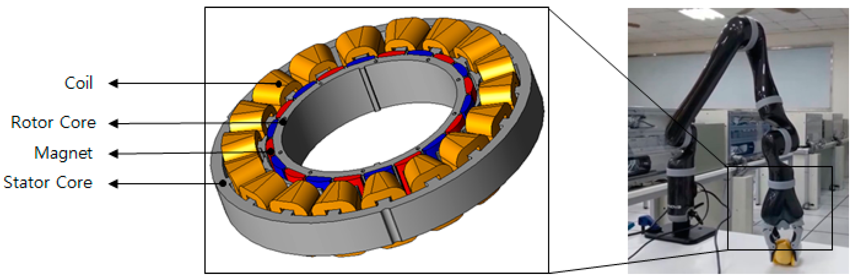
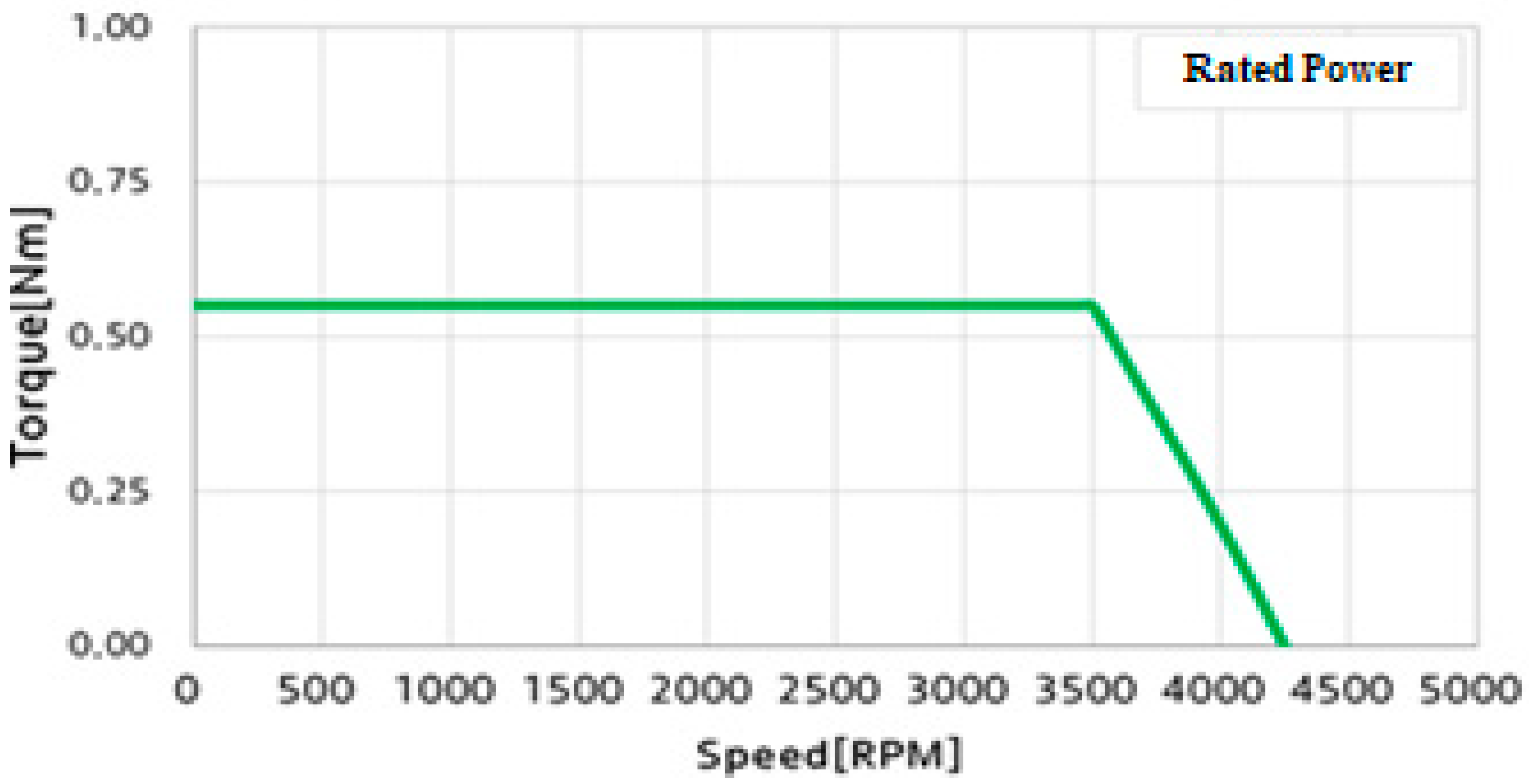
2. Target Model Specification
3. ASFPMSM Proposal Model Concept
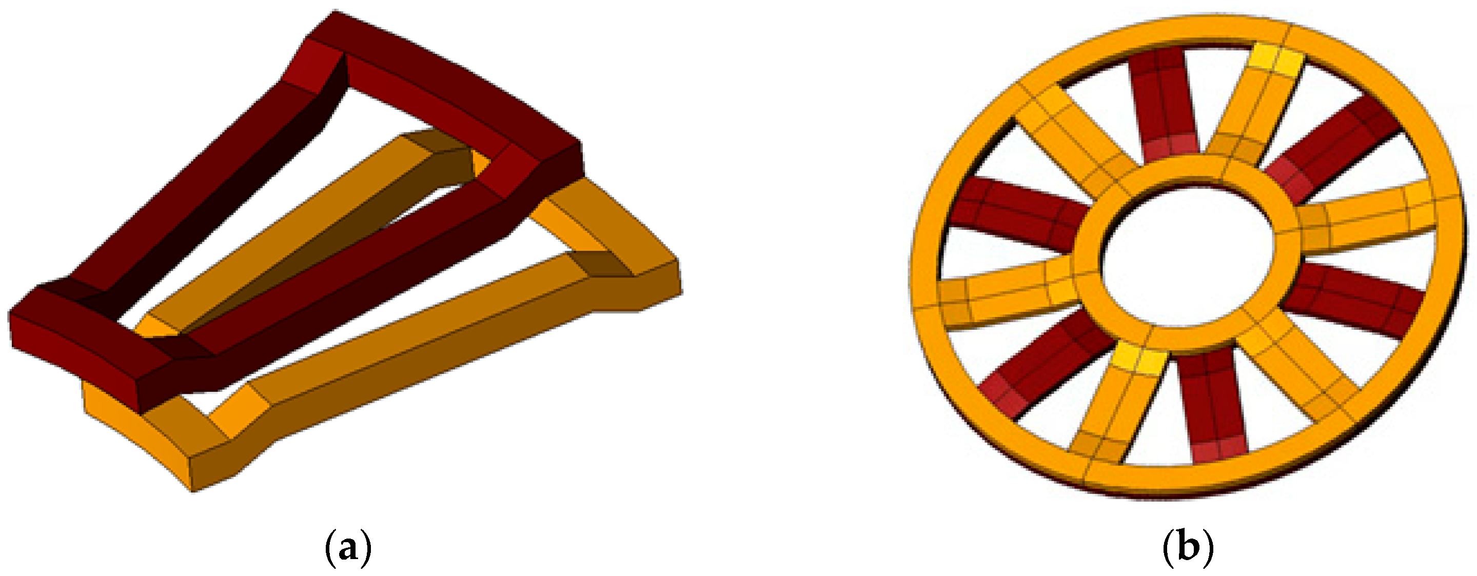
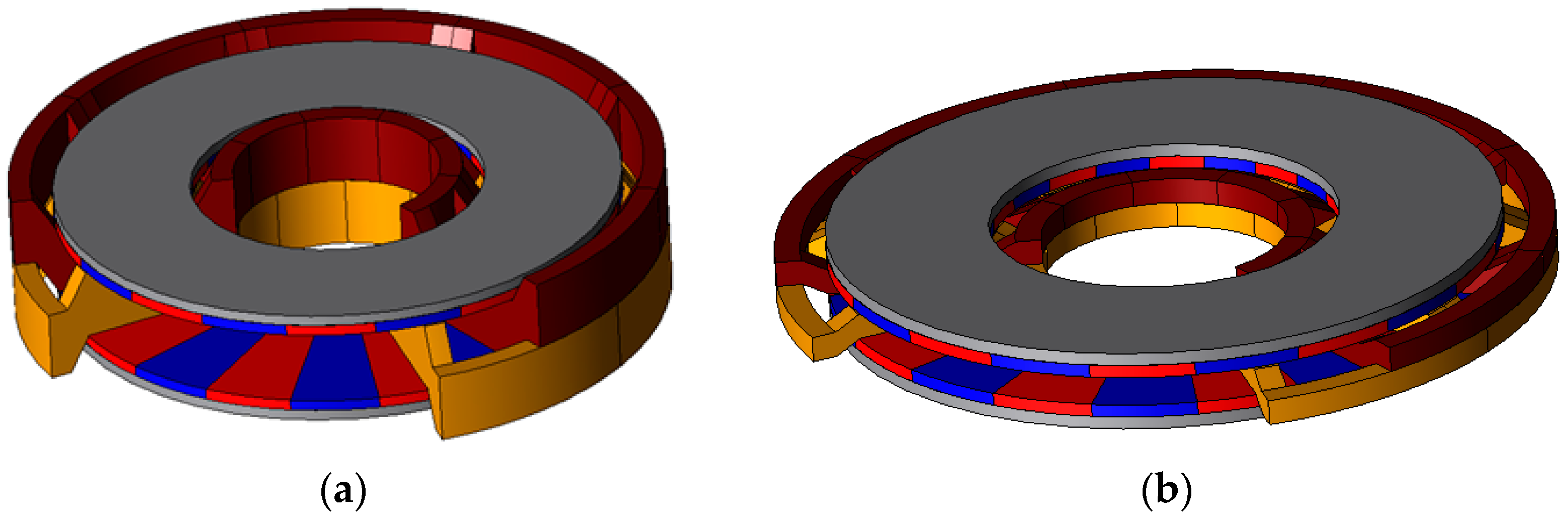
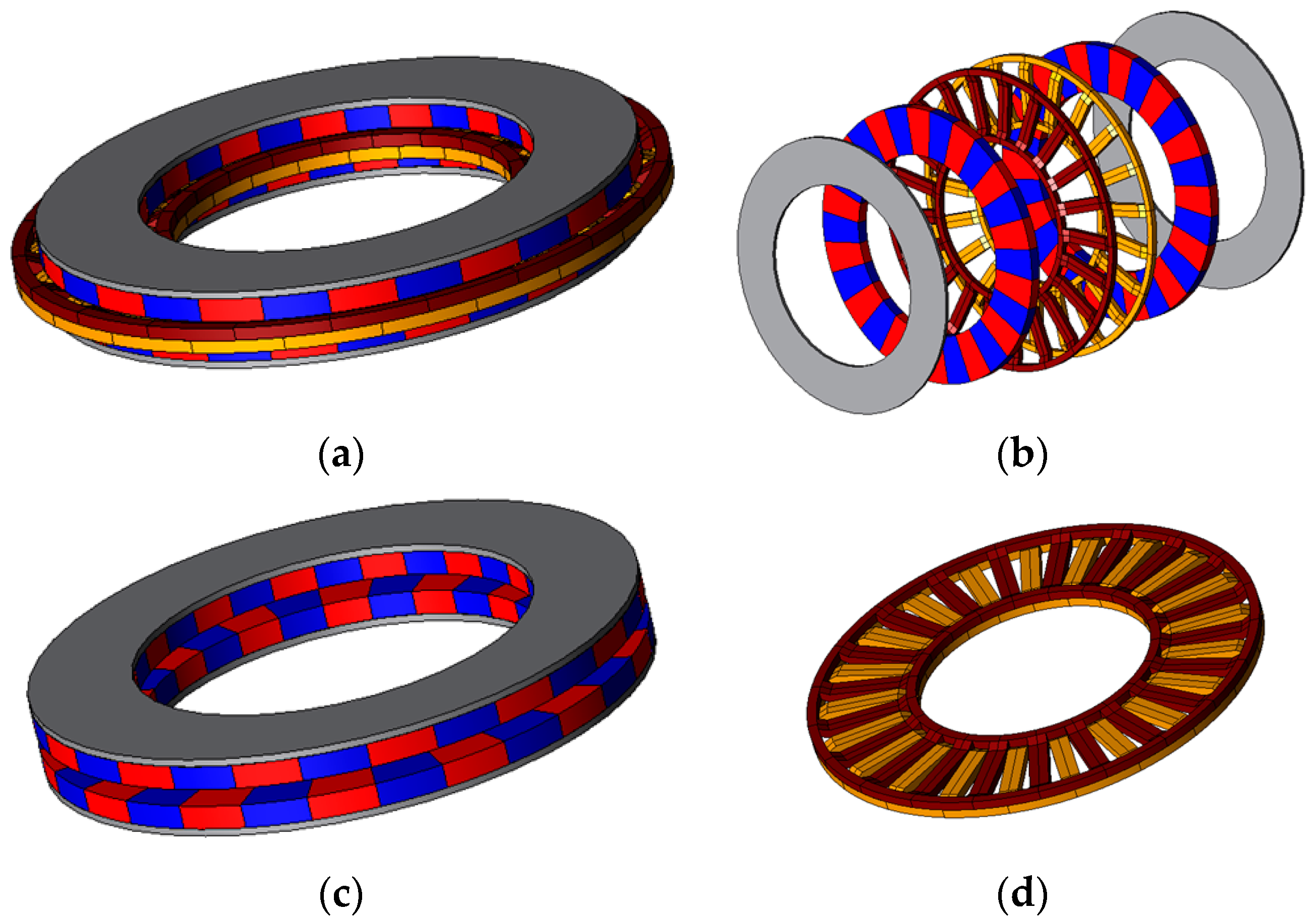
3.1. Proposed ASFPMSM Concept
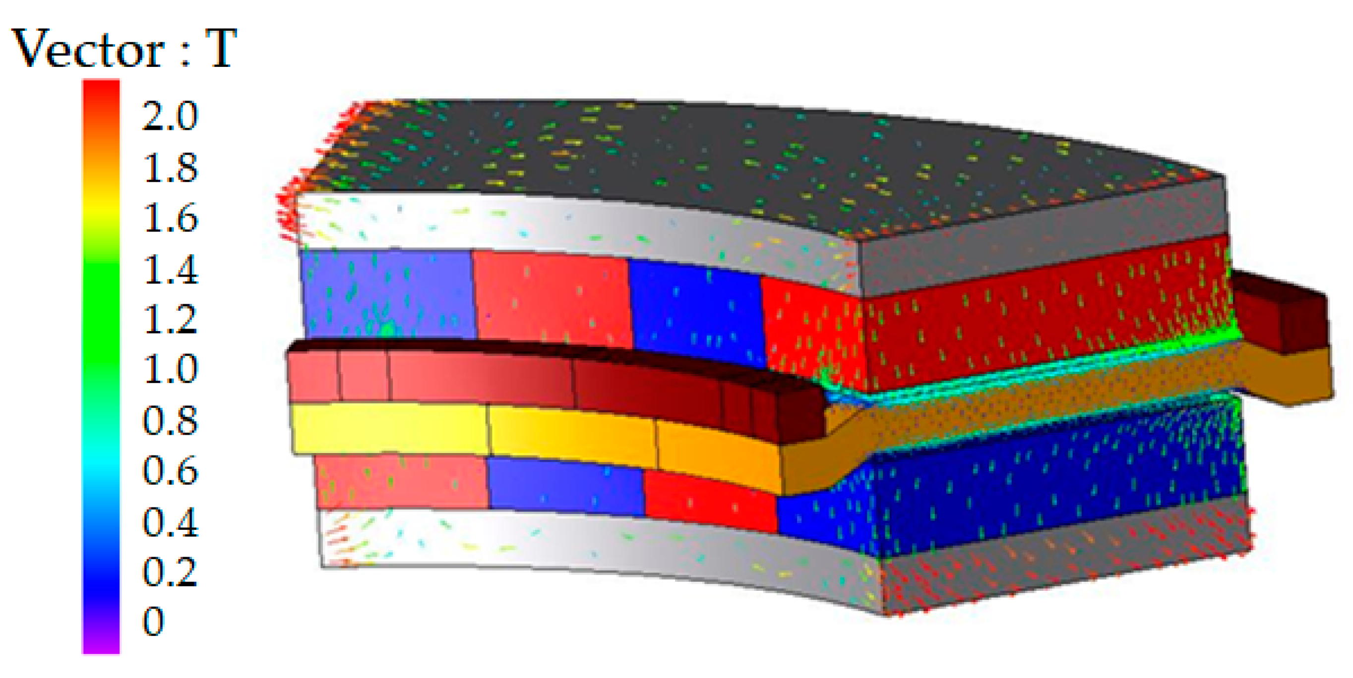
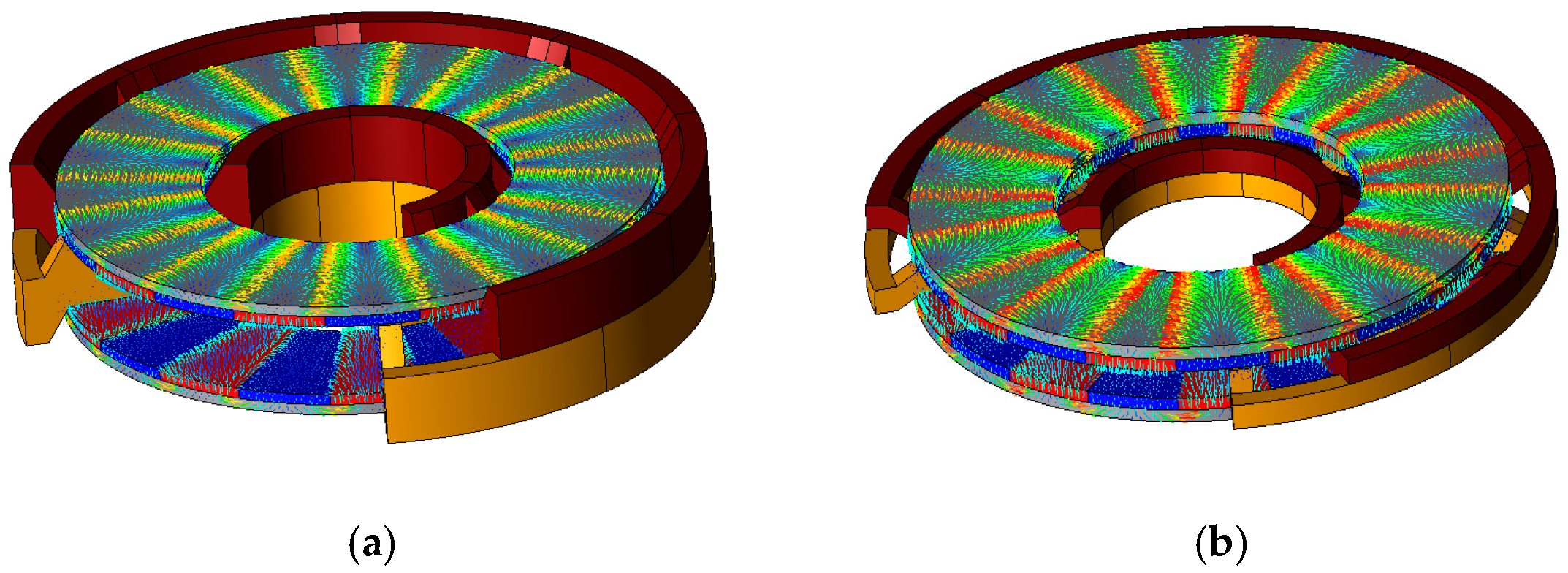
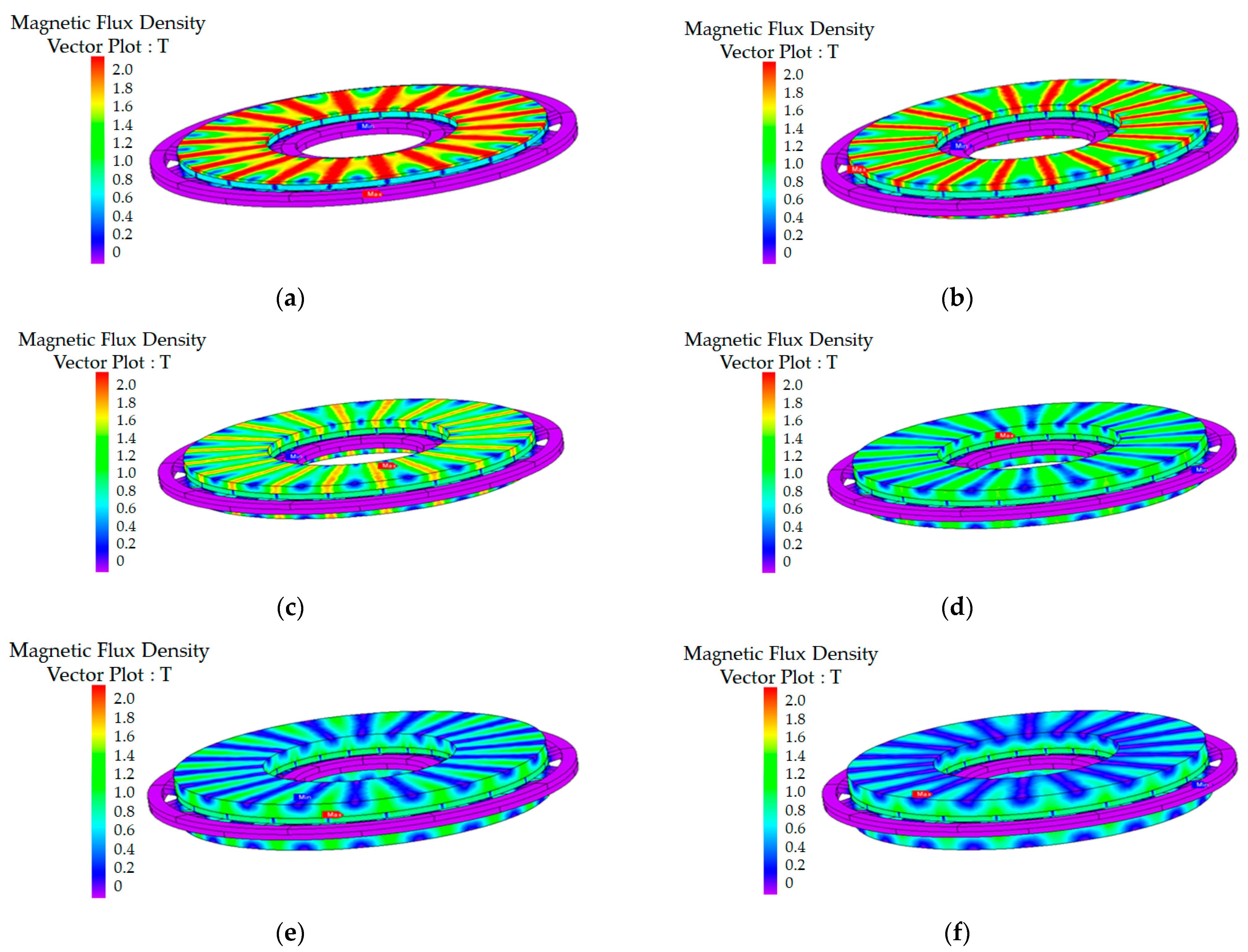
3.2. Analysis of Proposed ASFPMSM
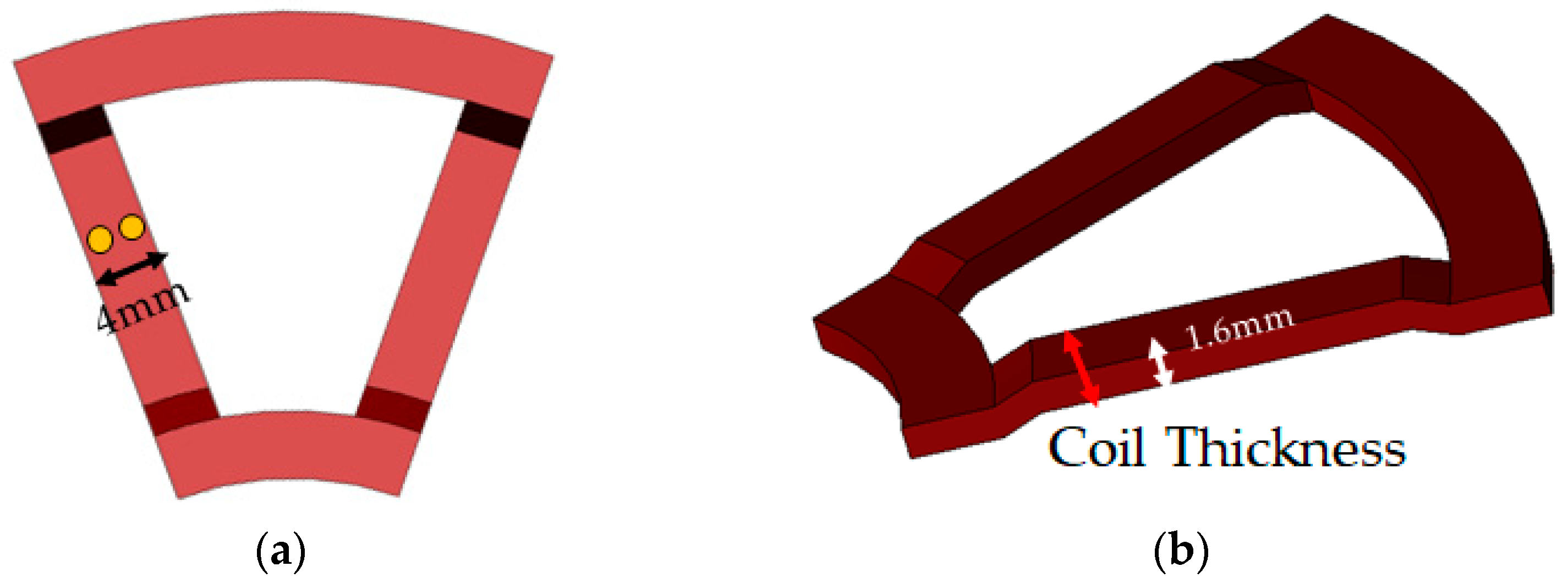
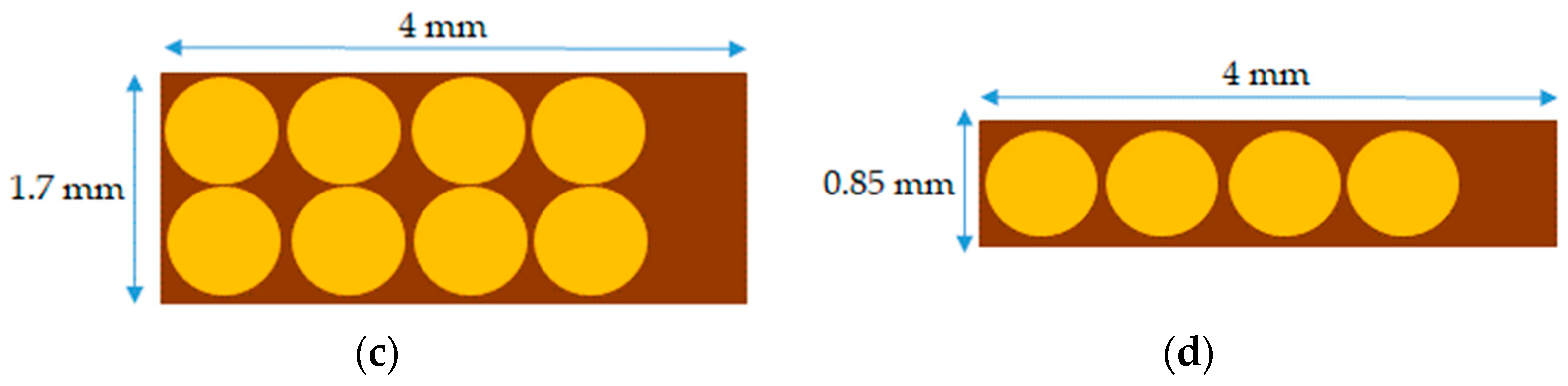
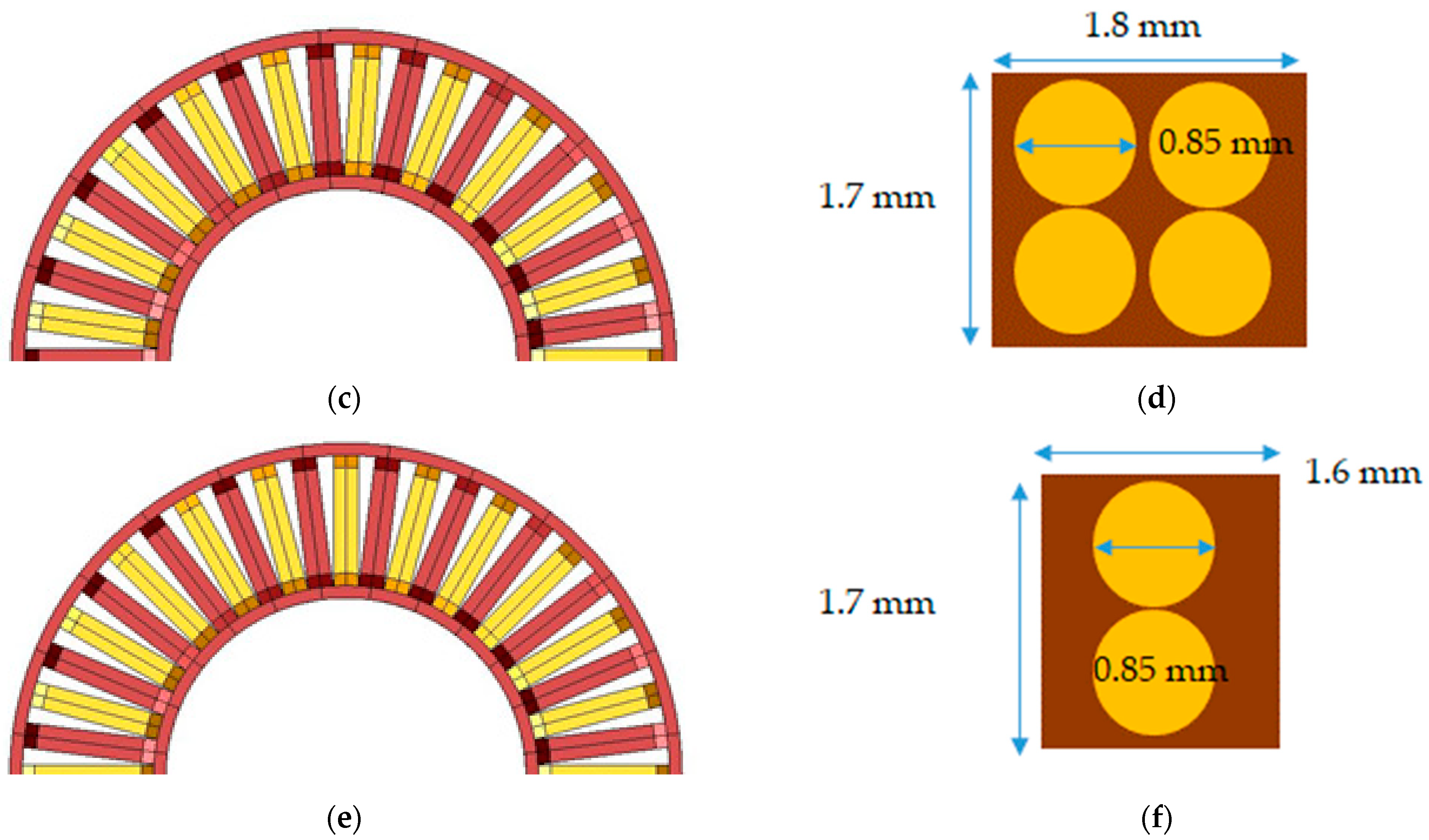
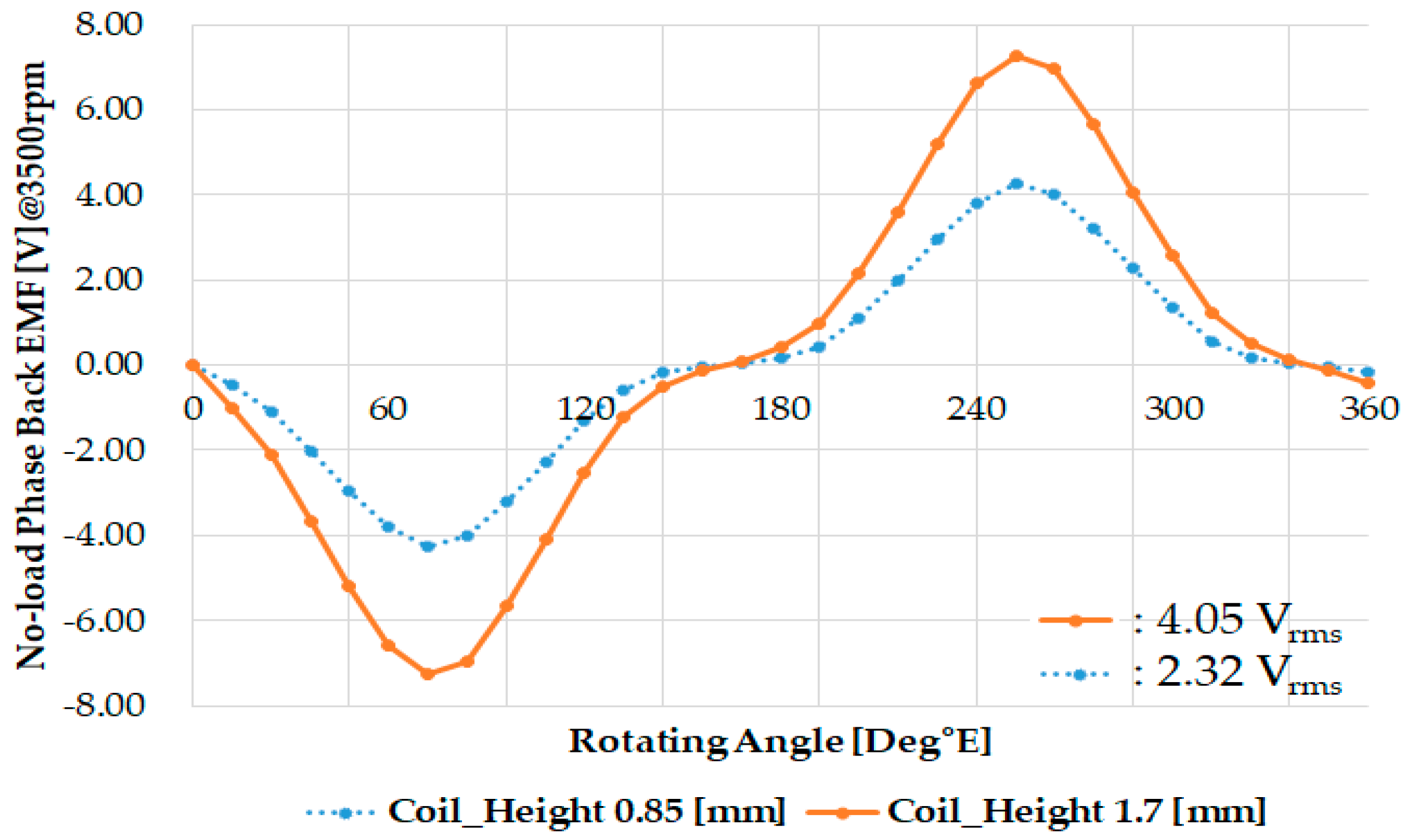
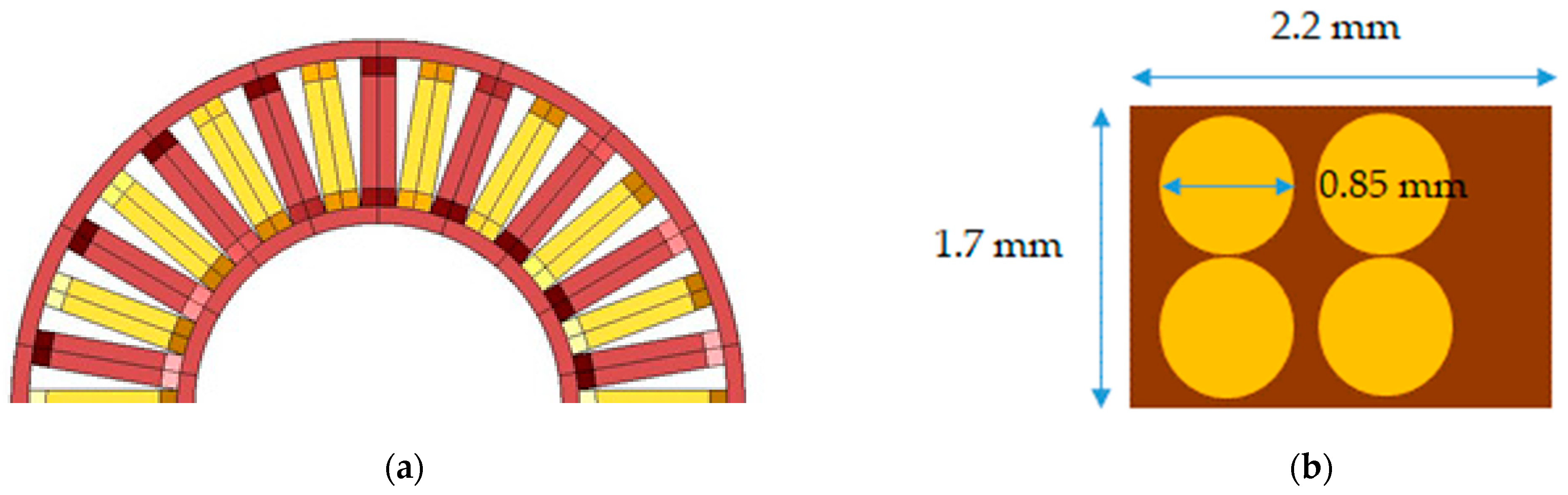
3.3. ASFPMSM Optimal Coil Height Analysis
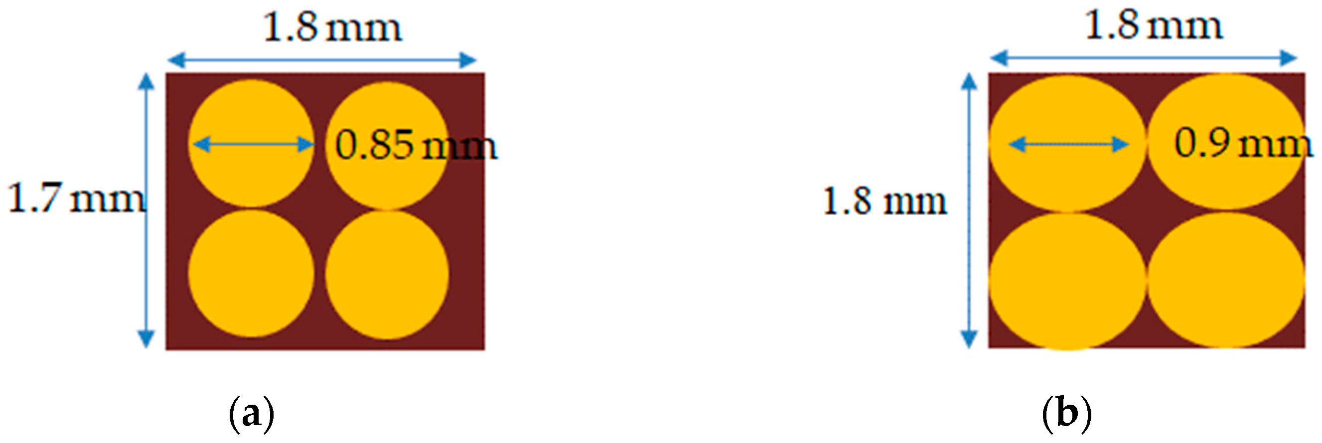
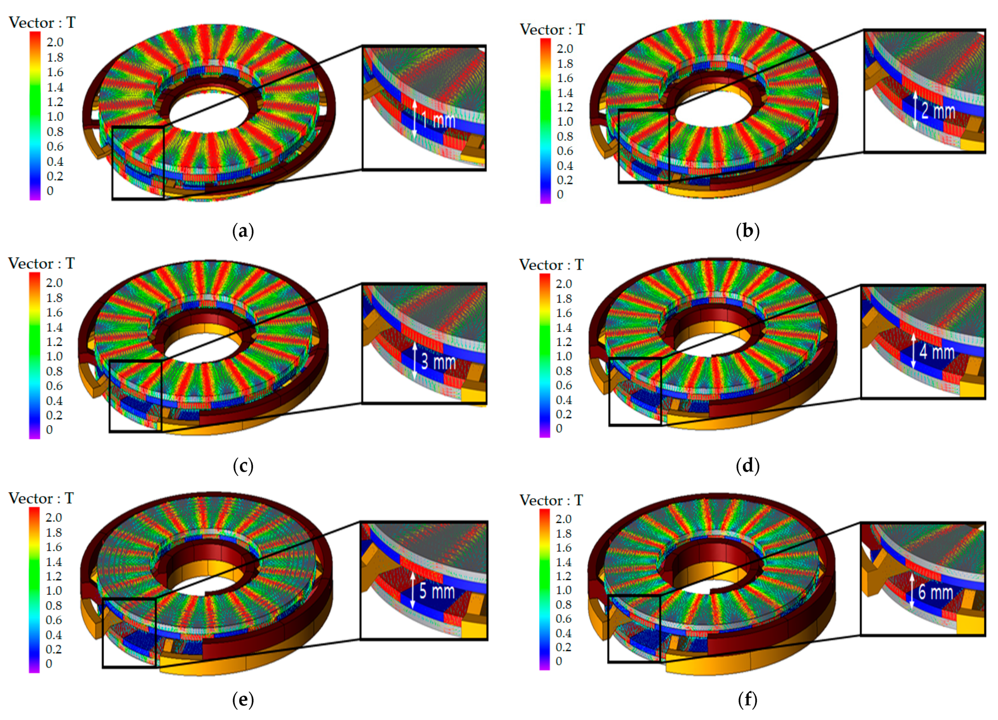
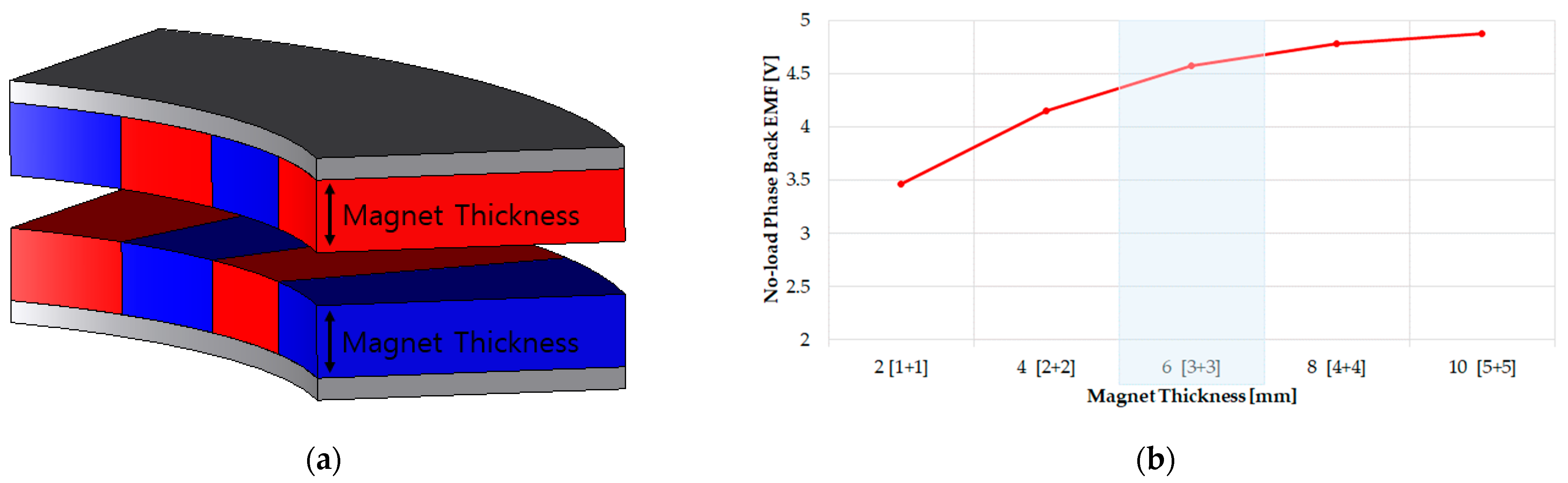
3.4. ASFPMSM Optimal Magnet Size Analysis
3.5. ASFPMSM Optimal Pole Slot Combination Analysis
4. Optimal Designed Model Comparison Analysis
5. Conclusions
Author Contributions
Funding
Institutional Review Board Statement
Informed Consent Statement
Data Availability Statement
Conflicts of Interest
References
- Wu, S.-H.; Hong, X.-S. Integrating Computer Vision and Natural Language Instruction for Collaborative Robot Human-Robot Interaction. In Proceedings of the 2020 International Automatic Control Conference (CACS), Hsinchu, Taiwan, 4–7 November 2020; pp. 1–5. [Google Scholar] [CrossRef]
- Gieras, J.F.; Wang, R.-J.; Kamper, M.J. Axial Flux Permanent Magnet Brushless Machines; Springer Science Business Media B. V.: Berlin, Germany, 2008. [Google Scholar] [CrossRef]
- Hanselman, D. Brushless Motors: Magnetic Design Performance and Control; E-Man Press LLC: Amsterdam, NY, USA, 2012. [Google Scholar]
- Messina, G.; De Bella, E.T.; Morici, L. HTS Axial Flux Permanent Magnets Electrical Machine Prototype: Design and Test Results. IEEE Trans. Appl. Supercond. 2019, 29, 1–5. [Google Scholar] [CrossRef]
- Andriollo, M.; Bettanini, G.; Tortella, A. Design procedure of a small-size axial flux motor with Halbach-type permanent magnet rotor and SMC cores. In Proceedings of the 2013 International Electric Machines & Drives Conference, Chicago, IL, USA, 12–15 May 2013; pp. 775–780. [Google Scholar] [CrossRef]
- Profumo, F.; Zhang, Z.; Tenconi, A. Axial flux machines drives: A new viable solution for electric cars. IEEE Trans. Ind. Electron. 2002, 44, 39–45. [Google Scholar] [CrossRef]
- Polat, M.; Yildiz, A.; Akinci, R. Performance Analysis and Reduction of Torque Ripple of Axial Flux Permanent Magnet Synchronous Motor Manufactured for Electric Vehicles. IEEE Trans. Magn. 2021, 57, 1–9. [Google Scholar] [CrossRef]
- Ueda, Y.; Takahashi, H. Cogging Torque Reduction on Transverse-Flux Motor with Multilevel Skew Configuration of Toothed Cores. IEEE Trans. Magn. 2019, 55, 1–5. [Google Scholar] [CrossRef]
- Jia, L.; Lin, M.; Le, W.; Li, N.; Kong, Y. Dual-Skew Magnet for Cogging Torque Minimization of Axial Flux PMSM With Segmented Stator. IEEE Trans. Magn. 2020, 56, 1–6. [Google Scholar] [CrossRef]
- Polat, M.; Akinci, R. Design and analysis of axial flux double rotor permanent magnet synchronous motor for electric vehicles. Fırat Univ. J. Eng. Sci. 2020, 32, 345–358. [Google Scholar]
- Aydin, M.; Gulec, M.; Demir, Y. Design and validation of a 24-pole coreless axial flux permanent magnet motor for a solar powered vehicle. In Proceedings of the XXII International Conference on Electrical Machines (ICEM), Lausanne, Switzerland, 4–7 September 2016. [Google Scholar]
- Aydin, M.; Gulec, M. Reduction of Cogging Torque in Double-Rotor Axial-Flux Permanent-Magnet Disk Motors: A Review of Cost-Effective Magnet-Skewing Techniques with Experimental Verification. IEEE Trans. Ind. Electron. 2013, 61, 5025–5034. [Google Scholar] [CrossRef]
- Neethu, S.; Nikam, S.P.; Singh, S. High-speed coreless axial-flux permanent-magnet motor with printed circuit board winding. IEEE Trans. 2019, 55, 1954–1962. [Google Scholar]
- Wang, X.; Li, C.; Lou, F. Geometry Optimize of Printed Circuit Board Stator Winding in Coreless Axial Field Permanent Magnet Motor. In Proceedings of the IEEE Vehicle Power and Propulsion Conference (VPPC), Hangzhou, China, 17–20 October 2016; pp. 1–6. [Google Scholar] [CrossRef]
- Jang-Young, C.; Sung-Ho, L.; Kyoung-Jin, K.; Seok-Myeong, J. Improved analytical model for electromagnetic analysis of axial flux machines with double-sided permanent magnet rotor and coreless stator windings. IEEE Trans. Magnet. 2011, 47, 2760–2763. [Google Scholar]
- Gonzalez-Parada, A.; Trillaud, F.; Guzman-Cabrera, R.; Abatal, M. Torque Ripple Reduction in an Axial Flux High Temperature Superconducting Motor. IEEE Trans. Appl. Supercond. 2014, 25, 1–5. [Google Scholar] [CrossRef]
- Bruzinga, G.R.; Filho, A.J.S.; Pelizari, A. Analysis and Design of 3 kW Axial Flux Permanent Magnet Synchronous Motor for Electric Car. IEEE Lat. Am. Trans. 2022, 20, 855–863. [Google Scholar] [CrossRef]
- Zhao, F.; Kim, M.-S.; Kwon, B.-I.; Baek, J.-H. A Small Axial-Flux Vernier Machine with Ring-Type Magnets for the Auto-Focusing Lens Drive System. IEEE Trans. Magn. 2016, 52, 1–4. [Google Scholar] [CrossRef]


| Parameter | Value (mm) |
|---|---|
| Stator Outer Diameter | 82 |
| Stator Inner Diameter | 54 |
| Stator Teeth Width | 3.3 |
| Rotor Outer Diameter | 52.2 |
| Rotor Inner Diameter | 44.8 |
| Magnet Thickness | 5 |
| Air Gap | 1 |
| Stator Stack Length | 10 |
| Rotor Stack Length | 13 |
| Magnet Thickness | 2 |
| Parameter | Value | Unit | |
|---|---|---|---|
| Performance | Pole/Slot | 20/18 | - |
| Rated Speed | 3500 | RPM | |
| Torque @3500 Rotating Per Minutes | 0.55 | Nm | |
| Current | 5.1 | Arms | |
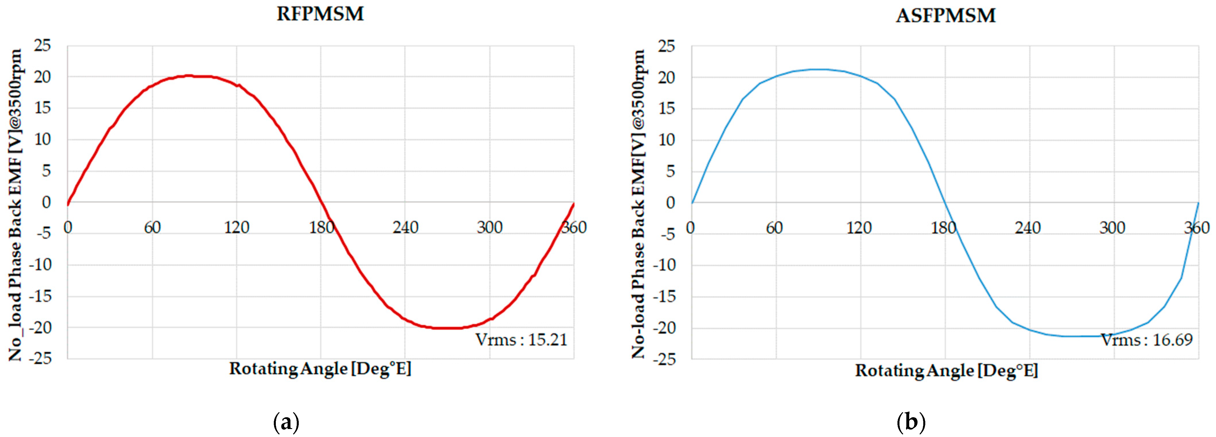
| No-load L-L Back Electric Motive Force @3500 Rotating Per Minutes | 26.28 | Vrms | |
| Copper Loss | 11.1 | W | |
| Iron Core Loss | 12.5 | W | |
| Efficiency | 89.6 | % | |
| Direct Current Link | 48 | V | |
| Winding | Material | Copper | - |
| Diameter | 0.85 | mm | |
| Series Turns Per Phase | 96 | Turns | |
| Magnet | Material | N42SH | - |
| Br | 1.33 | T | |
| Hc | 1592 | kA/m | |
| Poles/Slots | No-Load Phase Back EMF | Number of Serial Turns | Magnet Volume |
|---|---|---|---|
| 24p/36s | 14.87 Vrms | 48 Turn | 19,739 mm3 |
| 28p/42s | 16.62 Vrms | 56 Turn | 19,739 mm3 |
| 32p/48s | 9.11 Vrms | 32 Turn | 19,739 mm3 |
| 36p/54s | 7.74 Vrms | 36 Turn | 19,739 mm3 |
| 48p/72s | 5.93 Vrms | 48 Turn | 19,739 mm3 |
| Parameter | Coil 0.85 | Coil 0.9 | Unit |
|---|---|---|---|
| Current | 5.1 | 5.7 | Arms |
| Coil Diameter | 0.85 | 0.9 | mm |
| Coil Area | 0.57 | 0.64 | mm2 |
| Current Density | 8.98 | 8.98 | A/mm2 |
| Parameter | Value (mm) |
|---|---|
| Rotor Outer Diameter | 52.2 |
| Rotor Inner Diameter | 44.8 |
| Magnet Length | 7.4 |
| Air Gap | 0.3 |
| Motor Stack Length | 13 |
| Magnet Thickness | 3.3 |
| Parameter | Value | Unit | |
|---|---|---|---|
| Performance | Poles/Slots | 28/42 | - |
| Rated Speed | 3500 | RPM | |
| DC Link | 48 | V | |
| Winding | Material | Copper | - |
| Diameter | 0.9 | mm | |
| Series Turns Per Phase | 56 | Turns | |
| Phase Resistance | 0.032 | Ω | |
| Magnet | Material | N42SH | - |
| Br | 1.33 | T | |
| Hc | 1592 | KA/m | |
| Parameter | RFPMSM | ASFPMSM | Unit |
|---|---|---|---|
| RPM | 3500 | r/min | |
| DC Link | 48 | V | |
| Current Density | 8.98 | 8.98 | A/mm2 |
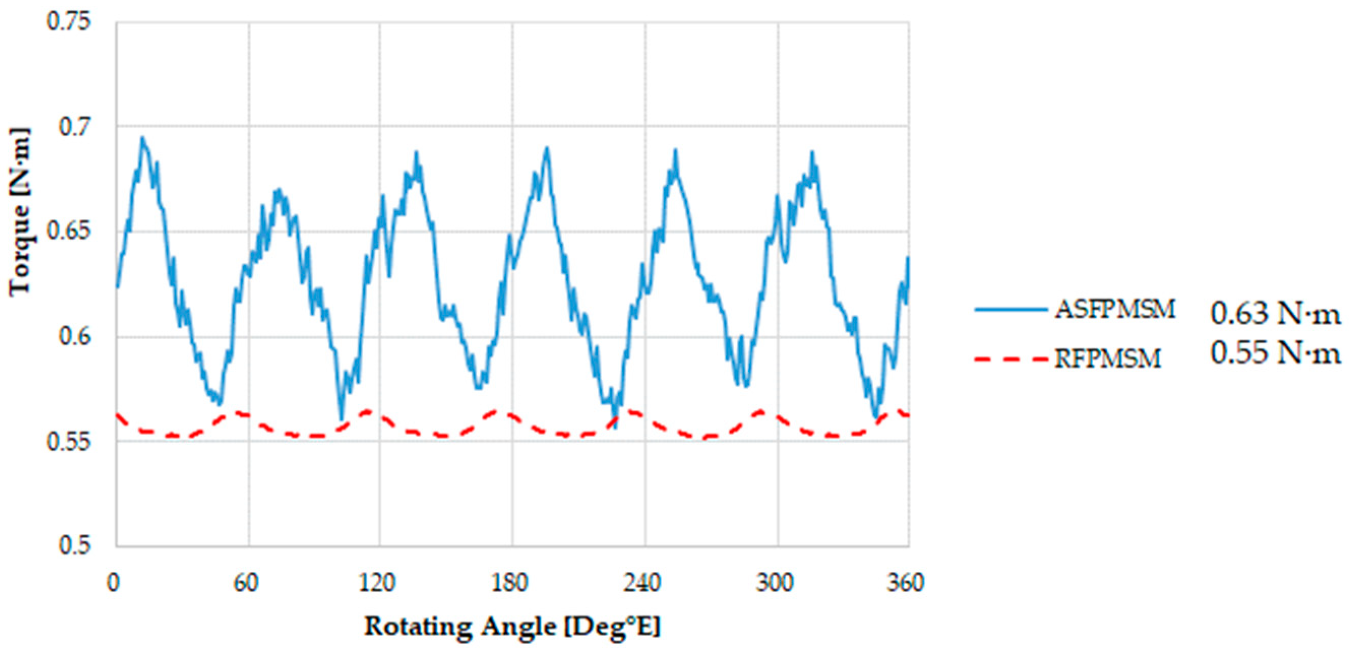
| Torque | 0.55 | 0.63 | N∙m |
| Input | 226.2 | 235.4 | W |
| Copper Loss | 11.1 | 4.48 | W |
| Iron Core Loss | 12.5 | 0.5 | W |
| Output | 202.0 | 230.4 | W |
| Efficiency | 89.6 | 97.9 | % |
Publisher’s Note: MDPI stays neutral with regard to jurisdictional claims in published maps and institutional affiliations. |
© 2022 by the authors. Licensee MDPI, Basel, Switzerland. This article is an open access article distributed under the terms and conditions of the Creative Commons Attribution (CC BY) license (https://creativecommons.org/licenses/by/4.0/).
Share and Cite
Shin, D.-Y.; Jung, M.-J.; Lee, K.-B.; Lee, K.-D.; Kim, W.-H. A Study on the Improvement of Torque Density of an Axial Slot-Less Flux Permanent Magnet Synchronous Motor for Collaborative Robot. Energies 2022, 15, 3464. https://doi.org/10.3390/en15093464
Shin D-Y, Jung M-J, Lee K-B, Lee K-D, Kim W-H. A Study on the Improvement of Torque Density of an Axial Slot-Less Flux Permanent Magnet Synchronous Motor for Collaborative Robot. Energies. 2022; 15(9):3464. https://doi.org/10.3390/en15093464
Chicago/Turabian StyleShin, Dong-Youn, Min-Jae Jung, Kang-Been Lee, Ki-Doek Lee, and Won-Ho Kim. 2022. "A Study on the Improvement of Torque Density of an Axial Slot-Less Flux Permanent Magnet Synchronous Motor for Collaborative Robot" Energies 15, no. 9: 3464. https://doi.org/10.3390/en15093464
APA StyleShin, D.-Y., Jung, M.-J., Lee, K.-B., Lee, K.-D., & Kim, W.-H. (2022). A Study on the Improvement of Torque Density of an Axial Slot-Less Flux Permanent Magnet Synchronous Motor for Collaborative Robot. Energies, 15(9), 3464. https://doi.org/10.3390/en15093464