Article

Single Line/Phase Open Fault-Tolerant Decoupling Control of a Five-Phase Permanent Magnet Synchronous Motor under Different Stator Connections

Department of Electrical Engineering, College of Automation Engineering, Nanjing University of Aeronautics and Astronautics, Nanjing 210016, China
*
Author to whom correspondence should be addressed.
Energies 2022, 15(9), 3366; https://doi.org/10.3390/en15093366
Submission received: 6 April 2022 / Revised: 30 April 2022 / Accepted: 3 May 2022 / Published: 5 May 2022
(This article belongs to the Special Issue Advanced Permanent Magnet Machines and Drives)

Abstract

:
Fault-tolerant control (FTC) of a star-connected Five-phase Permanent Magnet Synchronous Motor (5Φ-PMSM) under open-circuit faults has been extensively studied, among which the decoupled control is attractive and finds a broad application in many fields. Pentacle- and pentagon-connected (generally known as “Penta-connected”) 5Φ-PMSMs are popular due to their low voltage and high-power density, and especially, the demanded DC voltage level for the pentacle-connection mode accounting for merely 1/1.9021 of the star-connection mode, which is very appealing today. On the other hand, as one of the recent advances, the fault-tolerant decoupling control for penta-connections is still yet to be reviewed, and so this study investigates this issue and attempts to find the similarities and dissimilarities between star- and penta-connections under either single-line or single-phase open faults. Torque behavior analysis under, respectively, the fault-tolerant MPPT and id = 0 is conducted to confirm the validity of the presented FTC, and it is expected to provide a reference for selecting a 5Φ-PMSM for practical use.

1. Introduction

Reliability is a constant topic in electrified transportation [1]. To improve the reliability of electric drives, a dual-motor system, where the two motors are coupled on the same shaft, was once popular in some safe-crucial applications [2]. Due to it being costly and bulky, this dual-motor system has been gradually substituted with the latest advances. The rapid progress in semiconductor techniques has stimulated the development of multi-phase windings within one motor to gain enhanced reliability [3]. As such, the multi-phase motor drive has been at the heart of engineering practice and successfully finds its use in more electric aircrafts, electric vehicles, wind energy conversion systems, and ship propulsion [4]. A five-phase permanent magnet synchronous motor (5Φ-PMSM) can be an outstanding candidate for using decent numbers of power switches [5], in addition to its high torque density and small torque ripples [6]. It is well known that a 3Φ-PMSM can be wired into star-connection, delta-connection, and star–delta connection modes, as well as open-end winding, regardless of whether the windings are series- or parallel-connected [7,8]. However, regarding a 5Φ-PMSM, except for star-connection and open-end winding modes, it can also be wired into the star-, pentagon-, and pentacle-connection (known as penta-connection) modes, as well as the combination of two of them [9]. Overall, the demanded DC link voltage for a pentacle-connected PMSM is merely 1/1.9021 of its star-connected counterpart [10]. Given this, the penta-connection mode is very attractive and may find a broad future in many high-power and low-voltage applications.
An open circuit fault is one of the most common types of fault in an electric drive [9]. To cope with this fault, the remaining winding phases of a 5Φ-PMSM have to be re-energized properly in the post-fault operation [10]. Regarding an open-winding five-phase machine, Pengye Wang, in [11], introduces a new inverter topology reconfiguration method along with a fault-tolerant control (FTC) strategy, which utilizes the bidirectional switching devices to respond to the open-circuit event on different phases. Zuosheng Yin [12] proposes a short-circuited FTC also for an open winding machine, and it features an equal current amplitude and sinusoidal waveform current, as well as maximum average torque. Concerning the torque ripple reduction, Qian Chen in [13] proposes a third harmonic injection method to reduce the torque ripple caused by the shorted phase for the star-connection mode. Li Zhang in [14] comes up with a generalized FTC scheme for both field-oriented control (FOC) and direct torque control (DTC) under open-line faults, avoiding the use of different transforming matrices under different fault conditions. Recently, model predictive fault-tolerant control has attracted much attention, however, most of them are dedicated to a star-connected motor. For instance, reference [15] proposes a multi-vector-based model predictive control with voltage error-tracking short-circuit faults, including a single-phase short-circuit fault and inter-phase short-circuit fault. Reference [16] proposes a virtual voltage vector-based model predictive control for an open line fault, which claims to reduce the computational burden.
On the other hand, reference [17] provides a comprehensive comparison of the post-fault torque capability for 5Φ-PMSMs under all connection conditions with open-circuit phase and line faults. The mirror symmetry theory in combination with the balance of power theory is used, however, the reluctance torque is not considered. Reference [18] states that some stator winding configurations other than star-connection yield a small copper loss and increased torque capacity under the same torque command for a dual three-phase drive. Among star-, pentagon-, and combined Star/Pentagon-connection modes, reference [19] suggests that the star-connection mode produces the lowest average torque and highest ripple torque, whereas the pentagon connection mode gives the highest average torque and minimum ripple torque, and the star/pentagon-connection mode mediates between both. Reference [20] concludes the maximum available torque that a five-phase induction motor (5Φ-IM) can deliver under open-circuit phase faults, where all connection conditions are tested using a unified balanced power source. Reference [21] also investigates the torque ripple-free operation of all connection modes under an open-circuit phase and line fault, and it confirms that a penta-connection mode outputs a higher torque than a star-connection mode. Reference [22] put forward an open line FTC to maximize the average torque and minimize the ripple torque for a combined star/pentagon-connected SynRM fed from a matrix converter. Reference [10] concludes that the performance of a pentagon-connection mode with a single-line open fault under open-loop control is advantageous over the star-connection mode. For optimal current control, although the star-connection mode results in a better current waveform, the copper loss can be less using a pentagon-connection mode. Regarding a pentacle-connected induction motor under one phase supply failure, Reference [23] proves that a 5Φ-PMSM can switch to a three-phase operation state without an electromagnetic torque ripple. Reference [24] investigates the phase transposition on the five-phase induction machine with different stator connection modes, namely, star, pentagon, and pentacle. Owing to the lower derating factor of the pentacle-connection mode under the open phase, Reference [25] proposes a fault-tolerant motor using a combined star/pentacle-connection.
Given the previous achievements, specifically, those under penta-connection modes, the optimal current references are usually solved under the natural coordinate frame, and the hysteresis current controller or resonant current controller is therefore adopted. However, the line/phase voltage modulation does not take care of the zero-sequence component, and this constitutes a huge disturbance to the closed-loop current regulation. On the other hand, the decoupled control, which relies on decoupled modeling, plays an important role in today’s variable-speed drive and has become a standard technique in the industry sector [13,26,27]. To enable the continuous use of a decoupled FTC under penta-connection modes, this work firstly explores the similarity and dissimilarity between star-connection and penta-connection, and then raises a unified FTC under, respectively, the single open-line fault and the single open-phase fault, and also elaborated are the key technique details to unlock this decoupled FTC. To be specific, for a single open-line fault, the transformation of resistance, inductance, and back-EMF from the penta-connection to the star-connection is conducted, along with the angular of vectorial control properly fixed. Regarding the single open-phase fault, voltage and current transformation from a line-to-line frame to a winding-oriented frame is proposed by incorporating the zero-sequence voltage and current. Finally, experimental results on id = 0 and Maximum Torque Per Ampere (MTPA) are carried out, which confirms the validity of the presented decoupled FTC for all connection modes.

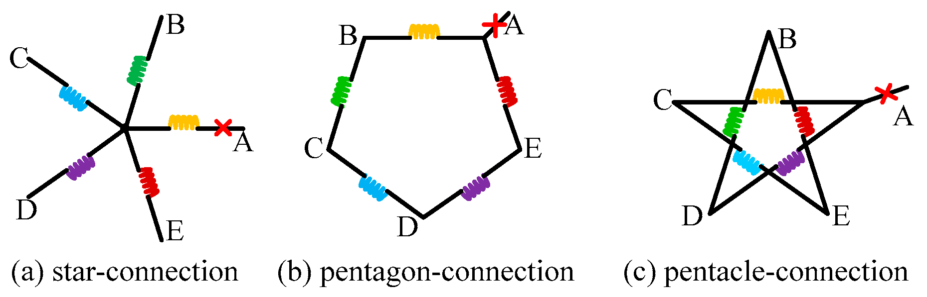
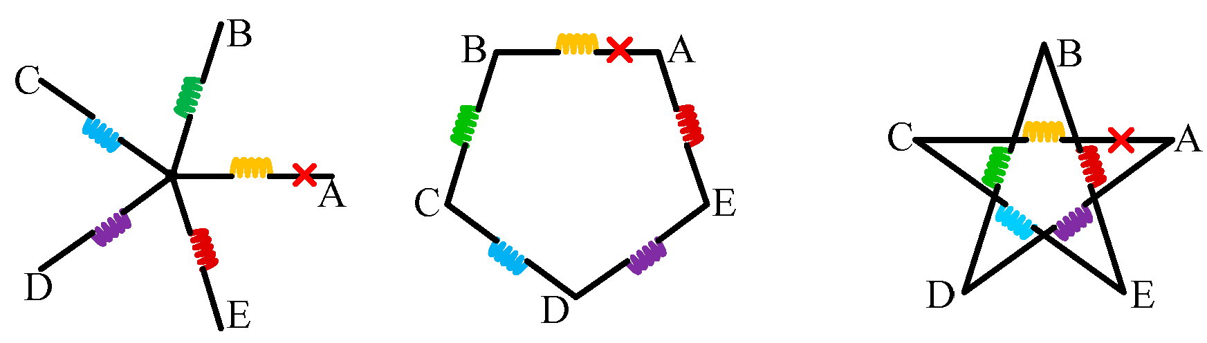
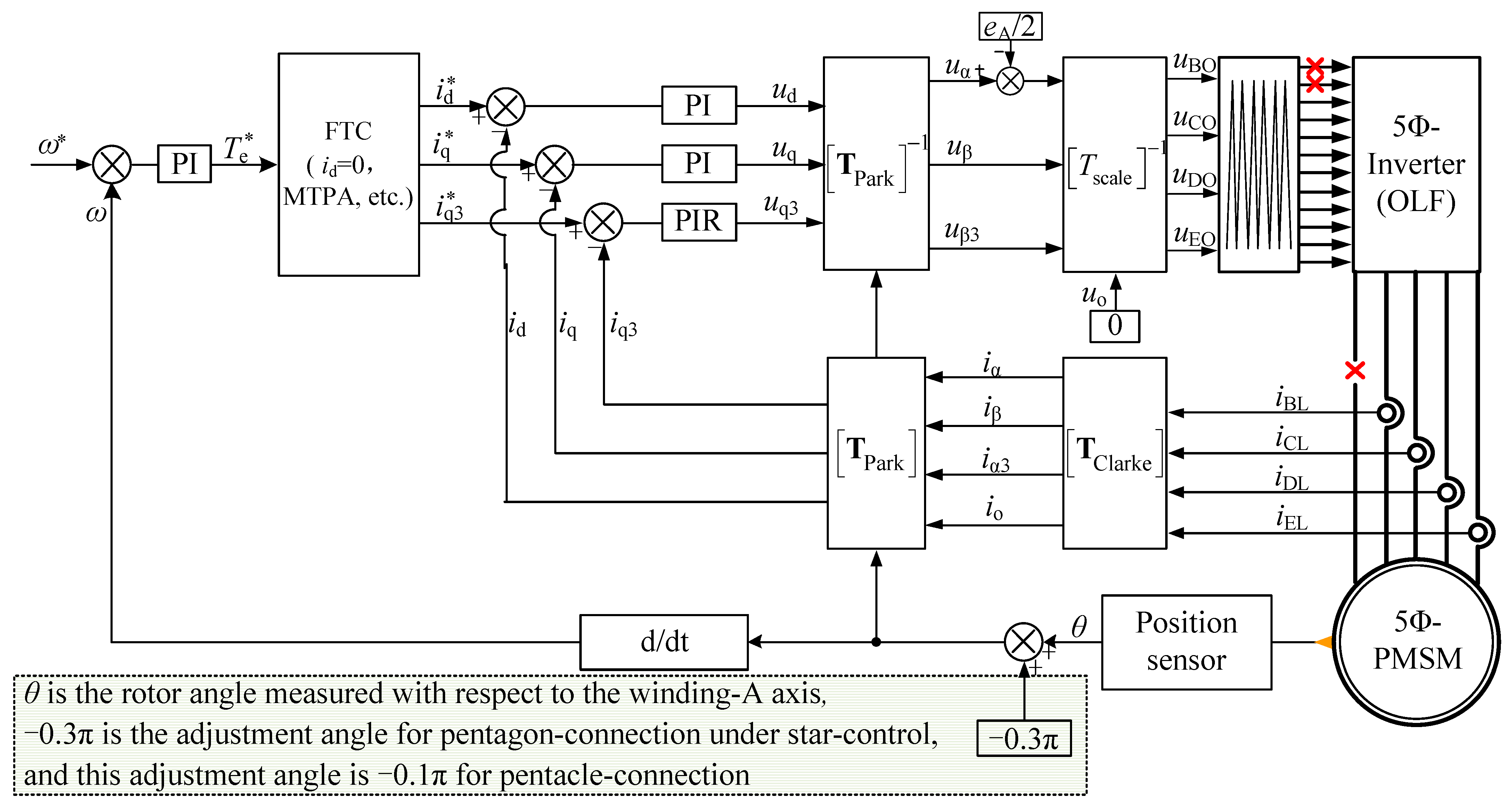
2. Single Line Open FTC

The 5Φ-PMSM’s stator windings can be wired into either star-, pentagon-, or pentacle-connection modes, as revealed by Figure 1, and among them, the pentagon-connection features a series connection of two adjacent sets of windings, while the pentacle-connection features a series connection of two non-adjacent sets of windings. Since the pentagon can be viewed as a convex polygon and the pentacle is a kind of concave polygon, the latter two connection modes in Figure 1 can be unified, which is termed a penta-connection in this paper. Since one cannot differentiate a motor’s connection mode from the outside, from the inverter’s perspective, a generalized control scheme for all connection modes is therefore possible.
On the other hand, the withstanding voltage of one winding phase is different from the star- to penta-connection modes, even when powered by the same DC power source. Overall, the winding phase voltage for a pentagon-connection mode is 1/1.1172 of that under a star-connection mode, and this ratio reduces to 1/1.902 for a pentacle-connection mode. Therefore, a penta-connection mode is more suitable for low-voltage and high-power applications, such as electrified transportation, and this property resembles a conventional delta-connected three-phase motor.

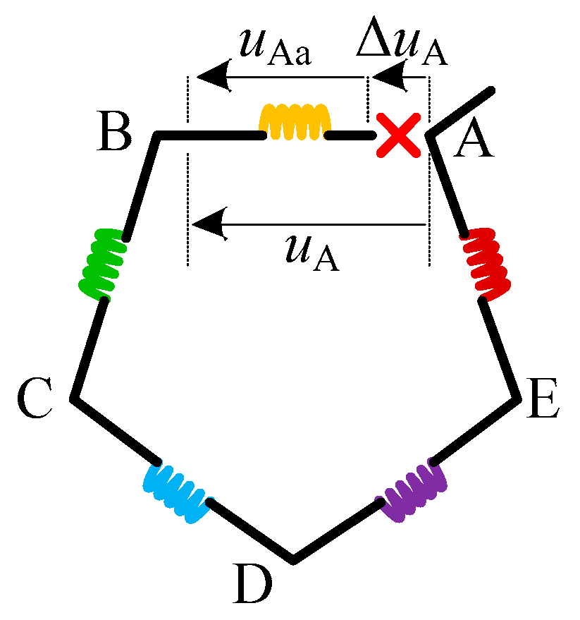
2.1. Star-Connection

The open-circuit fault accounts for one of the most common faults in an electric drive. The open-circuit fault comprises an open-line fault and an open-phase fault, and to avoid confusion, they are illustrated in Figure 2 and Figure 3, respectively.
For a star-connection mode, the open-line fault and open-phase fault create the same effect since the phase and line are the same. Thus, their fault-tolerant decoupling controls are the same, and hereby termed “star-control”. Readers may refer to Figure 4 for an overview of the star-control under a single-line open fault, where the adopted Clarke transformation is no longer a unitary matrix to offer unbalanced voltages even with a balanced ud and uq. Notice that superscript * indicates the reference value.
In this way, the post-fault torque performance can be maintained as stable enough by merely using open-loop voltage control. The involved matrices for this decoupled FTC are referred to in (1)–(3) [28]. In addition, in the figure, eA/2 is introduced to compensate for the oscillating neutral voltage post fault, which must be used in combination with Tscalar to ensure the line voltage modulation work as anticipated [29]. It has to be emphasized that eA corresponds to the line-to-neutral back-EMF, and it is easy to acquire/estimate with merely rotor flux linkage parameters. The acquisition of eA under penta-connection modes is detailed in the section below.
T scalar = 2 5 [ cos δ + 1 4 cos 2 δ + 1 4 cos 3 δ + 1 4 cos 4 δ + 1 4 sin δ sin 2 δ sin 3 δ sin 4 δ sin 3 δ sin 6 δ sin 9 δ sin 12 δ 1 1 1 1 ]
T Clarke = 2 5 [ cos δ 1 cos 2 δ 1 cos 3 δ 1 cos 4 δ 1 sin δ sin 2 δ sin 3 δ sin 4 δ sin 3 δ sin 6 δ sin 9 δ sin 12 δ 1 1 1 1 ]
T Park = [ cos θ sin θ 0 0 sin θ cos θ 0 0 0 0 1 0 0 0 0 1 ]

2.2. Pentagon-Connection

The mathematical model of each connection mode can be equivalent to each other as long as the motor is not damaged from the inside. From the inverter’s perspective, the fault-tolerant current for all connection modes has the potential to be unified. This means the star-control can be also available to the penta-connection mode under the open line fault. It must be mentioned that the use of star-control is conditional, and several important control parameters have to be transformed from the penta-connection mode into the star-connection mode. A total of four paramount parameters need rectification.
Take the pentagon-connection mode as an example. According to Figure 1a,b, the line-to-neutral resistance of a pentacle-connected motor is calculated by
2 R = 4 R ϕ R ϕ 4 R ϕ + R ϕ
where R herein indicates the line-to-neutral resistance of an equivalent star-connection, and Rϕ is the winding phase resistance.
The simplification of the above equation yields
R = 0.4 R ϕ
Similarly, the relationship of inductance between the line-to-neutral frame and a winding-oriented frame is shown below
L = 0.4 L ϕ
where L herein indicates the self- or mutual-inductance (instantaneous value) measured between one of the motor’s five terminals and the neutral point, and L ϕ is the winding phase inductance (also an instantaneous value).
The line-to-neutral back-EMF is manifested as the line-to-neutral voltage under no-load conditions, and thanks to the matrix that transforms the line voltages to line-to-neutral voltages of the health condition, one can obtain the detailed representation of the back-EMFs in the sense of a star-connection, as below
{ e A = ω λ r 1 ϕ sin ( θ 0.3 π ) 1.1172 + 3 ω λ r 3 ϕ sin ( 3 ( θ 0.3 π ) ) 1.9021 e B = ω λ r 1 ϕ sin ( θ 0.3 π + δ ) 1.1172 + 3 ω λ r 3 ϕ sin ( 3 ( θ 0.3 π + δ ) ) 1.9021 e C = ω λ r 1 ϕ sin ( θ 0.3 π + 2 δ ) 1.1172 + 3 ω λ r 3 ϕ sin ( 3 ( θ 0.3 π + 2 δ ) ) 1.9021 e D = ω λ r 1 ϕ sin ( θ 0.3 π + 3 δ ) 1.1172 + 3 ω λ r 3 ϕ sin ( 3 ( θ 0.3 π + 3 δ ) ) 1.9021 e E = ω λ r 1 ϕ sin ( θ 0.3 π + 4 δ ) 1.1172 + 3 ω λ r 3 ϕ sin ( 3 ( θ 0.3 π + 4 δ ) ) 1.9021
where λr1−ϕ and λr3−ϕ are the magnitudes of, respectively, the 1st and 3rd rotor flux linkages that are measured under the winding-oriented frame. From (7), the ratio of the 3rd to 1st harmonic back-EMFs shrinks to 0.587, i.e., 1.1172/1.9021, of that under the real star-connection mode, which means the 3rd rotor flux is dampened with a pentagon-connection, while comparing the star-connection mode with the base value per unit.
Finally, to correctly use FTC, the position angle for FOC also needs modification, which can be adjusted by biasing the existing position with a constant value of −0.3π (this angular can be inferred from the line-to-neutral back-EMF’s representation). The above manipulation enables us to continually use a star-control even under the pentagon-connection.
The post-fault torque can be given by the following equation on the premise that all parameters have been transformed into the star-connection.
T e = 5 p 2 [ i d i q ( L d L q ) + i q λ r 1 ] + 5 p λ r 3 2 [ 3 i q 3 + 3 ( i d sin 2 θ + i d sin 4 θ i q cos 2 θ + i q cos 4 θ ) 2 ]
Here, Ld, Lq, Lq3 are the inductances under a fault-tolerant synchronously rotating frame, and they shrink to 0.4 of those under a star-connection mode as per (6). λr1 and λr3 are the magnitudes of, respectively, the 1st and 3rd rotor flux linkages under the line-to-neutral frame which shrinks to, respectively, 1/1.1172, and 1/1.9021 of those under a star-connection mode, as per (7).
Notice also that the impact of the magnetic saturation and cross saturation on the d-q-q3 frame inductances are not considered in FTC currently, and this may affect the torque ripple to some extent while evaluating the decoupled FTC experimentally. However, this effect is within a controllable range as FTC is usually not targeting a precise torque control.

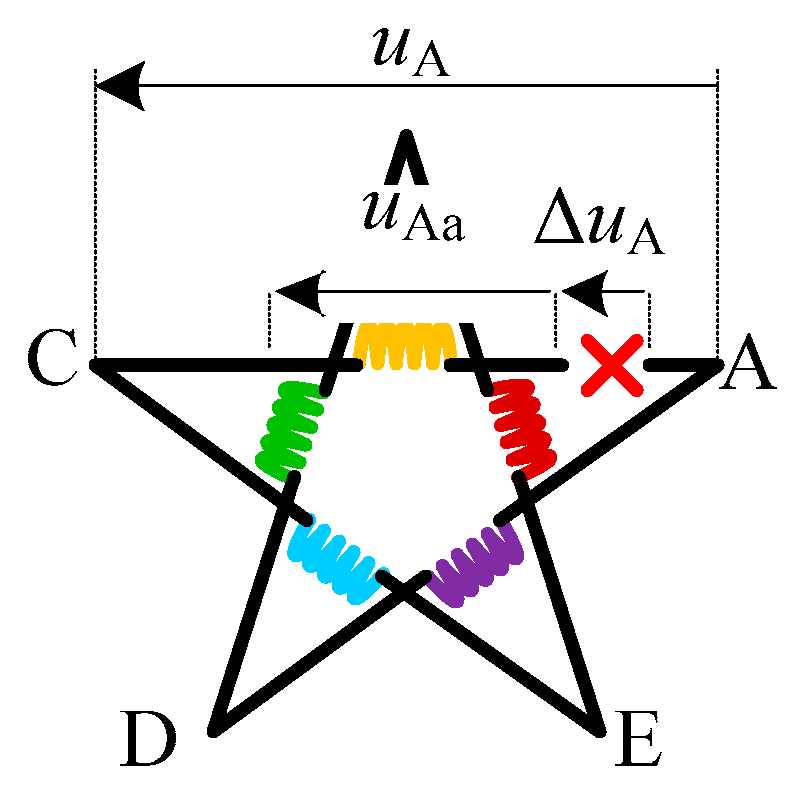
2.3. Pentacle-Connection

As a summary, parameters from the pentacle-connection sense to the star-connection sense are also derived as below
R = 0.6 R ϕ
L = 0.6 L ϕ
Likewise, under the pentagon-connection mode, the line-to-neutral back-EMF is derived as below
{ e A = ω λ r 1 ϕ sin ( θ 0.1 π ) 1.9021 3 ω λ r 3 ϕ sin ( 3 ( θ 0.1 π ) ) 1.1172 e B = ω λ r 1 ϕ sin ( θ 0.1 π + δ ) 1.9021 3 ω λ r 3 ϕ sin ( 3 ( θ 0.1 π + δ ) ) 1.1172 e C = ω λ r 1 ϕ sin ( θ 0.1 π + 2 δ ) 1.9021 3 ω λ r 3 ϕ sin ( 3 ( θ 0.1 π + 2 δ ) ) 1.1172 e D = ω λ r 1 ϕ sin ( θ 0.1 π + 3 δ ) 1.9021 3 ω λ r 3 ϕ sin ( 3 ( θ 0.1 π + 3 δ ) ) 1.1172 e E = ω λ r 1 ϕ sin ( θ 0.1 π + 4 δ ) 1.9021 3 ω λ r 3 ϕ sin ( 3 ( θ 0.1 π + 4 δ ) ) 1.1172
From (11), the ratio of the 3rd to 1st harmonic back-EMFs increases to 1.703, i.e., 1.9021/1.1172, compared with the base value 1 set by the star-connection mode.
Moreover, the adjustment angle for using a star-control is supposed −0.1π under the pentacle-connection mode (this bias angle can also be inferred from the line-to-neutral back-EMF). Furthermore, the Ld, Lq, Lq3, and λr1, as well as λr3 also need calibration for the torque control, and the scaling factor can be deduced from (10) and (11).
An experiment will be carried out to demonstrate the validity of the FTC using the same star-control for all connection modes.

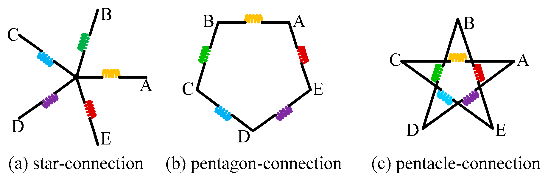
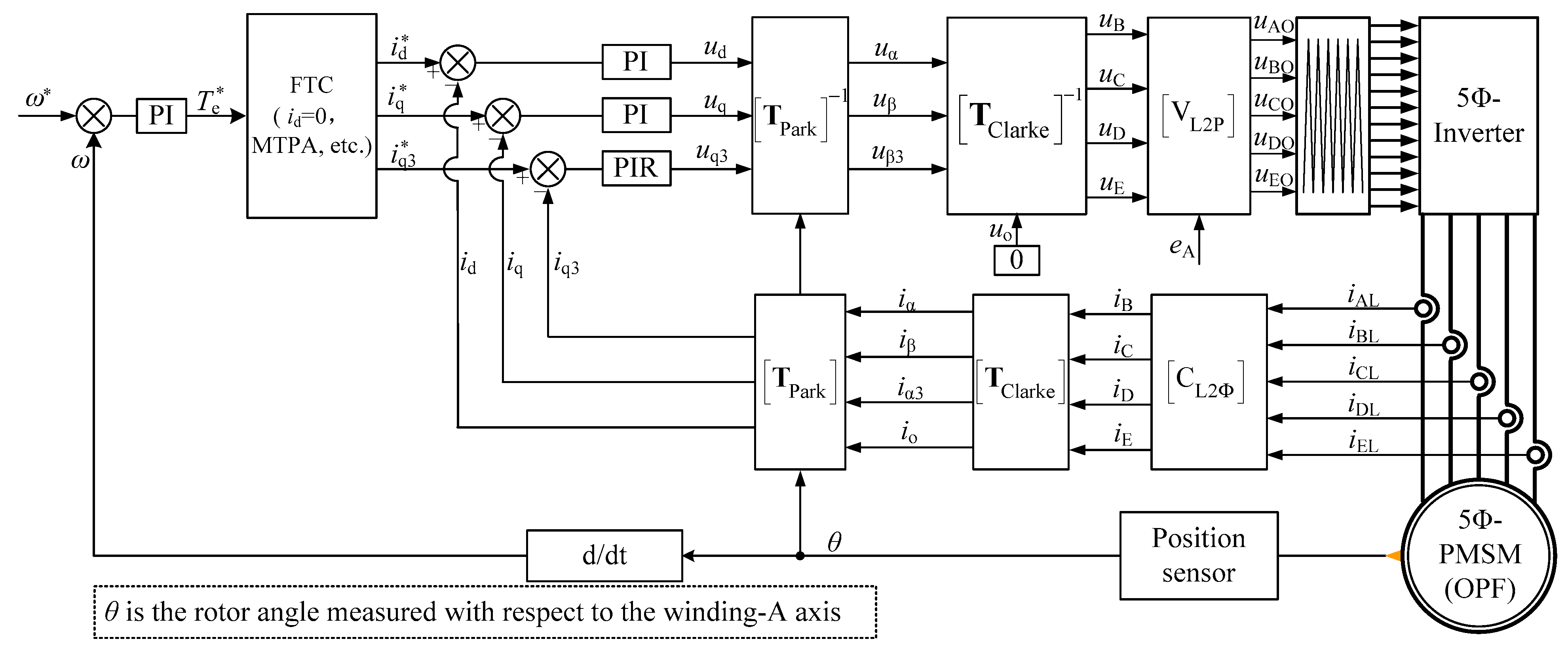
3. Single Phase Open FTC

3.1. Pentagon-Connection

The FTC of a star-connection mode under an open-phase fault maintains the same as the previous open-line fault. However, regarding the penta-connection mode, an open-phase fault and open-line fault make a big difference; this is because the equivalent conversion between motor models does not hold under this condition. To achieve a unified open-phase FTC for all connection modes, the FTC should be built onto a winding-oriented frame.
To this end, the difference between a star-connected motor and a penta-connected motor should be firstly figured out. For all connection modes, should we observe the motor from the winding-oriented frame, the models under all connections, even with an open-phase fault, are no different from each other, and this lays a theoretical foundation for achieving a unified FTC. To this end, one has to change the control feedbacks, i.e., the sampled currents, from a line-to-line frame to a winding-oriented frame, as well as the control outputs, i.e., voltage, from the line-to-line frame to a pole-voltage frame. In this way, the fault-tolerant decoupling control, which is originally derived from a star-connected motor, still has a chance to be applied under the penta-connection mode.
Without a loss of generality, assume the stator is pentagon-connected, and let iAL, iBL, iCL, iDL, and iEL denote the line-to-line currents, and iA, iB, iC, iD, and iE the winding phase currents.
By applying Kirchhoff’s Current Law to Figure 3b, one can obtain
[ i AL i BL i CL i DL i EL ] = [ 0 0 0 0 1 0 1 0 0 0 0 1 1 0 0 0 0 1 1 0 0 0 0 1 1 ] [ i A i B i C i D i E ] ,   i A = 0
The above formula involves a singular matrix, and this means that the solutions for iB, iC, iD, and iE can be multiple under an already known iAL, iBL, iCL, iDL, and iEL. To obtain a unique solution, some extra constraints have to be imposed.
A zero-sequence circulating current (ZSCC) can be the next dimension to decide the winding phase currents. A ZSCC is common in a delta-wired, as well as penta-wired drive. Usually, a ZSCC is harmful as it generates heat and makes the torque fluctuate. Therefore, a ZSCC is not desired in most situations.
This faulty drive also expects a null ZSCC, which means
i B + i C + i D + i E = 0 ,   i A = 0
It has to be emphasized that the winding phase currents estimated from the measured line currents contain no ZSCC now. However, in reality, a ZSCC still appears in the actual winding phase currents even with winding-A open-circuited. Rather than circulating among five balanced winding phases under the health condition, the circulating path of a ZSCC includes the inverter’s active legs in fault mode. A ZSCC is difficult to suppress without further knowledge of the winding phase current in a penta-wired system.
Combining (13) with (12), one can estimate the winding phase currents without a ZSCC, and the analytical solutions are shown below.
[ i B i C i D i E ] T = C L 2 Φ [ i AL i BL i CL i DL i EL ] T
where
C L 2 Φ = [ 0 1 3 1 2 3 1 3 0 1 3 0 2 3 1 3 0 1 3 0 1 3 1 3 0 1 3 0 1 3 2 3 ]
In this way, the winding phase currents, which are not easy to measure in a pentagon-wired drive, can be acquired now, and they will be sent to the current controller for monitoring the torque behavior.
Simultaneously, the modulation of the pole voltage (relative to the midpoint of the DC bus) also needs rectification to correctly generate the wanted line-to-line voltages. The relationship between the line-to-line voltage and the pole voltage can be always represented, as below, under either healthy or fault conditions,
[ u A u B u C u D u E ] = [ 1 1 0 0 0 0 1 1 0 0 0 0 1 1 0 0 0 0 1 1 1 0 0 0 1 ] [ u AO u BO u CO u DO u EO ]
where ux, with x = A, B, C, D, and E represents the line-to-line voltage. The above matrix is also singular, and to obtain a unique solution for the demanded pole voltage, one needs to raise some additional constraints.
Likewise, the common-mode voltage (averaged value) can be used as another dimension to decide the pole voltage solutions. The common-mode voltage often takes a switching pattern in an inverter-driven system, however, it is often averaged to zero concerning the fundamental components of the pole voltages, and hereby the ‘pole’ point refers to the midpoint of the DC-bus. It is also expected that this property could still hold, and thus the following constraint is imposed
u AO + u BO + u CO + u DO + u EO = 0
By incorporating (17) into (16), and then applying the inverse operation, one can have
[ u AO u BO u CO u DO u EO ] T = V L 2 P [ u A u B u C u D u E ] T
V L 2 P = [ 2 5 1 5 0 1 5 2 5 2 5 2 5 1 5 0 1 5 1 5 2 5 2 5 1 5 0 0 1 5 2 5 2 5 1 5 1 5 0 1 5 2 5 2 5 ]
where uB, uC, uD, and uE can be obtained by
[ u B u C u D u E ] = [ T Clarke ] 1 [ T Park ] 1 [ u d u q u q 3 0 ]
where ud, uq, and uq3 are the output actions of the current PI controller and denote the line-to-line voltage references under a fault-tolerant synchronously rotating frame. Evidently, with the presented line-to-phase/pole matrices, i.e., CL2Φ and VL2P, the current feedback and pole voltage modulation can be rectified to perfectly match the decoupled model that was originally developed for a star-connected motor.
From (18), uA is pivotal while solving the pole voltage solutions. As aforementioned in the star-connection case, uA can be replaced by the back-EMF of winding-A because of there being no current flowing through the open-circuited phase. Up to this point, it may remain questionable whether the same approximation applies to a penta-wired drive. As another contribution, this paper proves that the above hypothesis can still find its use in this context.
In response to the missing representation of uA, its definition has to be clarified first. As uA represents the line-to-line voltage between motor terminals-A and -B, it is no longer identical to winding-A’s phase voltage when phase-A is open-circuited.
Figure 5 depicts the details of a pentagon-wired drive with phase-A being open-circuited. From the figure, the winding-A’s phase voltage, i.e., uAa, is not equal to the corresponding line-to-line voltage, i.e., uA, any longer, and the difference lies in ΔuA which is supposed to vary along with the ZSCC. As per Figure 5, the relationship between uAa and uA can be represented by
u A = u Aa + Δ u A
The zero-sequence voltage is defined as
u o =   u Aa + u B + u C + u D + u E
where uo is the phase zero-sequence voltage in the context of winding-A open-circuited, and it is calculated by summing all five winding phase voltages.
By substituting (21) into (22), it can be proved that
u o = u Aa + u B + u C + u D + u E   = u A Δ u A + u B + u C + u D + u E = Δ u A
As per the Appendix A, uo, or rather ΔuA, usually comes in a pair with the ZSCC, and the actual ZSCC depends on the zero-sequence impendence in this unbalanced system.
In engineering practice, uo is unmeasurable, and thus it is overlooked in this work. On the other hand, by substituting uA with its back-EMF because of there being no current circulating through the open-circuited winding, one can have
u A u Aa e A
The proposed fault-tolerant decoupling control of a pentagon-connected drive is illustrated in the next section, which is based on a star-connection drive by including two matrices in connection with the feedback and output rectification.

3.2. Pentacle-Connection

Similarly, in the context of pentacle-connection, both line-to-line currents and the line-to-pole voltage need rectification.
Regarding the line-to-line currents, one can have
[ i AL i BL i CL i DL i EL ] = [ 0 0 0 1 0 0 1 0 0 1 0 0 1 0 0 0 1 0 1 0 0 0 1 0 1 ] [ i A i B i C i D i E ] ,   i A = 0
By imposing zero ZSCC constraints, as below
i B + i C + i D + i E = 0 ,   i A = 0
one can obtain the phase currents
[ i B i C i D i E ] T = C L 2 Φ [ i AL i BL i CL i DL i EL ] T
where CL2Φ is represented by
C L 2 Φ = [ 0 1 3 1 3 1 3 0 0 2 3 1 3 1 3 1 0 1 3 1 3 2 3 0 0 2 3 1 3 1 3 0 ]
With regard to the line-to-pole voltage transformation, one can always have
[ u A u B u C u D u E ] = [ 1 0 1 0 0 0 1 0 1 0 0 0 1 0 1 1 0 0 1 0 0 1 0 0 1 ] [ u AO u BO u CO u DO u EO ]
Additionally, imposing a zero common-mode voltage constraint as below
u AO + u BO + u CO + u DO + u EO = 0
can yield
[ u AO u BO u CO u DO u EO ] T = V L 2 P [ u A u B u C u D u E ] T
where VL2P can be calculated by
V L 2 P = [ 2 5 1 5 1 5 2 5 0 0 2 5 1 5 1 5 2 5 2 5 0 2 5 1 5 1 5 1 5 2 5 0 2 5 1 5 1 5 1 5 2 5 0 2 5 ]
Figure 6 shows the graphical relationship between uA and uAa under a pentacle-connection, where uAa is the winding phase voltage and can be approximated as a back-EMF component when the corresponding phase winding is open-circuited. By neglecting ΔuA, which is usually not measured in practice, uA is finally substituted by eA.
Figure 7 refers to a unified open phase fault-tolerant decoupling control for all connections, where one only has to change CL2φ and VL2P to enable the FTC under the preferred connection. Notice that all five IGBT bridges are still available in this context, whereas only four bridges are controllable in an open-phase fault, as revealed in Figure 4. Therefore, the torque derating will be less under single-phase open FTC, and it is not possible to merge the two control schemes into one.

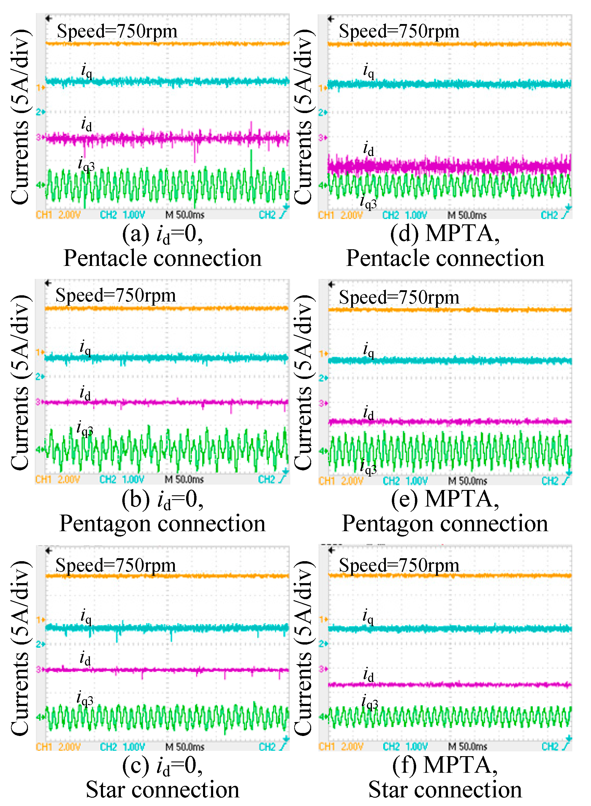
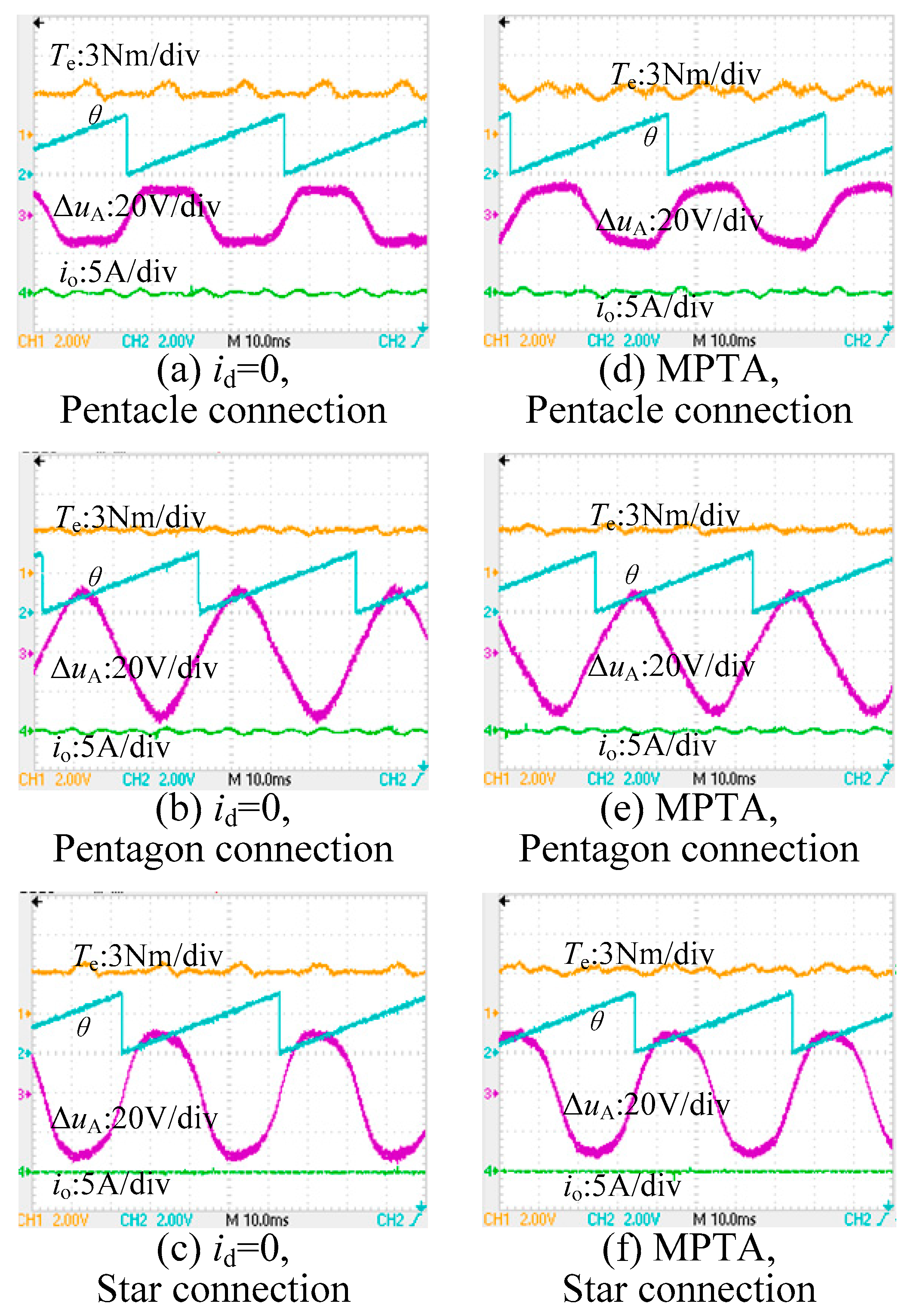
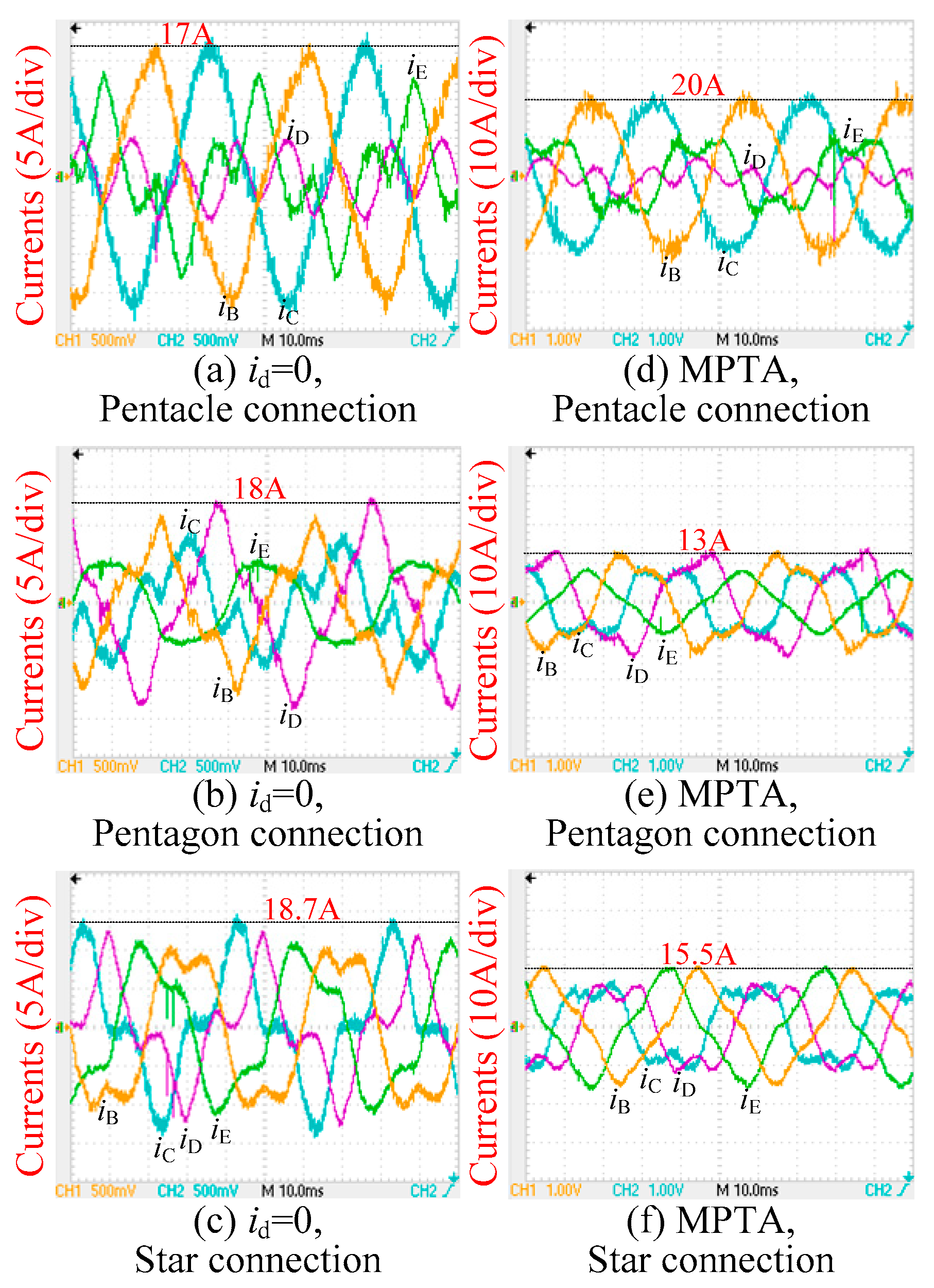
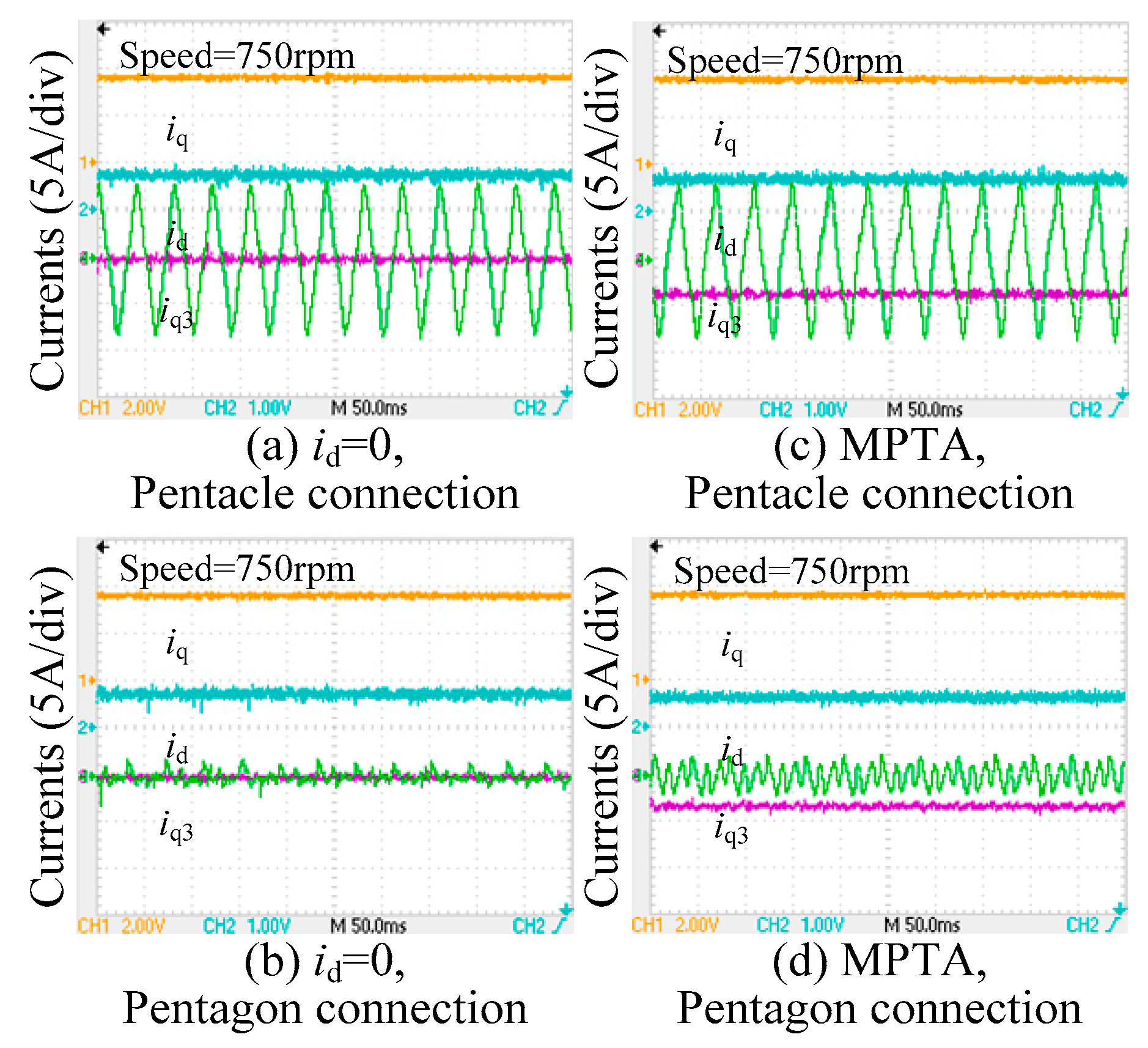
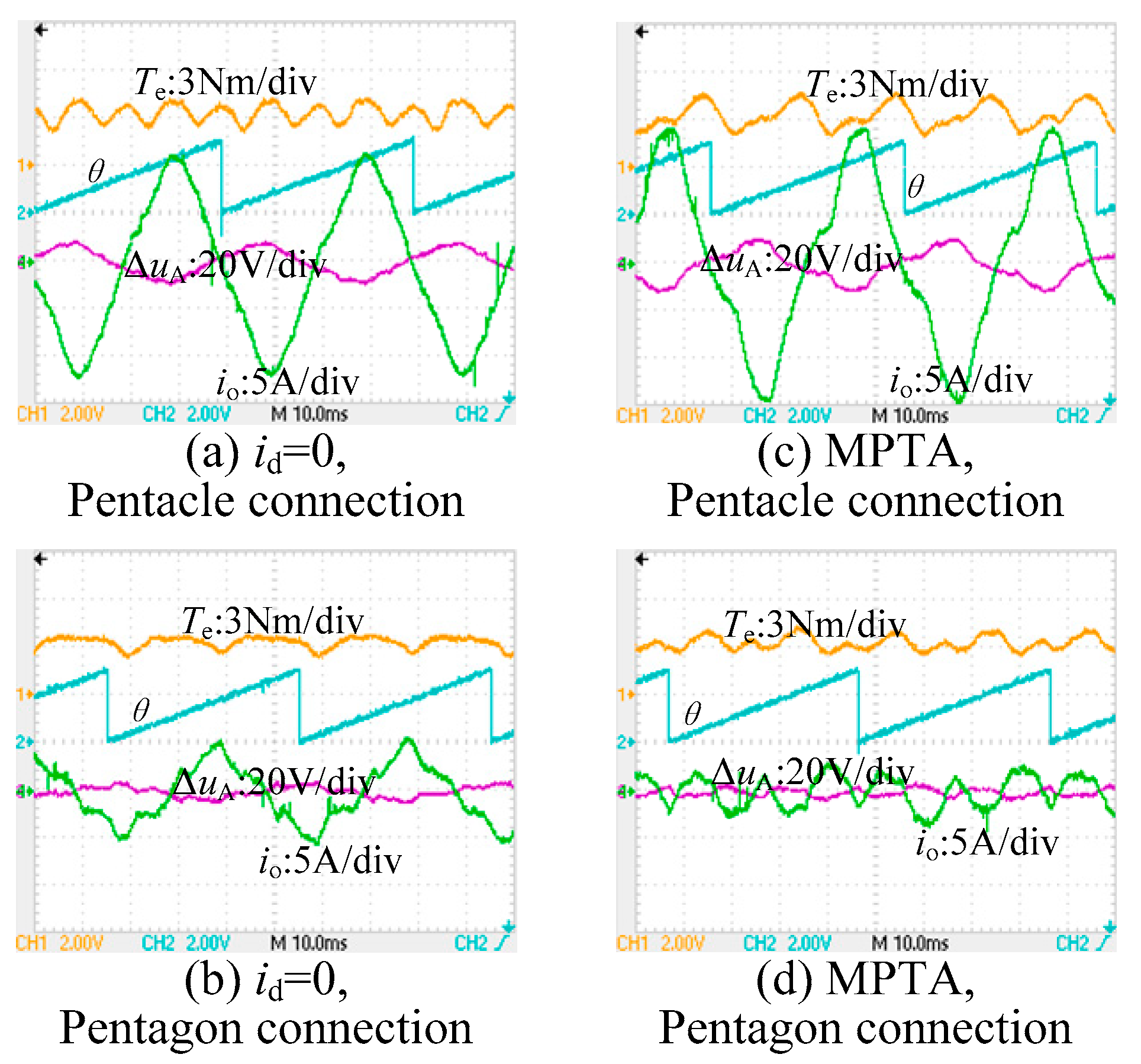
4. Experimental Results

A laboratory-scale 5Φ-PMSM, having its shaft coupled to a three-phase PM synchronous generator, has been developed to validate the presented fault-tolerant decoupling control for all connection modes under a single-line/phase open fault. The investigated 5Φ-PMSM is fed by an IGBT-based five-phase half-bridge inverter, with its parameters referred to Table 1. The 1st and 3rd harmonics of the rotor flux are measured by letting the 5Φ-PMSM work in generation mode, and deduced from its winding phase back-EMFs.
Two control schemes, i.e., id = 0 to minimize the torque ripples and MTPA to maximize the torque capacity, are evaluated in the experiment, where the speed is regulated to a constant 750 rpm with a single PI controller. The output action of the speed PI, i.e., a torque command, is fed to a q-axis current regulator, and iq3 is subject to open-loop voltage control, which helps to reduce the torque ripples. The FTC for all connection modes under an open-line fault is conducted firstly, and then the open-phase FTC comes after. As phase-A and line-A are the same for the star-connection, the torque and current behaviors of the FTC under an open-phase fault are referred to in the case of an open-line fault. In addition, the torque and current performance post-fault under a star-connection also serves as a benchmark for comparing with a penta-connection mode under the same fault conditions.

4.1. Single-Line Open Fault

Figure 8 refers to the behavior of d-q-q3 frame currents with line-A open-circuited. From Figure 8a–c, which are evaluated under the control of id = 0, the optimal value of iq to achieve a constant speed of 750 rpm differentiates under different connection modes, and it decreases from a pentacle-connection to pentagon-connection, and is then followed by a star-connection mode. This is because their respective line-to-neutral back-EMFs increase and this phenomenon can be explained by (7) and (11). On the other hand, the feedbacks, id and iq, are DCs, and evidently, the star-control philosophy works well for all connection modes under a single open-line fault.
Figure 8d–f show the same currents under an MTPA control, and the value of iq decreases to preserve the motor at a constant 750 rpm, compared with their counterparts under the control of id = 0. This is because reluctance torque is utilized in this case which boosts the torque capacity to some extent. Under either id = 0 or MTPA control, the speed profile is smooth, and it proves the capability of the star-control for all connection modes under a single open-line fault.
Figure 9 shows the waveforms of the torque, ΔuA, and ZSCC, where io denotes the sum of all five winding phase currents, and herein is calculated by sampling four line-currents together with one winding phase current. Figure 9a–c corresponds to the control of id = 0, and from the sub-figures, amounts of the ZSCC are visible under a penta-connection, whereas the ZSCC under a star-connection remains null. The ZSCC primarily fluctuates at the 5th frequency, and this is due to the imbalanced properties of this faulty drive. In a summary, ZSCC takes responsibility for part of the torque ripples, whereas 3rd harmonics of rotor fluxes account for the most. This explains why the torque ripple is smallest under a pentagon-connection. The torque ripple worsens under a pentacle-connection as the ratio between the 3rd and 1st harmonic rotor flux is greatest among all connection modes.
Figure 9d–f illustrate the same quantities under MTPA control. Although the use of the reluctance torque contributes to the average torque, it also increases the torque ripples slightly when compared with their counterparts of id = 0 control.
From the figure, ΔuA can be considerable, and it is compensated for by using eA/2 together with a scalar matrix, which is a completely different way from the penta-connection mode with an open-phase fault.
Figure 10 shows the waveforms of the actual winding phase currents. It should be noted that the line currents and winding phase currents are two different quantities for pentacle- and pentagon-connection modes. From Figure 10a–c, which correspond to the results under the control of id = 0, the peak current to achieve the identical average torque is largest for the pentagon-connection mode, however, they decrease under the pentagon- and star-connection modes and are very close to each other.
Figure 10d–f reveal the peak currents under the control of MTPA, however, the peak current under the pentagon-connection mode tends to be smallest under the same torque command, which indicates that the pentagon-connection mode prevails at a low torque derating. On the other hand, the phase current magnitude is more balanced under a star-connection, thus a pentagon-connection mode can be promising in terms of fault-tolerant capability.

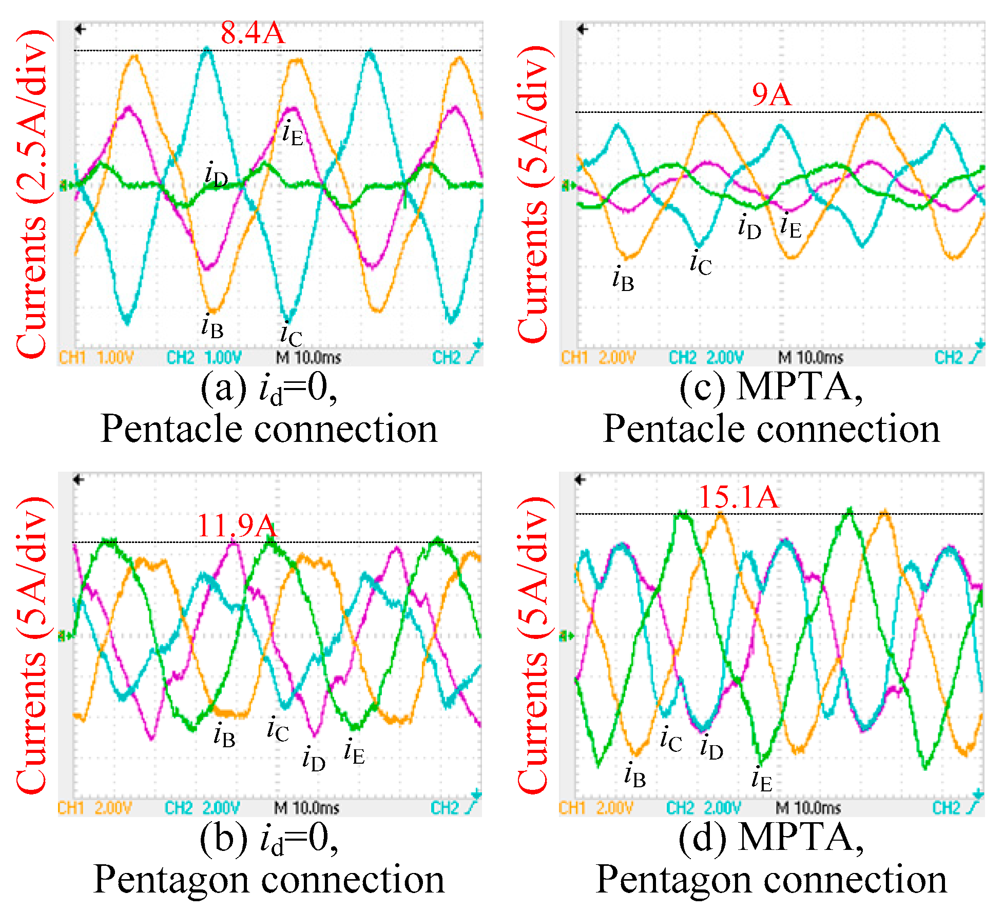
4.2. Open-Phase Fault

Figure 11 shows the waveforms of the winding phase currents under a single open- phase fault. For a penta-connection mode, a different control philosophy is used, rather than the previous star-control. From Figure 11a,b, both id and iq are well regulated, which confirms the effectiveness of the presented control scheme. On the other hand, iq3 under a pentagon-connection is rather small when the voltage of the q3-axis is subject to an open-loop control, and this implies iq3 can be well regulated without consuming too much harmonic power.
The control of MTPA contributes to the average torque, as evident in Figure 11c,d; however, iq3 increases a bit because of MTPA. When comparing with the d-q-q3 frame currents under a star-connection, as shown in Figure 8c, iq3 under a pentagon-connection is the smallest, which means a pentagon-connection mode can be a good choice for FTC.
Figure 12 refers to the profiles of the torque, ΔuA, and ZSCC under a single open-phase fault. From Figure 12a,b, the ZSCC can be remarkable for both pentacle- and pentagon-connection modes, and it interacts with the zero-sequence voltage, introducing additional torque ripples, which is one of the drawbacks of a penta-connection mode. From Figure 12c,d, the use of MTPA increases the torque ripple at the expense of maximizing the torque capacity. The ZSCC also increases in this procedure under pentacle-connection. On the contrary, the power spectrum of the ZSCC disperses to a high frequency under a pentagon-connection because of MTPA, and this implies the zero sequence components can be indirectly controlled with the use of line currents. On the other hand, ΔuA can be small relative to the case under a single-line open fault, and it illustrates that the omission of ΔuA, while modulating the line voltages, is in line with the expectation.
Figure 13 shows the waveforms of the actual winding phase currents under a single open-phase fault. Attributed to a considerable ZSCC, the remaining healthy phase currents are seriously imbalanced under a pentacle-connection, and a pentagon-connection mode necessitates a larger phase current to produce an identical average torque, which means the torque derating of the pentagon-connection mode is inferior to the pentacle-connection mode.
From Figure 13, even though the actual winding phase currents are seriously distorted with the ZSCC, they still manifest themselves as DCs under the presented transformation, and this enables the continuous use of the linear controller and paves its way to engineering practices. This also constitutes one of the main contributions of this work.

5. Conclusions

This work presents a unified fault-tolerant decoupling control for the star-, pentagon-, and pentacle-connected 5Φ-PMSMs. Single-line and -phase open faults are investigated, and key techniques to continuously use a previous decoupled model are elaborated. For a single open-line fault, the transformation of resistance, inductance, and the back-EMF from a penta-connection mode to a star-connection mode is desired, with the angular of vectorial control properly fixed. Concerning a single-phase open fault, voltage and current transformation from a line-to-neutral frame to a winding-oriented frame is suggested by taking care of the zero-sequence voltage and current.
Two FTC schemes, i.e., id = 0 to minimize the torque ripples and MTPA to maximize the torque capacity, are evaluated under all connection modes. The experimental results confirm the validity of the proposed unified control schemes, and simultaneously suggest that a pentagon-connection mode prevails under a single open-line fault for its small torque ripple and lower torque derating, and the star-connection mode takes the second place. However, with respect to the torque derating under an open-phase fault, the pentacle-connection mode performs best. Overall, under either an open-line fault or open-phase fault, the performance of a pentagon-connection mode is more balanced in terms of the harmonic current’s controllability; the ZSCC, torque derating, and torque ripple, and, therefore, this type of connection can find a bright future in engineering practices.
The saturation effect was not considered while performing the FTC, which may have affected the torque performance to some extent. For the practice of some more advanced controls, e.g., model predictive control and position sensorless control, this phenomenon should be incorporated. However, concerning fault-tolerant control, the saturation effect can be secondary to the zero-sequence circulating current. In the future, how to attenuate the zero-sequence current by regulating the remaining healthy phase currents deserves more investigation and will be addressed in our next phase.

Author Contributions

Conceptualization, B.T.; methodology, B.T. and R.L.; software, R.L. and J.H.; validation, R.L. and J.H.; formal analysis, R.L.; investigation, B.T.; resources, B.T.; data curation, B.T.; writing—original draft preparation, B.T. and R.L.; writing—review and editing, B.T. and R.L.; visualization, R.L. and J.H.; supervision, B.T.; project administration, B.T.; funding acquisition, B.T. All authors have read and agreed to the published version of the manuscript.

Funding

This research was funded by [Jiangsu Provincial Innovation and Entrepreneurship Doctor Program] grant number [JSSCBS20210175].

Institutional Review Board Statement

Not applicable.

Informed Consent Statement

Not applicable.

Data Availability Statement

Data available on request from the authors.

Conflicts of Interest

The authors declare no conflict of interest.

Appendix A

In this paper, suppose the stator is undamaged under an open-phase/line fault, and simultaneously, the iron core is unsaturated. Given this, the motor model in Figure 1 can still be presented by
[ u Aa u B u C u D u E ] = R [ i A i B i C i D i E ] + d d t ( [ L AA L AB L AC L AD L AE L BA L BB L BC L BD L BE L CA L CB L CC L CD L CE L DA L DB L DC L DD L DE L EA L EB L EC L ED L EE ] [ i A i B i C i D i E ] ) + [ e A e B e C e D e E ]
where Lxy, x = y = A, B, C, D, E, denotes the self- or mutual-inductance which possesses the following properties
L AA + L BA + L CA + L DA + L EA = L sum L AB + L BB + L CB + L DB + L EB = L sum L AC + L BC + L CC + L DC + L EC = L sum L AD + L BD + L CD + L DD + L ED = L sum L AE + L BE + L CE + L DE + L EE = L sum
with Lsum as an instantaneous quantity which is the function of the rotor position.
Regarding the back-EMFs, one can have
e A + e B + e C + e D + e E = 0
The actual phase currents obey following the rule
i A = 0 ,   i B + i C + i D + i E = i o
Note that herein iA, iB, iC, iD, and iE stand for the actual winding phase currents, rather than the observed ones, and io indicates the actual ZSCC.
Combining (A2)–(A4) with (A1) yields
u o = u Aa + u B + u C + u D + u E = R i o + d ( L sum i o )
From (A5), the zero-sequence voltage is associated with the ZSCC and is non-zero in a penta-wired system. The zero-sequence voltage reduces to the minimum while io is minimal.

References

  1. Sayed, E.; Abdalmagid, M.; Pietrini, G.; Sa’adeh, N.M.; Callegaro, A.D.; Goldstein, C.; Emadi, A. Review of Electric Machines in More-/Hybrid-/Turbo-Electric Aircraft. IEEE Trans. Transp. Electrif. 2021, 7, 2976–3005. [Google Scholar] [CrossRef]
  2. Zhao, W.; Cheng, M.; Chau, K.T.; Cao, R.; Ji, J. Remedial Injected-Harmonic-Current Operation of Redundant Flux-Switching Permanent-Magnet Motor Drives. IEEE Trans. Ind. Electron. 2013, 60, 151–159. [Google Scholar] [CrossRef]
  3. Sun, J.; Li, C.; Zheng, Z.; Wang, K.; Li, Y. A Generalized, Fast and Robust Open-Circuit Fault Diagnosis Technique for Star-connected Symmetrical Multiphase Drives. IEEE Trans. Energy Convers. 2022, 1. [Google Scholar] [CrossRef]
  4. Barrero, F.; Duran, M.J. Recent Advances in the Design, Modeling, and Control of Multiphase Machines—Part I. IEEE Trans. Ind. Electron. 2016, 63, 449–458. [Google Scholar] [CrossRef]
  5. Ghosh, B.C.; Habibullah; Ali, E. Performance Comparison of Five and Six Phase Induction Motors Operating under Normal and Faulty Conditions. In Proceedings of the 2019 4th International Conference on Electrical Information and Communication Technology (EICT), Khulna, Bangladesh, 20–22 December 2019; pp. 1–6. [Google Scholar] [CrossRef]
  6. Bensalem, Y.; Kouzou, A.; Abbassi, R.; Jerbi, H.; Kennel, R.; Abdelrahem, M. Sliding-Mode-Based Current and Speed Sensors Fault Diagnosis for Five-Phase PMSM. Energies 2022, 15, 71. [Google Scholar] [CrossRef]
  7. Ferreira, F.J.T.E.; Baoming, G.; Almeida, A.T.D. Stator Winding Connection-Mode Management in Line-Start Permanent Magnet Motors to Improve Their Efficiency and Power Factor. IEEE Trans. Energy Convers. 2013, 28, 523–534. [Google Scholar] [CrossRef]
  8. Cistelecan, M.V.; Ferreira, F.J.T.E.; Popescu, M. Adjustable Flux Three-Phase AC Machines with Combined Multiple-Step Star-Delta Winding Connections. IEEE Trans. Energy Convers. 2010, 25, 348–355. [Google Scholar] [CrossRef]
  9. Mavila, P.C.; Rajeevan, P. A Space Vector Based PWM Scheme for Realization of Virtual Pentagon, Pentacle Connections in open-end Winding Five Phase Machine Drives with Single DC Source. In Proceedings of the 2018 IEEE International Conference on Power Electronics, Drives and Energy Systems (PEDES), Chennai, India, 18–21 December 2018; pp. 1–6. [Google Scholar] [CrossRef]
  10. Abdel-Khalik, A.S.; Ahmed, S.; Elserougi, A.A.; Massoud, A. Effect of Stator Winding Connection of Five-Phase Induction Machines on Torque Ripples Under Open Line Condition. IEEE/ASME Trans. Mechatron. 2015, 20, 580–593. [Google Scholar] [CrossRef]
  11. Wang, P.; Gong, S.; Sun, X.; Liu, Z.; Jiang, D.; Qu, R. Fault-Tolerant Reconfiguration Topology and Control Strategy for Symmetric Open-Winding Multiphase Machines. IEEE Trans. Ind. Electron. 2022, 69, 8656–8666. [Google Scholar] [CrossRef]
  12. Yin, Z.; Sui, Y.; Zheng, P.; Yang, S.; Zheng, Z.; Huang, J. Short-Circuit Fault-Tolerant Control without Constraint on the D-Axis Armature Magnetomotive Force for Five-Phase PMSM. IEEE Trans. Ind. Electron. 2022, 69, 4472–4483. [Google Scholar] [CrossRef]
  13. Chen, Q.; Gu, L.; Wang, J.; Zhao, W.; Liu, G. Remedy Strategy for Five-Phase FTPMMs Under Single-Phase Short-Circuit Fault by Injecting Harmonic Currents from Third Space. IEEE Trans. Power Electron. 2022, 1. [Google Scholar] [CrossRef]
  14. Zhang, L.; Zhu, X.; Cui, R.; Han, S. A Generalized Open-Circuit Fault-Tolerant Control Strategy for FOC and DTC of Five-Phase Fault-Tolerant Permanent-Magnet Motor. IEEE Trans. Ind. Electron. 2022, 69, 7825–7836. [Google Scholar] [CrossRef]
  15. Wang, X.; Liu, G.; Chen, Q.; Farahat, A.; Song, X. Multivectors Model Predictive Control with Voltage Error Tracking for Five-Phase PMSM Short-Circuit Fault-Tolerant Operation. IEEE Trans. Transp. Electrif. 2022, 8, 675–687. [Google Scholar] [CrossRef]
  16. Wang, H.; Zhao, W.; Tang, H.; Tao, T.; Saeed, S. Improved Fault-Tolerant Model Predictive Torque Control of Five-Phase PMSM by Using Deadbeat Solution. IEEE Trans. Energy Convers. 2022, 37, 210–219. [Google Scholar] [CrossRef]
  17. Mohammadpour, A.; Parsa, L. A Unified Fault-Tolerant Current Control Approach for Five-Phase PM Motors With Trapezoidal Back EMF Under Different Stator Winding Connections. IEEE Trans. Power Electron. 2013, 28, 3517–3527. [Google Scholar] [CrossRef]
  18. Yepes, A.G.; Doval-Gandoy, J. Study and Active Enhancement by Converter Reconfiguration of the Performance in Terms of Stator Copper Loss, Derating Factor and Converter Rating of Multiphase Drives Under Two Open Legs with Different Stator Winding Connections. IEEE Access 2021, 9, 63356–63376. [Google Scholar] [CrossRef]
  19. Abdel-Khalik, A.S.; Ahmed, S.; Massoud, A.M. Steady-State Mathematical Modeling of a Five-Phase Induction Machine with a Combined Star/Pentagon Stator Winding Connection. IEEE Trans. Ind. Electron. 2016, 63, 1331–1343. [Google Scholar] [CrossRef]
  20. Masoud, M.I.; Abdel-Khalik, A.S.; Al-Abri, R.S.; Williams, B.W. Effects of unbalanced voltage on the steady-state performance of a five-phase induction motor with three different stator winding connections. In Proceedings of the 2014 International Conference on Electrical Machines (ICEM), Berlin, Germany, 2–5 September 2014; pp. 1583–1589. [Google Scholar] [CrossRef]
  21. Mohammadpour, A.; Sadeghi, S.; Parsa, L. A Generalized Fault-Tolerant Control Strategy for Five-Phase PM Motor Drives Considering Star, Pentagon, and Pentacle Connections of Stator Windings. IEEE Trans. Ind. Electron. 2014, 61, 63–75. [Google Scholar] [CrossRef]
  22. Tawfiq, K.B.; Ibrahim, M.N.; Sergeant, P. An Enhanced Fault-Tolerant Control of a Five-Phase Synchronous Reluctance Motor Fed from a Three-to-Five-phase Matrix Converter. IEEE J. Emerg. Sel. Top. Power Electron. 2022, 1. [Google Scholar] [CrossRef]
  23. Zaskalicky, P. Behavior of a Five-Phase Pentacle Connected IM Operated under One-Phase Fault. In Proceedings of the 2019 International Aegean Conference on Electrical Machines and Power Electronics (ACEMP) & 2019 International Conference on Optimization of Electrical and Electronic Equipment (OPTIM), Istanbul, Turkey, 27–29 August 2019; pp. 126–131. [Google Scholar]
  24. Masoud, M.I. Five phase induction motor: Phase transposition effect with different stator winding connections. In Proceedings of the IECON 2016-42nd Annual Conference of the IEEE Industrial Electronics Society, Florence, Italy, 23–26 October 2016; pp. 1648–1655. [Google Scholar]
  25. Abdel-Khalik, A.S.; Elgenedy, M.A.; Ahmed, S.; Massoud, A.M. An Improved Fault-Tolerant Five-Phase Induction Machine Using a Combined Star/Pentagon Single Layer Stator Winding Connection. IEEE Trans. Ind. Electron. 2016, 63, 618–628. [Google Scholar] [CrossRef]
  26. Zhou, H.; Zhao, W.; Liu, G.; Cheng, R.; Xie, Y. Remedial Field-Oriented Control of Five-Phase Fault-Tolerant Permanent-Magnet Motor by Using Reduced-Order Transformation Matrices. IEEE Trans. Ind. Electron. 2017, 64, 169–178. [Google Scholar] [CrossRef]
  27. Zhang, G.; Xiang, R.; Wang, G.; Li, C.; Bi, G.; Zhao, N.; Xu, D. Hybrid Pseudorandom Signal Injection for Position Sensorless SynRM Drives with Acoustic Noise Reduction. IEEE Trans. Transp. Electrif. 2022, 8, 1313–1325. [Google Scholar] [CrossRef]
  28. Tian, B.; An, Q.-T.; Duan, J.-D.; Sun, D.-Y.; Sun, L.; Semenov, D. Decoupled Modeling and Nonlinear Speed Control for Five-Phase PM Motor Under Single-Phase Open Fault. IEEE Trans. Power Electron. 2017, 32, 5473–5486. [Google Scholar] [CrossRef]
  29. Tian, B.; Sun, L.; Molinas, M.; An, Q.-T. Repetitive Control Based Phase Voltage Modulation Amendment for FOC-Based Five-Phase PMSMs under Single-Phase Open Fault. IEEE Trans. Ind. Electron. 2021, 68, 1949–1960. [Google Scholar] [CrossRef]
Figure 1. Stator winding connection modes.
Energies 15 03366 g001
Figure 2. Graphical illustration for a single open-line fault.
Energies 15 03366 g002
Figure 3. Graphical illustration for a single-phase open fault.
Energies 15 03366 g003
Figure 4. Block diagram of unified open-line fault-tolerant control for all connections.
Energies 15 03366 g004
Figure 5. Single open-phase fault in pentagon-connection mode.
Energies 15 03366 g005
Figure 6. Single open-phase fault in a pentacle-connection mode.
Energies 15 03366 g006
Figure 7. Block diagram of unified open-phase fault-tolerant control for all connection modes.
Energies 15 03366 g007
Figure 8. Waveforms of d-q-q3 frame current as well as the rotor speed under a single open-line fault.
Energies 15 03366 g008
Figure 9. Waveforms of ΔuA, io, Te, and θ under a single open-line fault.
Energies 15 03366 g009
Figure 10. Actual winding phase currents under a single open-line fault.
Energies 15 03366 g010
Figure 11. Waveforms of d-q-q3 frame currents and rotor speed under a single open-phase fault.
Energies 15 03366 g011
Figure 12. Waveforms of ΔuA, io, Te, and θ under a single open-phase fault.
Energies 15 03366 g012
Figure 13. Actual winding phase currents under a single open-phase fault.
Energies 15 03366 g013
Table 1. Prototype motor parameters.
SymbolDescriptionValue
λr1−ϕ1st order rotor flux0.17 Wb
λr3−ϕ3rd order rotor flux0.0062 Wb
RResistance per phase0.4 Ω
pPole Pairs2
Ldd-inductance of 1st subspace20.66 mH
Lqq-inductance of 1st subspace25.18 mH
IrRated phase current (rms)10 A
JRotor inertia0.1 kg·m2
nrRated speed1500 rpm
Publisher’s Note: MDPI stays neutral with regard to jurisdictional claims in published maps and institutional affiliations.

