Article

Research on a Limit Analytical Method for a Low-Speed Micro Permanent Magnet Torque Motor with Back Winding

1
School of Electrical and Electronic Engineering, Shandong University of Technology, Zibo 255000, China
2
Shandong Shanbo Electric Machine Group Co., Ltd., Zibo 255000, China
*
Author to whom correspondence should be addressed.
Energies 2022, 15(13), 4662; https://doi.org/10.3390/en15134662
Submission received: 27 April 2022 / Revised: 8 June 2022 / Accepted: 23 June 2022 / Published: 25 June 2022
(This article belongs to the Special Issue Advanced Permanent Magnet Machines and Drives)

Abstract

:
The conventional permanent magnet torque motor (PMTM) is slotted on the inner surface of the stator core. When the size of the stator core is small, the winding coils are difficult to embed into the slots. To solve the problem, a novel PMTM is presented, which is slotted on the outer surface of the stator core. As a result, the winding coils can be conveniently embedded into the slots from the outer surface of the stator core. The novel structure of the PMTM with back winding (BWPMTM) is introduced, and the advantage of the novel structure is analyzed. Furthermore, this paper proposes a limit analytical method to solve the optimal parameters of the motor which comprehensively considers four constraints: no-load back electromotive force (EMF), torque, temperature and slot space factor. The optimal parameters of the motor are directly solved to maximize torque density within the constrained range. This method avoids repeated iterative processes and greatly reduces the amount of calculation for PMTM design. Electromagnetic performance and thermal performance are analyzed based on the finite element model (FEM). Finally, the building of a prototype and the experimental results obtained with it are discussed. The rationality of the novel structure and the limit analytical method are verified.

1. Introduction

The PMTM can be directly connected to a load without a gearbox and can operate stably at low-speed or in locked-rotor conditions [1,2,3]. It has the merits of low-speed, high torque density, fast response speed, high precision control and small torque ripple and is widely used in many fields, such as aerospace, micro electric platforms and micro-robot joint and weapon equipment of artillery follow-up systems [4,5,6]. Therefore, many researchers have conducted in-depth studies on low-speed and large torque PMTMs.
With the development of industry, the demand for high-performance PMTMs has increased rapidly [7]. Research on low-speed and large-torque PMTMs focuses on torque ripple and torque density. Cogging torque is the important part of torque ripple. Due to the interaction between the permanent magnet and the stator teeth, cogging torque is inevitably present which can affect the running performance of a PMTM. At present, researchers have carried out a lot of work on weakening cogging torque, mainly including the following measures: magnet skewing [8,9], slot skewing [10], asymmetric windings [11], magnetic wedges filling stator slots, etc. Cogging torque reduction by optimizing the shape of permanent magnets was presented in [12,13]. The study reported in [14] applied 1J22 soft magnetic alloy to a PMTM and proposed a multi-objective optimization method based on a non-dominant sorting genetic algorithm II to improve motor performance, which was applied to the optimal design of surface mount permanent magnet synchronous motors. The simulation results showed the effectiveness of this method. In [15], a low-speed and high-torque dual-stator permanent magnet direct drive motor was proposed, which could improve the torque density at the same the motor volume. In [16], various cogging torque suppression methods were proposed, the relationship between cogging torque and structural parameters was derived by formulas and the torque distortion caused by armature reaction force was predicted. In [17], a permanent magnet slotting machine with a special tooth tip structure was introduced, which could effectively reduce magnetic leakage and armature reaction to improve motor performance, while [18] proposed a technique to increase torque density by changing the shape of the permanent magnet with the minimum magnet volume. Increasing the PM thickness more than the width increased torque density. In [19], a multi-objective optimization method to determine the optimization target by analyzing the factors that affect torque ripple was proposed. The existing analysis methods improve torque based on the baseline motor or by determining motor size. The design process for the size of the prototype was not described. Hence, this paper proposes a limit analytical method to maximize the torque density of the motor by the stack length based on the torque and other indicators. The design process for solving motor parameters is given in this paper.
In this study, a PMTM is proposed which is slotted on the outer surface of the stator core. It solves the problem of embedding winding when the stator inner diameter is small. In addition, this paper proposes a limit analysis method which can quickly find the optimal parameters that meet all the constraints. Finite element software was used to build the model. The simulation results verify the rationality of the novel structure and the limit analysis method.

2. Structure and Advantage Analysis of the BWPMTM

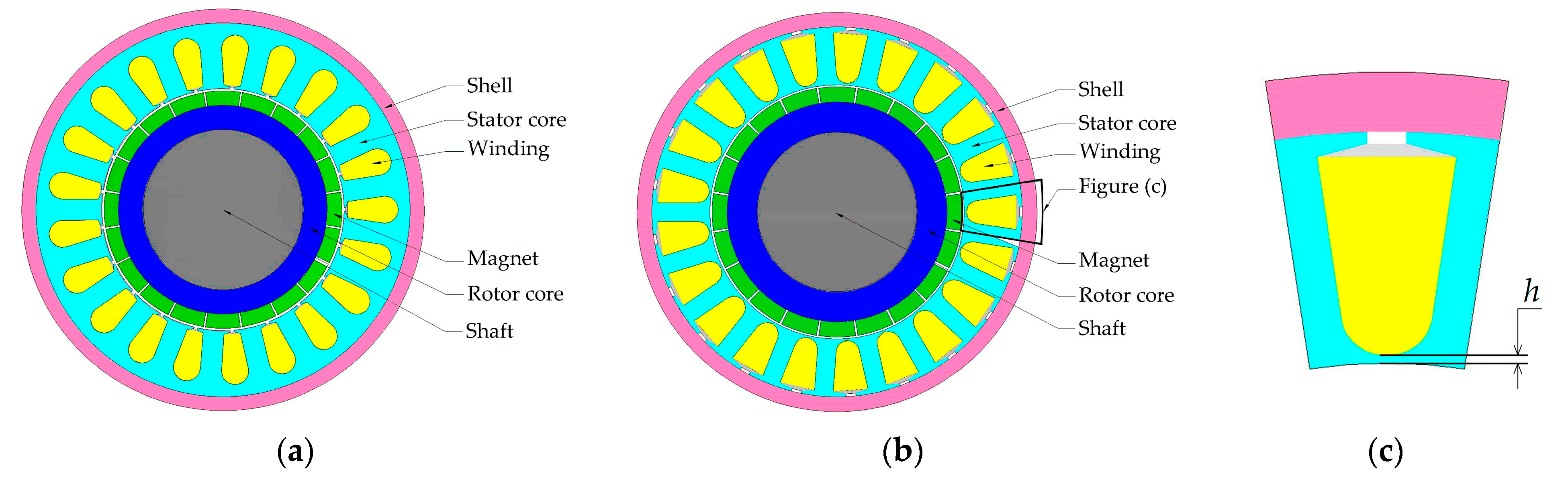
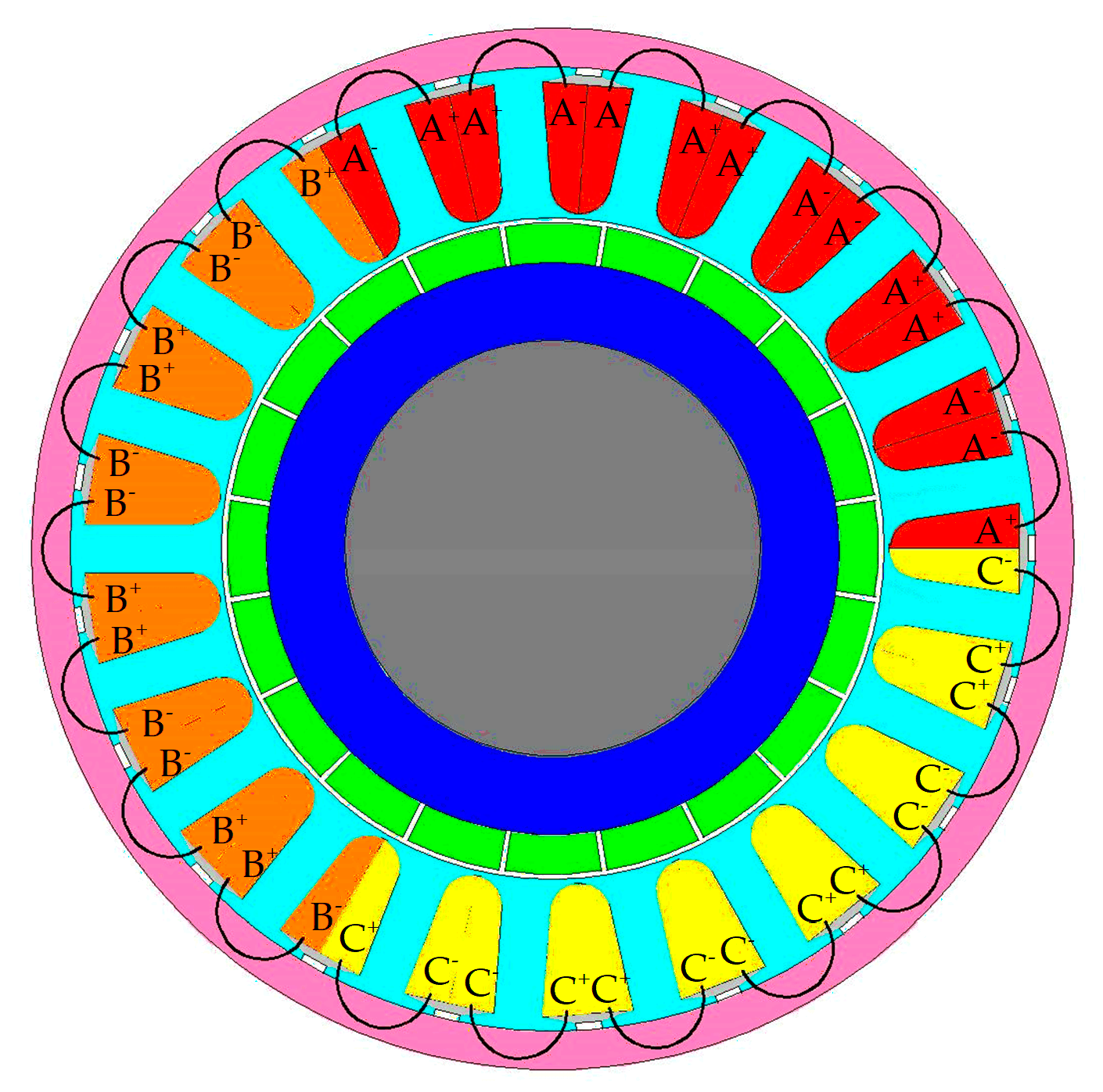
2.1. Motor Structure

There are two common embedding winding methods: automatic embedding by an embedded robot and artificial embedding. The conventional PMTM is slotted on the inner surface of the stator core, as shown in Figure 1a. It is difficult to pass the embedded robot through the inner hole of the stator when the stator inner diameter is less than 40 mm. Artificial embedding is also extremely difficult. In view of this problem, a novel structure of PMTM is proposed, which is slotted on the outer surface of the stator core. With the novel structure, winding coils can be simply embedded into the slot from the outer surface of the stator core by the above two methods, with high productivity and efficiency and low production cost. The main magnetic flux path of the conventional PMTM is: permanent magnet, air gap, stator tooth, stator yoke. On account of slotting on the outer surface of stator, the novel stator structure has no yoke. In order to close the magnetic flux lines to form a loop, the shell is made of a high-permeability material as a part of the magnetic circuit. So, the main magnetic flow path of the BWPMTM is permanent magnet, air gap, stator tooth, shell. The eddy loss in the shell is tiny and can be ignored under low-speed or locked-rotor conditions. Therefore, the novel structure is suitable for micro PMTM, with an inner diameter for the stator less than 40 mm, working under low-speed or rocked-rotor conditions. Fractional slot concentrated winding was used in this study because of its advantages of high torque density and high slot filling coefficient [20].
The slot type of the BWPMTM is equivalent to the closed slot, which can effectively reduce the torque ripple and improve the running performance [21,22]. As shown in Figure 1c, there is a magnetic barrier (the connection between the bottom of the slot and the inner surface of the stator) to maintain the integrity of the stator. The magnetic barrier will increase the magnetic leakage. Therefore, the mechanical strength of the magnetic barrier and the electromagnetic performance of the motor should be comprehensively considered for the magnetic barrier thickness h in the design.

2.2. Fractional Slot Concentrated Winding

The slot number of per phase per pole of fractional slot concentrated winding is a fractional number. Compared with the integer slot permanent magnet motor, the fractional slot concentrated winding permanent magnet motor has the following advantages: greatly shortened end length, effectively reduced copper weight and copper loss, improved efficiency and power density and the winding coefficient of the fundamental wave of the magnetomotive force is high. The winding coefficient can be more than 0.93 by selecting the appropriate pole–slot combination; improvement of the slot space factor helps improve the power density; and the cogging torque can be effectively restrained by selecting a reasonable pole–slot combination [23,24]. Based on the above advantages, the pole–slot combination of 20 poles and 22 slots is adopted in this paper. The spatial distribution diagram of the three-phase winding motor is shown in Figure 2:
As can be seen from the figure above, the three phases of the motor are distributed centrally in space with differences of 120 degrees. Since the pitch of the motor is 1, there is no need to consider the starting position when winding. In addition, there is no part for the three-phase winding to cross, so the winding can be made into a type in advance and directly embedded in the stator slot.

2.3. Advantage in Torque Density

The general equation of AC motor electromagnetic torque can be expressed as:
T e = π 2 p 2 F Φ F = 2 m N a K w π p I
where p is the number of pole pairs; F is the amplitude of magnetomotive force; Φ is air gap flux, Φ = 2 B τ L / π ; B is the amplitude of air gap flux density; τ is pole pitch; L is the stack length; N a is the number of series turns per phase; K w is the winding factor; and I is the phase current.
The number of ampere conductors per unit of the armature circumference is called the electric load, A .
A = 2 m N a I π D
where D is the stator inner diameter.
Substitution of I of Equation (2) in Equation (1) yields the torque equation, shown as:
T e = π K w A B D 2 L 2 2
It can be seen that the torque is proportional to the product of the stator inner diameter squared and the stack length. The BWPMTM is slotted on the outer surface of the stator without the stator yoke. A larger stator inner diameter can be obtained in the novel structure. Based on the same shell outer diameter, the larger the stator inner diameter, the shorter the stack length, the lighter the weight of the motor and the higher the torque density. Hence, a higher torque density can be obtained theoretically.

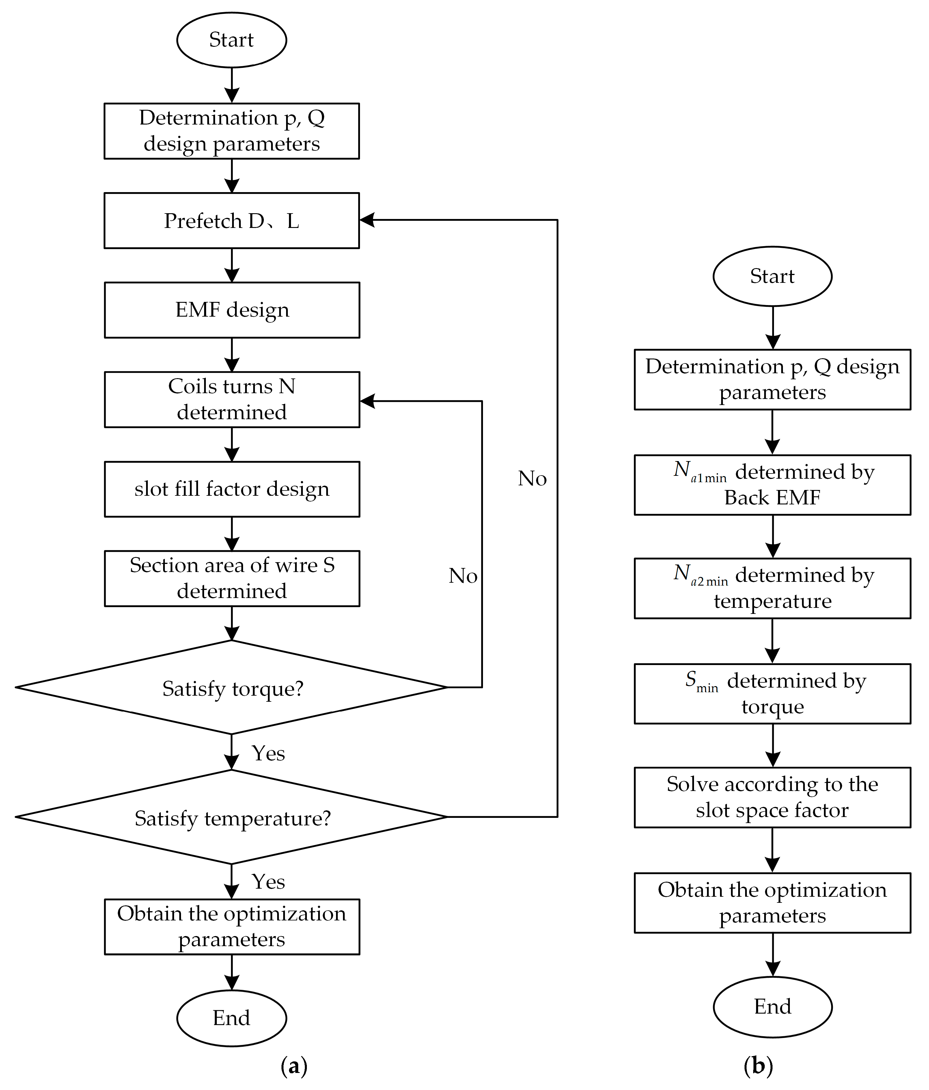
3. Limit Analytical Method

The design flow chart of the traditional analytical method is shown in Figure 3a. Firstly, the traditional design of the motor determines the number of pole pairs p and number of slots Q and prefetches the stator inner diameter D and the stack length L according to experience. Then, the number of series turns per phase are obtained according to the no-load back EMF as well as the section area of single wire according to the slot space factor. Finally, the motor parameters are obtained by judging whether the torque and temperature constraints are met, otherwise the parameters should be re-calculated. However, the motor parameters obtained by the traditional method may not be optimal to satisfy all constraints. The traditional design method requires multiple iteration calculations, which take a large amount of calculation and consume a lot of manpower and time. This paper proposes a limit analytical method, as shown in Figure 3b, which can locate the optimal parameters accurately and avoid iterative calculation. The design is divided into four steps. In the first step, the minimum number of the number of series turns per phase N a 1 min is obtained according to the no-load back EMF. In the second step, the minimum number of the number of series turns per phase N a 2 min is obtained according to the maximum permissible temperature. In the third step, the minimum number of the section area of single wire S min is obtained according to the locked-rotor torque. In the last step, the optimal parameters of the motor are obtained by integrating the relationship between constraints and judging by the slot space factor. This design method avoids the iterative calculation of parameters and models, which is beneficial in terms of saving labor and time costs.
The limit analytical method proposed in this paper is used to obtain the maximum torque density of the motor under the design specifications. The specifications of the BWPMTM are listed in Table 1.
According to the theory of electromechanics, the magnetic field energy mainly exists in the air gap, and the electromechanical energy conversion is mainly carried out through the air gap. Practice shows that the stator inner diameter and the stack length near the air gap are the main parameters of the motor. The product of the square of the stator inner diameter and the stack length can be determined using Equation (4):
D 2 L = 2 2 T e π K w A B
The maximum torque density can be obtained at the minimum axial length based on constant shell outer diameter. As a result, taking the minimum stack length as the objective function to solve the optimal parameters of the motor is an effective method.

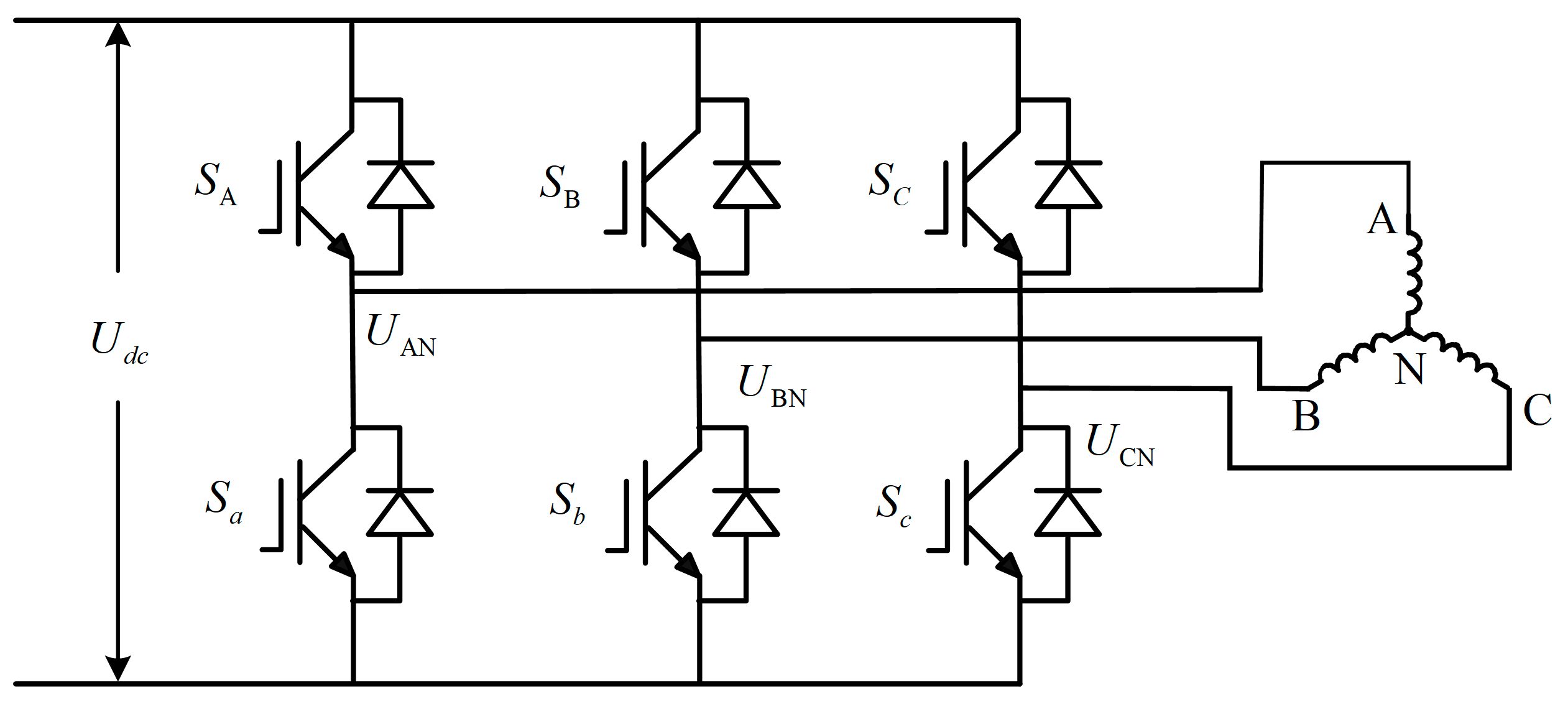
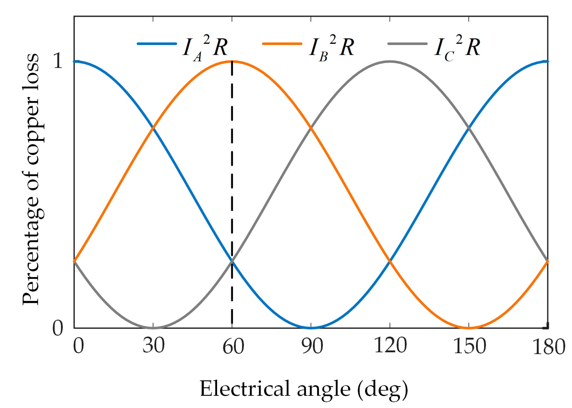
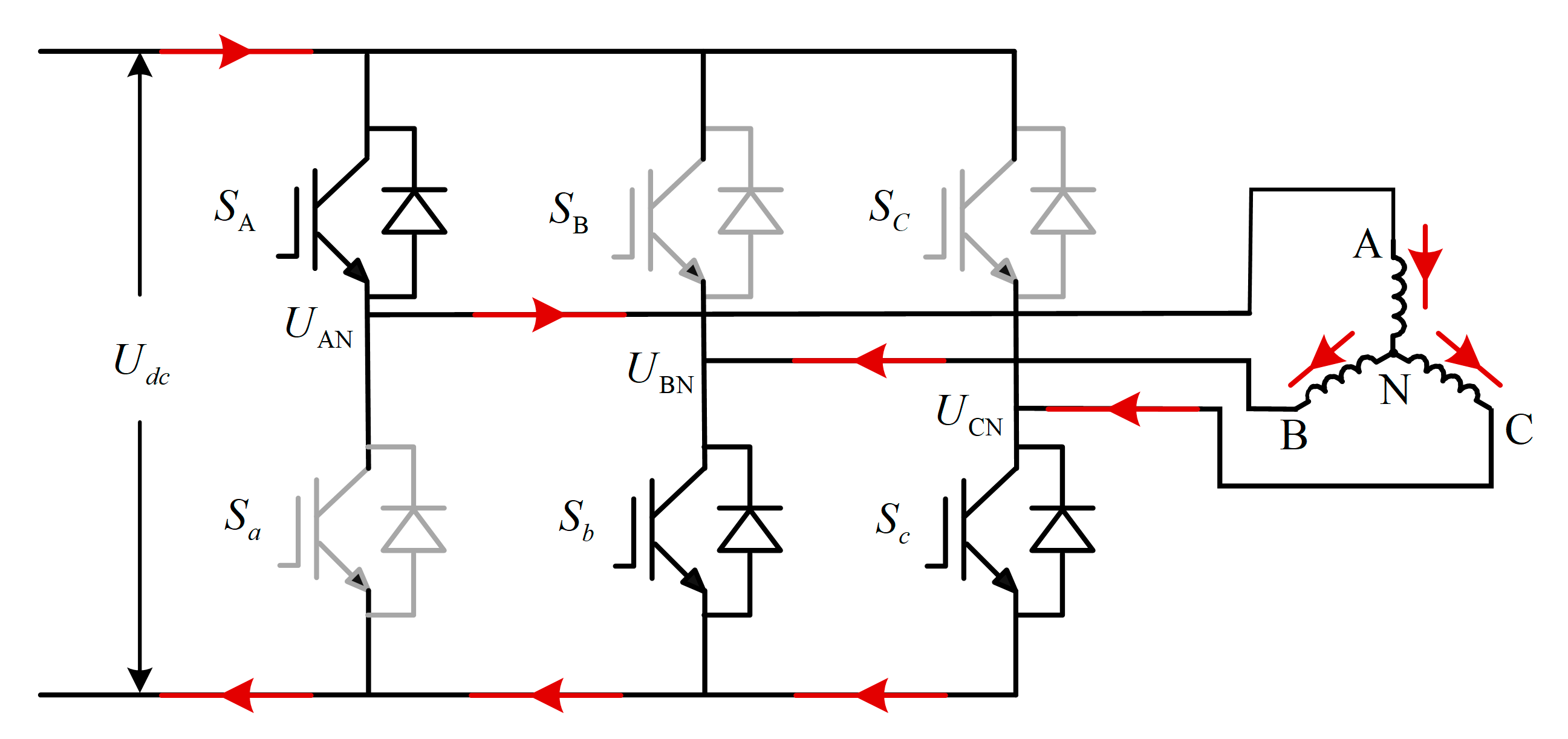
3.1. The Control Circuit of the Motor

Space vector pulse width modulation (SVPWM) technology is applied to the control system of the PMSM. Based on flux linkage tracking, SVPWM technology combines inverters and the PMSM [25]. The actual voltage space vector is synthesized by using different combinations of six bridge arms switching signals to generate eight basic space voltage vectors, and the rotation trajectory of the resultant vector forms the basic flux circle. Based on SVPWM technology, direct current U d c can be converted to alternating current U AN , U BN and U CN and applied to the three-phase winding motor. The control circuit of motor is shown in Figure 4.

3.2. Constraint of No-Load Back EMF

Assuming that the magnetic field is sinusoidally distributed in the air gap, the phase EMF can be expressed as:
E = 2 π k σ K w f N a Φ
where f is the electric frequency, which is proportional to the speed.
It can be seen from Equation (5) that the EMF is proportional to the air gap magnetic flux. From the above, the magnetic barrier will increase the magnetic flux leakage, resulting in a decrease in air gap flux, which leads to a decrease in the EMF. Thus, it is necessary to multiply the coefficient k σ ( k σ < 1 ) in the process of calculating the EMF to reflect the influence of the magnetic flux leakage on the magnetic bridge.
The voltage balance equation of the motor on no-load can be written as:
U P N = E + R I
where U P N is the rated phase voltage, E is the phase EMF and R is the phase resistance.
When the motor is running under no-load condition, the current is nearly 0 A, so the no-load back EMF is approximately equal to the rated phase voltage. If the running speed reaches the maximum no-load speed and the no-load back EMF is less than the rated phase voltage, the motor speed will continue to increase until the two are equal. Meanwhile, the motor running speed exceeds the specified maximum speed, which will cause a great burden to the motor operation and even cause damage. Therefore, the no-load speed of the no-load back EMF at the rated phase voltage must be lower than the maximum allowable speed, i.e., n n max . Incorporating the inequality into Equation (5), the constraint of the number of series turns per phase can be expressed as:
N a N a 1 min = 60 E 2 π k σ K w B D L n max  

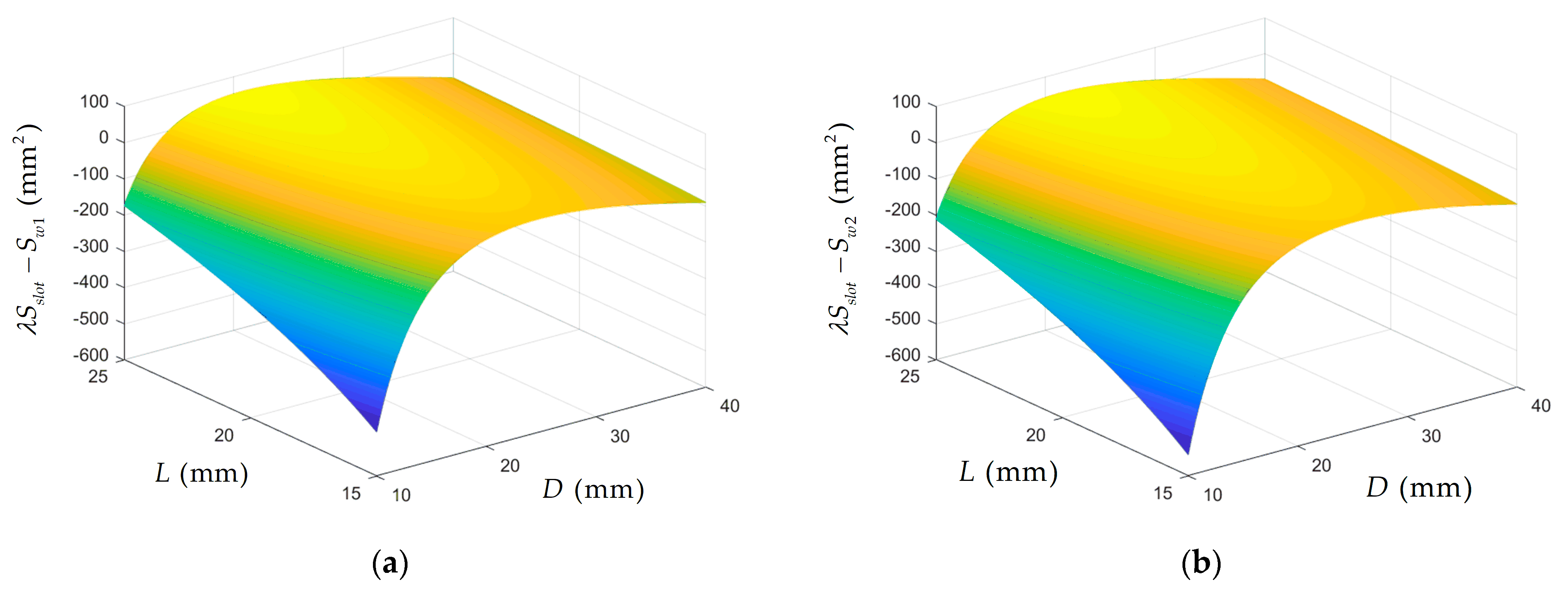
3.3. Constraint of Slot Space Factor

The slot space factor is the ratio of the section area of bare copper of the winding wire to the stator slot section area, and a reasonable slot space factor is one of the specifications of the motor design. Generally, the slot space factor of the PMTM is less than 0.3, considering the manufacturing process. For the BWPMTM, the winding coil is embedded in the slot from the outer surface of the stator, simplifying the manufacturing process. Therefore, the slot space factor can be improved.
In this paper, in the stator with parallel teeth, the section area of the stator slot can be approximately expressed as:
S s l o t = π D 2 2 D 1 2 4 Q b t D 2 D 1
where S s l o t is the slot section area, D 2 is the stator outer diameter, D 1 is the slot bottom diameter and b t the width of the stator teeth.
The slot space factor is used to judge whether the area of winding wire is adequate. The section area of winding wire needs to meet the constraint:
S w λ S s l o t S w = 2 m N a S
where, λ is the slot space factor, S w is the section area of bare copper of all winding wires and S is the section area of bare copper of a single wire.

3.4. Constraint of Temperature

To improving the utilization of motor material, higher electromagnetic load is often adopted, but most motors adopt natural cooling, which leads to poor heat dissipation conditions and makes the temperature rise problem for the motor more prominent. Excessive temperature of the motor can reduce the performance of motor material, e.g., leading to a decline in the magnetic properties of silicon steel sheets as well as the electrical conductivity of the winding. Hence, the temperature analysis is a significant part of motor design.
The instantaneous value of the three-phase current before the rotor of the motor is locked is as follows:
I A / B / C = I m cos ( θ + α )
where θ is the electrical angle; α is the initial position angle, corresponding to the A-phase, B-phase and C-phase, which are 0°, −120° and 120°, respectively; and I m is the amplitude of the phase current.
According to the voltage balance equation, the back EMF is 0 under the locked-rotor condition. Therefore, the winding current is the largest, the greater the loss of the motor, and the highest temperature of the motor. In addition, the motor designed in this study has the longest time under the locked-rotor condition, so this paper takes the locked-rotor condition as an example to design.
When the motor works under the locked-rotor condition, the speed is 0 rpm. Meanwhile, the motor has no core loss, only the winding copper loss.
P c u = P c u A / B / C = I A 2 R + I B 2 R + I C 2 R = I m 2 R ( cos ( θ ) 2 + cos ( θ 2 π 3 ) 2 + cos ( θ + 2 π 3 ) 2 ) = 3 2 I m 2 R
The total copper loss is a constant value, which is independent of the locked-rotor position. However, the distribution of the copper loss is not constant. With the change of the locked-rotor position, the distribution of the copper loss is different, resulting in a difference in the temperature distribution and in the maximum temperature. The maximum temperature caused by the same copper loss is basically the same given that the stator outer diameter is constant, the stack length does not change much and the heat dissipation conditions are the same.
It can be seen form Figure 5 that the copper loss in the three-phase windings is a function of the square of the sine. The copper loss of the A-phase winding reaches the maximum value at θ = 0 ° , and the copper loss of the B-phase winding reaches the maximum value at θ = 60 ° . At these two positions, the winding copper loss distribution regularity is the same and only differs by 120° in the space position. In consequence, the maximum temperature of the motor is the same. The maximum temperature occurs cyclically with an electrical angle of 60°. According to the symmetry of the loss distribution, the copper loss can be calculated using electromagnetic field simulation software at the four locked-rotor positions θ = 0 ° , θ = 10 ° , θ = 20 ° and θ = 30 ° and loaded into the temperature field as a heat source. As can be seen form the results of temperature field simulation, the motor has a maximum temperature in the A-phase winding at the locked-rotor position θ = 0 ° , that is, the copper loss of the A-phase winding is the maximum. The temperature of the B-phase and the C-phase are the same according to symmetry when the temperature of the A-phase winding is the highest. The copper loss of the A-phase winding is four times that of the B-phase winding or the C-phase winding. According to Figure 2, when the A-phase winding loss is the largest, the heat source is mainly distributed on the A-phase winding in the temperature field simulation. Due to the concentrated distribution of the A-phase winding in space, the temperature of the motor at the position of the A-phase winding is higher than that of the B-phase winding and the C-phase winding. At this point, it is the maximum blocking position of the motor operation. As long as the maximum temperature meets the requirement at the locked-rotor position θ = 0 ° , the maximum temperature meets the requirement, regardless of the locked rotor at any position.
At this point, switching tubes S A , S b and S c are normally on. The voltage source acts directly on the three-phase winding motor. Therefore, this paper studies the limit design under the condition of the locked-rotor position θ = 0 ° , which is not affected by the control method. The current flow path is shown in Figure 6.
Ignoring the pressure drop on the switching tube, the winding current can be expressed as:
I m = 2 U d c 3 R
where U d c is the bus voltage; R is the phase resistance, which includes the winding resistance within the core, R e f , and the end winding resistance, R e n d .
R = R e f + R e n d = 2 ρ N a L S + ρ N a L e n d S
where ρ is the copper resistivity and L e n d is the end winding length, which can be approximated by the tooth pitch when the motor size is small and the concentrated winding is adopted.
Calculate the maximum copper loss at the locked-rotor position θ = 0 ° with the continuous locked-rotor voltage for 10 min and the peak locked-rotor voltage for 1 min while the motor reaches the maximum allowable temperature. That the copper loss is less than the maximum loss calculated above can ensure that the maximum temperature is within the allowable range.
P max 3 2 I m 2 R
Substitution of Equations (12) and (13) in Equation (15) yields the constraint of the number of series turns per phase:
N a N a 2 min = 2 U 2 S 3 ρ 2 L + L e n d P max

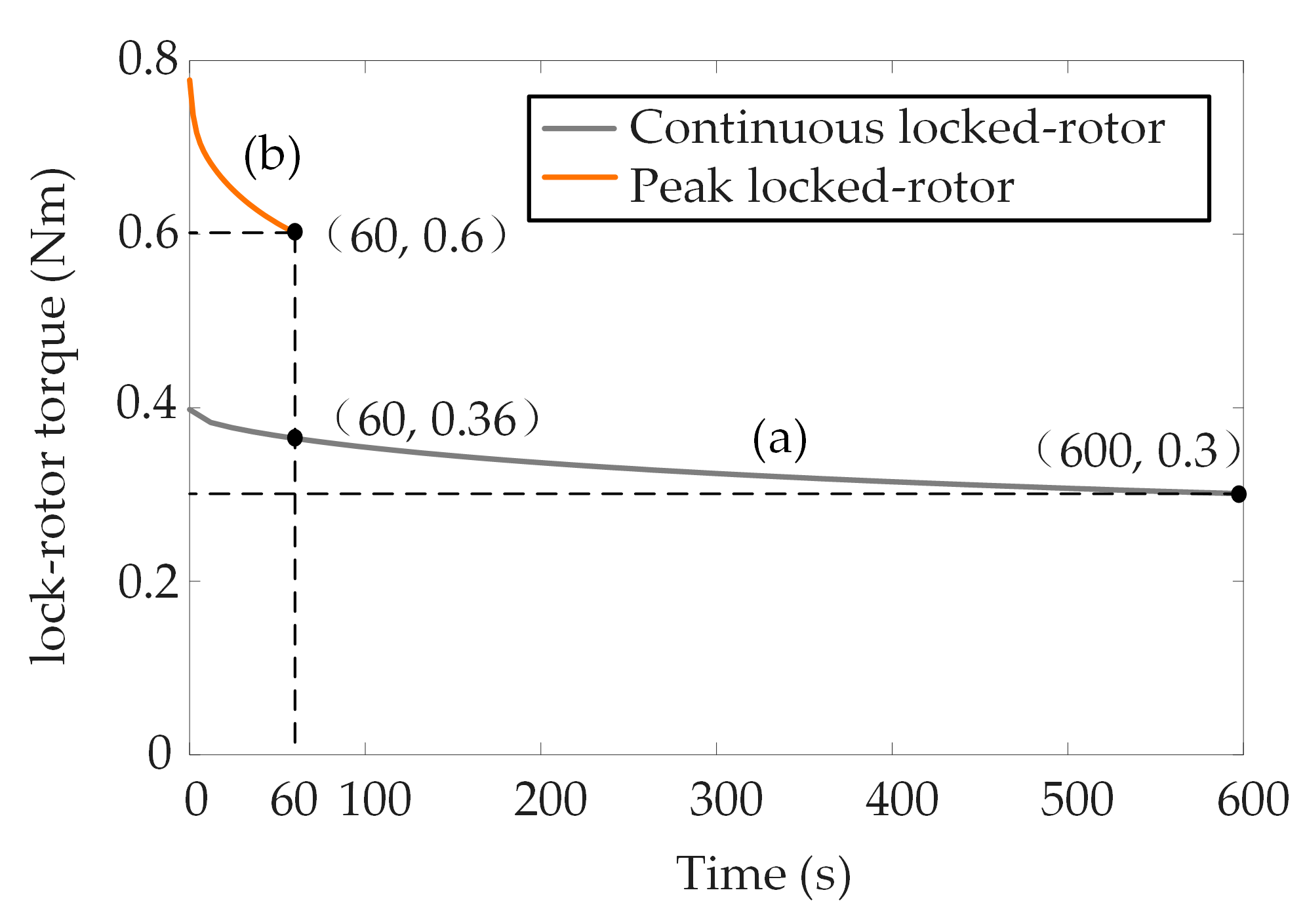
3.5. Constraint of Torque

When the motor runs under the locked-rotor condition, the back EMF is zero, the winding inductance is zero and the armature current is a direct current. Hence, the bus voltage acts entirely on the winding resistance, resulting in an increase in copper loss and severe heating of the winding coil. As the resistance tends to increase as temperature increases and the torque tends to decrease as the resistance increases, the influence of temperature on the torque should be considered in the design process. It is necessary to ensure that the torque meets the design requirement at the maximum temperature. From the above analysis, the motor has the maximum temperature as the current of the A-phase winding reaches the maximum value (a case of the A-phase). Phases B and C have the same temperature distribution. Considering the effect of temperature, the phase resistance can be expressed as:
R A = T A + 235 T 0 + 235 R = k 1 R R B / C = T B + 235 T 0 + 235 R = k 2 R
where T 0 is the initial temperature and T A and T B are the temperatures of the A-phase winding and the B-phase (C-phase) windings, respectively.
Substitution of Equation (17) in Equation (1) yields the torque considering the temperature:
T e = m K w B D L U S ρ ( 2 k 1 + k 2 ) ( 2 L + L e n d )
The torque considering the temperature should be greater than the rated torque, T e N . The torque is proportional to the section area of wire. It can be determined that the cross-section of the wire needs to meet the following constraint:
S S min = ρ ( 2 k 1 + k 2 ) ( 2 L + L e n d ) m K w B D L U T e N  

3.6. Design of the Magnetic Barrier

When the motor works under the locked-rotor condition for a long time, the frequency of the motor is zero, so the influence of silicon steel sheet thickness on core loss can be negligible. A silicon steel sheet thickness with a specification of 0.5 mm was selected considering the cost. The design of the magnetic barrier must not only meet the requirement of mechanical strength but also consider electromagnetic performance.
  • The magnetic barrier should be as small as possible so that the magnetic flux at the slot bottom is in a state of oversaturation. This allows magnetic flux to pass through the stator teeth to the greatest extent possible, reducing magnetic leakage and improving the efficiency of the permanent magnet.
  • The thickness of the stator stamping die is generally larger than 0.15 mm–0.2 mm in the manufacturing process. In view of the wear of the die on the stamping die and the service life of the stamping die, h = 0.2   mm is selected. The maximum force that the slot bottom bears can be expressed as F max = P L s h , where P is the yield strength and L s is the thickness of the silicon steel sheet. To ensure the safe operation of the motor, it is taken to be 50% of the yield strength of the silicon steel sheet for the purpose of calculation. The force that the magnetic barrier bears during processing is less than F max .

3.7. The Solution of Optimal Parameters

From the above, the constraints of the no-load back EMF, temperature and torque are transformed into the constraints of the number of series turns per phase and the cross-section of the wire. According to the minimum number of series turns per phase and the minimum cross-section of the wire, the minimum section area of all winding wires can be obtained.
S w 1 = 2 m N a 1 min S min = 2 m 60 E 2 π k σ K w B D L n max ρ ( 2 k 1 + k 2 ) ( 2 L + L e n d ) m K w B D L U T e N = 60 2 ρ E T e N ( 2 k 1 + k 2 ) ( 2 L + π D Q ) π k σ K w 2 B 2 D 2 L 2 U n max
S w 2 = 2 m N a 2 min S min = 2 m 2 U 2 3 ρ P max 2 L + L e n d S min 2 = 4 ρ T e N 2 ( 2 k 1 + k 2 ) 2 ( 2 L + L e n d ) 3 m P max K w 2 B 2 D 2 L 2
where S w 1 is the section area of all winding wires satisfying the constraints of the no-load back EMF and temperature increase and S w 2 is the winding section satisfying the constraints of the torque and temperature increase.
Then, the optimal parameters of the motor can be obtained by judging whether the winding wires can be reasonably placed in the stator slot under the constant of shell outer diameter D s = 40 mm .
λ S s l o t S w 1 0  
λ S s l o t S w 2 0
As can be seen from Figure 7, both λ S s l o t S w 1 and λ S s l o t S w 2 increase with increase in L , which first increases then decreases with increase in D . The minimum value of L that satisfies the Equation (22) is 17.1 mm, and D ranges from 23.2 mm to 24.7 mm. The minimum value of L that satisfies Equation (23) is 17.6 mm, and D ranges from 23.2 mm to 24.8 mm. Leaving a certain margin for the stator inner diameter considering the wire size, take D = 24.6 mm and L = 18 mm . The value range of N and S can be obtained by Equations (7), (16) and (19). Within the range, the maximum resistance is preferred to minimize the temperature increase.
The parameters of the BWPMTM are shown in Table 2.

4. Simulation Results and Discussion

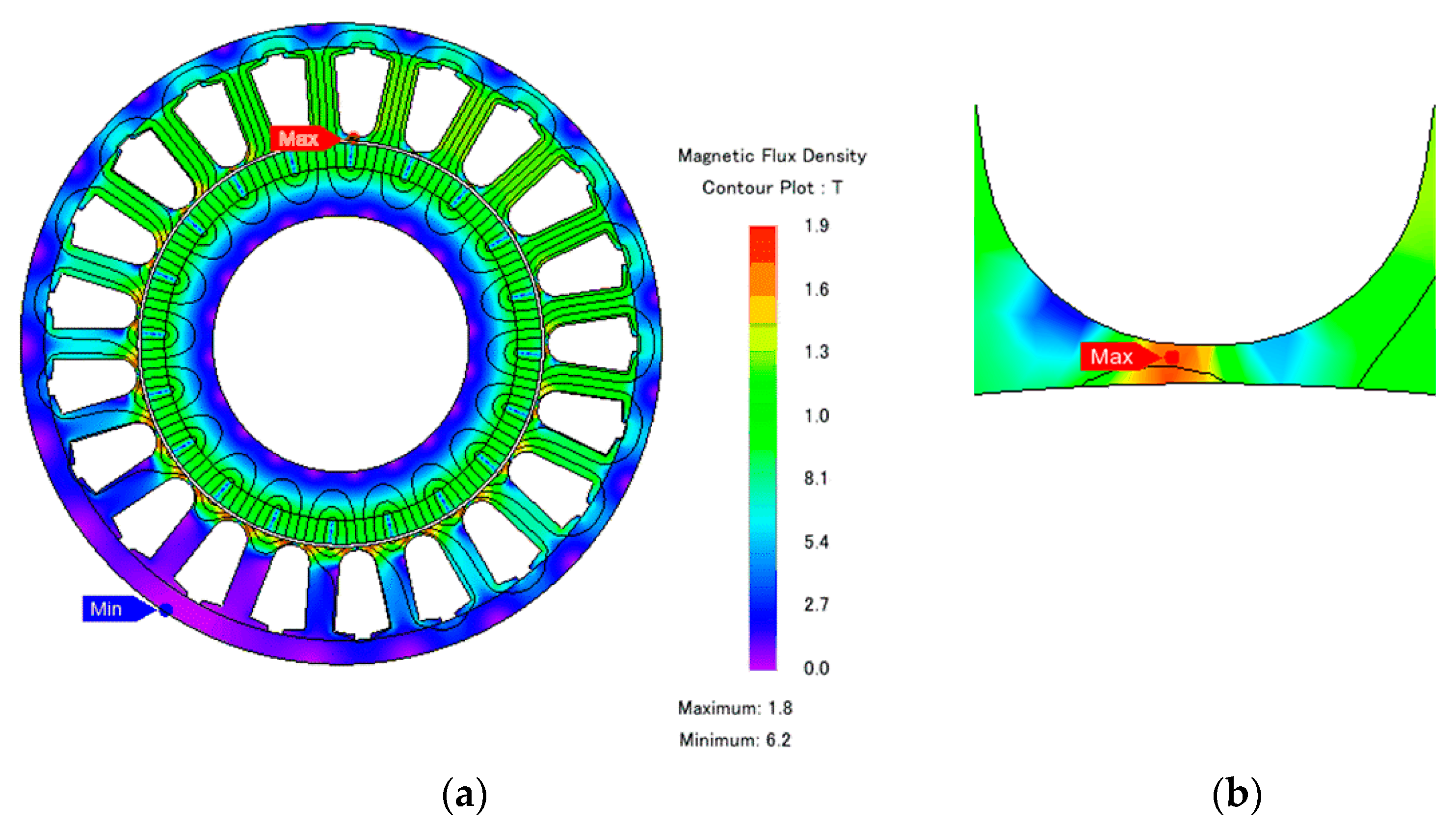
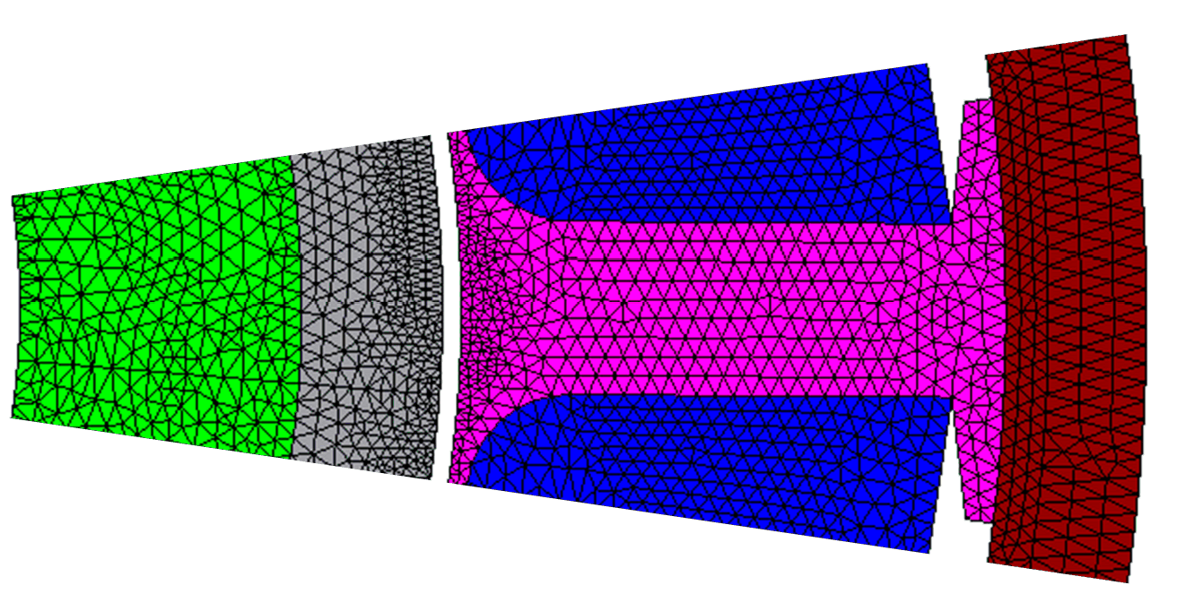
4.1. Finite Element Model

The finite element numerical calculation of the electromagnetic field has the advantages of accurate calculation, flexible meshing and can better deal with nonlinear problems, which make it suitable for solving the problem of complex geometric shapes, such as a motor has. It is widely used in the analysis of and calculations for various motors.
The process of using finite element software to establish a motor model can be divided into the following steps: according to the size of the motor, draw the motor model; determine the material properties of the motor; determine the boundary conditions; determine the meshing; then set the load and solve the matrix.
Firstly, with the parameters in Table 2, the model of the BWPMTM was drawn based on the finite element software. Secondly, the default boundary condition was automatically added to the outer boundary of the object during the solution process. With two objects in contact, the tangential component of the magnetic field intensity H and the normal component of the magnetic induction intensity B remain continuous at the contact surface. The vector potential boundary condition is mainly applied to the edge of the solution domain or the calculation model, and all points on the edge can be defined to satisfy the following two formulas:
A z = C o n s t   or   r A θ = C o n s t
where the former applies to the Cartesian coordinate system and the latter to the cylindrical coordinate system, Const is a given constant, and A z and A θ are the vector magnetic potential in the Z direction in the Cartesian coordinate system and the vector magnetic potential in the θ direction in the cylindrical coordinate system, respectively.
Thirdly, the material in the finite element software can be divided into air, magnetic material, conductive material and permanent magnet material. In modeling, corresponding materials are added to the different parts. They can be selected from the material library or according to the material properties of their own inputs. The material properties of the stator rotor are shown in Table 3 and added to the corresponding motor parts. The stator core and rotor core are added with silicon steel sheet material. The shell is added with Steel c101.
In addition, the meshing is the basis of finite element solution. Manual division is needed to ensure the accuracy of the calculation. The mesh is finer in the part where the magnetic field is strong or the magnetic field varies greatly. The mesh within a pitch is copied and rotated to ensure that the stator under different poles has the same mesh. The finite element mesh generation result within one pitch is shown in Figure 8.
Finally, according to the design requirements, to set different excitations and loads, solve the matrix and solve the analysis.

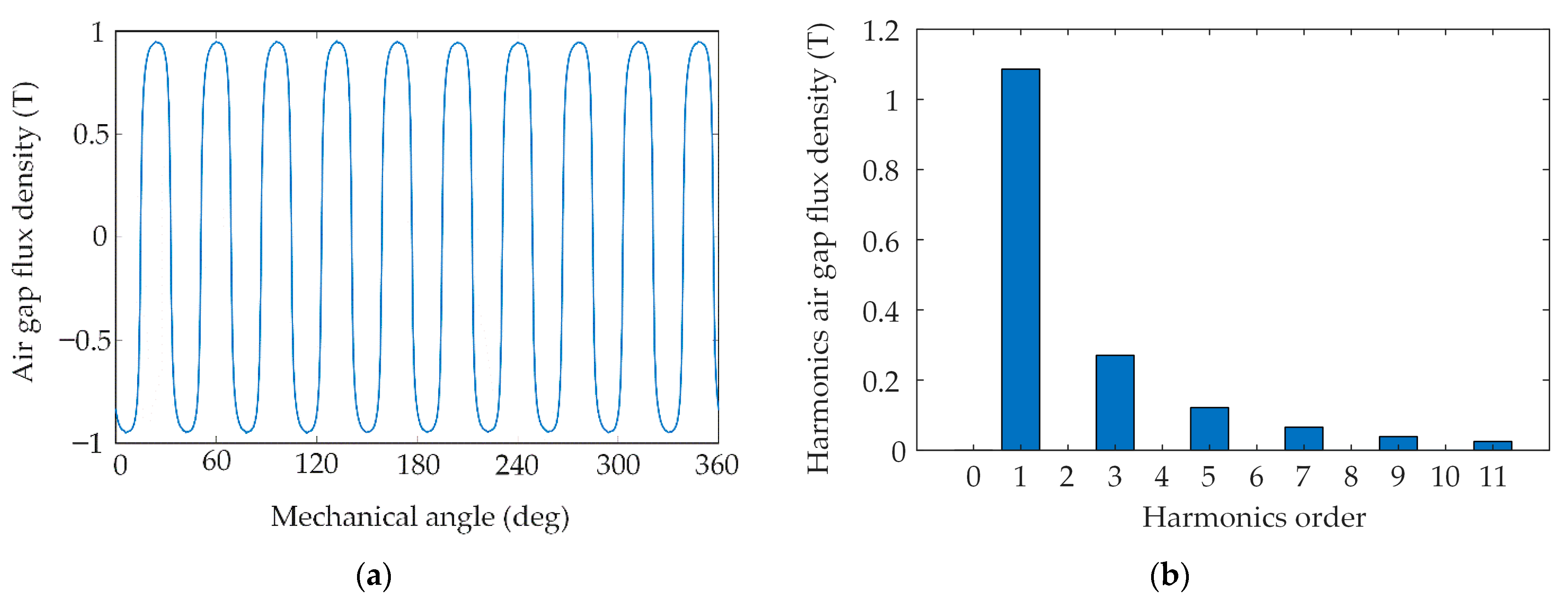
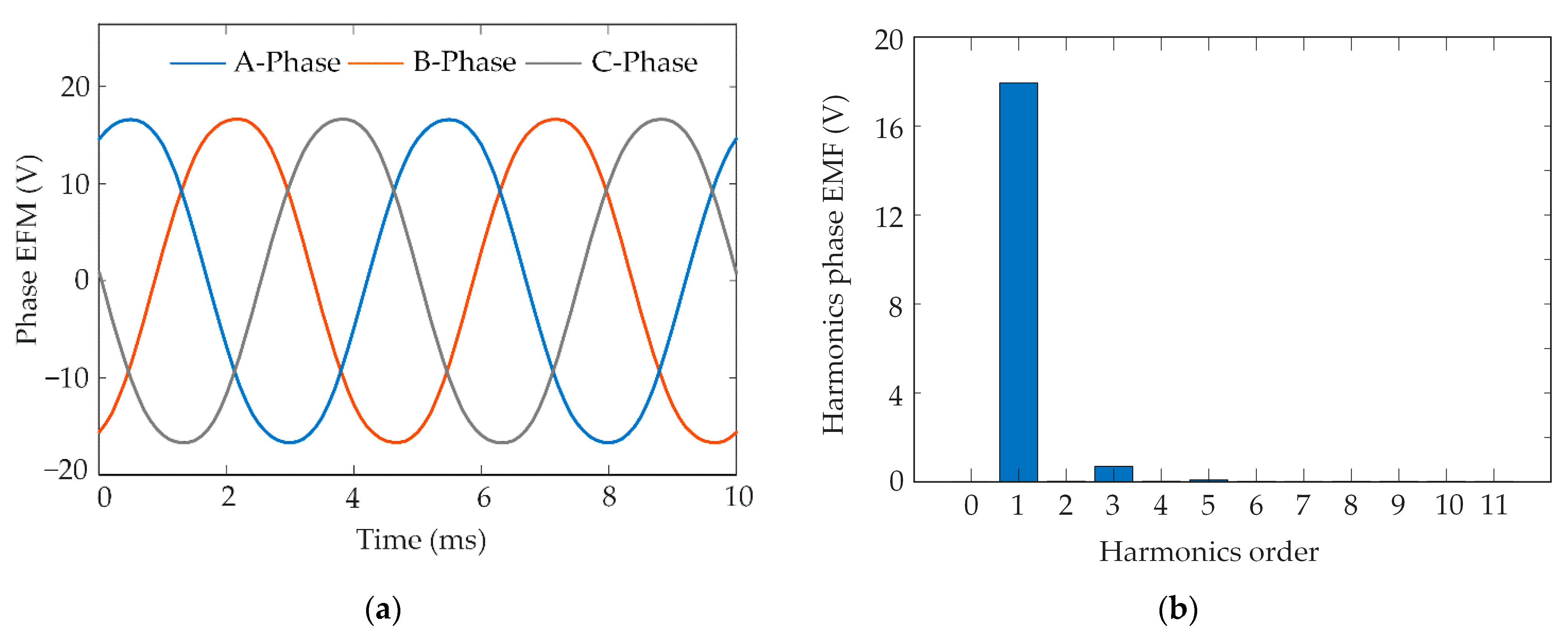
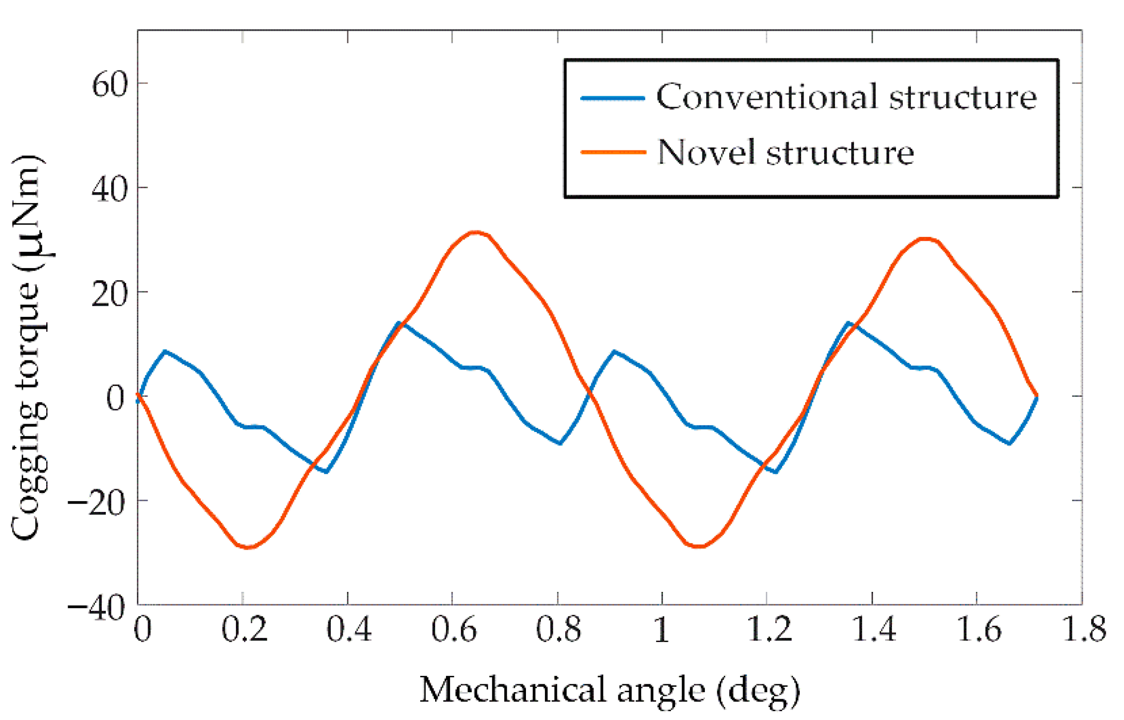
4.2. Electromagnetic Characteristic

With the parameters in Table 2, the model of the BWPMTM was established based on finite element software. According to the simulation results, the no-load air gap flux density, no-load back EMF, temperature and torque were analyzed. Figure 9 presents the magnetic flux density distribution diagram of the BWPMT on no-load. It is easy to see that the magnetic flux lines are closed by the permanent magnet, air gap, stator teeth and shell to form a loop. The maximum magnetic flux density was 1.85 T in the magnetic barrier, as shown in Figure 9b, which is in an oversaturation state. The maximum magnetic flux density of the stator tooth is 1.2 T.
The air gap flux density waveform and the corresponding harmonics of the BWPMTM in the no-load condition are shown in Figure 10. Figure 10a shows the air gap flux density waveform. Figure 10b depicts the spectral analysis of the air gap flux density. The amplitude of the air gap flux density is 0.95 T, and the amplitude of the fundamental component is 1.14 T.
The no-load back EMF waveform and the corresponding harmonics are shown in Figure 11 at a rotation speed of 1200 rpm. The phase back EMF waveform approximates the sinusoidal waveform and is symmetric. Therefore, there are no even harmonics in the back EMF waveform. The third harmonic content is small, and the remaining harmonics are almost zero. The amplitude of no-load phase back EMF is 17.2 V. The amplitude of the fundamental component is 18 V. The back EMF coefficient is defined as:
k = E p p f
where E p p is the peak-to-peak value of back EMF.
It can be inferred from the above equation that the phase back EMF coefficient is 0.172 V/Hz. According to the relationship between line EMF and phase EMF, the line back EMF coefficient is 0.298 V/Hz.
Figure 12 shows the cogging torque waveforms of the conventional PMTM and the BWPMTM. It can be observed that the BWPMTM can effectively reduce the cogging torque compared with the conventional PMTM. The maximum cogging torques of the BWPMTM and the conventional PMTM are 14 μNm and 31 μNm, respectively. The closed slot is an effective measure for weakening the cogging torque. Due to the characteristics of the slots on the outer surface of the stator of the BWPMTM, no slotting of the inner surface of the stator will not result in variation in air-gap reluctance. So, the structure of the BWPMTM can effectively reduce the cogging torque.

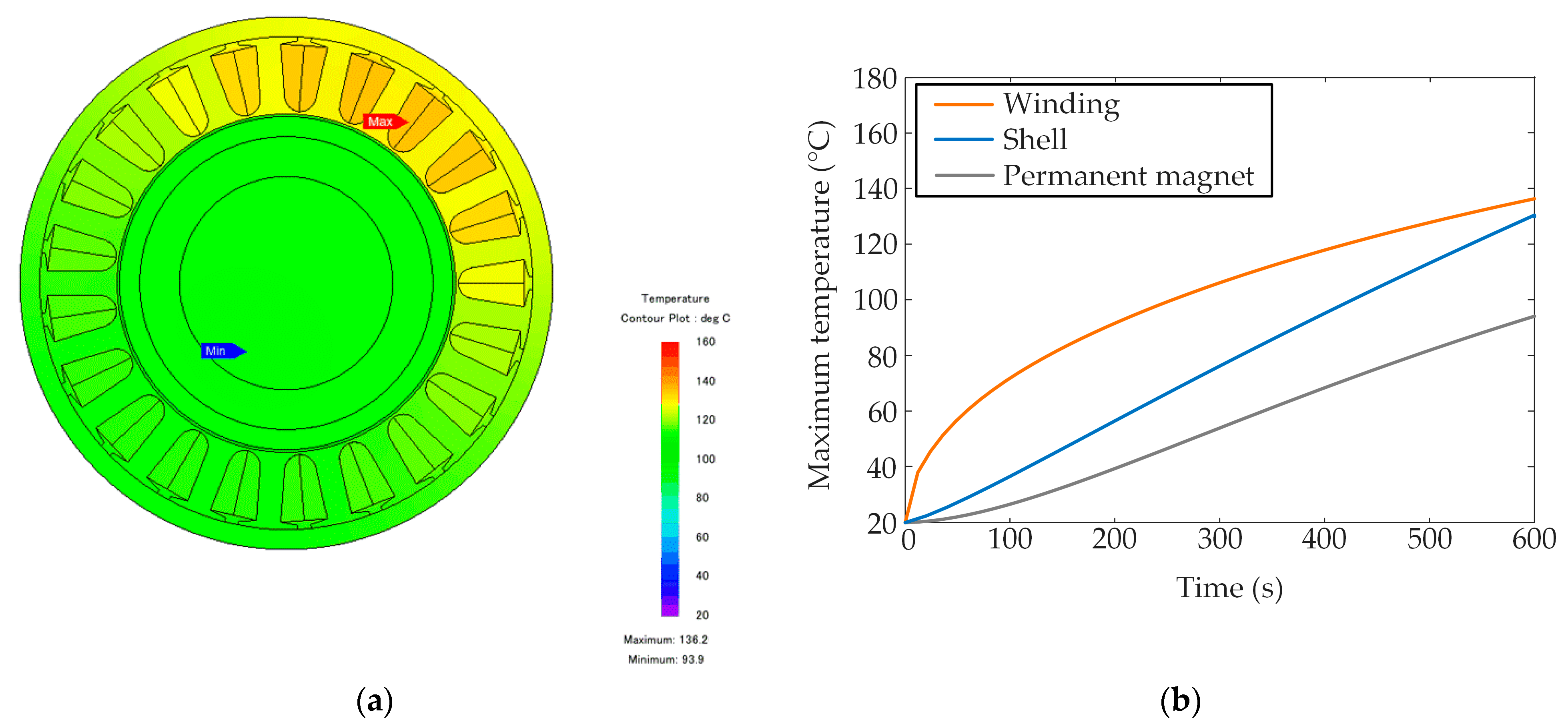
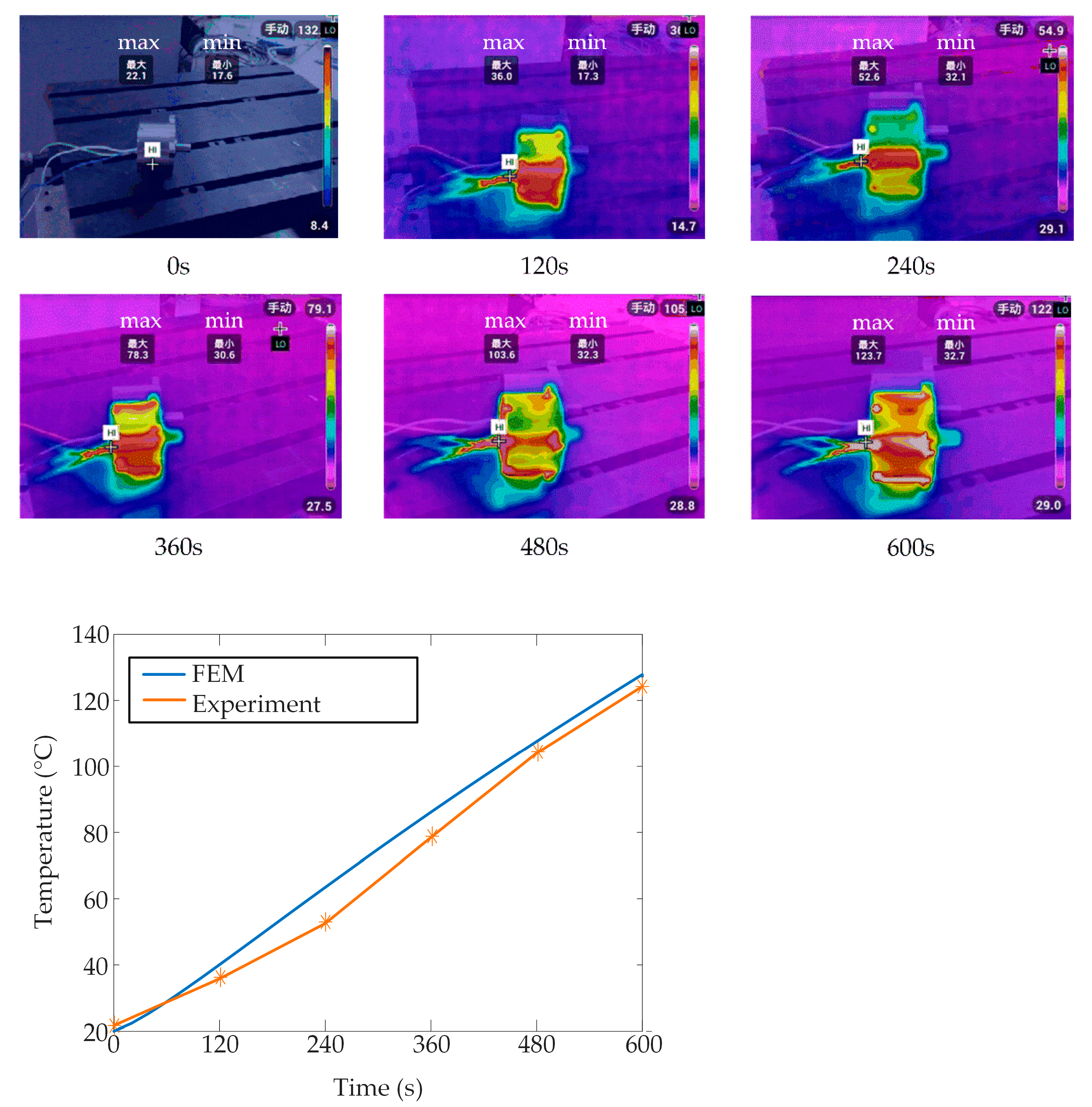
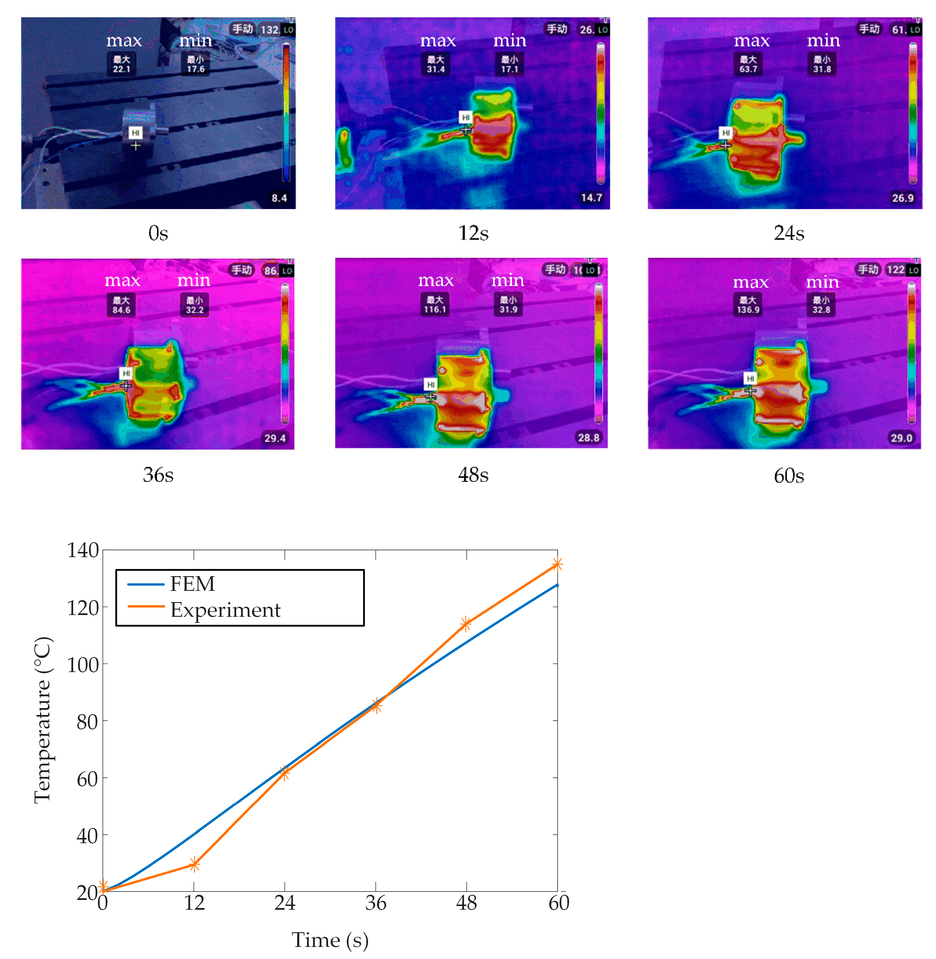
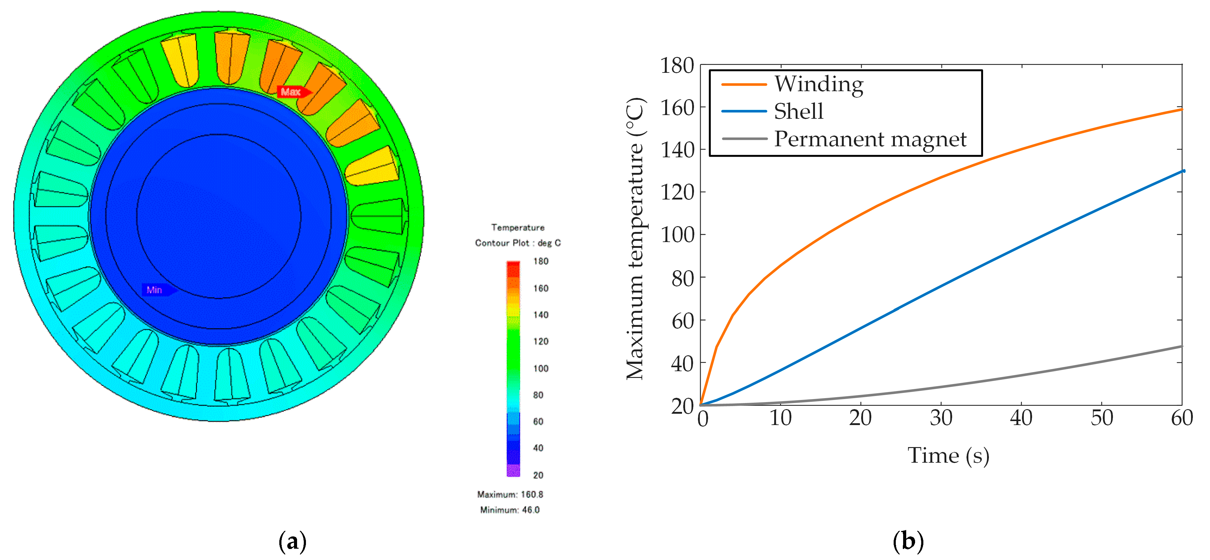
4.3. Temperature Distribution

The core loss is small and can be ignored when the motor works under the locked-rotor condition. Therefore, the winding copper loss is only considered in the temperature field analysis. The model of the BWPMTM was established by three-dimensional finite element temperature field simulation software, with the initial temperature set at 20 °C. The influence of heat radiation on the temperature must be considered when the motor adopts the natural cooling method. As copper loss decreases with the increase in resistance and resistance increases with the increase in temperature, copper loss decreases with the increase in temperature. In this section, the temperature distribution of the motor is analyzed under the two working conditions of the continuous locked-rotor condition for 10 min and the peak locked-rotor condition for 1 min.
Figure 13 shows a diagram of the temperature field and the maximum temperature curves of the winding, shell and permanent magnet when the motor works under the continuous locked-rotor condition for 10 min at the locked-rotor position θ = 0 ° . As the heat source is generated by the winding, the winding temperature rises rapidly at the beginning, and after about 1 min, the increase drops off slightly. With the effect of heat conduction and radiation, the temperature of the shell and permanent magnet increases rapidly with the temperature of the winding. At 10 min, the maximum temperature of the motor is 136.2 °C at the A-phase winding. The maximum temperature of the B-phase winding is equal to that of the C-phase winding and is 127.3 °C. This is consistent with the above theoretical analysis. The maximum temperature of the shell is slightly lower than that of the winding at 130.5 °C, and the maximum temperature of the permanent magnet is 94.8 °C.
Figure 14 shows a diagram of the temperature field and the maximum temperature curves when the motor works under the peak locked-rotor condition for 1 min at the locked-rotor position θ = 0 ° . The temperature distribution of the motor and the maximum temperature curves of the winding and shell are similar to that of the motor under the continuous locked-rotor condition. The temperature difference of each part is greater. At 1 min, the maximum temperature of the motor is 160.8 °C at the A-phase winding. The maximum temperature of the B-phase winding is equal to that of the C-phase winding and is 124.2 °C. The maximum temperature of the shell is 127.9 °C. As the inner surface of the stator and the outer surface of the rotor dissipate and absorb heat through thermal radiation, less heat is transferred to the rotor through the air gap per minute. The temperature of the rotor is lower. The maximum temperature of the permanent magnet is 48.6 °C, which is lower than the maximum temperature of the permanent magnet under the continuous locked-rotor condition for 10 min. It can be seen that the temperature has not reached a steady state under the two locked-rotor conditions, that is, the motor is at the highest temperature for only a short time, which is conducive to its safe operation. Meanwhile, the maximum temperatures under the two conditions all meet the design requirements and retain a certain safety margin.

4.4. Impact of Temperature on Torque

From the simulation results for the temperature field, the temperature of the motor increases rapidly, which increases the winding resistance and decreases the torque. Therefore, the torque calculation considering temperature is necessary. It can be seen from Figure 13 and Figure 14 that the temperature difference between the different slots is large, but the temperature difference in a slot is small. To simplify the calculation, it is reasonable to take the average temperature in the slot as the winding temperature. Figure 15 shows the torque curves considering temperature corresponding to the conditions of the continuous locked-rotor condition for 10 min and the peak locked-rotor condition for 1 min. As the motor has the highest temperature and the largest resistance at the last moment, the locked-rotor torque is the smallest. At the last moment, the continuous locked-rotor torque is 0.3 Nm. The peak locked-rotor torque is 0.6 Nm. The torques meet the design specifications under the two working conditions. The continuous locked-rotor torque density is 2 Nm/kg, wherein the weight is 0.151 kg. The torque density is increased by 30% compared with the maxon motor of specification 758031 with torque density of 1.54 Nm/kg, wherein continuous locked-rotor torque is 0.416 Nm and its weight is 0.27 kg.

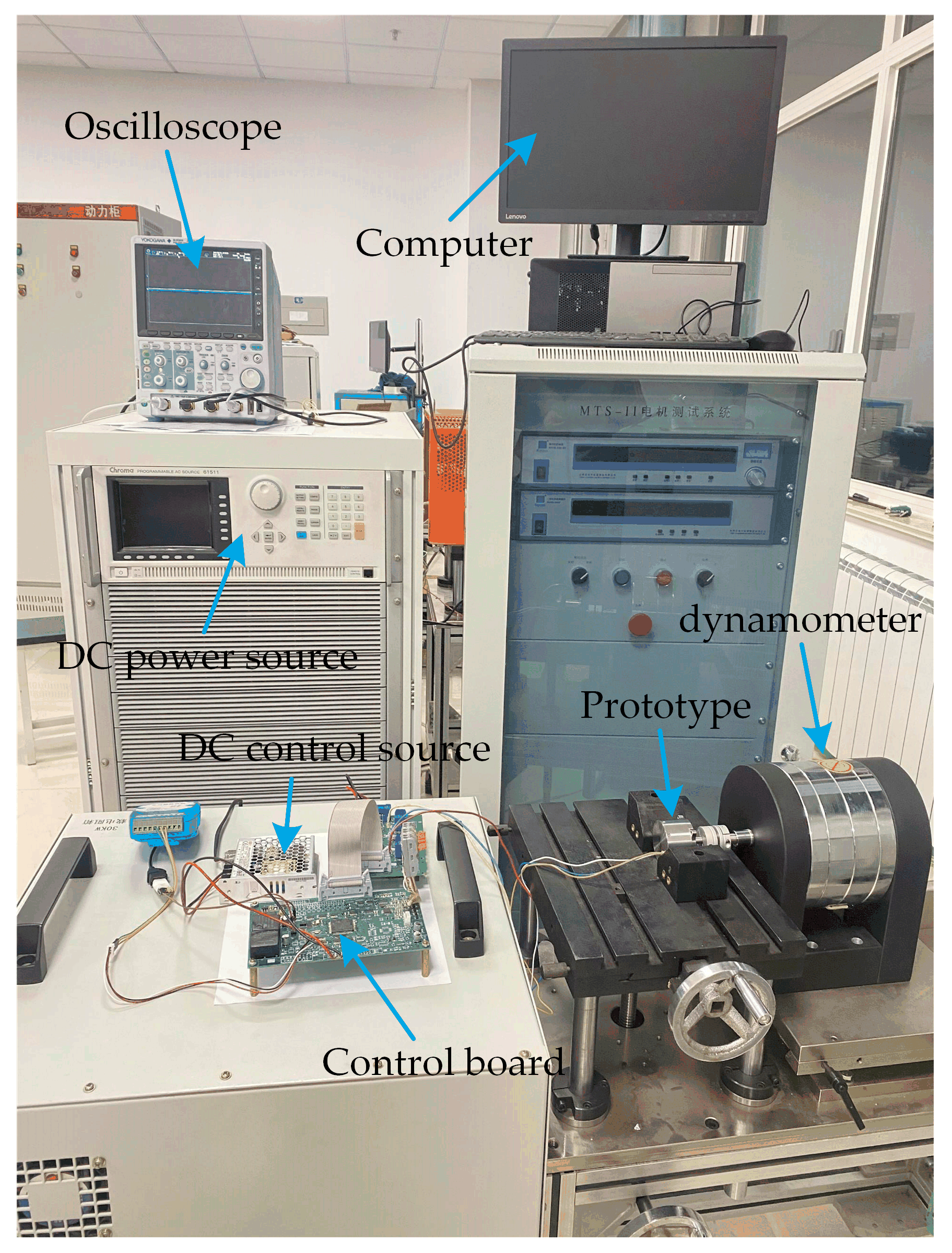
5. Prototype Motor and Experiments

The manufacture of the prototype and the experimental results for the proposed BEPMTM are presented in this section. The designed motor and the experiment bench are presented in Figure 16. In order to verify the performance of the BWPMTM, no-load and lock-load experiments were carried out. All the performances of the BWPMTM prototype were verified successfully.

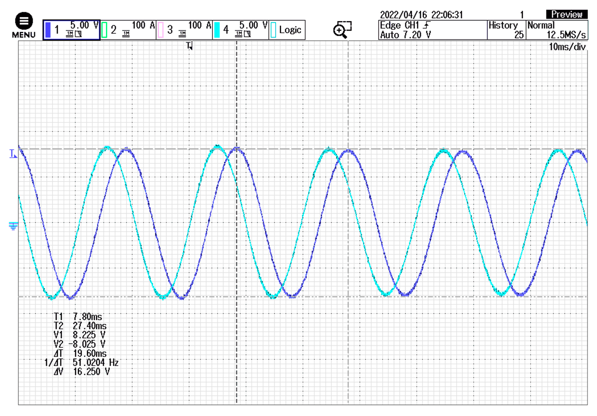
5.1. No-Load Experiment

Figure 17 shows the back EMF measurement of the BWPMTM under the no-load condition. The experimental line back EMF coefficient was 0.318 V/Hz. By comparing this with the simulated line back EMF coefficient of 0.298 V/Hz, it was found that the experimental result fits well with the FEM result. A small difference was observed due to the accuracy of the experimental system. The FEM result is slightly lower than the experimental ones, with a maximum error of 6.3%, showing the general agreement between the FEM and experiment.

5.2. Temperature Experiment

The temperature of the prototype under the two experimental locked-rotor conditions was measured using a noncontact infrared thermometer. The measured temperature curves versus time are shown in Figure 18 and Figure 19, respectively. The initial temperature was 22.1 °C. As shown, the experimental temperature distribution of the BWPMTM model shows great agreement with the FEM. The maximum temperature of the shell was 123.7 °C under the continuous locked-rotor condition after 1 min. The maximum error rate between the experiment and the FEM was less than 6%. The maximum temperature was 136.9 °C under the peak locked-rotor condition after 10 min. The maximum error rate between the experiment and the FEM was less than 7%. From an engineering perspective, these errors are acceptable.

6. Discussion

In the BWPMTM proposed in this paper, the outer surface of the stator is slotted. From the point of view of processing technics, the winding coils are embedded in the slots from the outer diameter of the stator, which makes processing more convenient and simpler. From the point of view of performance, the novel structure does not have the stator yoke and the size of the motor can be made smaller, which could increase motor power. Moreover, due to the simpler process, the slot space factor can be improved to a certain extent, making the motor performance superior. This paper proposes a limit analytical method, which takes minimum stack length as the objective function to determine the optimal parameters of the motor, considering four constraints of no-load back EMF, torque, temperature and slot space factor. In this design method, the optimal parameters of the motor are solved directly by known constraints, avoiding the calculation of large-scale searches through scanning and iteration. With this design method, the temperature and the slot space factor have reached the limit. This indicates that the motor parameters have been minimized and that motor materials have been fully used.
The electromagnetic performance was investigated with finite element electromagnetic simulation. Finally, experimental tests on the BWPMTM prototype were undertaken. The experimental results were in good agreement with the results of the FEM, which successfully verified the performance of the motor.
The FEM and experimental results verified the feasibility of the proposed structure and the rationality of the design scheme. The proposed limit analytical method can also serve as a reference for the design of other types of motor.

Author Contributions

Conceptualization, B.Z.; investigation, Y.C. and P.Y.; writing—original draft preparation, S.G.; software, S.G.; writing—review and editing, B.L.; supervision, C.Z. All authors have read and agreed to the published version of the manuscript.

Funding

This research was funded by the National Natural Science Foundation of China (52075307) and the Natural Science Foundation of Shandong Province (ZR2020QE217).

Conflicts of Interest

The authors declare no conflict of interest.

References

  1. Onsal, M.; Cumhur, B.; Demir, Y.; Yolacan, E. Rotor design optimization of a new flux-assisted consequent pole spoke-type permanent magnet torque motor for low-speed applications. IEEE Trans. Magn. 2018, 54, 8206005. [Google Scholar] [CrossRef]
  2. Jo, I.H.; Lee, J.; Lee, H.W.; Lee, J.B.; Lim, J.H.; Kim, S.H.; Park, C.B. A Study on MG-PMSM for High Torque Density of 45 kW–Class Tram Driving System. Energies 2022, 15, 1749. [Google Scholar] [CrossRef]
  3. Gao, C.; Gao, M.; Si, J.; Hu, Y.; Gan, C. A novel direct-drive permanent magnet synchronous motor with toroidal windings. Energies 2019, 12, 432. [Google Scholar] [CrossRef] [Green Version]
  4. Zhang, Z.; Yu, S.; Zhang, F.; Jin, S.; Wang, X. Electromagnetic and Structural Design of a Novel Low-Speed High-Torque Motor with Dual-Stator and PM-Reluctance Rotor. IEEE Trans. Appl. Supercon. 2020, 30, 5203605. [Google Scholar] [CrossRef]
  5. Bacco, G.; Bianchi, N.; Luise, F. High-torque low-speed permanent magnet assisted synchronous reluctance motor design. In Proceedings of the 2019 IEEE International Electric Machines and Drives Conference (IEMDC), San Diego, CA, USA, 12–15 May 2019; pp. 644–649. [Google Scholar]
  6. Wu, S.; Zhao, X.; Jiao, Z.; Luk, P.C.-K.; Jiu, C. Multi-objective optimal design of a toroidally wound radial-flux Halbach permanent magnet array limited angle torque motor. IEEE Trans. Ind. Electron. 2016, 64, 2962–2971. [Google Scholar] [CrossRef] [Green Version]
  7. Chai, W.; Lipo, T.A.; Kwon, B.I. Design and optimization of a novel wound field synchronous machine for torque performance enhancement. Energies 2018, 11, 2111. [Google Scholar] [CrossRef] [Green Version]
  8. Chu, W.Q.; Zhu, Z.Q. Reduction of on-load torque ripples in permanent magnet synchronous machines by improved skewing. IEEE Trans. Magn. 2013, 49, 3822–3825. [Google Scholar] [CrossRef]
  9. Zhao, W.; Lipo, T.A.; Kwon, B.I. Torque pulsation minimization in spoke-type interior permanent magnet motors with skewing and sinusoidal permanent magnet configurations. IEEE Trans. Magn. 2015, 51, 8110804. [Google Scholar] [CrossRef]
  10. Zhu, Z.Q.; Howe, D. Influence of design parameters on cogging torque in permanent magnet machines. IEEE Trans. Energy Convers. 2000, 15, 407–412. [Google Scholar] [CrossRef] [Green Version]
  11. Demir, Y.; Aydin, M. A novel dual three-phase permanent magnet synchronous motor with asymmetric stator winding. IEEE Trans. Magn. 2016, 52, 8105005. [Google Scholar] [CrossRef]
  12. Chen, N.; Ho, S.L.; Fu, W.N. Optimization of permanent magnet surface shapes of electric motors for minimization of cogging torque using FEM. IEEE Trans. Magn. 2010, 46, 2478–2481. [Google Scholar] [CrossRef]
  13. Vicente, S.-S.; Auxiliadora, S.-G.; Manuel, B.-P.; José-Ramón, C.-B. Optimisation of Magnet Shape for Cogging Torque Reduction in Axial-Flux Permanent-Magnet Motors. IEEE Trans. Energy Convers. 2021, 36, 2825–2838. [Google Scholar]
  14. Yu, H.; Yu, G.; Xu, Y.; Zou, J. Torque performance improvement for slotted limited-angle torque motors by combined SMA application and GA optimization. IEEE Trans. Magn. 2020, 57, 8200305. [Google Scholar] [CrossRef]
  15. Zhang, J.; Zhang, B.; Feng, G.; Gan, B. Design and Analysis of a Low-Speed and High-Torque Dual-Stator Permanent Magnet Motor With Inner Enhanced Torque. IEEE Access 2020, 8, 182984–182995. [Google Scholar] [CrossRef]
  16. Ma, P.; Wang, Q.; Li, Y.; Jiang, S.; Zhao, M. Research on Torque Ripple Suppression of the Slotted Limited Angle Torque Motor. IEEE Trans. Magn. 2020, 57, 8200106. [Google Scholar] [CrossRef]
  17. Zou, J.B.; Yu, G.D.; Xu, Y.X.; Li, J.L.; Wang, Q. Design and analysis of a permanent magnet slotted limited-angle torque motor with special tooth-tip structure for torque performance improvement. In Proceedings of the 2015 IEEE International Conference on Applied Superconductivity and Electromagnetic Devices (ASEMD), Shanghai, China, 20–23 November 2015; pp. 246–247. [Google Scholar]
  18. Kim, M.; Cho, S.; Lee, K.; Lee, J.; Han, J.; Jeong, T.; Kim, W.; Koo, D.; Lee, J. Torque density elevation in concentrated winding interior PM synchronous motor with minimized magnet volume. IEEE Trans. Magn. 2013, 49, 3334–3337. [Google Scholar] [CrossRef]
  19. Chai, J.; Zhao, T.; Gui, X. Multi-Objective Optimization Design of Permanent Magnet Torque Motor. World Electr. Veh. J. 2021, 12, 131. [Google Scholar] [CrossRef]
  20. Chung, S.U.; Kim, J.W.; Chun, Y.D.; Woo, B.C.; Hong, D.K. Fractional slot concentrated winding PMSM with consequent pole rotor for a low-speed direct drive: Reduction of rare earth permanent magnet. IEEE Trans. Energy Convers. 2015, 30, 103–109. [Google Scholar] [CrossRef]
  21. Li, Y.; Zhu, Z.Q.; Li, G.J. Influence of stator topologies on average torque and torque ripple of fractional-slot SPM machines with fully closed slots. IEEE Trans. Ind. Appl. 2018, 54, 2151–2164. [Google Scholar] [CrossRef]
  22. Hu, Y.; Zhu, S.; Xu, L.; Jiang, B. Reduction of Torque Ripple and Rotor Eddy Current Losses by Closed Slots Design in a High-speed PMSM for EHA Applications. IEEE Trans. Magn. 2022, 58, 8102206. [Google Scholar] [CrossRef]
  23. Chen, H.; Qu, R.; Li, J.; Li, D. Demagnetization performance of a 7 MW interior permanent magnet wind generator with fractional-slot concentrated windings. IEEE Trans. Magn. 2015, 51, 2442263. [Google Scholar] [CrossRef]
  24. De Donato, G.; Capponi, F.G.; Rivellini, G.A.; Caricchi, F. Integral-slot versus fractional-slot concentrated-winding axial-flux permanent-magnet machines: Comparative design, FEA, and experimental tests. IEEE Trans. Ind. Appl. 2012, 48, 1487–1495. [Google Scholar] [CrossRef]
  25. Jia, G.X.; Zhao, H.C.; Shao, H.J. Simulation research on PMSM vector control system based on SVPWM. In Proceedings of the 2010 International Conference on Electrical and Control Engineering, Wuhan, China, 25–27 June 2010; pp. 1936–1940. [Google Scholar]
Figure 1. Cross-sectional view: (a) the conventional PMTM; (b) the novel BWPMTM; (c) the local structure.
Energies 15 04662 g001
Figure 2. Spatial distribution diagram of the three−phase winding motor.
Energies 15 04662 g002
Figure 3. Design flow chart: (a) the traditional analytical method; (b) the proposed limit analytical method.
Energies 15 04662 g003
Figure 4. The control circuit of the motor.
Energies 15 04662 g004
Figure 5. Copper loss curves of the three-phase winding motor.
Energies 15 04662 g005
Figure 6. Circuit diagram at maximum A-phase current.
Energies 15 04662 g006
Figure 7. (a) Solutions of Equation (20). (b) Solutions of Equation (21).
Energies 15 04662 g007
Figure 8. Result of mesh generation.
Energies 15 04662 g008
Figure 9. The magnetic flux density distributions on no-load: (a) the motor; (b) the magnetic barrier.
Energies 15 04662 g009
Figure 10. (a) Air gap flux density waveform. (b) Harmonics of air gap flux density.
Energies 15 04662 g010
Figure 11. (a) The phase back EMF under the no-load condition. (b) Harmonics of phase back EMF.
Energies 15 04662 g011
Figure 12. The cogging torque waveforms for two different configurations.
Energies 15 04662 g012
Figure 13. Temperature under the continuous locked-rotor condition for 10 min: (a) diagram of the temperature field; (b) maximum temperature curves of winding, shell and permanent magnet.
Energies 15 04662 g013
Figure 14. The temperature under the peak locked-rotor condition for 1 min: (a) diagram of the temperature field; (b) maximum temperature curves of winding, shell and permanent magnet.
Energies 15 04662 g014
Figure 15. The torque curves: (a) continuous locked-rotor condition for 10 min; (b) peak locked-rotor condition for 1 min considering temperature.
Energies 15 04662 g015
Figure 16. Prototype and experiment platform of the BWPMTM prototype.
Energies 15 04662 g016
Figure 17. No-load back EMF.
Energies 15 04662 g017
Figure 18. Temperature for the experiment under the continuous locked-rotor condition and the maximum temperature curve of the shell.
Energies 15 04662 g018
Figure 19. The temperature experiment under the peak locked-rotor condition and the maximum temperature curve of the shell.
Energies 15 04662 g019
Table 1. The specifications of the BWPMTM.
ParameterValue
Maximum stack length 25 mm
Shell outer diameter 40 mm
Number of pole pairs10
Number of slots21
Maximum no-load speed1200 rpm
Continuous locked-rotor voltage14 V
Peak locked-rotor voltage28 V
Continuous locked-rotor torque0.3 Nm
Peak locked-rotor torque0.6 Nm
Slot space factor0.3
Maximum working temperature 180 °C
Initial temperature 20 °C
Table 2. Main parameters of the BWPMTM.
ParametersValueUnit
Stack length 18mm
Shell outer diameter40mm
Stator outer diameter37mm
Stator inner diameter24.6mm
Rotor outer diameter22mm
Permanent magnet thickness2mm
Air gap length0.2mm
Magnetic barrier thickness0.2mm
Section area of single wire0.056mm2
Number of series turns per phase322-
Phase resistance4.8 Ω
Continuous locked-rotor current2 A
Peak locked-rotor current4 A
Table 3. The material properties.
Permanent MagnetSilicon Steel SheetSteel C101
Density/kg·m−37400Density/kg·m−37650Density/kg·m−37900
Remanence/T1.05Thickness/mm0.5Resistivity/Ωm 6.098 × 10⁻⁷
Coercive force/kA·m−1764Saturation flux
density/T
2.2Saturation flux
density/T
1.8
Publisher’s Note: MDPI stays neutral with regard to jurisdictional claims in published maps and institutional affiliations.

