Article

Advanced Couplings and Multiphysics Sensitivity Analysis Supporting the Operation and the Design of Existing and Innovative Reactors

Framatome, 1 Place Jean Millier, 92084 Paris La Défense, France
*
Author to whom correspondence should be addressed.
Energies 2022, 15(9), 3341; https://doi.org/10.3390/en15093341
Submission received: 31 March 2022 / Revised: 21 April 2022 / Accepted: 26 April 2022 / Published: 4 May 2022
(This article belongs to the Special Issue Advanced Numerical Modelling Techniques for Nuclear Reactors)

Abstract

:
Codes and methods are subjected to a continuous update process for answering the regulatory requirements concerning the long-term operation of existing reactors and new concept deployment. In this continuous improvement process, new generation codes are developed for supporting industrial applications and the long-term strategy. In this paper, attention is devoted to selecting codes under development in France for lattice and core steady-state and transient calculations. These codes, APOLLO3® and CATHARE3, have been selected for carrying out the activities of the H2020 CAMIVVER Project oriented to the 3D-multiphysics couplings improvements. Multiscale and multiphysics solutions are key topics to keep competitiveness and answer to newer industrial needs in plant operations, licensing, and safe operating envelope requirements. The paper presents an overview of the activities performed by Framatome to support the definition of benchmarks exercises proposed in the CAMIVVER Project. Small core configurations subjected to a Reactivity Insertion Accident (RIA) are presented with associated preliminary results. To open the discussions toward the development of Best-Estimate Plus Uncertainties (BEPU) solutions, the URANIE statistical platform was used for sensitivity analysis over different configurations. These preliminary results are also presented.

1. Introduction

In the framework of the H2020 CAMIVVER Project (Codes and Methods Improvements for VVER comprehensive safety assessment) [1,2], one of the objectives identified is the development of a new generation of innovative codes and methods. The aim is to improve the comprehension of the physical phenomena occurring in the core under steady-state and transient conditions to be applied to different reactor types.
Codes and methods are subjected to a continuous update to answer the regulatory requirements for existing reactors’ long-term operation (LTO) and new concept deployment. For supporting the industrial applications and the long-term strategy, new generation codes, namely APOLLO3® [3] and CATHARE3 [4] developed in France by CEA, have been selected for carrying out activities within the H2020 CAMIVVER Project [2]. These codes provide an improvement of the treated physics in comparison to previous generation codes, providing the users easy access to several modeling capabilities (diffusion vs. transport resolutions, 3D vs. 1D CATHARE3 core thermal-hydraulic representation, 2D and 3D lattice capabilities in APOLLO3, etc.) to deeply analyze the physical behavior of the nuclear supply system. They allow for more robust use of 3D solutions for treating complex core phenomena. The new generation of French codes is based on modern programming languages (e.g., Python interfaces), and the users may profit from parallel solutions. However, these codes (in particular, APOLLO3®) are under development at the laboratory level, and the industrialization process is ongoing for daily industrial applications.
Multiscale and multiphysics solutions are key topics to maintain competitiveness and address newer industrial needs in plant operations, licensing, and safe operating envelope definition. The development of innovative solutions, such as the High-Fidelity Best-Estimate Plus Uncertainties (BEPU) approach, will help to increase the robustness of traditional multiphysics couplings supporting bias analysis and reduction.
In the framework of the CAMIVVER Project, efforts are dedicated to making a step forward by integrating the industrial view (and its needs) into the ongoing discussion at the international level [5,6,7,8,9,10,11] on multiphysics approaches. The project partners are working together to benchmark deterministic and stochastic codes, as well as different 3D-multiphysics couplings. For this purpose, core cases and transients have been chosen to emphasize the apport of the different solutions, particularly Best Estimate 3D neutronics/thermal-hydraulics-coupled solutions.
Whichever multiphysics solution is adopted, Verification and Validation (V&V) is a major activity required by safety authorities. The V&V approach is represented schematically in Figure 1, where single physics are at the bottom and multiphysics are at the top. The V&V approach may be decomposed into different phases, and it requires the integration of several competencies, starting from nuclear data and neutronics up to coupled thermal-hydraulic modelling, and finalized to the comprehension of core/system behavior under normal and accidental conditions. In this framework, benchmarks, statistical libraries, and sensitivity analysis techniques become more important for consolidating the full system response prediction, in agreement with the latest French Safety Authorities Guides [12].
For supporting benchmark exercises between 3D neutronics/thermal-hydraulics co-pled calculations and simplified modeling, small-size core models (described in Section 2.1) have been proposed in the H2020 CAMIVVER Project. These reduced-size configurations allow computational time to be reasonable, either for the deterministic solutions or the stochastics ones [5].
The robustness of the codes currently developed and used for the western Pressurized Water Reactor (PWR) configurations will also be tested for hexagonal geometry and triangular lattice configurations typical of other reactor types under operation or conception as VVER (Vodo-Vodyanoi Enyergeticheskiy reactor) and Fast Reactors (FR) types. In accordance with the Strategic Research and Innovation Agenda from SNE-TP [13], the CAMIVVER Project promotes the use of multidisciplinary deterministic methodologies to describe the interaction between thermal hydraulics and neutronics by a proof of concept of APOLLO3®/CATHARE3 coupling that will be compared to other solutions, e.g., stochastic coupled solutions [2,5] for different reactors types.
In this paper, the test cases proposed in the CAMIVVER Project are described (Section 2.1) as well as the codes and methods adopted by Framatome (Section 2.2).
The Framatome contribution presented here is mainly characterized by the use of different multiphysics solutions based on deterministic calculations. The deterministic approach remains the most widespread at the industrial level due to its performance [14], even though more accurate and CPU time-consuming calculations; for instance, the Monte Carlo coupled to computational fluid dynamic (CFD) codes, are foreseen for the process of codes validations.
The deterministic approach is based on the “two-step” scheme and on the fundamental mode hypothesis approximations (2D calculations at assembly level—lattice calculation). Under this scheme, it is necessary to prepare in advance multiparametric data libraries (cross-sections library isotope and conditions dependent evaluated over 2D small geometries, i.e., assembly-size) for the core steady-state and transient calculations. In this paper, the activities carried out within the CAMIVVER Project on lattice calculations are not detailed. However, to investigate the interactions between phenomena impacting the cross-sections preparation, a step-by-step approach is proposed based on the URANIE, Uncertainty and Sensitivity platform developed by the CEA [15]. URANIE is used as a statistical library applied to APOLLO3 2D and 3D calculations before analyzing the core behavior under steady-state and transient conditions.
This step-by-step approach has been set up to support the benchmark exercises proposed in the CAMIVVER Project for facilitating the investigation of discrepancies among codes and identifying in advance the dominant effects. The analyses performed using the URANIE statistical library are shown in Section 3.2.
Several transients have been considered for testing 3D-multiphysics-coupled solutions. In this paper, only a Reactivity Insertion Accident (RIA) has been presented to show the preliminary results obtained and the future perspectives of the CAMIVVER exercises.

2. Materials and Methods

In the following parts of the paper, the configurations and the codes are used described.
The lattice and core configurations (steady-state and transients) for squared (e.g., western PWR) and hexagonal geometries (e.g., VVER) are described in Section 2.1.
The codes used by Framatome in the CAMIVVER Project are described in Section 2.2. In order to support benchmark exercises, Framatome has decided to present a preliminary benchmark with a newly developed coupling (called ATHENA) between 3D core neutronics and thermal-hydraulics [16]. The support of the URANIE [15] statistical library is proposed as well, and these codes and methods are described in Section 2.2.

2.1. Lattice and Core Test Cases Description

Simplified core models have been defined within the CAMIVVER Project (Ref. [1]) for investigating the advantages of 3D neutronics/thermal-hydraulics-coupled calculations while keeping the computational time reasonable.
The size was chosen for favorizing the deployment of an advanced coupling based on APOLLO3®/CATHARE3 (proof of concept under development during the CAMIVVER Project) and the comparison with High-Fidelity Monte Carlo-based solutions coupled with subchannel codes [5]. The choice of reduced size cases has also been made to open the discussion on code capabilities for treating different core sizes and innovative small size reactors as the Small Modular Reactor (SMR) concepts as indicated in other Projects [17].
32 Fuel Assembly PWR Minicore Case
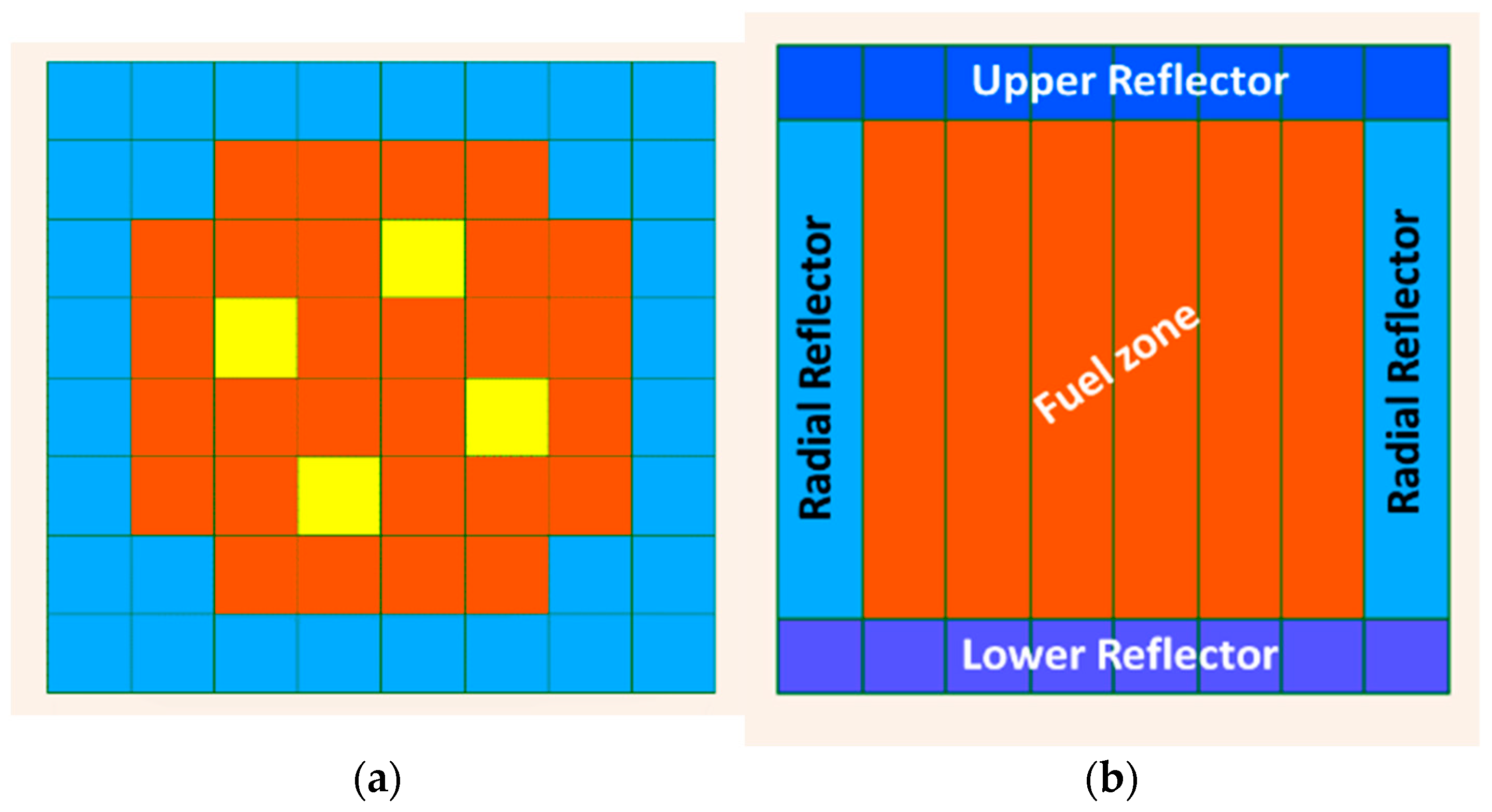
The first configuration analyzed is a 32 Fuel Assemblies (FA) PWR minicore case as described in Figure 2. The configuration, based initially on Ref. [18], has been improved in the framework of the CAMIVVER Project for allowing benchmarks among different codes [19,20].
Figure 2 for a total of thirty-two FAs. The core dimensions are shown in Table 1. In order to simulate several transient scenarios, four control rods (CRs) are located in the central part of the core (see Figure 2). FAs and CRs details are indicated in Table 2 and 
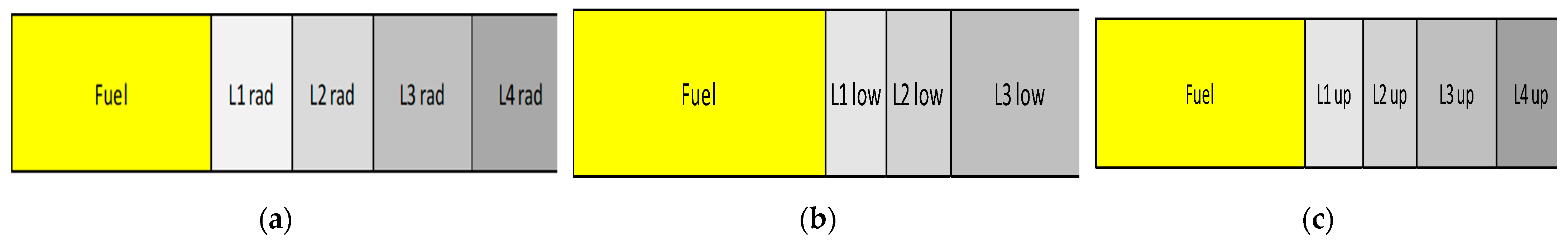
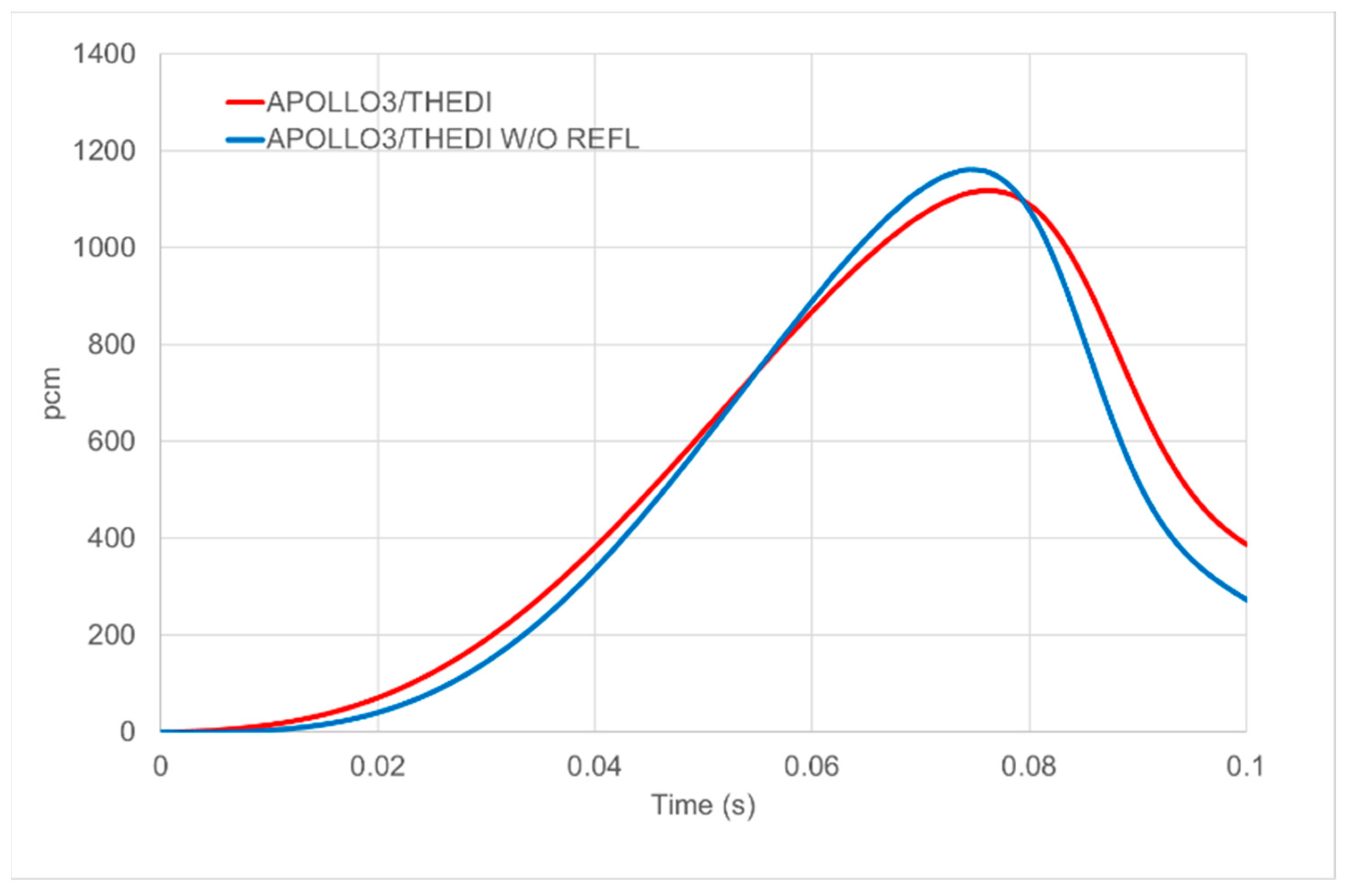
Table 3. The configuration is completed by simplified radial and axial reflector models. The reflectors are modeled as 1D-slab (indicated in Figure 3 as “Li rad” for the radial reflector, “Li low” for the lower reflector, and “Li up” for the upper reflectors), and the composition of each slab is shown in Table 4. More details are available in Refs. [19,20].
Hexagonal Minicore Cases
Hexagonal geometry small core benchmarks typical of VVER type reactor have been proposed within the CAMIVVER Project [19]. The benchmark selected by the project is a small heterogeneous core containing seven hexagonal FA of different types based on the Khmelnytsky-2 or on the Kozloduy-6 specifications [19,20,21,22,23].
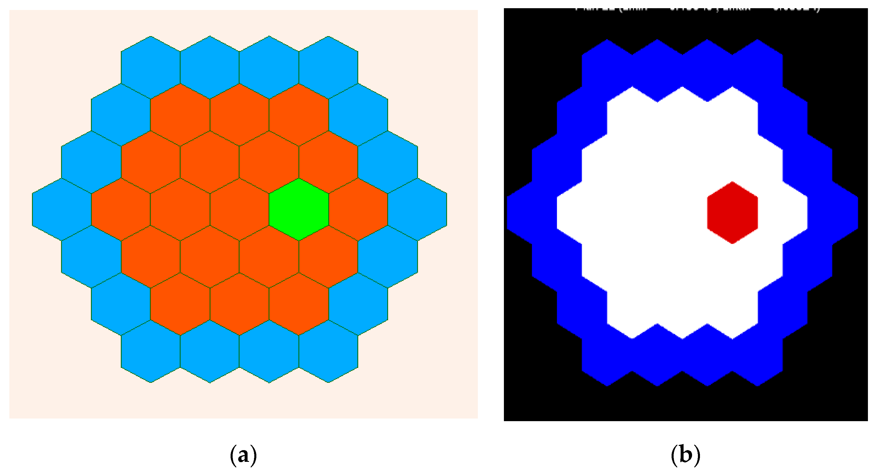
In the present paper, a slightly different configuration has been chosen to test the capability of the sensitivity analysis tool for treating hexagonal geometry (see Figure 4).
The core used is a 19 hexagonal FA core case with a homogeneous fuel loading, as indicated in Figure 4. Three CRs are in the central part of the core (see Figure 4). The configuration is completed by simplified radial and axial reflectors in agreement with the 32 FA PWR minicore case.
This first investigation has been proposed by Framatome to get confident with hexagonal geometry configurations and to test selected code capabilities on hexagonal cases. These preliminary tests support the analyses foreseen during the benchmark exercise planned in the CAMIVVER project [19].
Transients Cases
In the CAMIVVER project, different reactivity insertion accident (RIA) transients have been defined for the core cases selected: (1) a rod ejection event and (2) a sudden change of the thermal-hydraulics boundary conditions [19].
Those transients have been chosen for their interest in challenging innovative 3D-multiphysics solutions.
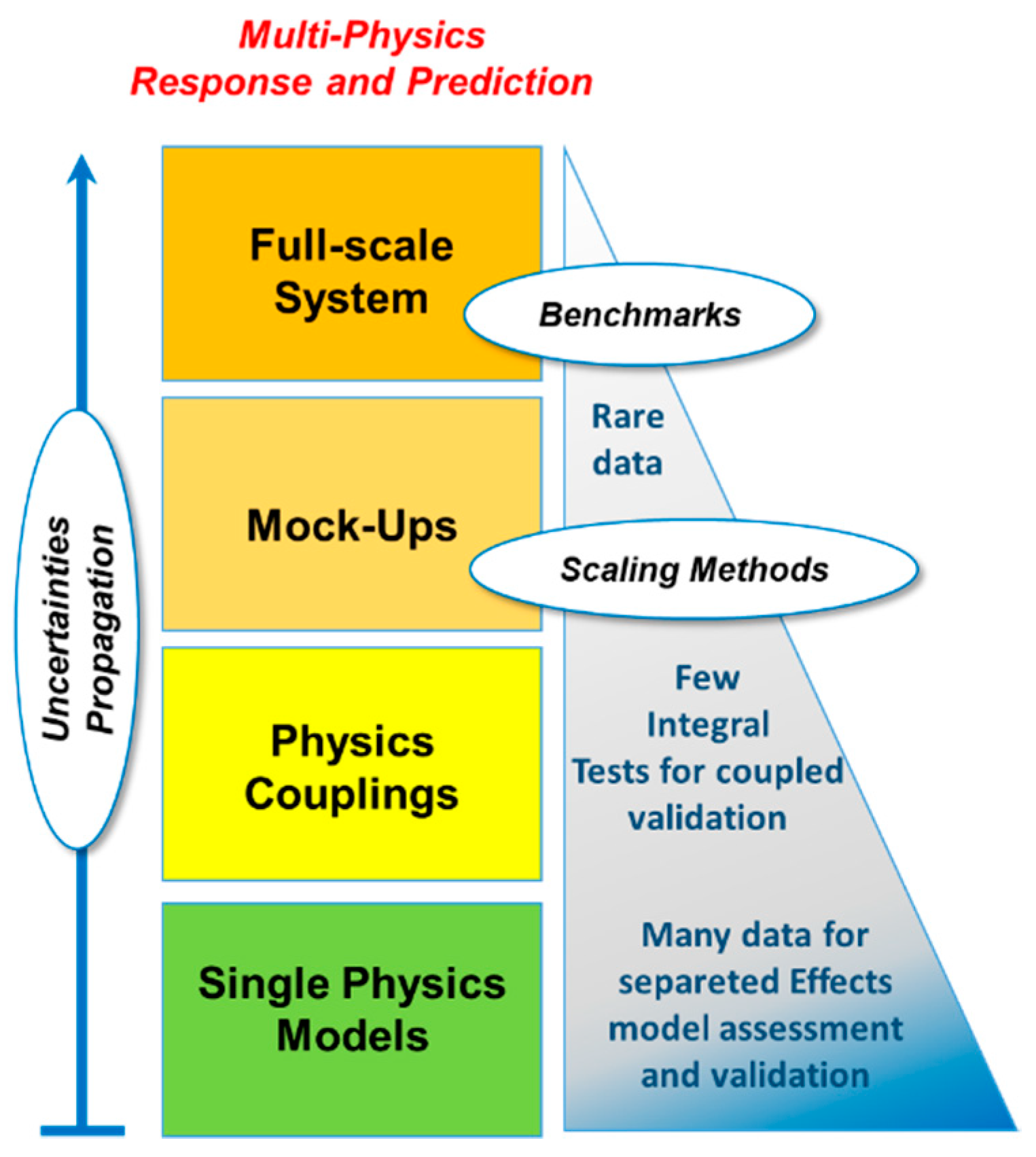
These transients, characterized by different system time-response and feedbacks, are suitable cases to show the relationships among the three types of physics involved in the normal and transient operation of a nuclear power plant: neutronics, thermal-hydraulics, and thermo-mechanics. The fine mesh deeply coupled resolution of the three physics remains up to now, not possible for industrial applications (calculation time and memory imprinting are too important, etc.), and decoupled approaches have been developed in order to speed up calculations and to associate reasonable acceptance to calculated design limits. The decoupling strategy has introduced simplifications to treating those physics depending on the transients and the reactor considered. A more integrated approach (new algorithms for coupling) is currently under investigation, thanks to improved calculation infrastructures (high-performance clusters and parallel algorithms), as indicated in Refs. [6,21]. The interest in developing benchmark exercises between different deterministic approaches and the High-Fidelity Monte Carlo-based approach has significant importance for the industrial V&V strategy (see Figure 1) and to support the robustness of existing approaches (see Ref. [12]).
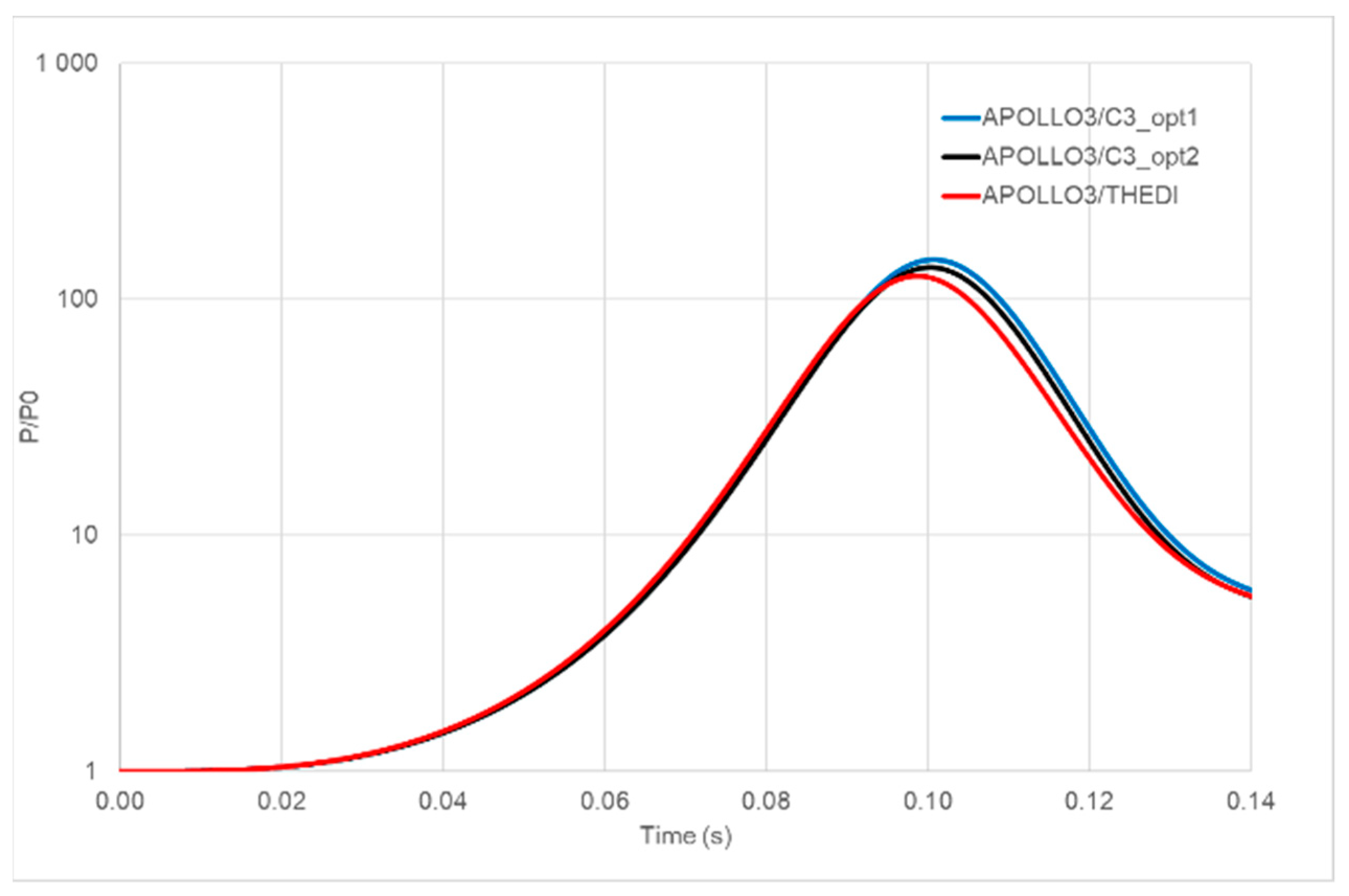
The present paper focuses on the RIA transient where a control rod is ejected in 0.1 s. The ejection of the rod brings an increase in the system reactivity and power with the rapid increase of the fuel temperature. The reactivity insertion is mitigated by the feedback (mainly the Doppler effect) and is followed by a power excursion that depends on the initial core conditions (axial offset, Xe content, boron and temperatures distributions, etc.) and on the type of transient, namely if the reactivity inserted (rho) is lower or higher the effective delayed neutron fraction (βeff).
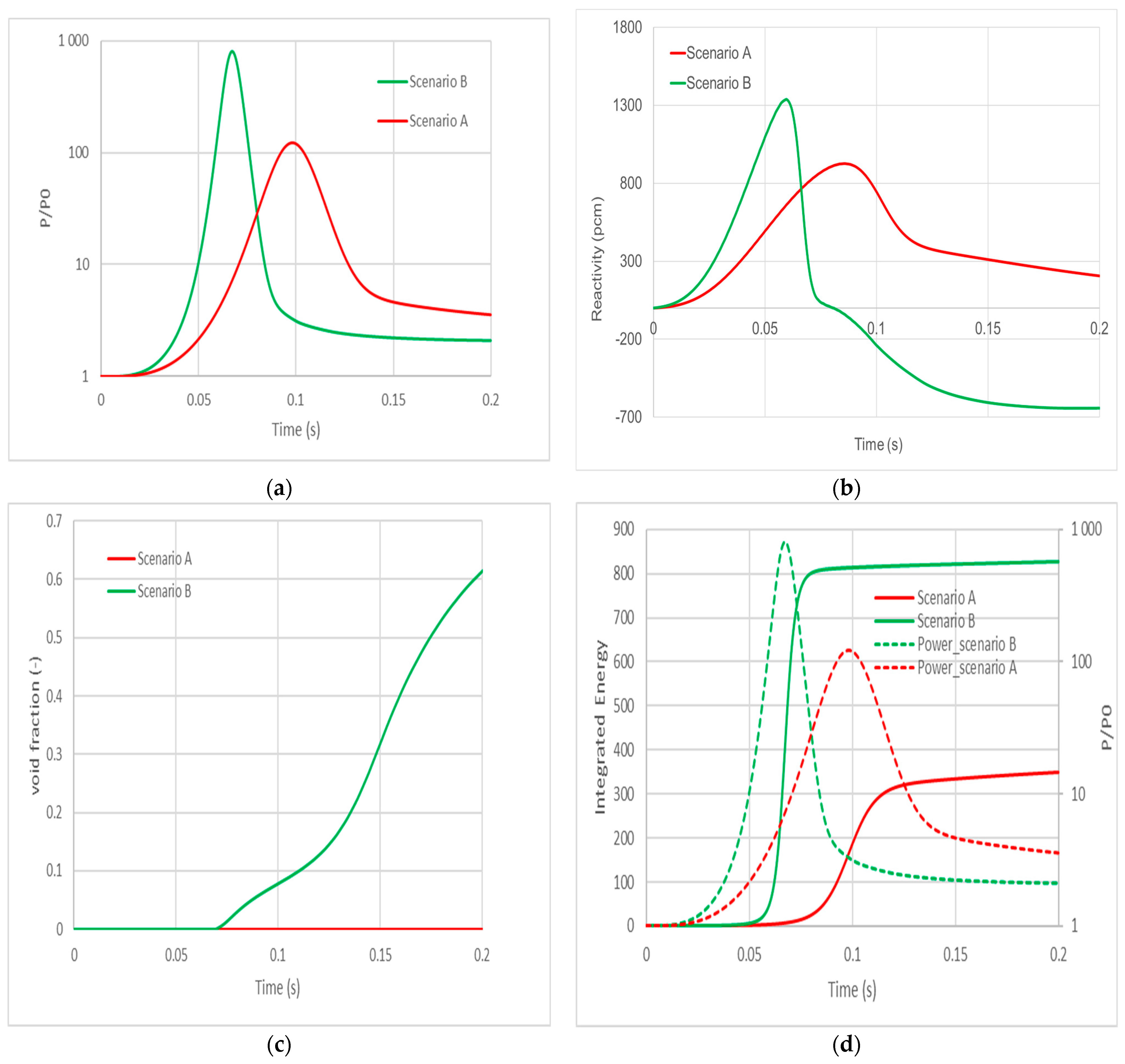
To illustrate the importance of initial conditions, two cases are presented in the paper (see Figure 5):
  • Scenario A: initial configuration with all CRs extracted except the one that will be ejected.
  • Scenario B: initial configuration with all CRs inserted. The rod ejected is the same as in Scenario A.
Scenario B is a very powerful theoretical case (reactivity inserted >> effective delayed neutron fraction) analyzed in the paper with the aim of challenging the codes and the couplings resolution in case of a moderator occurring liquid to two-phases transition. This case may allow for the analysis of the codes’ numerical algorithms and models under low-density conditions.
In both scenarios, the theoretical transient is simulated up to 2 s, and the automatic shutdown system is not simulated.
These transients have been extensively applied to the 32 FA PWR minicore case by adopting several boundary conditions and calculation options, as presented further in this paper. Some of those options have also been tested for the hexagonal geometry configuration.
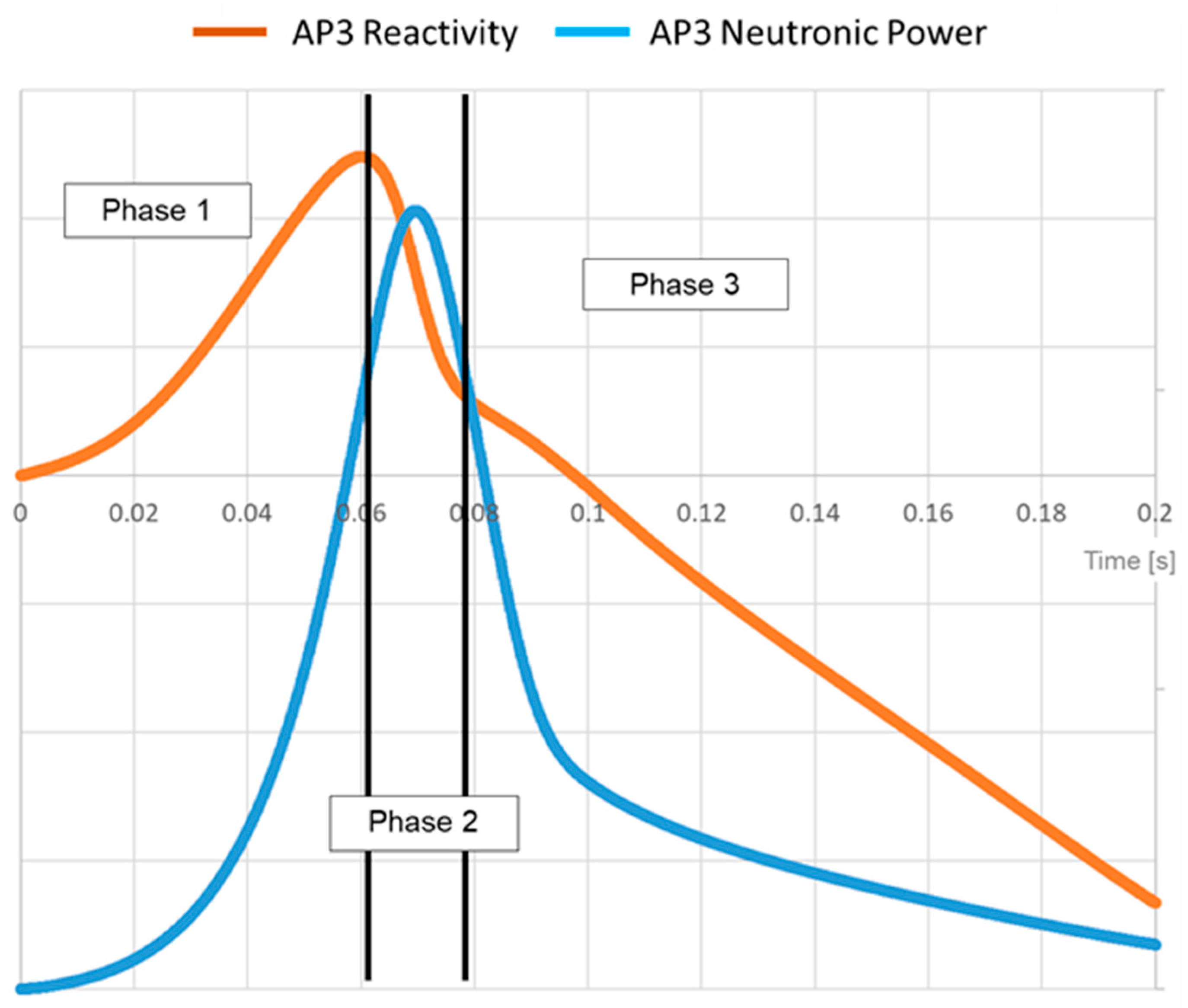
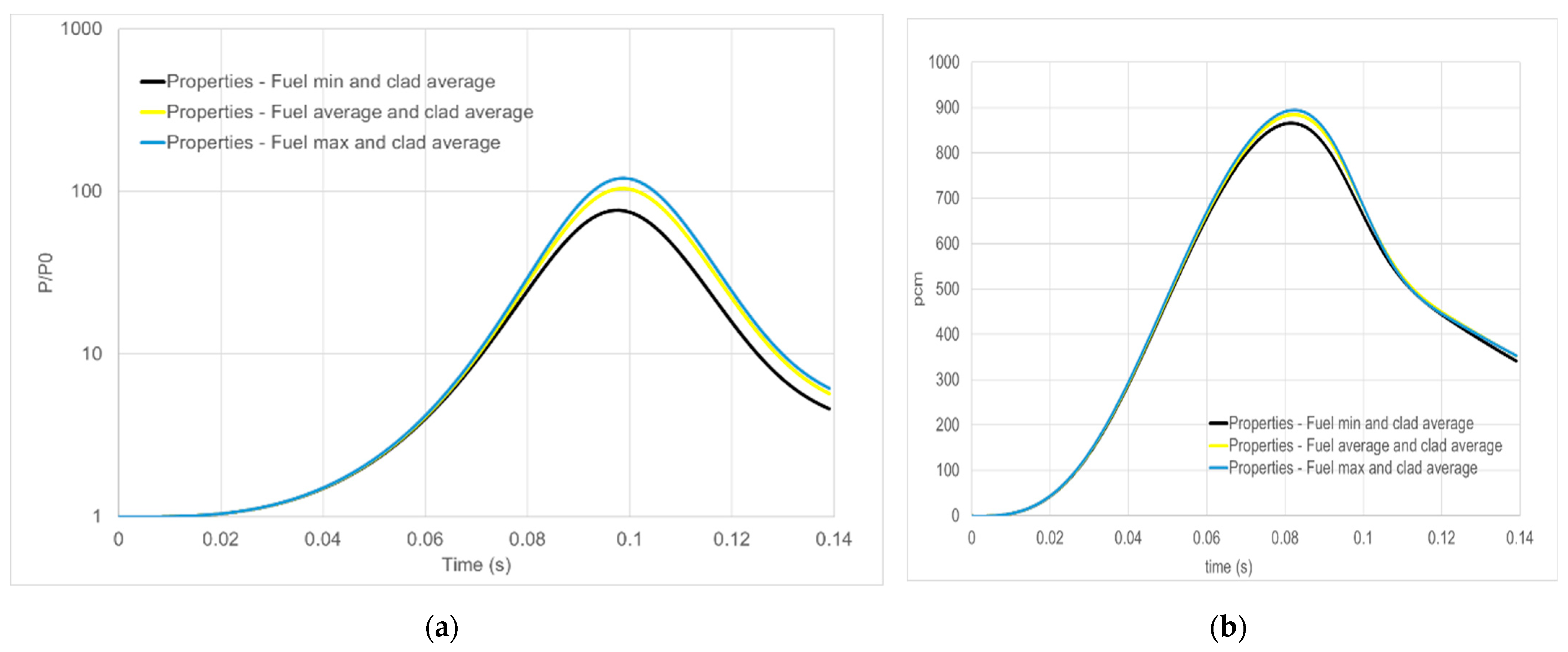
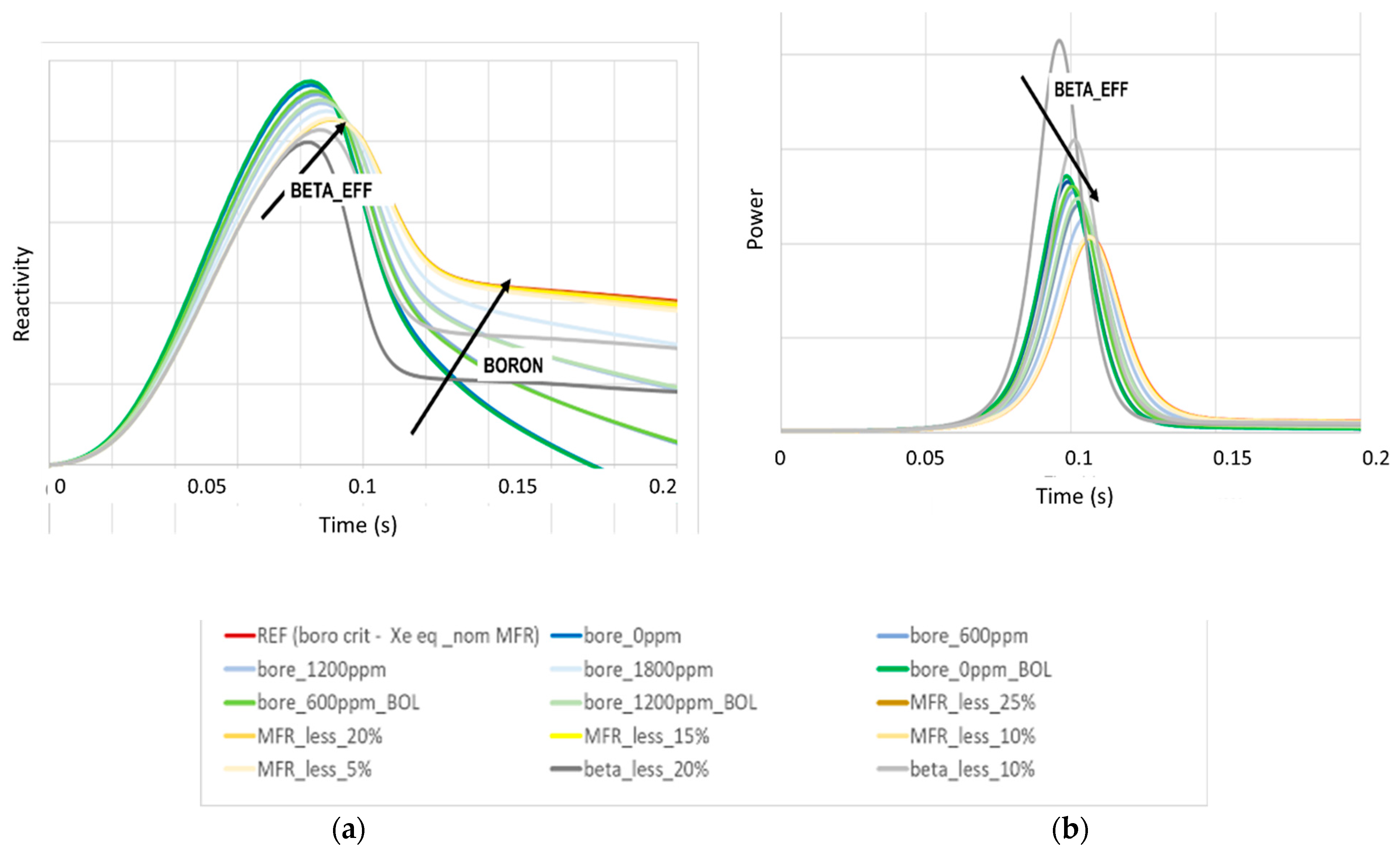
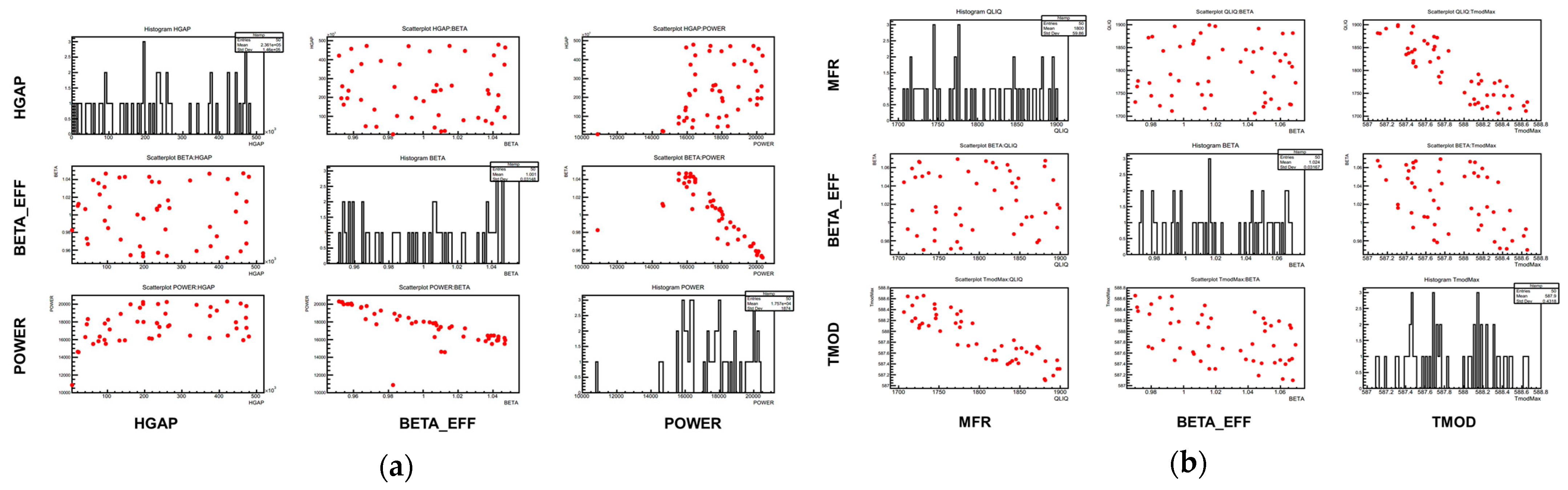
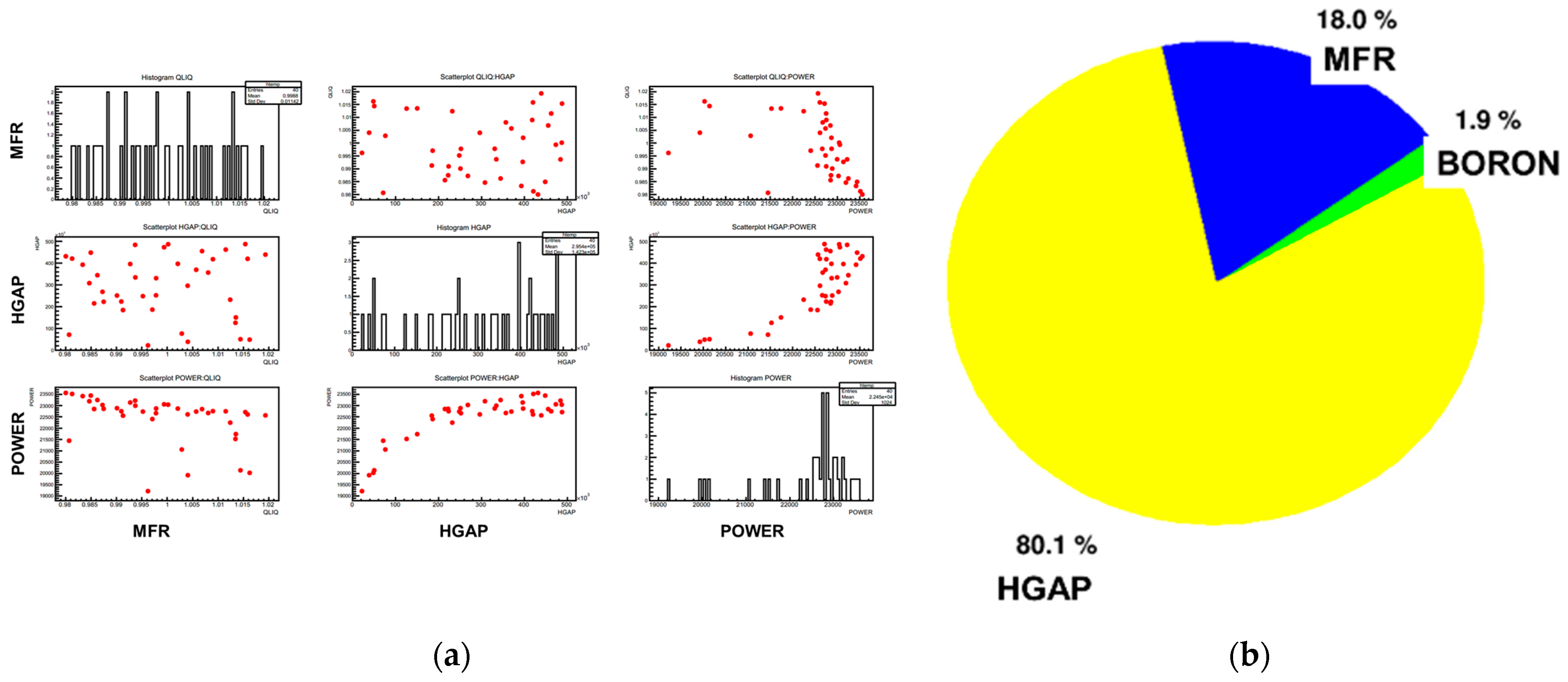
The kinetic transients have also been investigated by means of the URANIE statistical library for carrying on sensitivity analysis (SA) at different transient points. Qualitatively, three phases have been identified during the transients, as shown in Figure 6:
  • Phase 1: reactivity insertion, a phase characterized by the CR worth and the dynamic of the rod ejection.
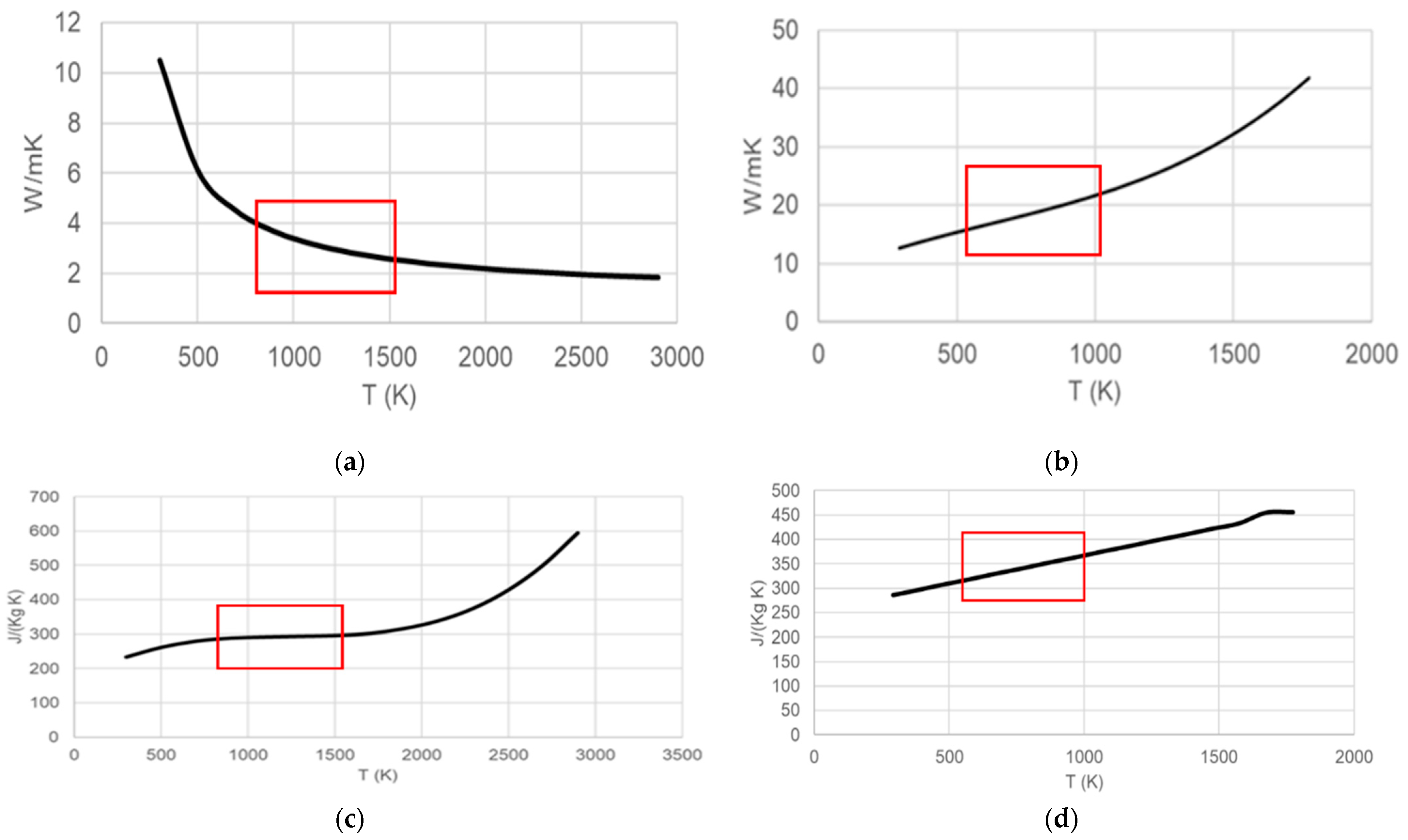
  • Phase 2: power peak, a phase characterized by the thermal fuel properties.
  • Phase 3: after the peak, the phase characterized by the thermal-hydraulics feedback.
Geometries Investigated in The Sensitivity Analysis
In order to investigate the interactions among phenomena impacting the cross-section preparation before analyzing the core behavior under steady-state and transient conditions, a step-by-step approach is proposed based on the URANIE [15] statistical library applied to APOLLO3® 2D and 3D calculations.
This step-by-step approach has been set up in support of the benchmark exercises proposed in the CAMIVVER Project, to make an easier investigation of discrepancies among codes, and to identify the dominant effects.
A set of important parameters and figures of merit typically found in parametric data libraries to estimate the contribution of such phenomena and input options to the core behavior, having as target objective the transient accidental safety analysis, has been treated and applied to several geometries (cell, assembly, cluster of assemblies and core geometry).
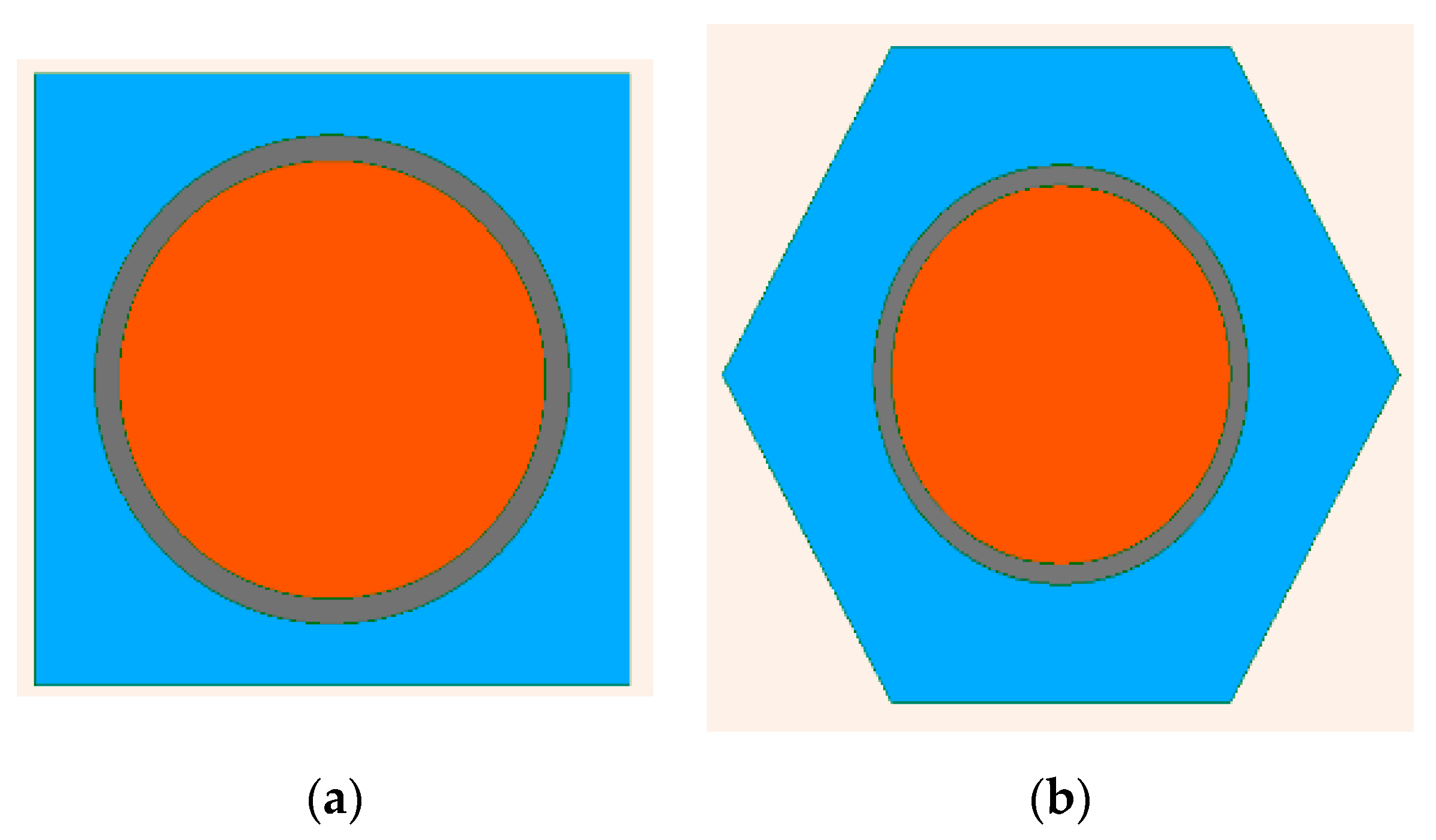
At the cell level, Cartesian and hexagonal 2D geometries have been selected, as indicated in Figure 7, based on Uranium Oxide (UOX) and Uranium–Plutonium Mixed Oxide (MOX) fuel materials. At the assembly level, only PWR configurations have been investigated, as indicated in Figure 8. Indeed, VVER geometry is not mandatory in terms of the CAMIVVER Project work program [2], wherein one of the objectives is the development of a multigroup cross-section library generator based on APOLLO3® to prepare core data for different reactor types (both PWR and VVER). The first version of the prototype able to treat PWR but also VVER configurations is expected by the end of 2022. PWR applications are already available, while VVER applications are not yet fully ready for carrying out this type of SA analysis.
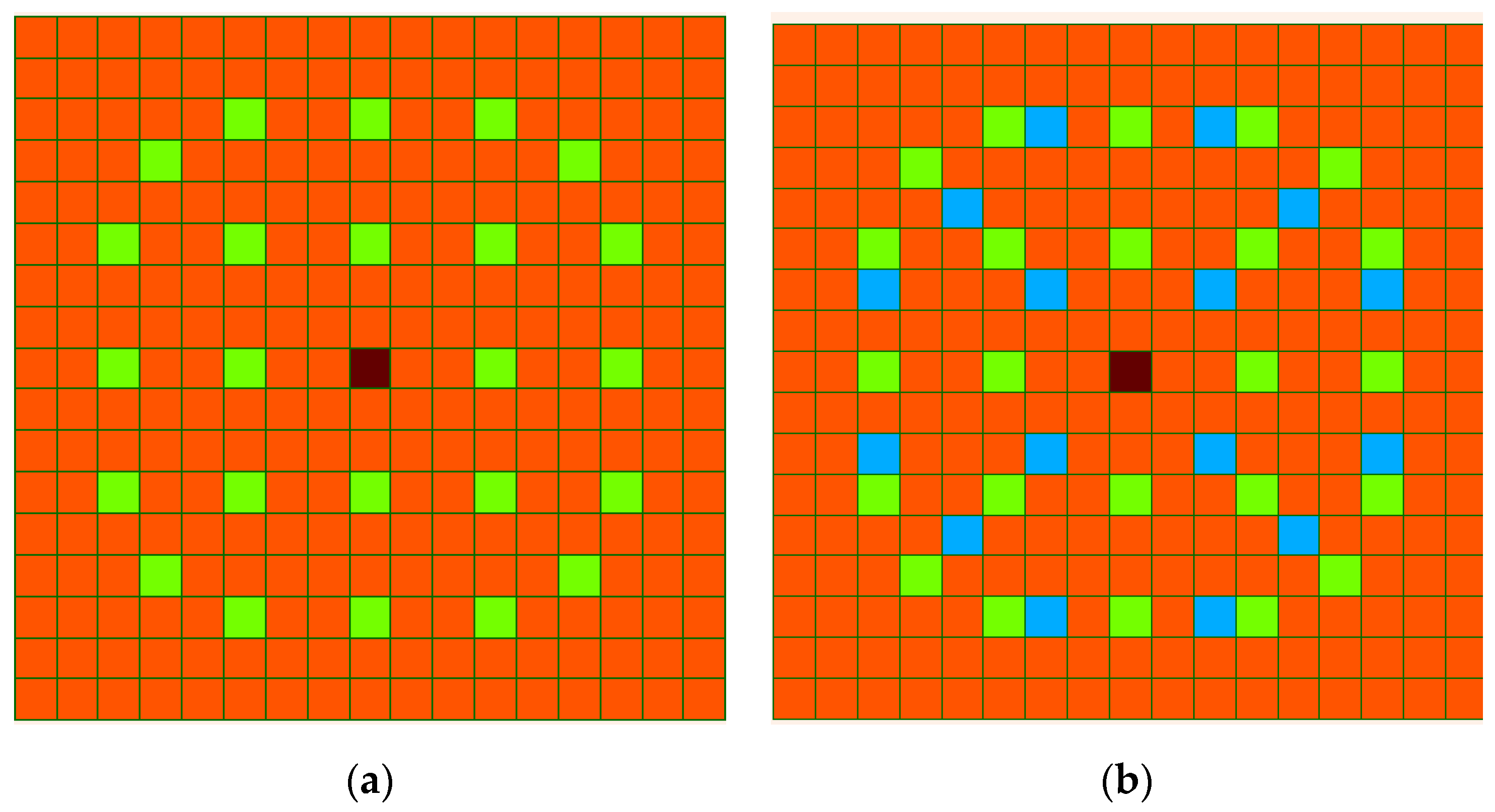
The 2D-UOX assembly configuration shown in Figure 8 is characterized by UOX enriched at 3.7% U235 and with dimensions coherent with the 32 FA minicore configuration described previously (see also Refs. [19,20]). The uranium–gadolinium assembly configurations (UGD) identified for having an additional case is characterized by 16 Gd pins as indicated in Figure 8b (blue zones). This configuration based on Ref. [24] has been added to broaden the analysis to other assembly cases and prepare the investigations toward heterogeneous core cases.
Lattice calculations are the first step of the so-called deterministic “two-step” approach where a spatially detailed multigroup flux solution at the fuel assembly level is used as reference flux to produce a few group homogenized cross-sections (multiparametric data libraries), which are provided as input to the 3D full-core calculation where the coupling of different physics determines the behavior of the systems.
For the sensitivity analysis, the parameters variation considered at the cell and assembly levels has been chosen to start the analysis of the components of a Multiparametric Output library (called MPO in the APOLLO3® environment), i.e., pre-tabulated cross-sections representative of hypothetical core states, which are then used for core steady-state and transient calculations in addition to other parameters describing technological data variation and operating conditions (see Table 5).
For the sensitivity analysis carried out and presented in the paper, the parameters chosen are:
  • Fuel temperature (FTEM): to take into account for reactivity effect by Doppler resonance broadening.
  • Xenon level (XENON): to model different saturation concentrations of fission products obtained for prolonged operation at different power levels. Xenon-135 is responsible for an important reduction in reactivity. Its equilibrium concentration can be derived by using the simplified chain of xenon-135 and iodine-135, being proportional to the power level.
  • Moderator density (DMOD): changes in the moderator’s density yield the moderator reactivity effect enough when coolant is in the subcooled regime at normal operation (in liquid state).
  • Boron concentration (BORON): to consider the presence of diluted boron in the coolant for reactor control.
  • Control-rod (CR): for considering the presence of different types of control rods for reactor control and shut-down.
  • For the MPO preparation, other parameters need to be added as:
  • Burn-up (BU): to model the isotopic composition during irradiation.
  • Pressure: In addition to the DMOD, a second variable becomes necessary at the onset of fast/anticipated transients until saturation is achieved. Pressure is recommended at times for the existing functions in the water property libraries (i.e., those provided by the International Association for the Properties of Water and Steam, IAPWS).
In the present SA, parameters more related to technological data as the enrichment (ENRI) or the Plutonium Content (PU_CONT) have been considered, as well as parameters related to the operating conditions as the water gap dimensions (WATER_GAP) and the cell pitch variation (CELL_PITCH).

2.2. Codes and Methods Adopted

In this paper, the codes used by Framatome to construct and fulfill the benchmarks are presented. The other codes used in the project are indicated in Refs. [2,5].
The approaches for multiphysics solutions adopted and tested by Framatome within the project are the following ones:
  • APOLLO3® lattice calculations based on the Method of Characteristics, MOC, and TDT-solver for flux resolution over a refined 2D assembly geometry.
  • APOLLO3®/THEDI core calculations used in order to investigate the multi-1D thermohydraulic feedback model available with the code and can treat single- and two-phase conditions. The 3D neutron flux resolution is based on the finite element method (FEM).
  • APOLLO3®/CATHARE3 is the proposed proof of concept under development in the framework of the CAMIVVER Project for the profiting of the 3D core capabilities of the CATHARE3 code and the recently developed C3PO coupling.
  • C3PO–Collaborative Code Coupling PlatfOrm: coupling engine allowing the use of different codes other than APOLLO3®, CATHARE3, etc.
APOLLO3®/THEDI
In the framework of the APOLLO3® Project [3], a new thermohydraulic model (THEDI—THErmohydraulique DIphasique) for internal coupling has been developed and integrated since September 2018 [3,18,25]. THEDI is a multi-1D, two-phase flow solver able to treat Cartesian and hexagonal (as VVER) geometries.
The THEDI thermohydraulic library is one-dimensional and solves a four-equation model composed of total mass conservation, vapor mass conservation, total motion equation and total internal energy conservation [25]. The core is treated as separated 1D channels that contain several solid objects, such as fuel rods. THEDI computes the temperature distribution in each of them by solving a one-dimensional heat transfer diffusion equation. THEDI is also able to compute the power evolution during a transient by solving the neutronic point kinetic equations [25].
APOLLO3® code [3] has been used either for lattice 2D calculation (based on the MOC, TDT-solver [26]) or for coupled-core 3D calculations.
APOLLO3®/CATHARE3
Within the CAMIVVER Project, the newly proposed APOLLO3®/CATHARE3 coupling based on the C3PO engine has been developed for benchmarking against existing 3D multiphysics models and High-Fidelity Monte Carlo solutions.
This approach was developed to improve the 3D capabilities of the CATHARE3 code in comparison to the multi-1D approach. This coupling is tested under RIA transient within the CAMIVVER project but may be extended to other applications.
C3PO (with Other Codes)
C3PO is a Python coupling platform initially developed by the CEA [27]. The C3PO application in CAMIVVER project aims to increase the robustness of the PWR industrial multiphysics couplings. C3PO enables the interchangeability of core neutronics and thermal-hydraulic codes.
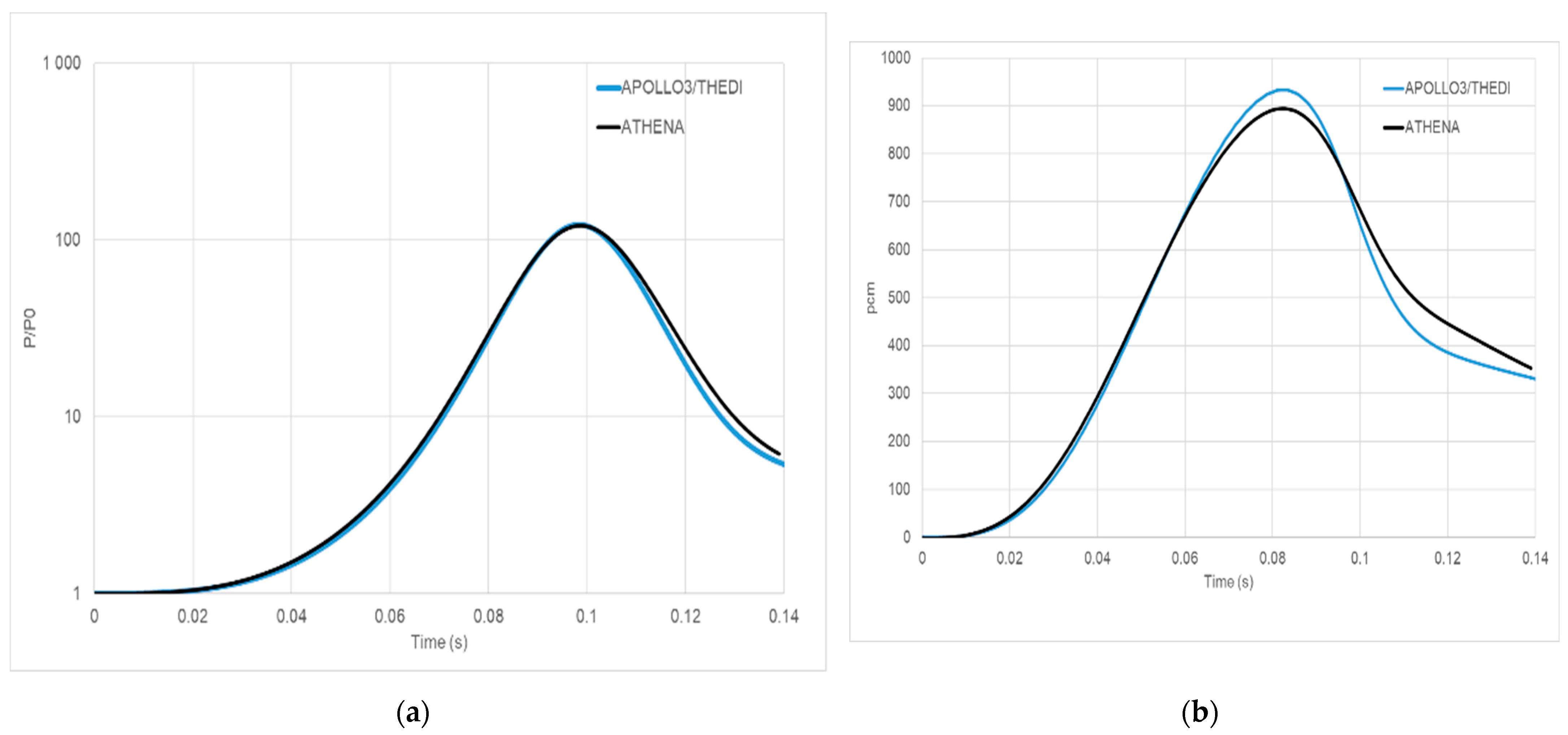
To consolidate the preliminary results from CAMIVVER project, an industrial coupling platform, ATHENA has been considered the benchmark in the present paper [16]. This multiphysics coupling platform is the result of recent developments co-realized by EDF (Electricité de France) and Framatome. It relies on a Python environment to control the execution of the different codes. It allows for a straightforward implementation of the Operator Split couplings between the solvers using their respective Python application programming interface (API).
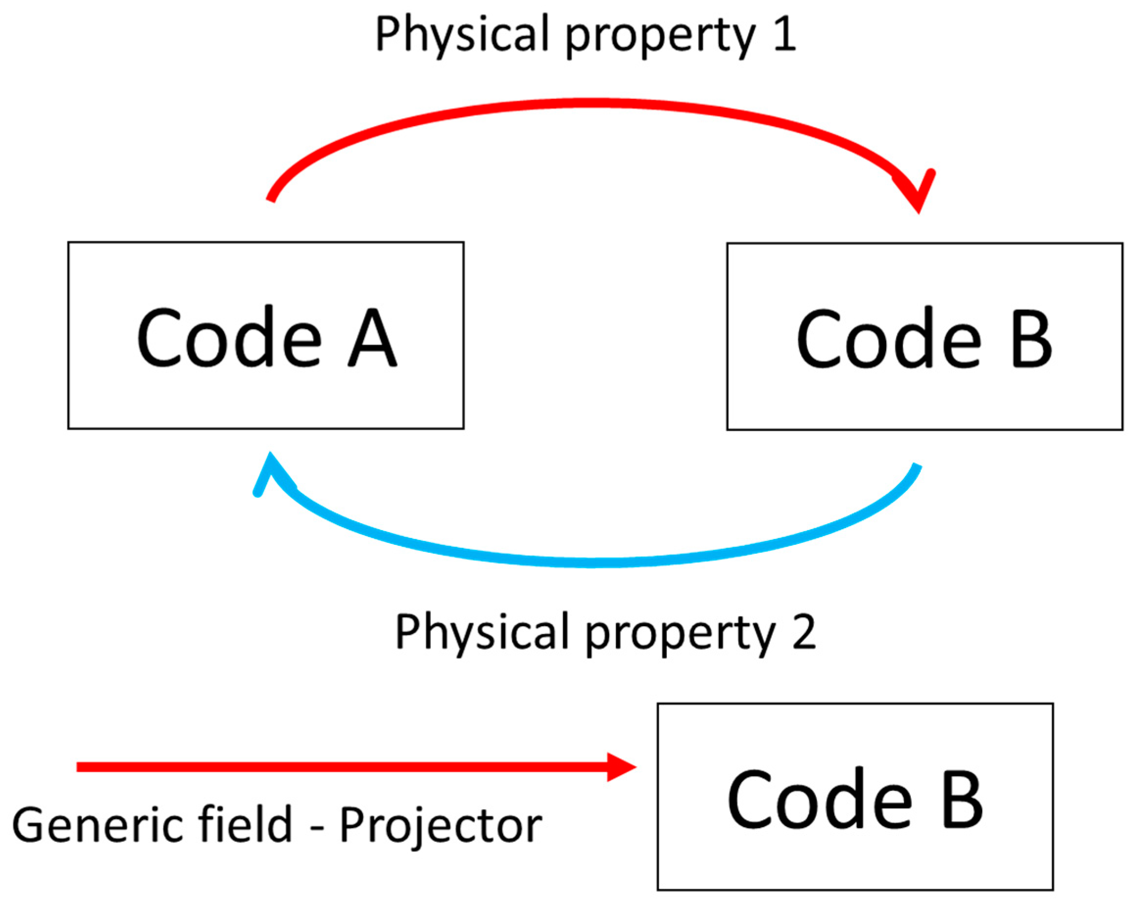
ATHENA has a modular structure, and it is based on an object-oriented programming approach. Moreover, it is a general-purpose coupling interface, and it uses a series of classes to exchange data among different codes, physical models, and spatial scales, as simplified in Figure 9 [16].
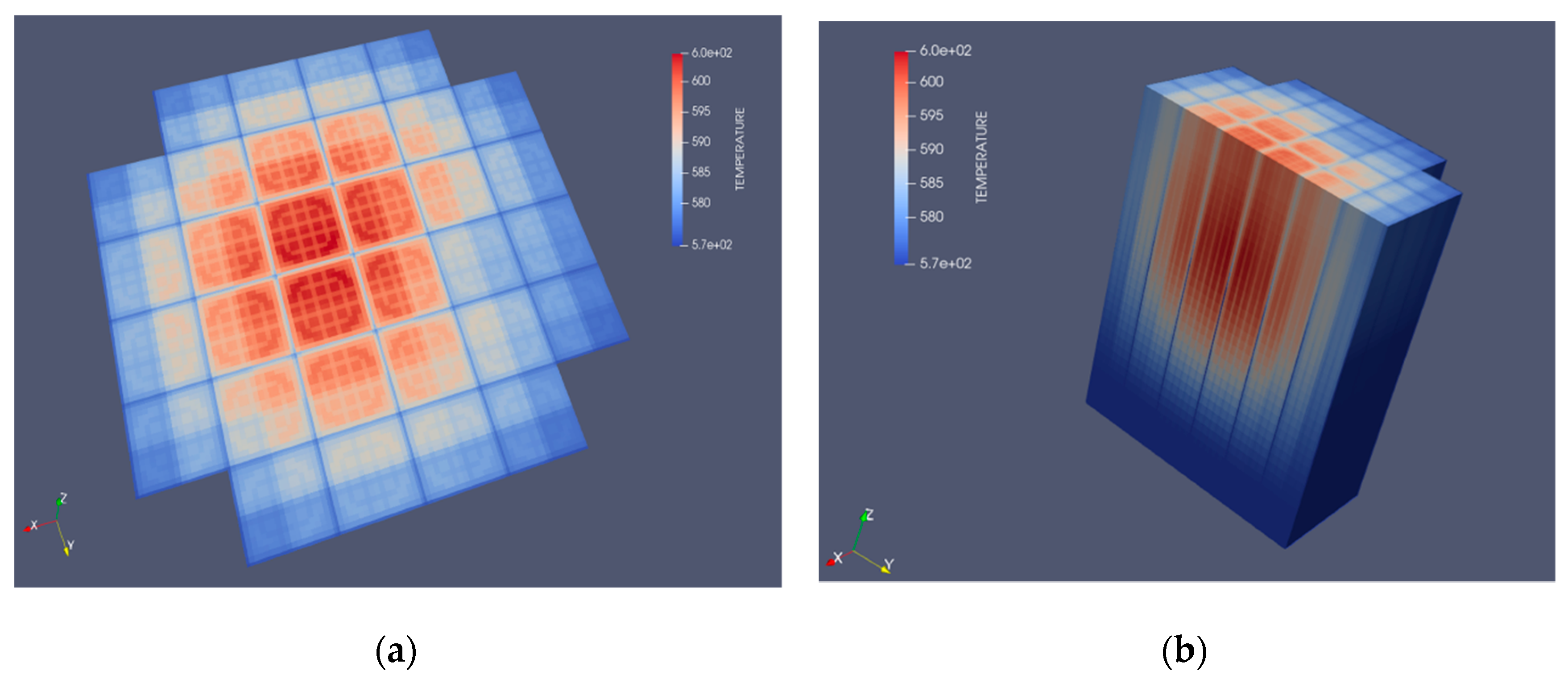
Some open-source Python libraries for data manipulation and interfaces (such as ICoCo API and MEDCoupling) are at the basis of coupling engines, and post-processing may be realized in 3D format for variables of interest.
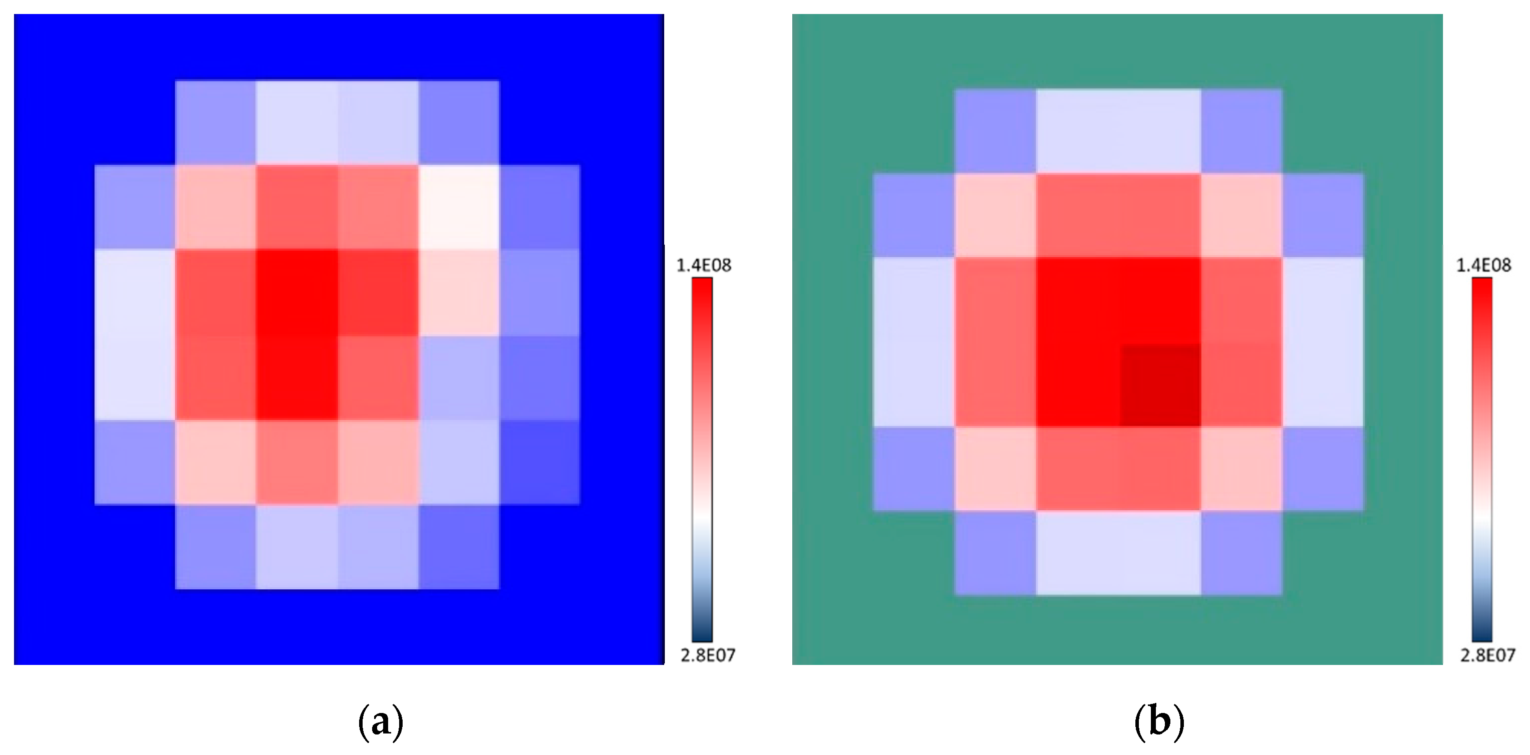
An overview of the 3D coolant temperature pin-by-pin distribution is presented in Figure 10.
URANIE
In addition to advanced coupling methods, the development of innovative solutions such as the high-fidelity Best-Estimate Plus Uncertainties (BEPU) methods are pursued at the industrial level. In the present paper, the uncertainty and sensitivity platform, URANIE, developed by the CEA, has been used [15].
URANIE aims to regroup several methods and algorithms for uncertainty and sensitivity analysis (SA) that are accessible to the user, thanks to the modular structure of the implemented libraries.
Only some of the libraries available in the URANIE Platform were used for the SA presented in this paper for application at the lattice and core steady-state as well as the transient calculations.

3. Results and Discussion

3.1. Preliminary Lattice Results

To prepare suitable data for the core steady-state and transient calculations (MPO libraries for assembly and reflectors zones), several analyses have been planned within the CAMIVVER project using the APOLLO3® code. Indeed, one of the objectives of the project is to have the first prototype version of the multiparametric library generator by the end of 2022 [1,5].
The availability of multiparametric libraries for core calculations is fundamental as well as the understanding of the impact on the core calculation of the variability of the quantities used in the procedure for preparing cross-sections as the moderator density, fuel temperature, etc. In order to have as many possible elements for analyzing the core behavior, a preliminary sensitivity analysis was carried out in the present paper looking at all components of a deterministic calculation approach (lattice to core calculations). The APOLLO3® code [3] and the URANIE statistical platform [15] were used and coupled to analyze the impact of several parameters selected at lattice and core levels.
As already indicated, in the industrially used “two steps” deterministic approach, the cross-sections are prepared and pre-tabulated in order to cover all of the nominal and transient core conditions. Typically, the data are tabulated as functions of burnup, moderator density, fuel temperature, Xenon, and boron concentration, etc., covering quite a large space of the phases that the core may achieve during normal and transient conditions. These tabulated data were used, after appropriate interpolation, to provide effective cross-sections at each core node in order to account for the 3D configuration and behavior in time [14,28].
For the lattice part, the parameters investigated and the geometries treated are described in Section 2.1 (Figure 7 and Figure 8, and Table 5).
The sensitivity analysis was performed at the cell level before considering the assembly configurations, which are commonly used for the multiparametric library preparation.
The 2D cell configuration, which is less consuming on calculation time, was chosen at the beginning to set up the environment of the URANIE-APOLLO3® coupling in a simplified case. The 2D cell configuration is somehow representative of the system and is typically used in V&V activities (i.e., comparison between deterministic vs. stochastic methods and nuclear data evaluation investigations). The results allow for some confidence with the URANIE-APOLLO3® coupling and to underline trends of the quantity of interest. Other configurations not presented here may also be tested; for instance, a cluster of assemblies as in Refs. [29,30] with the purpose of investigating the FAs interfaces.
The aim of those analyses is to investigate the overall deterministic calculation chain.
For the lattice part, the interest is on the macroscopic cross-section (fission, absorption, and scattering) and their evolution during core calculations due to fuel and coolant temperatures/densities changes that imply feedback (Doppler and moderator effects). In this paper, instead of analyzing the single multigroup cross-sections, it was decided to consider a global figure of merit as the k∞ (see Equation 1). This figure of merit is sufficient for the analysis proposed here and consistent with the choice made at the core level (see Section 3.2).
k DIFF = ( ν Σ f 1 + ν Σ f 2 Σ s 1 2 Σ a 2 ) Σ a 1 + Σ s 1 2
where ν is the average number of neutrons released per fission; Σ f 1 and Σ f 2 are, respectively, the neutron fission production rate integrated over space, energy and direction for the first and second energy group; Σ s 1 2 is the integrated scattering from group 1 to 2 production rate; Σ a 1 and Σ a 2   are the integrated absorption production rate for energy groups 1 and 2.
In the following part, the SA is presented for the three types of cells indicated in Figure 7 (PWR UOX, PWR MOX, and hexagonal UOX cells).
The parameters considered for the SA are listed in Table 6. Uniform distributions were used for this first exercise. The variations tested are theoretical variations based on engineering judgements for the purpose of the analysis. The analyses were carried out using 100–200 samples and mostly Simple Random Sampling (SRS), but also Latin Hypercube Sampling (LHS) methods, and were tested depending on the configuration.
PWR UOX CELL
Figure 11 shows the Pairs plot for the PWR UOX cell case with SA to fuel temperature, enrichment, and cell-pitch parameters. Figure 11 shows the expected linear dependence (increasing monotonous function) of the k∞ with respect to the cell-pitch variation (due to the fuel-to-moderato ratio) and the enrichment. The dependence on fuel temperature is less pronounced, but in Figure 11 (bottom-left graph) a slightly decreasing dependence of the k∞ may be distinguished.
The dependency on boron concentration has also been tested, as indicated in Figure 12. In this case, the linear behavior with respect to boron concentration is quite visible as expected (central subplot at the bottom of Figure 12). As can be seen in Figure 12, for some parameters, the perturbation was applied to a multiplication factor (e.g., BORON bottom-central graph) and not to the nominal value itself.
PWR MOX CELL
The PWR MOX Cell (average plutonium content of about 9.5%) main input parameters have been analyzed under the same variations as the PWR UOX cell in Figure 12. As can be seen in Figure 13, the dependence of the reactivity from the boron concentration variation is less pronounced than in UOX case as expected because of the spectra difference between UOX and MOX cells.
For the PWR MOX Cell, an additional parameter was analyzed to identify the voiding effect. To carry out this analysis, the moderator density (DMOD) was changed up to 20% of its nominal value, and the plutonium content increased above 12%. The variation on this parameter was maximized with respect to the other parameters considered in the SA. The UOX and MOX behaviors are shown in Figure 14. For the MOX case, it is possible to observe that the reactivity behavior is not monotonic with respect to the moderator density (perturbed via a multiplication factor applied to the nominal value). At a very low density, the reactivity for the MOX case starts to increase, while for the UOX case, the behavior remains decreasingly monotonic.
HEXAGONAL UOX CELL
The Hexagonal UOX Cell case was also treated. Figure 15 shows that also, in this case, an expected linear dependence of the k∞ with respect to the cell-pitch variation (due to the fuel-to-moderato ratio) is observed for the PWR UOX case (Figure 11). The effect of reactivity reduction related to the boron concentration increase is also indicated in Figure 15. To give a preliminary quantitative ranking of the parameters considered for the distributions assumed in Table 6, Figure 16 shows the pie-plot for the UOX and VVER cell types. The same ranking of the parameters was found for the two cases.
PWR UOX AND UGD ASSEMBLY
In this section, the analyses carried out at the 2D assembly level are presented. Two assembly types were investigated: an UOX case consistent with 32 FA minicore specifications (Section 2.1) and a UGD case.
For the assembly cases, the parameters considered for the SA are listed in Table 7. Uniform distributions were used for this exercise as well. The variations tested were theorical variations based on engineering judgements for the purpose of this analysis. As for the cell cases, 100–200 samples and mostly Simple Random Sampling (SRS) but also Latin Hypercube Sampling (LHS) methods, depending on the configuration, were considered.
As shown in Figure 17, the linear behavior of the k∞ with respect to the boron content already identified at the cell level was confirmed, as expected, at the assembly calculation. The dominance of the boron here is more significant than in Figure 13 due to the larger variation imposed on the assembly case (±5%/±20% vs. ±1.5% used at the cell level). The boron variation is indicated in Figure 17 by the perturbation of the multiplication factor applied to the nominal value.
Other parameters considered in the MPO preparation as the Xenon content were analyzed at the assembly level. The variations assumed were between 0 to saturated level in agreement with the power density indicated in Ref. [20]. The variation due to the Xe saturation is about ~1800 pcm, which is, therefore, dominant with respect to the other parameters.
The same considerations have been carried out for UGD assemblies coming to the same conclusions.
More investigations are planned to open the analysis of single multigroups cross-sections and other assemblies’ cases (i.e., configurations with control rods and MOX with different plutonium qualities). Other lattice codes and statistical libraries may be included in this comparison.

3.2. Core Calculations: 32 FA Minicore Case

STEADY-STATE AND TRANSIENT PRELIMINARY RESULTS
In the following part, the preliminary results obtained at Framatome for the 32 FA PWR minicore case are presented. The main purpose of this exercise is to analyze and rank the sources of discrepancies among the codes and methods that are planned to be applied within the CAMIVVER Project.
Such codes use different methods either in the preparation of the suitable cross-sections but also in the neutronics and thermal-hydraulics equations resolutions. Several modeling options (up to the High-Fidelity Monte Carlo calculations used by other CAMIVVER partners) may be considered and may impact the transient results.
In order to identify the sources of discrepancies, the first comparison was carried out under steady-state conditions for the 32 FA PWR minicore case.
In this analysis, Framatome compared the codes used within the CAMIVVER project (APOLLO3®/THEDI and APOLLO3®/CATHARE3) with the newly developed coupling (ATHENA) that is part of the EDF and Framatome next-generation core physics computer code package ODYSSEE [16]. ATHENA allows coupling between the core 3D neutronic solver of COCAGNE and the core 3D TH code THYC. The nuclear data for this comparison are produced with the APOLLO2 code [28] using the JEFF3.1.1 data.
The main results on the initial steady-state for Scenario A (initial configuration representatives of all CRs extracted except the one that will be ejected) are given in Table 8. The reactivity of the ejected control rod is about $1.2 (dollar ($) is the unit of the reactivity normalized to the delayed neutron fraction) for Scenario A.
The activities for preparing a suitable MPO for fuel assembly and reflector zones are ongoing in CAMIVVER project, and test libraries only generated via the MPOGen tool [31] have been used for these preliminary calculations. In order to make some comparisons, two configurations have been studied in this paper: the standard 32 FA minicore case with and without axial reflectors. The case without a reflector allows for reducing the discrepancies between the APOLLO3®/THEDI and ATHENA (from 120 to 38 pcm) waiting for fully converged reflector nuclear data libraries (under construction in the CAMIVVER project). The difference between the two codes in the case of the core without CR was 10 pcm, which is good agreement with the fuel library preparation between APOLLO3® and APOLLO2. The difference in the CR weight, as indicated in Table 8 of about 3% may be related to the calculation scheme adopted at the lattice level between APOLLO3® (calculation scheme not yet optimized) and APOLLO2 (industrial calculation scheme). This discrepancy remains acceptable, as also indicated in Ref. [30] where several options are compared concerning the modelling of the Ag-In-Cd control rod type. More investigations are planned in the CAMIVVER project to deeply analyze this discrepancy.
In order to get more information about the difference between the two codes, the effect of the control rod position on criticality (S-Curve) was assessed as indicated in Figure 18 for the cases with and without axial reflectors. Figure 18 confirms a good agreement between the two codes.
Scenario B was characterized by a much stronger reactivity insertion (larger than $2) has also been investigated with APOLLO3®, with the aim of analyzing the moderator transition to one-phase to two-phase flow regimes (see Table 8). Scenario B allowed for the testing of the codes under more challenging transient conditions. The comparison between Scenario A and B is shown in Figure 19 using the APOLLO3®/THEDI code. The obtained preliminary results show that the code is able to catch the transition of the two-phase coolant flow experienced after a stronger power increase, which brought a sharp reduction to the reactivity, as indicated in Figure 19b. The higher power peak in Scenario B brought the development of the two-phase flow, as indicated in Figure 19c. The difference between the two Scenarios, A and B, may also be appreciated in the analysis shown in Figure 19d that was provided by the integrated energies.
More investigations were carried out in Scenario A. The impact of the axial reflector modeling on the power and reactivity trends is shown in Figure 20. The behavior of the reactivity inserted during the RIA transient (APOLLO3®/THEDI results are in Figure 20b) follows the behavior of the static calculations indicated in Figure 18. The power trends show a reduction of the maximum value when the axial reflectors are removed. The same behavior was obtained by the ATHENA calculations.
The code comparisons are shown in Figure 21. The power trend is in very good agreement, as indicated in Figure 21a. The reactivity behavior, Figure 21b, is in very good agreement during the first part of the transient (in accordance with Figure 18a static calculations), but some discrepancies are observed approaching the maximum reactivity value. The differences after 0.1 s, namely after the end of the neutronic perturbation due to the CR extraction, may be due to the difference in thermal-hydraulic feedback treatments (multi 1D approach for APOLLO3®/THEDI and 3D approach for ATHENA).
Other sources of differences identified between the two codes are the thermal properties adopted. For the APOLLO3/THEDI calculations, temperature-dependent properties have been used (see Figure 22) in agreement with Ref. [19], while for the ATHENA preliminary calculations, constant properties have been adopted. Preliminary investigations on the impact of thermal properties were carried out in terms of the interval of variation of the Fuel and Cladding temperature and thermal properties during transient (red boxes in Figure 22). The impact of thermal fuel properties is important for the power peak (env. 15%) while remaining acceptable on the reactivity variation (Figure 23). The discrepancy indicated in Figure 23b may be due to a slightly different Doppler effect. More investigations are ongoing to consolidate the results.
For the 32 FA minicore case, the power distribution at the beginning and at the end of the simulated transient is presented in Figure 24. Figure 24a shows an asymmetric assembly power distribution due to the CR inserted while at the end of the transient, when CR is fully extracted, a more symetrical behavior may be observed (Figure 24b).
Preliminary calculations with the under-development coupling APOLLO3®/CATHARE3 were also carried out. The analyses presented in Figure 25 are preliminary, and the results will be improved during the follow-up of the project by the end of 2023. Several options have been set up to test the coupled approach. Figure 25 shows differences of about 10% in the power peak that will be investigated in the follow-up of the project.

3.3. Core Calculations: 19 Hexagonal FA Core Case

Preliminary analyses were also conducted for a hexagonal configuration to open the discussion to other reactor types, such as VVER. A 19 FA core case loaded with the same FA type was set up, and a RIA transient was run (Figure 26). The power distribution at the beginning and at the end of the simulated transient is presented in Figure 27; in this case, it is visible the asymmetric assembly power distribution at the beginning of the transient (i.e., CR inserted) and a more symmetric distribution at the end of the transient. As for the 32 FA PWR minicore configuration, the impact of the axial reflector modeling on the reactivity trends was analyzed, as shown in Figure 28. The behavior on reactivity is comparable to what is shown in Figure 20b.
These preliminary results obtained for the VVER configuration are reasonable, and they align with the capabilities of the codes used for the western PWR application in treating other kinds of reactor types.
SENSITIVITY ANALYSIS (SA) AT CORE LEVEL
In addition to the transient investigations described in the previous part, a SA based on the same codes used at the cell and assembly level (APOLLO3® and URANIE) was carried out at core transient conditions. The APOLLO3®/THEDI coupling is used for the 3D core calculations using two energy groups’ diffusion approximation.
Before applying a statistical library with an automatic variation of the selected input options and models, a parametric study was performed on a restricted number of calculations looking for envelope behaviors and the impact of the selected input data on some figures of merit. The results obtained by this parametric study are shown in Figure 29, which qualitatively presents how the effectively delayed neutron fraction (see BETA_EFF in Figure 29) variation is dominant in the maximum power during the transients (see Phase 2 in Figure 6) and how the boron concentration impacts the final part of the transient (see Phase 3 on Figure 6).
The impact of parameters and ranking on the trends has been analyzed by applying the statistical library, URANIE. The parameters considered for the SA are listed in Table 9. Uniform distributions are used for this exercise as well. The variations tested are theorical variations based on the engineering judgements for the purpose of the analysis. The SA has been carried out considering more than 100 samples and mostly Simple Random Sampling (SRS), but also Latin Hypercube Sampling (LHS) methods were tested.
At the core level, several figures of merit (reactivity, power, and moderator temperature) were considered to analyze the transient behavior during the different phases defined in Figure 6.
At the core level, a ranking of the first attempt is provided with a design of experiment (DOE) created automatically by URANIE for the selected parameters. It is observed that important limitations exist concerning the monotone and linear behavior of input parameters. Further improvement will concern the integration of more robust ranking methods to the proposed integrated multiphysics sensitivity analysis approach.
Figure 30 shows the core maximum power variation and the coolant maximum temperature variation evaluated against the parameter’s variation as indicated in Table 9. The core maximum power variation is mainly affected by the effective delayed neutron fraction (BETA_EFF), while the coolant maximum temperature variation is mainly impacted by the coolant mass flow rate (MFR).
The 19 Hexagonal FA core case was also analyzed. The idea is to have the tools running under different configurations in order to support the benchmarks proposed within the CAMIVVER Project. The impact on the maximum of power is shown in Figure 31, where the Pairs Plot and the Total Sensitivity Index are presented. The major impact of the gap conductance (Hgap) compared to MFR and boron on the maximum power is confirmed.
Figure 30 and Figure 31 confirm by a statistical approach the trends obtained by the parametric study of Figure 29.
More investigations are expected as well as comparisons with other codes and coupling calculation options. The adoption of different statistical libraries may also be considered to consolidate these results.

4. Conclusions and Perspectives

The paper focuses on the activities carried out by Framatome within the H2020 CAMIVVER project, showing the benchmarks defined as well as preliminary results obtained.
To support the industrial applications and the long-term strategy, new generation codes were selected for carrying out activities within the H2020 CAMIVVER Project. Framatome is involved in the development and improvement of 3D-multiphysics couplings concerning APOLLO3® and CATHARE3 codes. Multiscale and multiphysics solutions are key topics to keep competitiveness and to answer to newer industrial needs in plant operation, licensing, and safe operating envelope requirements; this is the reason why several actions were carried out for supporting comparisons to High-Fidelity codes.
The paper presents a reactivity insertion accident (RIA) proposed for a benchmark in the CAMIVVER Project, but it also opens to sensitivity analysis carried out for detecting and ranking the sources of discrepancies among codes. For analyzing the discrepancies, an integrated approach is proposed starting from lattice calculations up to core transient applications. This innovative integrated multiphysics sensitivity analysis supports the code robustness, ranking phenomena, and coupling validation.
More investigations are expected as well as comparisons with other codes and coupling calculation options before the end of the CAMIVVER Project. The SA investigations may be improved by profiting from other methods implemented in the URANIE code and by considering a series of surrogate models representing the lattice behavior and its uncertainties to be used as input options for core calculations, as well as the inclusion of other figures of merit (e.g., safety criteria and safety operating envelop and margins).

Author Contributions

Conceptualization, validation, and investigation B.C. and B.V.; methodology, B.C.; data curation, B.C. and B.V.; writing—original draft preparation, B.V. and B.C.; writing—review and editing, B.C. and B.V. All authors have read and agreed to the published version of the manuscript.

Funding

The H2020 CAMIVVER Project received funding from the Euratom Research and Training Programme 2019–2020 under grant agreement No. 945081. The authors would like to thank the APOLLO3® development team for their efforts in developing the code. APOLLO3® is a registered trademark of the CEA developed under the long-term partnership and support of EDF and Framatome.

Informed Consent Statement

Not applicable.

Data Availability Statement

The data will be following the Data Management Plant of the CAMIVVER Project This plan is under preparation.

Acknowledgments

Special thanks to our colleagues for the exchanges during the CAMIVVER project. Thanks to our Framatome colleagues, including Laurent Graziano, Clement Lafaurie, Denis Verrier, Alexandre Chea, Alberto Previti, Alberto Brighenti, and Damien Raynaud, for the exchanges on APOLLO3 ® and CATHARE3 codes. We also thank our CEA colleagues, including Roland Lenain, Paolo Cattaneo, Daniele Tomatis, Simone Santandrea, and Pietro Mosca. Special thanks also to KIT and EDF partners of the CAMIVVER project, including Luigi Mercatali, Juan Blanco, Diego Ferraro, and Adrien Willien.

Conflicts of Interest

The authors declare no conflict of interest.

References

  1. CAMIVVER Project. Available online: http://www.camivver-h2020.eu/ (accessed on 3 March 2022).
  2. CAMIVVER Project. H2020 Project, Grant Agreement Number: 945081, NFRP-2019-2020. Available online: https://cordis.europa.eu/project/id/945081/ (accessed on 30 March 2022).
  3. Schneider, D.; Dolci, F.; Gabriel, F.; Palau, J.M.; Guillo, M.; Pothet, B.; Bourhrara, L.; Buiron, L.; Coste-Delclaux, M.; De Saint Jean, C. APOLLO3®: CEA/DEN deterministic multi-purpose code for reactor physics analysis. In Proceedings of the PHYSOR2016 Conference, Sun Valley, ID, USA, 1–5 May 2016. [Google Scholar]
  4. CATHARE Project. Available online: https://cathare.cea.fr/ (accessed on 3 March 2022).
  5. Verrier, D.; Vezzoni, B.; Calgaro, B.; Bernard, O.; Previti, A.; Lafaurie, C.; Hashymov, A.; Groudev, P.; Stefanova, A.; Zaharieva, N.; et al. Codes and Methods Improvements for VVER Comprehensive Safety Assessment: The Camivver H2020 Project. In Proceedings of the 28th International Conference on Nuclear Engineering (ICONE28), Virtual Conference, 4–6 August 2021. [Google Scholar]
  6. Keyes, D.E.; McInnes, L.C.; Woodward, C.; Gropp, W.; Myra, E.; Pernice, M.; Bell, J.; Brown, J.; Clo, A.; Connors, J.; et al. Multiphysics Simulations: Challenges and Opportunities. Int. J. High Perform. Comput. Appl. 2013, 27, 4–83. [Google Scholar] [CrossRef] [Green Version]
  7. Fiorina, C.; Clifford, I.; Aufiero, M.; Mikityuk, K. GeN-Foam: A novel OpenFOAM® based multi-physics solver for 2D/3D transient analysis of nuclear reactors. Nucl. Eng. Des. 2015, 294, 24–37. [Google Scholar] [CrossRef]
  8. Fiorina, C.; Hursin, M.; Pautz, A. Extension of the GeN-Foam neutronic solver to SP3 analysis and application to the CROCUS experimental reactor. Ann. Nucl. Energy 2017, 101, 419–428. [Google Scholar] [CrossRef]
  9. Cervi, E.; Lorenzi, S.; Luzzi, L.; Cammi, A. Multiphysics analysis of the MSFR helium bubbling system: A comparison between neutron diffusion, SP3 neutron transport and Monte Carlo approaches. Ann. Nucl. Energy 2019, 132, 227–235. [Google Scholar] [CrossRef]
  10. Tiberga, M.; de Oliveira, R.G.G.; Cervi, E.; Blanco, J.A.; Lorenzi, S.; Aufiero, M.; Lathouwers, D.; Rubiolo, P. Results from a multi-physics numerical benchmark for codes dedicated to molten salt fast reactors. Ann. Nucl. Energy 2020, 142, 107428. [Google Scholar] [CrossRef]
  11. Permann, C.J.; Gaston, D.R.; Andrš, D.; Carlsen, R.W.; Kong, F.; Lindsay, A.D.; Miller, J.M.; Peterson, J.W.; Slaughter, A.E.; Stogner, R.H.; et al. MOOSE: Enabling massively parallel multiphysics simulation. SoftwareX 2020, 11, 100430. [Google Scholar] [CrossRef]
  12. Guide N°28 ASN. Available online: https://www.asn.fr/espace-professionnels/installations-nucleaires/centralesnucleaires/guides-de-l-asn/guide-de-l-asn-n-28-qualification-des-outils-de-calcul-scientifique-utilises-dans-lademonstration-de-surete-nucleaire (accessed on 3 March 2022).
  13. SNE-TP, Strategic Research and Innovation Agenda. Available online: https://snetp.eu/wp-content/uploads/2020/05/Strategic-Research-and-Innovation-Agenda-February-2013.pdf (accessed on 3 March 2022).
  14. Kerkar, N.; Paulin, P. Exploitation des Cœurs REP; EDP Sciences: Les Ulis, France, 2008; ISBN 978-2-86883-976-3. [Google Scholar]
  15. Gaudier, F. URANIE: The CEA/DEN Uncertainty and Sensitivity platform. Procedia Soc. Behav. Sci. 2021, 2, 7660–7661. [Google Scholar] [CrossRef] [Green Version]
  16. Acosta, F.; Lafaurie, C.; Monti, L.; Calgaro, B.; Kerdraon, D.; Le Coupanec, E.; Belblidia, L. Development and Application of a Novel 3D Neutron Kinetics and Thermal-Hydraulic Coupling within the Odyssee System. In Proceedings of the 19th International Topical Meeting on Nuclear Reactor Thermal Hydraulics (NURETH-19), Brussels, Belgium, 6–11 March 2022. [Google Scholar]
  17. Sanchez-Espinoza, V.H.; Mercatali, L.; Leppänen, J.; Hoogenboom, E.; Vocka, R.; Dufek, J. The Mcsafe Project-High-Performance Monte Carlo Based Methods for Safety Demonstration: From Proof of Concept to Industry Applications. In PHYSOR2020 Conference, Web of Conferences; EDP Sciences: Les Ulis, France, 2021. [Google Scholar] [CrossRef]
  18. Patricot, C.; Lenain, R.; Caron, D. Upgrade of Apollo3® Internal Thermohydraulic Feedback Model with Thedi, and Application to a Control-Rod Ejection Accident. In Proceedings of the M&C 2019 Conference, Portland, OR, USA, 25–29 August 2019. [Google Scholar]
  19. H2020 CAMIVVER: D5.1-Description of the Core Reference Test Cases—Part 1. Available online: http://www.camivver-h2020.eu/src/assets/doc/D5-1.pdf (accessed on 2 March 2022).
  20. H2020 CAMIVVER: D4.3-Definitions of Tests Cases for the Verification Phases of the Multi-Parametric Library Generator. Available online: http://www.camivver-h2020.eu/src/assets/doc/D4-3.pdf (accessed on 2 March 2022).
  21. Demaziere, C. Multiphysics Modelling to Optimize Design and Safety of Advanced Nuclear Reactors. In Proceedings of the IAEA Webinar Series on Nuclear Technology Breakthroughs for the 21st Century; 17 March 2021. Available online: https://www.iaea.org/nptd-webinars/1-multiphysics-modelling-to-optimize-design-and-safety-of-advanced-nuclear-reactors (accessed on 2 March 2022).
  22. Lötsch, T.; Kliem, S.; Bilodid, E.; Khalimonchuk, V.; Kuchin, A.; Ovdienko, Y.; Ieremenko, M.; Blank, R.; Schultz, G. The X2 benchmark for VVER-1000 reactor calculations. Overview and current status. In Proceedings of the 26th AER Symposium on VVER Reactor Physics and Reactor Safety, Helsinki, Finland, 10–14 October 2016. [Google Scholar]
  23. Ivanov, K.; Avramova, M.; Kamerow, S.; Kodeli, I.; Sartori, E.; Ivanov, E.; Cabellos, O. Benchmarks for Uncertainty Analysis in Modelling (UAM) for the Design, Operation and Safety Analysis of LWRs; NEA/NSC/DOC(2013)7; Organisation for Economic Co-Operation and Development: Paris, France, 2013; Volume I. [Google Scholar]
  24. Coppolani, P.; Hassenboelher, N.; Joseph, J.; Petetrot, J.; Py, J.; Zampa, J. La Chaudière des Réacteurs à eau Sous Pression; EDP Sciences: Les Ulis, France, 2004; ISBN 2-86883-741-7. [Google Scholar]
  25. Patricot, C. THEDI: A multi-1D two-phase flow solver for neutronic codes. In Proceedings of the ICAPP2019 Conference, Juan-les-Pins, France, 12–15 May 2019. [Google Scholar]
  26. Santandrea, S.; Sanchez, R. Acceleration techniques for the characteristic method in unstructured meshes. Ann. Nucl. Energy 2002, 29, 323–352. [Google Scholar] [CrossRef]
  27. C3PO. Available online: https://sourceforge.net/projects/cea-c3po/ (accessed on 2 March 2022).
  28. Sanchez, R.; Zmijarevi, I.; Coste-Delclaux, M.; Masiello, E.; Santandrea, S.; Martinolli, E.; Villate, L.; Schwartz, N.; Guler, N. Apollo2 Year 2010. Nucl. Eng. Technol. 2010, 42, 474–499. [Google Scholar] [CrossRef] [Green Version]
  29. Gamarino, M.; Dall’Osso, A.; Lathouwers, D.; Kloosterman, J.L. Rehomogenization of Nodal Cross Sections via Modal Synthesis of Neutron Spectrum Changes. Nucl. Sci. and Eng. 2018, 190, 1–30. [Google Scholar] [CrossRef] [Green Version]
  30. Santandrea, S.; Vezzoni, B.; Graziano, L.; Zmijarevic, I. Best Estimate Schemes in Lattice Calculations for Industrial Cases, with the Help of a New Leakage Synthetic Algorithm. In Proceedings of the M&C 2021 Conference, Web of Conferences, virtual conference, 3–7 October 2021. [Google Scholar]
  31. MPOGen. Tool provided by D. Tomatis (CEA) to the partners in the framework of the CAMIVVER Project. CEA Personal Communication.
Figure 1. V&V approach for full system response prediction.
Energies 15 03341 g001
Figure 2. 32 FA PWR minicore layout. Simplified scheme: (a) radial configuration; (b) axial configuration.
Energies 15 03341 g002
Figure 3. 32 FA PWR minicore layout. Reflector models: (a) radial reflector; (b) axial lower reflector; (c) axial upper reflector.
Energies 15 03341 g003
Figure 4. The 19 hexagonal FA minicore layout. Simplified scheme: (a) radial configuration; (b) axial configuration.
Energies 15 03341 g004
Figure 5. Transients considered: (a) Scenario A; (b) Scenario B.
Energies 15 03341 g005
Figure 6. RIA transient analysis involving three phases for reactivity (orange) and power (bleu) time behavior.
Energies 15 03341 g006
Figure 7. PWR and VVER Cell cases. (a) PWR UOX or MOX Cell. Fuel: UOX or MOX; (b) hexagonal UOX Cell. Fuel: UOX.
Energies 15 03341 g007
Figure 8. PWR Assembly cases. (a) UOX; (b) UGD.
Energies 15 03341 g008
Figure 9. ATHENA coupling principle [16].
Energies 15 03341 g009
Figure 10. Coolant temperature distribution under pin-by-pin discretization: (a) The 2D distribution; 2D Coolant Temperature Distribution; (b) 3D distribution; 3D Coolant Temperature Distribution.
Energies 15 03341 g010
Figure 11. PWR UOX CELL: Pairs plot (FTEM, CELL_PITCH, ENRI).
Energies 15 03341 g011
Figure 12. PWR UOX CELL: Pairs plot (CELL_PITCH, BORON).
Energies 15 03341 g012
Figure 13. PWR MOX CELL: Pairs plot (CELL_PITCH, BORON).
Energies 15 03341 g013
Figure 14. Pairs plot (PU_CONTENT/ENRI, DMOD): (a) PWR UOX CELL; (b) PWR MOX CELL.
Energies 15 03341 g014
Figure 15. Hexagonal UOX CELL: Pairs plot (FTEM, CELL_PITCH, BORON).
Energies 15 03341 g015
Figure 16. Pie-plot—total sensitivity Index for k : (a) hexagonal UOX CELL; (b) squared UOX CELL.
Energies 15 03341 g016
Figure 17. PWR UOX Assembly: pairs plot (FTEM, CELL_PITCH, ENRI, BORON).
Energies 15 03341 g017
Figure 18. Effect of the control rod position on criticality: (a) comparison between codes; (b) comparison between configurations.
Energies 15 03341 g018
Figure 19. Scenarios comparison based on APOLLO3®/THEDI calculations: (a) power; (b) reactivity; (c) void fraction; (d) integrated energy.
Energies 15 03341 g019
Figure 20. Effect of the configuration on power and reactivity (APOLLO3®/THEDI calculations). power (a); reactivity (b).
Energies 15 03341 g020
Figure 21. Effect of the codes (APOLLO3®/THEDI and ATHENA) used. Power (a); reactivity (b).
Energies 15 03341 g021
Figure 22. Thermal properties: (a) fuel thermal conductivity; (b) cladding thermal conductivity; (c) fuel thermal capacity; (d) cladding thermal capacity [19].
Energies 15 03341 g022
Figure 23. Impact of fuel properties: (a) power; (b) reactivity.
Energies 15 03341 g023
Figure 24. Radial power distribution: (a) before transient; (b) at the end of the transient.
Energies 15 03341 g024
Figure 25. APOLLO3®/CATHARE3: preliminary results on power trends.
Energies 15 03341 g025
Figure 26. The 19 Hexagonal FA core case: (a) Scenario A; hexagonal case: Scenario A; (b) APOLLO3® model; APOLLO3® model.
Energies 15 03341 g026
Figure 27. The 19 Hexagonal FA core case: (a) radial power distribution before transient; before transient; (b) power behavior during the transient; at the end of the transient.
Energies 15 03341 g027
Figure 28. The 19 Hexagonal FA core case (based on APOLLO3®/THEDI calculations)—axial reflector modeling: reactivity behavior.
Energies 15 03341 g028
Figure 29. The 32 FA Minicore Case: a qualitative parametric study carried out over a restricted number of calculations: (a) reactivity; (b) power.
Energies 15 03341 g029
Figure 30. 32 FA Minicore Case: Pairs plot (MFR, HGAP, BETA_EFF): (a) power; (b) moderator temperature.
Energies 15 03341 g030
Figure 31. The 19 Hexagonal FA CORE CASE: (a) pairs plot (BORON, MFR, HGAP); (b) total sensitivity index for maximum power.
Energies 15 03341 g031
Table 1. 32 FA PWR minicore layout and conditions.
ParametersValue
Reactor power [MWth]100
Active height [cm]130.00
Lower reflector height [cm]20.00
Upper reflector height [cm]20.00
FA with CRs [−]4
Moderator temperature [K]577.75
Moderator density [g/cm3]0.717
Fuel temperature [K]833.15
Cladding temperature [K]577.75
Table 2. 32 FA PWR minicore: FAs and CRs dimensions.
ParametersValueParametersValue
Number of fuel rods264Cladding inner radius [cm]0.418
Number of guide tubes/CR25/24Cladding outer radius [cm]0.475
Assembly pitch [cm]21.504Guide tube inner radius [cm]0.57
Assembly water blade [cm]0.084Guide tube outer radius [cm]0.61
Unit cell pitch [cm]1.26Absorber (control rods) pellet radius [cm]0.435
Fuel pellet radius [cm] 0.4096Absorber cladding outer radius [cm]0.486
Table 3. 32 FA PWR minicore: FAs and CRs material composition.
ParametersMaterial
Fuel pelletUranium Oxide (UOX) 3.7%
Fuel claddingZircaloy
Fuel GapHe
Guide tubeZircaloy
AbsorberAg-In-Cd
CR claddingZircaloy
Table 4. 32 FA PWR minicore: simplified reflectors models description (see Figure 3). SS304: Stainless Steel 304.
RadialDimensions [cm]Materials [%vol]
L1 rad13.9SS304 [39%]; Moderator [61%]
L2 rad0.9Moderator [100%]
L3 rad6.8SS304 [100%]
L4 rad20Moderator [100%]
LowerDimensions [cm]Materials
L1 low5.9Zircaloy [7%]; SS304 [23%]; Moderator [70%]
L2 low9.2SS304 [35%]; Moderator [65%]
L3 low40Moderator [100%]
UpperDimensions [cm]Materials
L1 up16.5He [27%]; Zircaloy [12%]; SS304 [9%]; Moderator [52%]
L2 up3.7Zircaloy [11%]; SS304 [3%]; Moderator [86%]
L3 up15.6SS304 [30%]; Moderator [70%]
L4 up20Moderator [100%]
Table 5. 32 FA PWR minicore: simplified reflectors models description (see Figure 3).
Parameters Related To
MPOTechnological DataOperating Conditions
FTEMENRIWATER_GAP
XENONPU_CONTCELL_PITCH
DMOD
BORON
WTEM
Table 6. Cell Cases: parameters and distributions used for the SA.
PWR UOX CELL
ParametersVariations Tested
FTEM±0.8%
ENRI0.8–1.6%
CELL_PITCH±0.4%
BORON±1.5%/±10%
PWR MOX CELL
ParametersVariations Tested
FTEM±0.8%
PU_CONT[9.5–12.2%at]
CELL_PITCH±0.4%
DMOD[0.01–0.5 g/cm3]
Hexagonal UOX CELL
ParametersVariations tested
FTEM±0.8%
CELL_PITCH±0.4%
BORON±2%
Table 7. ASSEMBLY CASES: parameters and distributions used for the SA.
PWR UOX ASSEMBLY
ParametersVariations Tested
FTEM±0.8%
ENRI0.8–1.6%
XENON[0-saturated]
CELL_PITCH±0.4%
BORON±5%/±20%
PWR UGD ASSEMBLY
ParametersVariations tested
FTEM±0.8%
ENRI0.8–1.6%
CELL_PITCH±0.4%
BORON±5%/±20%
Table 8. Main results on the initial steady-state for Scenario A and Scenario B.
Scenario A
CodesKeffEjected Control-Rod Weight, pcm ($)
32 FA minicore case
APOLLO3®/THEDI1.18385889 (1.26$)
ATHENA1.18216866 (1.22$)
32 FA minicore case—without Axial Reflectors
APOLLO3®/THEDI1.17305902 (1.27$)
ATHENA1.17358873 (1.23$)
Scenario B
CodesKeffEjected Control-Rod Weight, pcm ($)
APOLLO3®/THEDI1.127811835 (2.6$)
APOLLO3®/THEDI (W/O REFL)1.117711833 (2.6$)
Table 9. Core cases: parameters and distributions used for the SA.
32 FA MINICORE CASE
ParametersVariations Tested
BORON[500–700 ppm]
MFR (Mass Flow Rate)±5.5%
HGAP (Gap conductance)[5.0 × 10³–5.0 × 10⁵ W/m2K]
BETA_EFF (Effective delayed Neutron Fraction)[−3–7%]
19 Hexagonal FA CORE CASE
ParametersVariations Tested
BORON[800–1300 ppm]
MFR (Mass Flow Rate)±2%
HGAP (Gap conductance)[5.0 × 10³–5.0 × 10⁵ W/m2K]
Publisher’s Note: MDPI stays neutral with regard to jurisdictional claims in published maps and institutional affiliations.

