Article

Detection of Demagnetization Faults in Axial Flux Permanent-Magnet Synchronous Wind Generators

by
Apostolos Lamprokostopoulos
,
Epameinondas Mitronikas
* and
Alexandra Barmpatza
Department of Electrical and Computer Engineering, University of Patras, 26504 Patras, Greece
*
Author to whom correspondence should be addressed.
Energies 2022, 15(9), 3220; https://doi.org/10.3390/en15093220
Submission received: 28 March 2022 / Revised: 22 April 2022 / Accepted: 26 April 2022 / Published: 28 April 2022

Abstract

:
A new method for detecting demagnetization faults in axial flux permanent magnet synchronous wind generators is presented in this study. Demagnetization faults occur in the case of total or partial loss of the magnetic properties of one or more permanent magnets of the machine. Fault signatures appearing in the current or voltage signal due to a demagnetization fault can often be confused with those produced by eccentricity faults, making the discrimination between the two types of faults difficult. The proposed methodology is based on the analysis of the instant power spectrum of the generator, combined with an estimator to derive the permanent magnet flux, based on the machine equations. Short-Time Fourier Transform is proposed as the means for spectrum analysis to ensure performance during variations of the generator speed. Results derived from the experimental tests are presented, which show that the proposed methodology is capable of detecting demagnetization faults and distinguishing them from eccentricity ones under a wide variety of operating conditions.

1. Introduction

Permanent magnet synchronous machines are widely used both as motors in a variety of industrial applications and as generators in many areas, including wind power systems. The reasons for their widespread use are their advantages over other types of machines; these advantages include high efficiency, high power density, very good dynamic response, and compact design. However, these machines are affected by demagnetization faults that come from high temperatures and short-circuiting from the coils of the stator. The demagnetization can be partial or total and reduce the electromagnetic force that can be produced by the machine, affecting its performance. Thus, it is very crucial to detect this kind of fault.
Research activity is extensive in this area [1,2] and has been moving towards two directions: (a) modelling the machine, using software tools such as Finite Element Method (FEM), helps to export with accuracy the voltage and current waveforms of the machine, whose spectra will be used subsequently for fault diagnosis purposes, using tools as FFT analysis, etc.; (b) developing methods to detect the fault and its severity in Permanent Magnet Synchronous Machines (PMSM). The latter can be categorized as time-domain methods, frequency-analysis methods such as machine current or back-emf voltage signature analysis, while others use methodologies such as deep learning to enable detection.
Machine current or voltage signature analysis is one of the most common methods for fault detection since it does not require prior knowledge of the characteristics and parameters of the machine. It is based on the current–voltage signals of the machine and simple mathematical time–frequency algorithms such as Fast Fourier Transform (FFT) for stationary conditions or wavelet analysis, Short-Time Fourier Transform (STFT), Hilbert–Huang Transform (HHT), and Empirical Mode Decomposition (EMD) for non-stationary conditions. This kind of method compares the signals between the healthy and faulty case and detects the fault. Also, a very significant advantage of signal analysis is the small requirement of processing and memory, while in other methods e.g., deep learning or neural networks the requirements for processing and memory are extremely great.
Studies that investigate faults in radial flux permanent magnet synchronous machines are presented in [3,4,5,6,7,8,9,10,11,12,13,14,15]. In [3,4] Finite Element Method (FEM) is used to offer cognitive background about the stator currents and back-emf voltages spectrum, which is often extracted using Fast Fourier Transform (FFT), at demagnetization condition.
Referring to methodologies used for demagnetization faults detection, in [5,6] Linear Discriminant Analysis is used to determine which harmonic has the most detailed information for fault classification, distinguishing between eccentricity, inter-turn short circuit and demagnetization. In [7,8], wavelet analysis by implementing wavelet transforms (WT) of stator currents is used for demagnetization fault detection. In [9], an Extended Kalman Filter combined with the FFT algorithm is used to estimate the stator currents of a PMSG. In [10], a comparison between Extended Kalman Filter (EKF) and unscented Kalman Filter for fault diagnosis is presented. In [11], Hilbert–Huang Transform is used for demagnetization fault analysis at stationary and non-stationary conditions of a PMSM. In [12], a convolutional neural network (CNN), which is based on deep learning, has been trained for fault diagnosis. The common drawback of these methods [5,6,7,8,9,10,11,12] is that they require relatively high computational power and memory for implementation.
On the other hand, in [13], a method based on Least Square Method and Structure Analysis of the PMSM inductance is used as demagnetisation fault index. It is known that a demagnetized machine produces lower flux magnet than the normal one, which leads to higher inductances, as proven experimentally by the authors of [13]. In [14], a slightly different method for Ld inductance estimation is presented, which produces good results, but, as the authors conclude, it cannot be used continuously for detection of the demagnetization fault. In [15], a magnet flux estimator based on a synchronously rotating d-q reference frame in combination with FFT is used to detect rotor faults.
However, in all the aforementioned studies, the demagnetization fault in Radial Flux Permanent Magnet (RFPM) synchronous machines is investigated. On the other hand, studies related to demagnetization faults in Axial Flux Permanent Magnet (AFPM) synchronous machines are less in number. In [16,17,18,19,20,21,22,23,24,25,26], the most significant contributions in this area are summarized. In [16], the demagnetization fault in an AFPM synchronous machine, with one stator and two rotors is investigated, using search coils and an analytical model. In [17], both eccentricity and demagnetization faults are studied, using an analytic time harmonic model, in a single stator–double rotor topology too. In [18], the static, dynamic eccentricity and the demagnetization fault are investigated using the 3D field-reconstruction method. In [19], the stator current, output torque, and zero sequence component of the voltage are used for fault-detection purposes. In [20], the flux density and the mean torque are used as diagnostic means, when demagnetization exists in the magnets of the AFPM synchronous machine, due a to short circuit fault. In [21,22,23], the demagnetization and the combined demagnetization–eccentricity faults are investigated using the voltage and current spectra for fault-diagnosis purposes. In [24], a controller is proposed for the compensation of demagnetization fault in an AFPM synchronous machine with two rotors. In [25], the partial demagnetization fault is detected by monitoring the speed and the induced voltage in a supplementary winding. Finally, in [26], the texture-based analysis is used as a fault diagnosis means.
This paper presents a new method for demagnetization-fault detection in an AFPM synchronous generator, based on the instantaneous power of the machine and the calculation of permanent magnets flux. More specifically, the flux magnitude is calculated using a stationary reference frame, while signatures in the instant power of the generator are investigated to achieve reliable detection of demagnetization faults. The proposed method does not need initial angle calculation, resulting to a very simple algorithm. The signatures in the spectrum of instant power of the machine are evaluated for demagnetization diagnosis in both stationary and non-stationary conditions using FFT and STFT analysis respectively, as wind generators are in general variable speed machines. Therefore, the proposed method can provide information about the presence of the demagnetisation fault even under non-stationary conditions, while the majority of the existing articles use methods that can give accurate results only when stationary conditions exist.

2. Theoretical Analysis of the Proposed Fault Detection Method

The equations of the Permanent Magnet Synchronous Generator (PMSG), expressed in the stationary α-β reference frame, are shown in Equations (1)–(6):
u α ( t ) = R S i α ( t ) + d λ α ( t ) d t
u β ( t ) = R S i β ( t ) + d λ β ( t ) d t
λ α ( t ) = L S i α ( t ) + λ m α ( t )
λ β ( t ) = L S i β ( t ) + λ m β ( t )
Τ e ( t ) = p ( λ α ( t ) i α ( t ) λ β ( t ) i β ( t ) )
Τ e ( t ) Τ m ( t ) = J d ω m ( t ) d t β C ω m ( t )
where u α , u β , i α , i β are the machine voltage and current components expressed in the α-β reference frame, ω r is the reference frame angular frequency, ω m is the rotating shaft angular frequency, Τ e is the electromagnetic torque produced by the machine, Τ m is the torque applied to the shaft of the machine, λ m is the magnetic flux established by the permanent magnets, p is the number of pole pairs, and β C is the damping coefficient.

2.1. PMSG Faults and Diagnosis Means

The faults that appear most frequently in PMSG are:
(a)
inter-turn short circuit faults (ISC);
(b)
static eccentricity (SE);
(c)
dynamic eccentricity (DE);
(d)
mixed eccentricity (ME);
(e)
partial or complete demagnetization of the rotor (DM).
Amongst them, inter-turn short circuit fault is a fast-evolving situation, while the other four fault situations occur either due to manufacturing deficiencies or excessive strain conditions and are generally progressing more slowly.
All the mentioned fault types affect the operation of the generator, deteriorating its operation, so they can be detected using signal-processing techniques for analyzing their influence in the corresponding mechanical or electrical quantities. One of the most common ways to achieve this is to exploit the mechanical vibration signals, which means that a mechanical vibration sensor should be installed at the generator. This solution has been proven to be quite reliable, however it implies relatively high installation costs.
A well-proven alternative is the Machine Current Signature Analysis (MCSA), where the machine terminal electrical quantities are exploited to detect the fault indicative signatures. Most commonly, these signatures are characteristic frequencies that occur in the case of the corresponding fault.
Indicative signatures for the ISC fault lay in the frequencies given by the general formula f i s c = ( 2 k + 1 ) f s   (k = 1, 2, 3, …) [9]. The main assumption to detect eccentricity faults (ME) is that, in practice, mixed faults occur; therefore, sideband components at frequencies of f m e = ( 1 ± k p ) f s , (k = 1, 2, 3, …) [27] can be utilized to detect eccentricity faults. Moreover, the fault-indicative frequencies for the DM fault are f d m = ( 1 ± k p ) f s (k = 1, 2, 3, …) [3,7,11]. Table 1 shows the harmonics used for the detection of each fault:
From the previous table, it is obvious that the ME and DM fault signatures are the same, so to discriminate an eccentricity fault from a demagnetization condition, additional criteria should be considered.

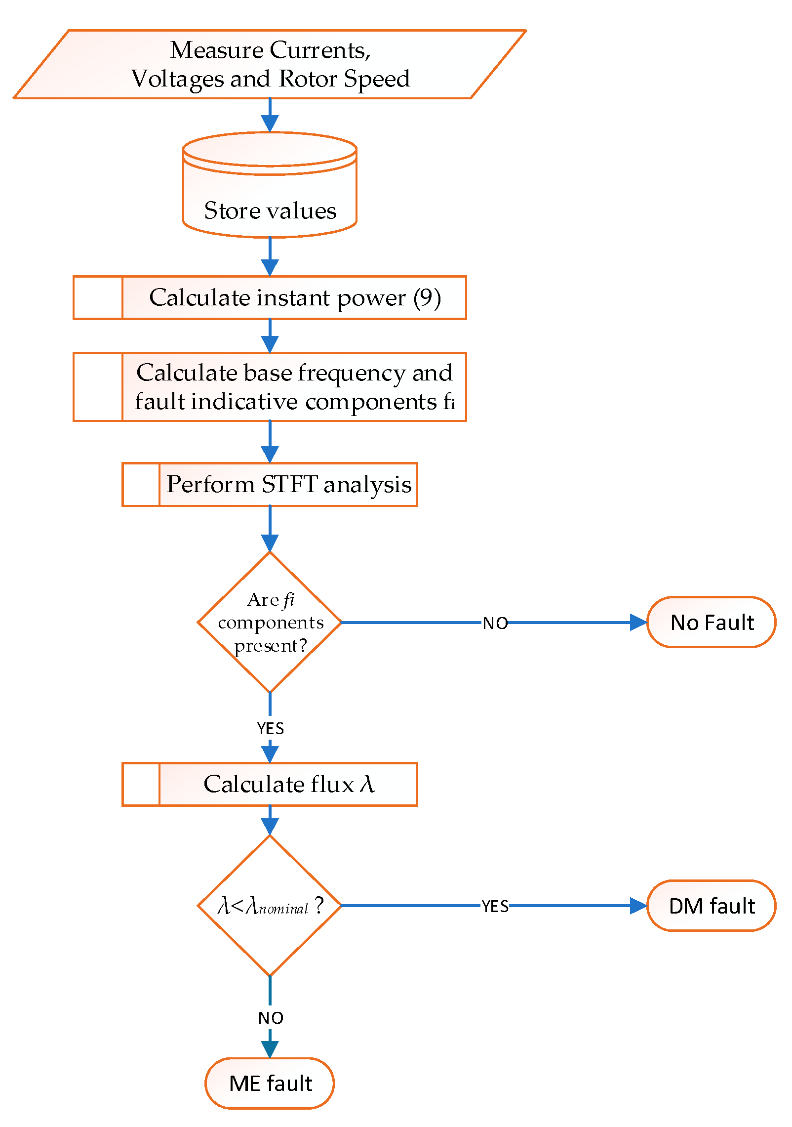
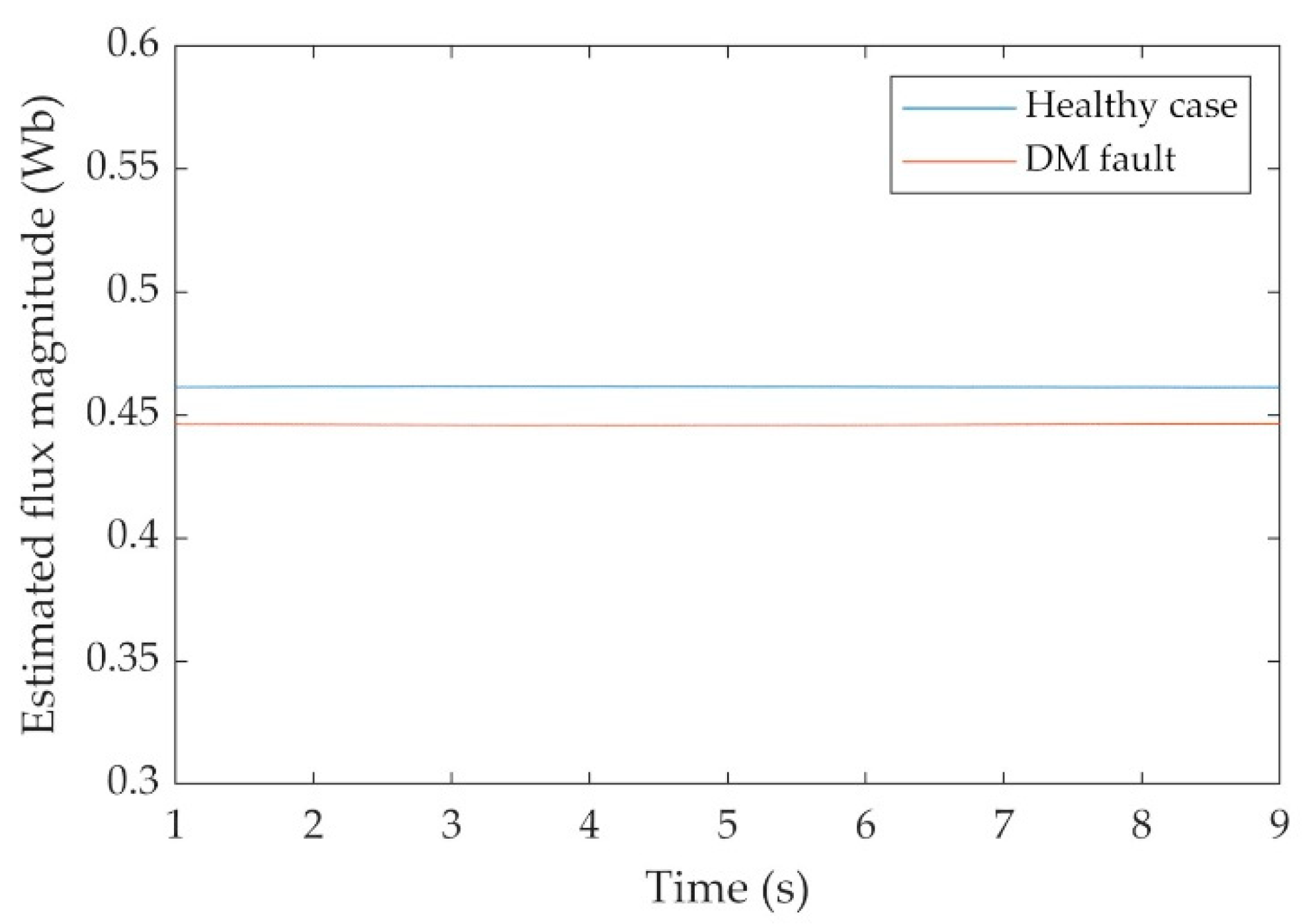
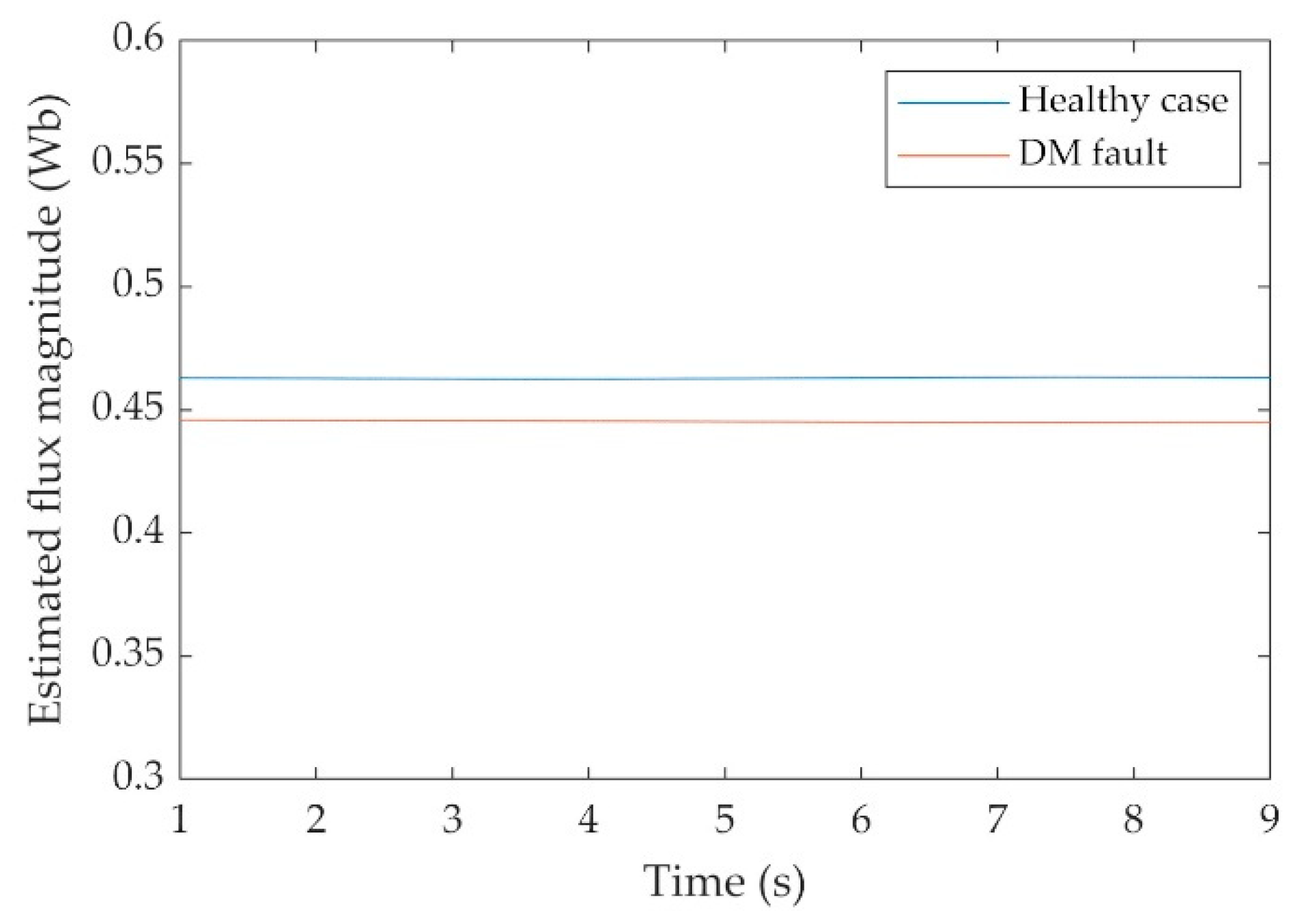
2.2. Detection of Demagnetization Faults Using the Instataneous Power

According to the analysis in the literature (e.g., [8]), in the presence of a demagnetization fault, harmonic frequencies ( 1 ± k p ) ω s t , where k = 1, 2, 3, … appear in the motor terminal quantities. So, the voltage in the terminals of the generator can be written in the presence of this fault as in Equation (7). The same frequencies are expected to appear in the terminal currents, expressed as in Equation (8):
V a b c = [ V a V b V c ] = [ V { cos ( ω s t + φ ) +   a v k cos [ ( 1 ± k p ) ω s t + φ v k ] } V { cos ( ω s t 2 π 3 + φ ) +   a v k cos [ ( 1 ± k p ) ω s t + φ v k 2 π 3 ] } V { cos ( ω s t + 2 π 3 + φ ) +   a v k cos [ ( 1 ± k p ) ω s t + φ v k + 2 π 3 ] } ]
Ι a b c = [ I a I b I c ] = [ Ι { cos ω s t +   a i k cos [ ( 1 ± k p ) ω s t + φ i k ] } Ι { cos ( ω s t 2 π 3 ) +   a i k cos [ ( 1 ± k p ) ω s t + φ i k 2 π 3 ] } Ι { cos ( ω s t + 2 π 3 ) +   a i k cos [ ( 1 ± k p ) ω s t + φ i k + 2 π 3 ] } ] ,
where ω s is the fundamental electrical frequency and a v i ,   a i i are the relative amplitudes of the voltage and current harmonics corresponding to the fault, respectively.
Multiplying with the Clarke transformation matrix, we have the voltage coordinates in a stationary reference frame, denoted with indexes α and β, as calculated from Equation (9):
V α β = 2 3 · [ 1 1 2 1 2 0 3 2 3 2 ] · [ V a V b V c ]
which results to Equation (10):
V α β = [ u α u β ] = [ V { cos ( ω s t + φ ) +   a v k cos [ ( 1 ± k p ) ω s t + φ v k ] } V { sin ( ω s t + φ ) +   a v k sin [ ( 1 ± k p ) ω s t + φ v k ] } ] ,
The current coordinates are extracted from (8) in a similar way:
I α β = [ i α i β ] = [ I { cos ω s t +   a i k cos [ ( 1 ± k p ) ω s t + φ i k ] } I { sin ω s t +   a i k sin [ ( 1 ± k p ) ω s t + φ i k ] } ] ,
The instantaneous power, as measured in the generator terminals is given by Equation (12):
P i = V a I a + V b I b + V c I c = u α i α + u β i β
Substituting values from (10), (11) to (12), results to Equation (10):
P i = V I { cos ( ω s t + φ ) +   α v k cos [ ( 1 ± k p ) ω s t + φ v k ] } · { cos ω s t +   α i k cos [ ( 1 ± k p ) ω s t + φ i k ] } + V I { sin ( ω s t + φ ) +   α v k sin [ ( 1 ± k p ) ω s t + φ v k ] } · { sin ω s t +   α i k sin [ ( 1 ± k p ) ω s t + φ i k ] }
As the coefficients αvkαik represent the amplitudes of the fault-indicative frequencies, it is well-known that each of them will be much lower that unit. So, we can safely make the approximation that αvkαik ≪ 1 and omit the products that include the expression, as their influence in the equation is negligible. This way, we conclude to Equation (14):
P i = V I { 1 +   A k c o s [ ( ± k p ) ω s t + φ k ] } ,
where:
A k = sign [ α v k cos φ v k + α i k cos ( φ i k φ ) ] α v k 2 + α i k 2 + 2 α v k α i k cos ( φ + φ v k φ i k )
φ k = tan 1 ( α v k sin φ v k + α i k sin ( φ i k φ ) α v k cos φ v k + α i k cos ( φ i k φ ) )
From (14), it is obvious that the fault-indicative frequencies are also present in the instant power signal, making it the ideal signal for the detection of the fault. The presence of these frequencies is indicative of the ME and DM faults, however they do not give sufficient information to discriminate between them. Therefore, a unique fault-indicative condition should be supplied.
In the case of a partial or total loss of a permanent magnet in the rotor, a decrease in the magnetic flux produced by the permanent magnets, as calculated using the machine equations, is expected. This decrease is not expected in the ME fault, as eccentricity causes the airgap to variate around a constant or rotating center, without affecting its average value.
To calculate the magnet-produced flux, a simplified algorithm is presented in this paper. Equations (1) and (2) can be written as:
d λ α ( t ) d t = u α ( t ) R S i α ( t ) d λ β ( t ) d t = u β ( t ) R S i β ( t )
Especially in the steady-state condition, electrical quantities in (17) are sinusoidal, so the components of λ can be given by Equations (18) and (19). Considering relatively slow transient conditions where the rotor speed, and therefore the electrical frequency, is subject to slow variations, deviations from the steady state are not expected to introduce critically high errors to the flux components estimation.
λ α ( t ) = u α ( t ) R S i α ( t ) p ω m
λ β ( t ) = u β ( t ) R S i β ( t ) p ω m
From the α-β components of the flux vector, the magnets’ flux magnitude can be calculated as:
λ m ( t ) = ( λ α ( t ) L s i α ( t ) ) 2 + ( λ β ( t ) L s i β ( t ) ) 2
One of the main conditions that the Clarke transformation should comply with, is that the machine must be symmetrical. It is straightforward that this condition should also be valid in (20). As demagnetization faults often introduce asymmetries, deviations are expected at the flux magnitude, which could be expressed as ripple and a reduced flux average value. The concept behind this work is to compare this average value of the flux with the respective value of the healthy machine to deduce the fault condition. For example, if one of the 32 magnets is lost, it can be estimated that the calculated average flux will decrease by a ratio of 1/32, which means 3% of its initial (healthy) value. In addition, for Equations (18) and (19) to be valid, it is essential the generator to operate at steady-state or quasi-steady-state condition. This can be assumed in our case, as it is expected that the wind generator will be operating with variating speed over time, however:
  • Speed variations are assumed to be slow compared to the electric quantities period;
  • Small deviations of the estimated flux from its actual value do not affect the proposed method.
However, to ensure the proposed strategy performance, the estimated flux value is filtered using a moving average filter with exponential forgetting. In addition, the filter has a variable forgetting factor, starting from a maximum value which decreases over time with a predefined factor to a minimum. This way, the filter can be reset when required (e.g., in a detected steady-state condition). The flow chart of the proposed methodology for DM fault detection is illustrated in Figure 1.

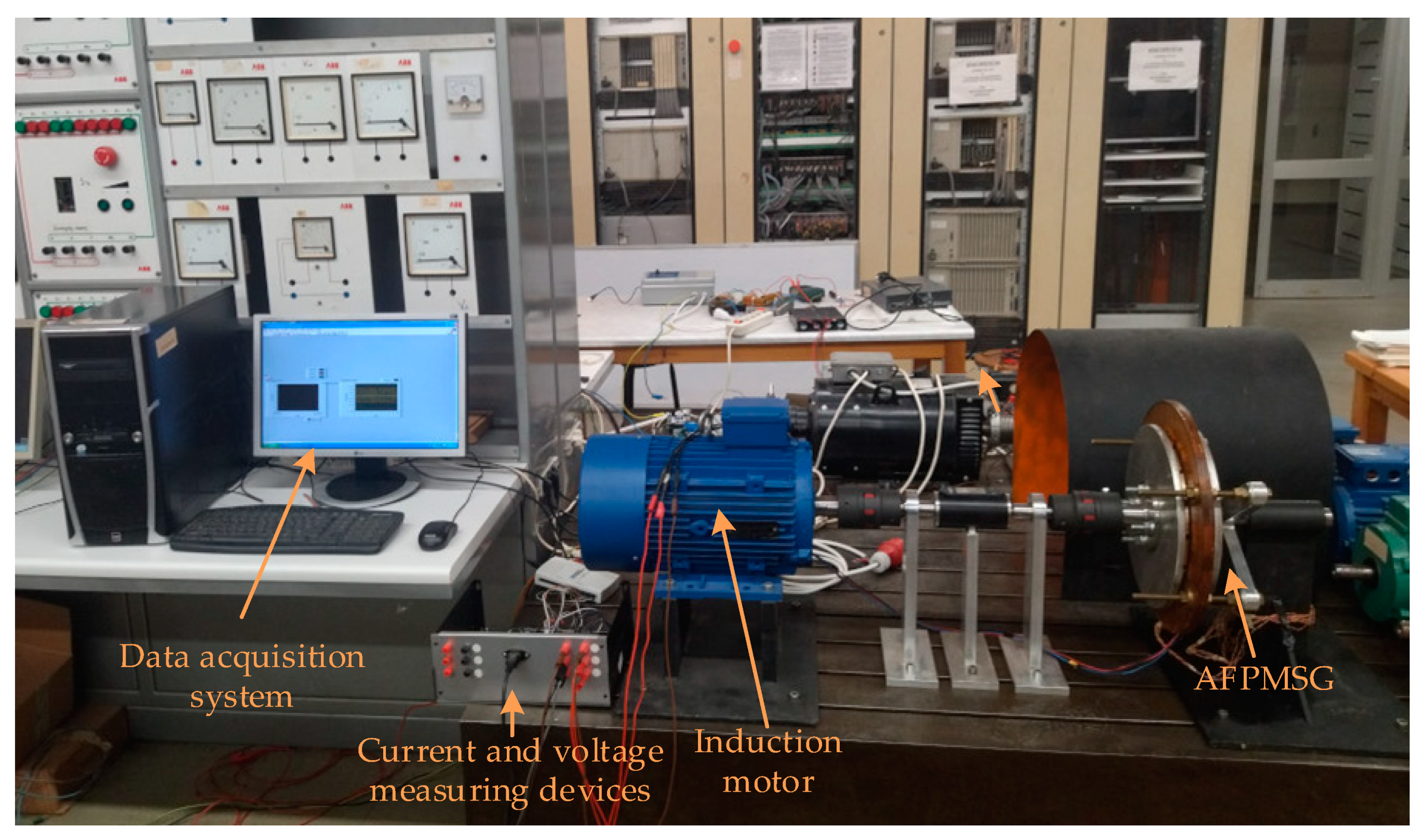
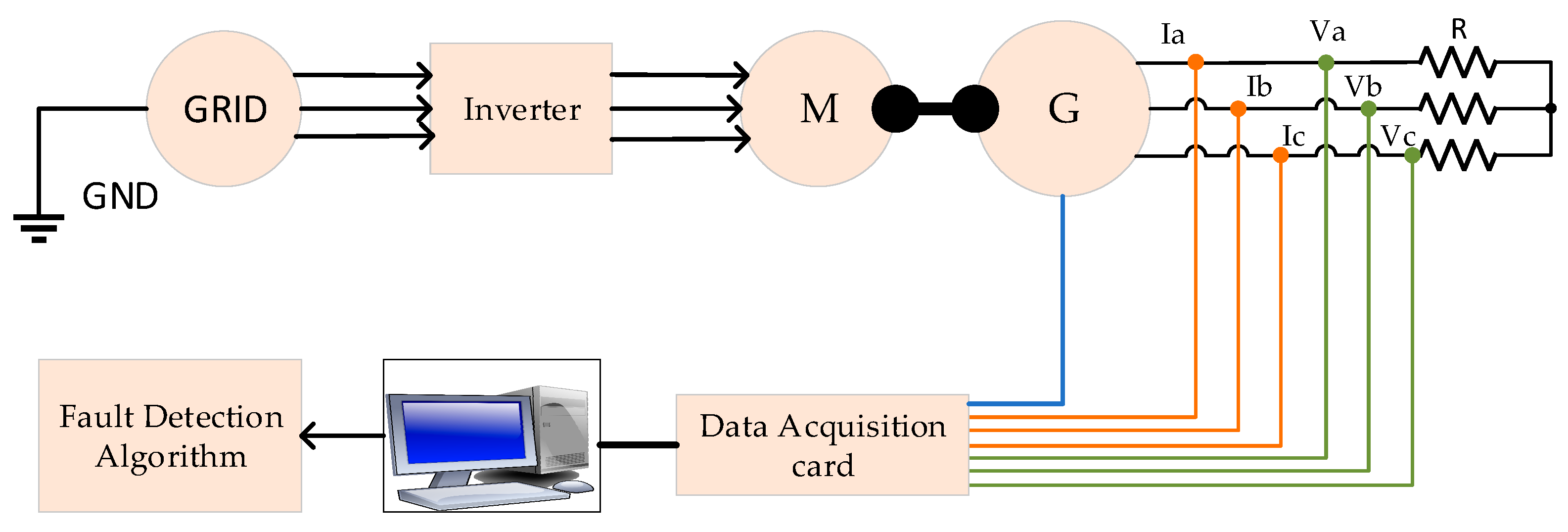
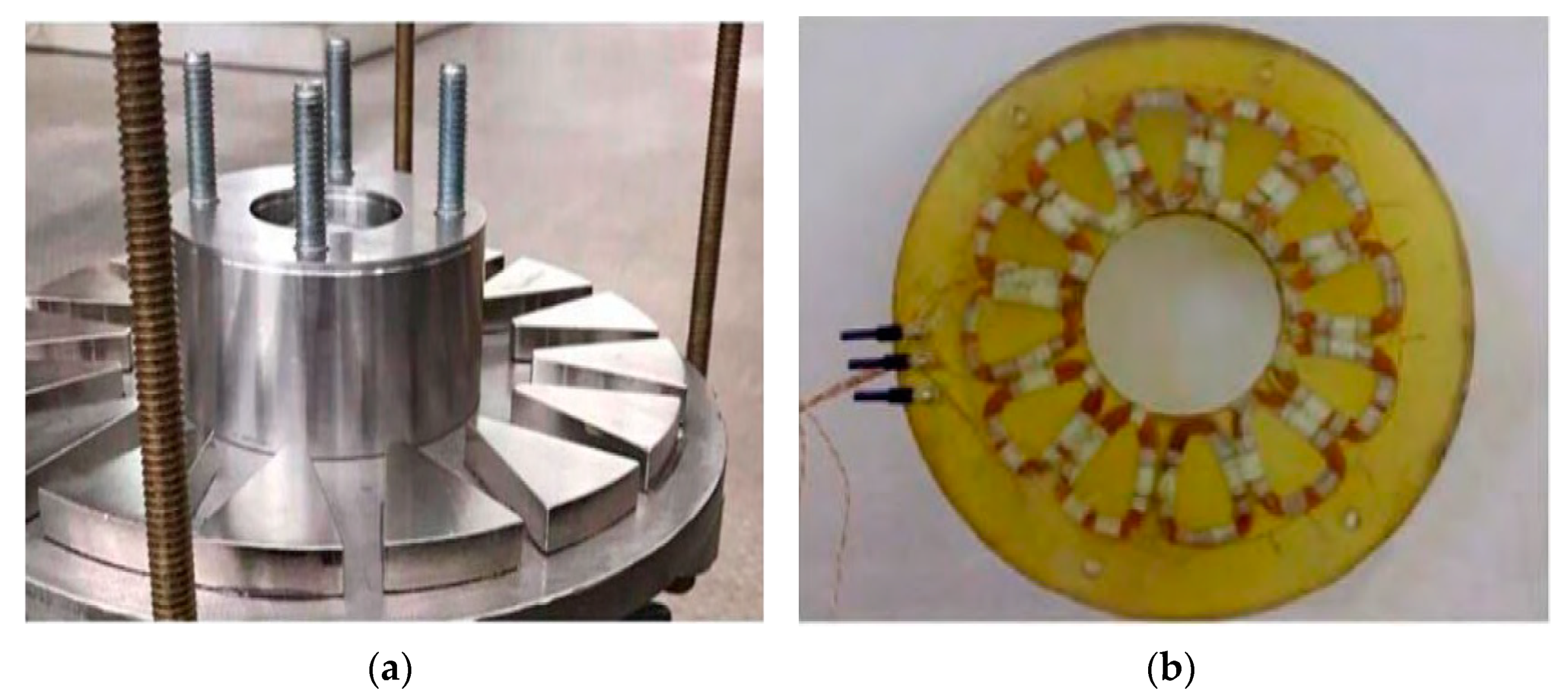
3. Experimental Setup

For the experimental investigation of the proposed technique, an Axial Flux Permanent Magnet Synchronous Generator (AFPMSG) is used. The machine has a double-sided rotor and one resin-embedded, coreless stator. Each rotor has 16 ΝdFeB magnets. Table 2 summarizes the most important of the generator parameters.
The AFPMSG is driven by a three-phase induction motor. Three current and three voltage hall-effect transducers were used to perform the stator voltages and currents measurement. Acquisition of the measurement values is performed using a LabView data acquisition card. The sampling frequency was set to 10 kHz. The measured data is collected in an ASCII file and the fault analysis is performed offline. To obtain the DM fault behavior without introducing eccentricity, one of the rotor magnets is removed and replaced by a part of equal weight.
In Figure 2. the laboratory test bench is shown, while in Figure 3. the block diagram of the whole test system structure is illustrated.
The synchronous generator was studied both in healthy situation and in demagnetization fault situation. The demagnetization fault was created by removing a magnet from one of the two rotors. One of the two rotors with the magnets and the stator of the machine are illustrated in Figure 4a,b respectively.

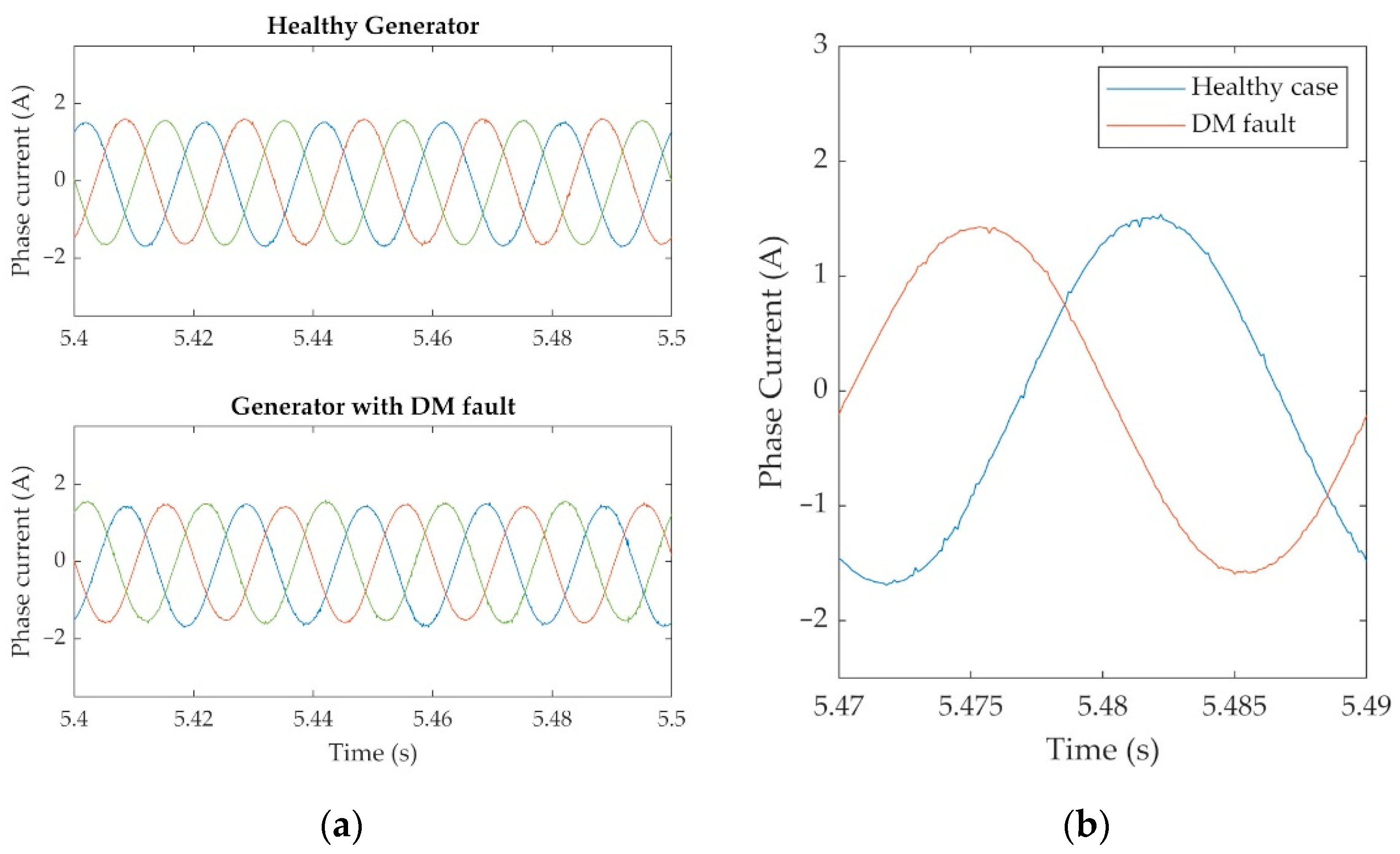
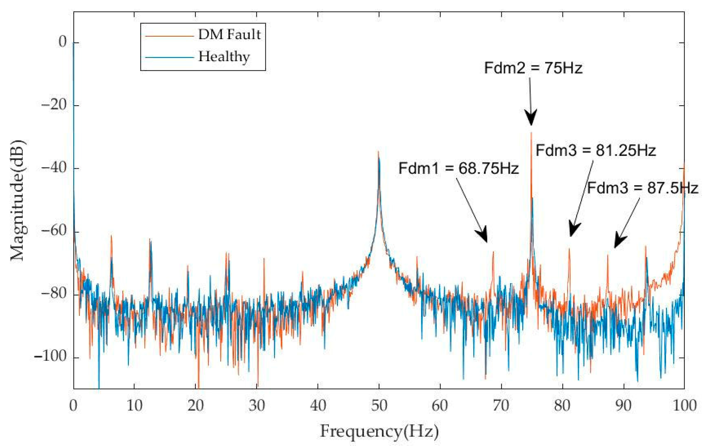
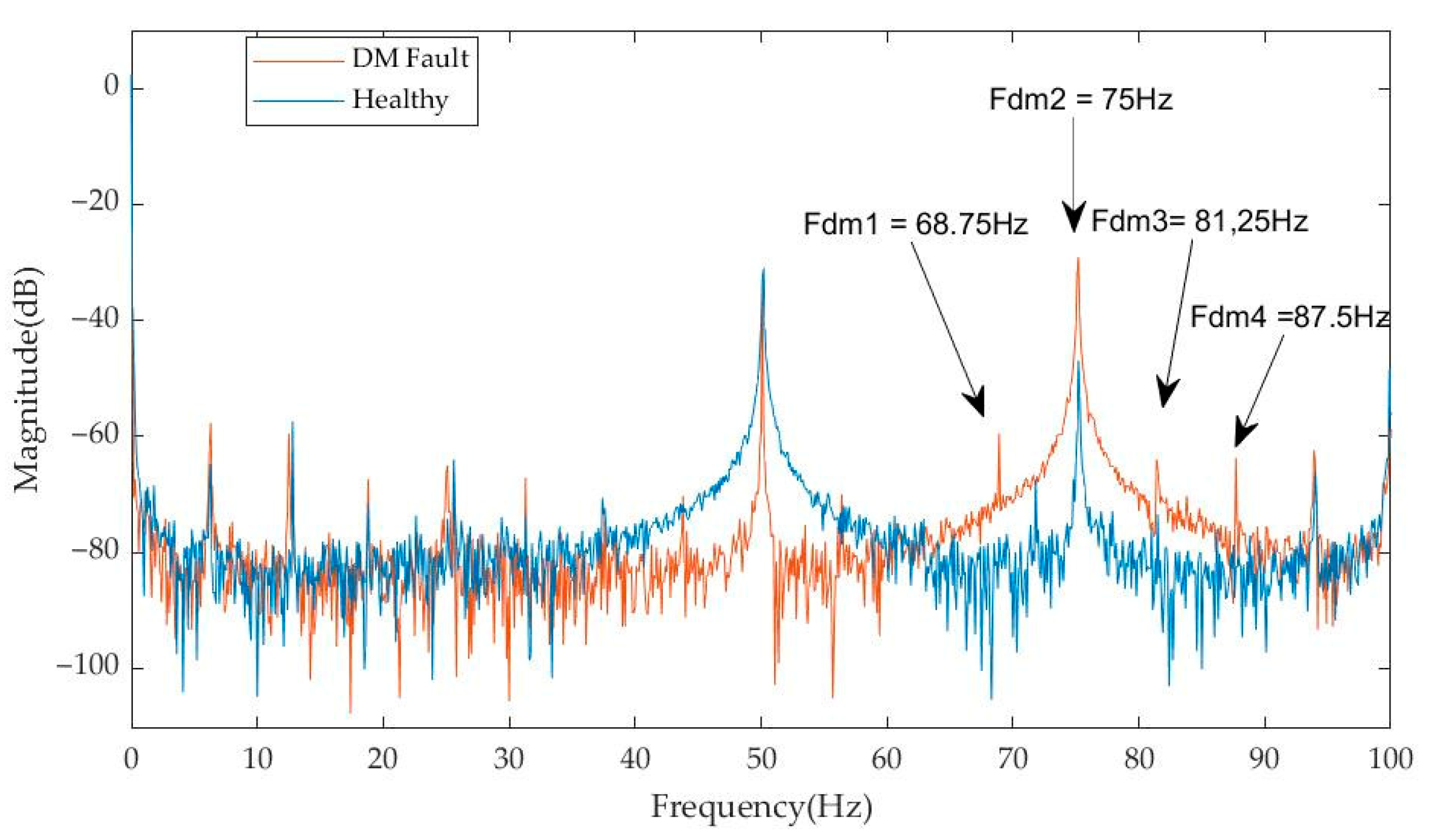
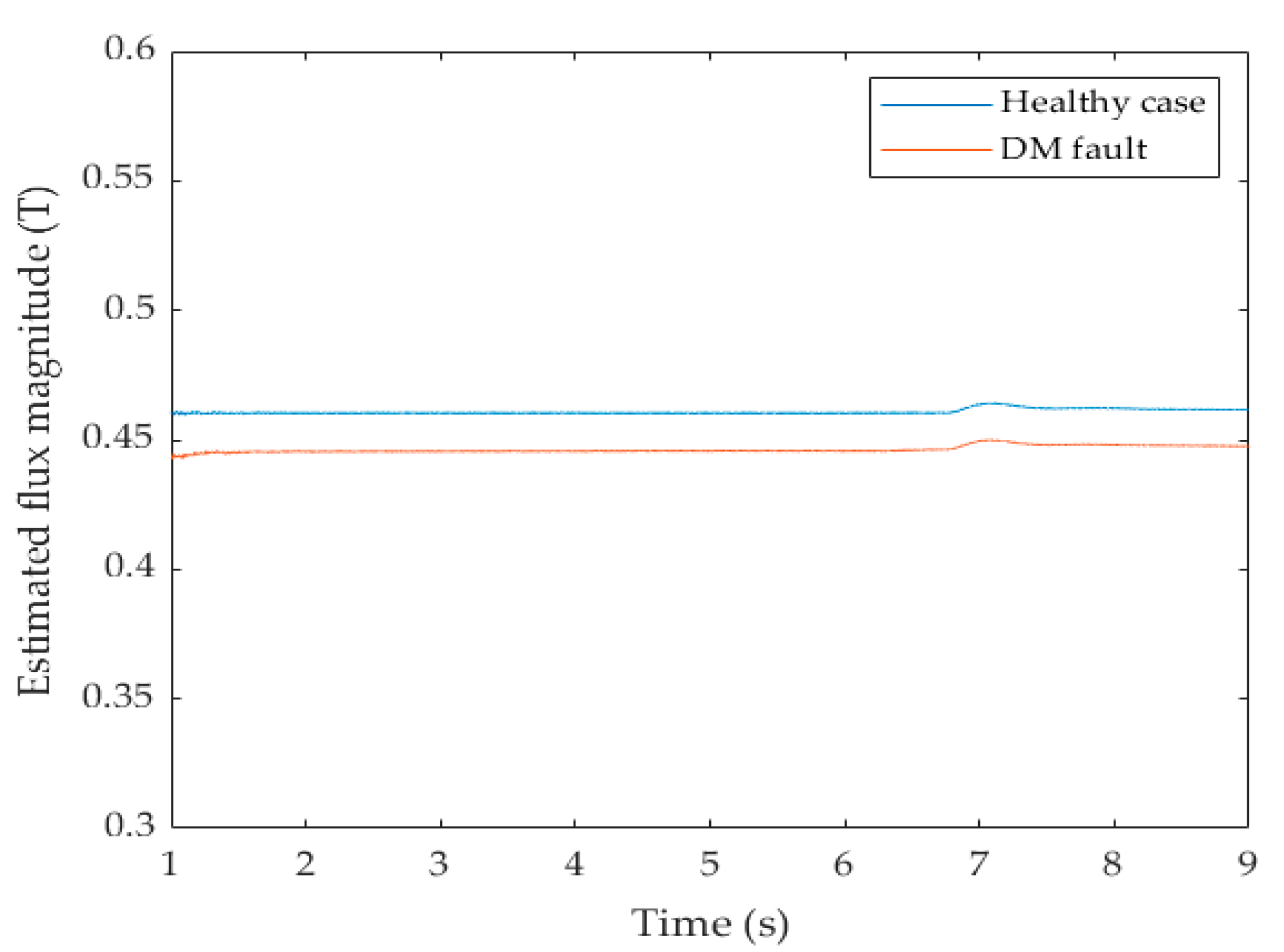
3.1. Operation under Steady-State Condition

To evaluate the operation of the proposed DM fault-detection methodology, various tests have been performed under different steady-state operating conditions, from which characteristic results are shown in Figure 5, Figure 6, Figure 7, Figure 8, Figure 9 and Figure 10. In these figures, the output voltage, estimated flux and power FFT are depicted under healthy and operations under fault for nominal voltage and frequency with a load of 225 W and 290 W, respectively, connected at the generator output. Multiple frequency components ( 11 f s p ,   12 f s p ,   13 f s p ,   14 f s p ) are chosen as fault-indicative to ensure reliability, considering the rule that if elevated magnitudes are detected at half or more of these frequencies, an error is signaled. The authors of this paper decided to choose these frequency components because it has been observed that their detection was easier under any operating condition at the laboratory experiments. The flux produced by the magnets in the healthy case is λ = 0.46Τ. If a level below 0.45 T is detected, a DM fault is signaled, otherwise the fault is considered as eccentricity. In this case, where a magnet is totally lost, it is also evident that the expected 3% decrease in the estimated flux value can be verified in both Figure 7 and Figure 10. More specifically, in Figure 6 and Figure 9, the instantaneous power frequency components (68.75 Hz, 75 Hz, 81.25 Hz, 87.5 Hz), produced for p = 8 and fs = 50 Hz, can be detected at the demagnetization case both for the load of 225 W and for the load of 290 W. In both cases, a significant increase in the amplitude of these frequencies is observed in the faulty case, as shown from the measured values in Table 3 and Table 4. More specifically, for a load of 225 W, it can be noticed that: at fDM1 = 68.75 Hz the power magnitude has changed from −81 dB (healthy machine) to −66.4 dB (demagnetized machine); at fDM2 = 75 Hz the magnitude has changed from −49.5 dB to −29.4 dB; at fDM3 = 81.25 Hz the magnitude has changed from −79.5 dB to −65 dB; and at fDM4 = 87.5 Hz the magnitude has changed from −81 dB to −67.3 dB. Respectively, for a load at 290 W, it can be noticed that: at fDM1 = 68.75 Hz the power magnitude has changed from −77 dB (healthy machine) to −59.5 dB(demagnetized machine); at fDM2 = 75 Hz the magnitude has changed from −47 dB to −29 dB; at fDM3 = 81.25 Hz the magnitude has changed from −73.5 dB to −65 dB; and at fDM4 = 87.5 Hz the magnitude has changed from −80 dB to −63.5 dB. In both cases, a detectable difference between the healthy and the faulty machine in the magnitude of these characteristic harmonics, combined with the estimated permanent magnet flux is providing a reliable means for the demagnetisation fault detection.
From the experimental results, it is obvious that by using both harmonics and flux criteria the DM fault can be reliably detected and discriminated from eccentricity faults. To obtain the frequency spectrum, FFT is adequate. However, in general, wind generators are not expected to operate in steady state, so STFT analysis should be used to extract the power spectra.

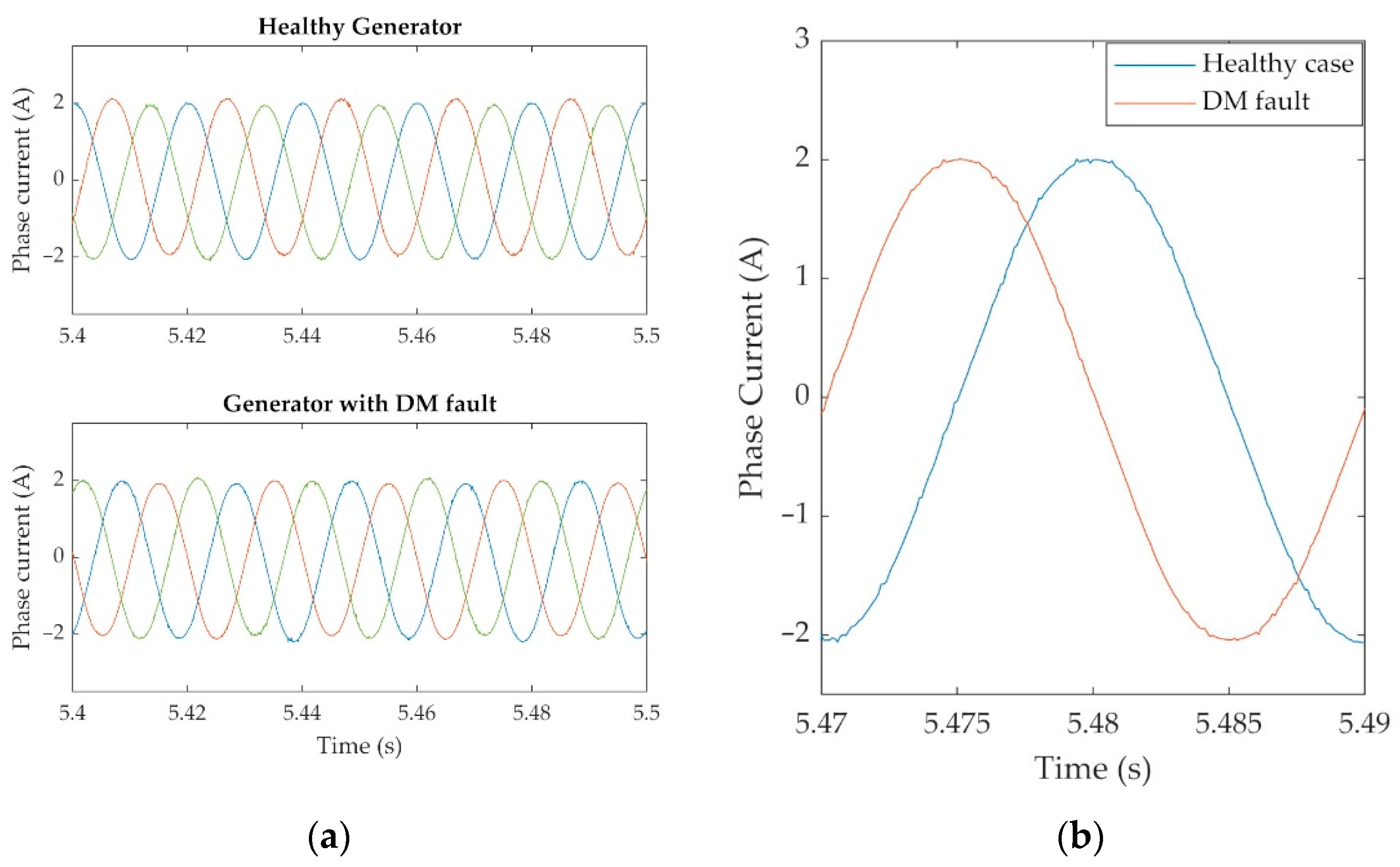
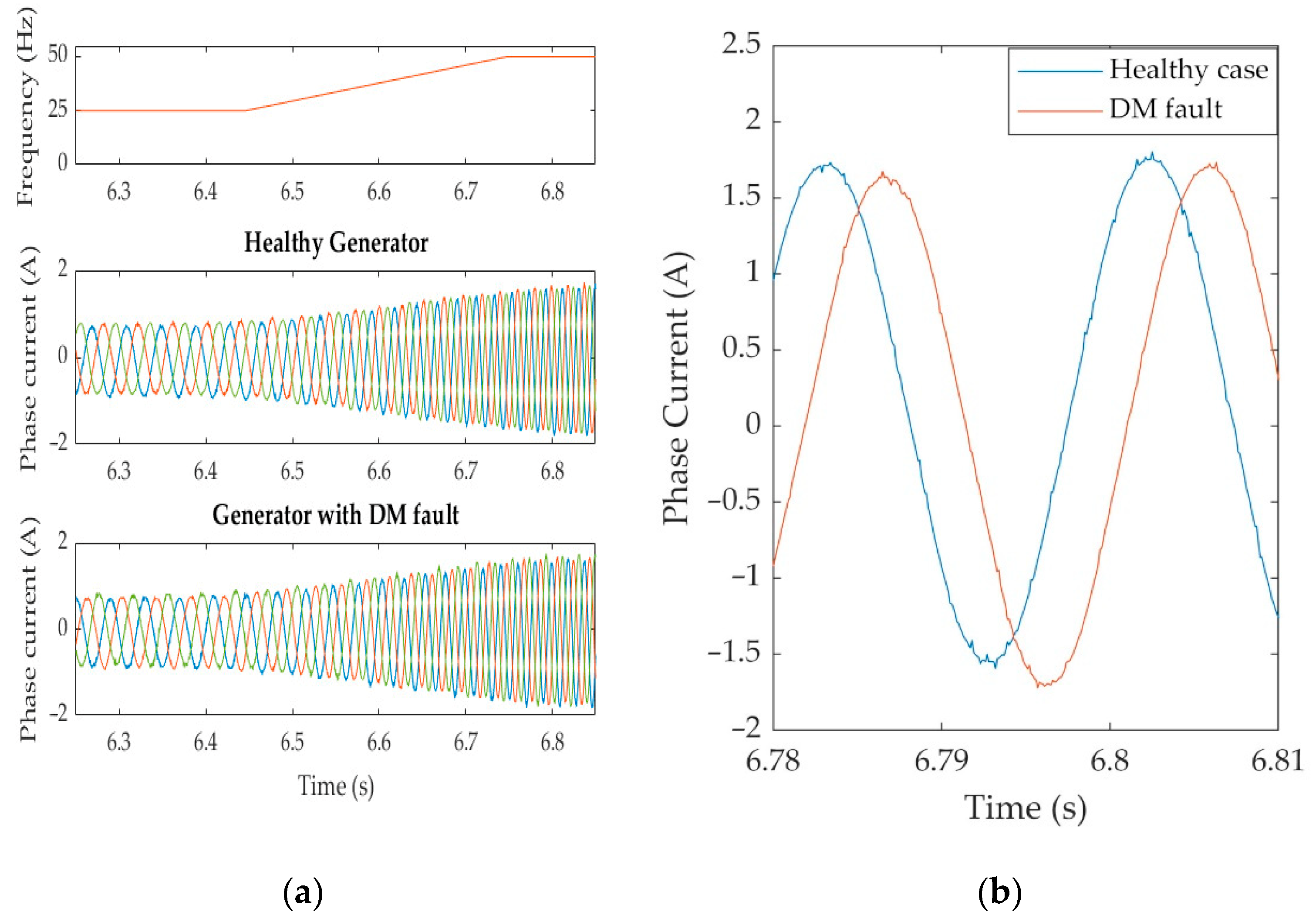
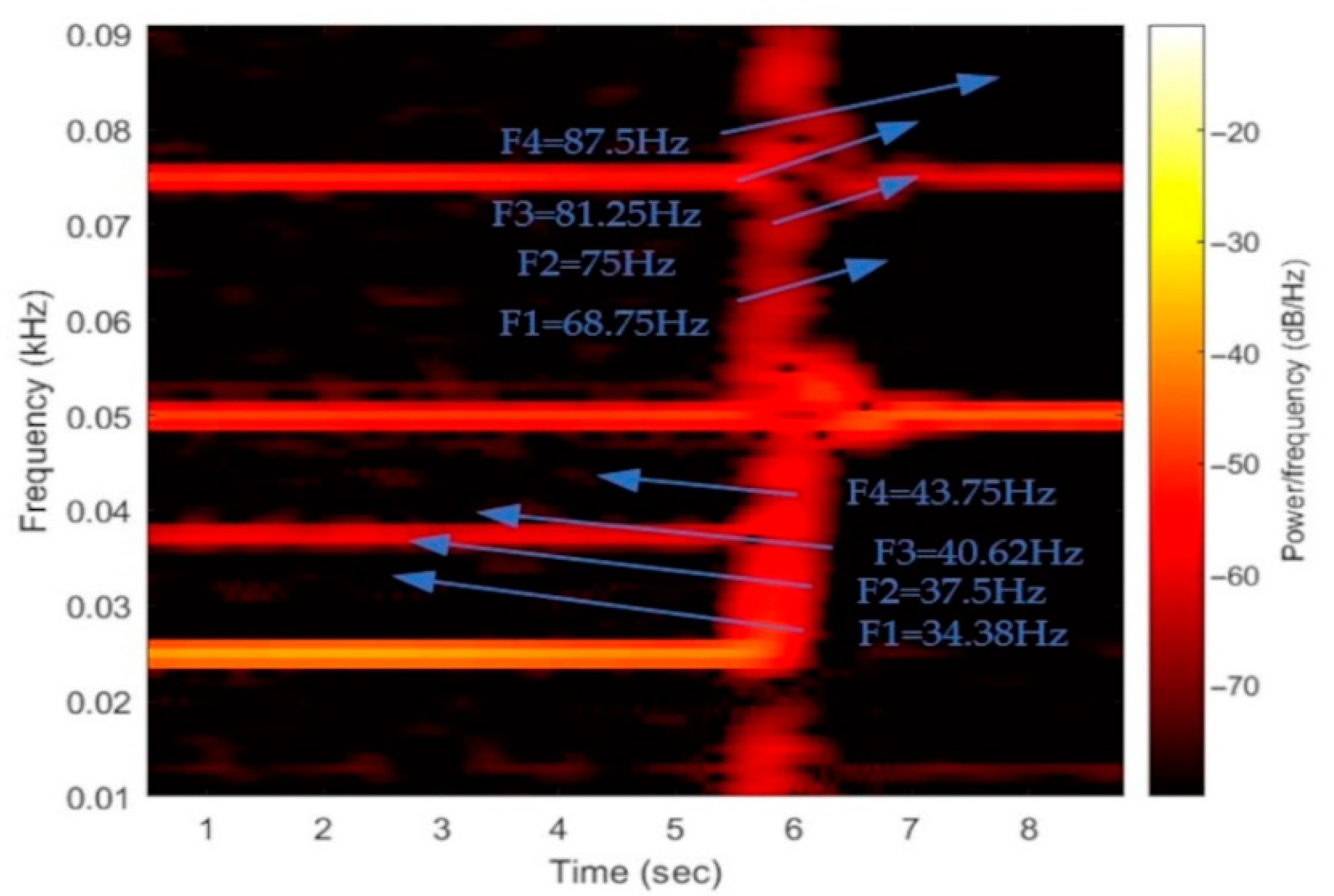
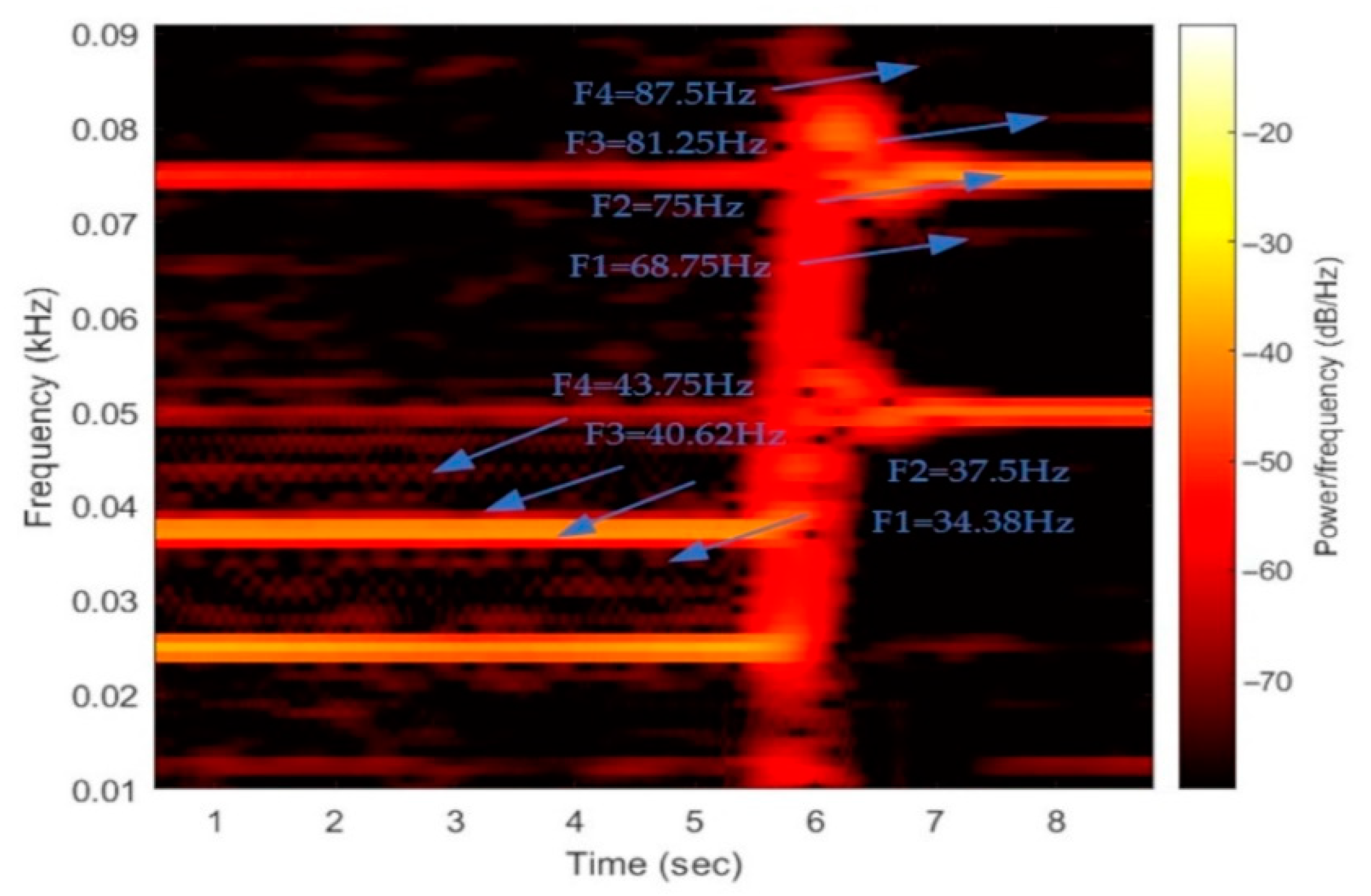
3.2. Transient Operation

Finally, experimental tests have been performed to test the validity of the proposed fault-detection methodology during transient operation of the generator. These tests included operation of the machine considering variable load and rotating speed. Hereafter, characteristic results from a fast speed change of the generator, when the rotor speed doubles within a time interval of 0.4 s. As the FFT algorithm fails to perform due to the variable frequency, STFT analysis is used, as described. Results shown in Figure 11, Figure 12, Figure 13 and Figure 14 prove that the fault can also be reliably detected at variable speed, combining the information obtained by the STFT and the flux estimation. More specifically, in Figure 11 the currents of the healthy and demagnetized machine are presented for a speed change. In Figure 12 and Figure 13, the results of the STFT algorithm are presented for both the healthy machine and the demagnetized case, respectively. The instantaneous power frequency components (34.38 Hz, 37.5 Hz, 40.62 Hz, 43.75 Hz), produced for fs = 25 Hz and k = 11, 12, 13, 14, can be detected at a time interval of 0–6 s at Figure 13 (demagnetized case), while they are not shown at Figure 12 (healthy). Additionally, when electrical frequency becomes 50 Hz at the time interval of about 6–10 s, it can be noticed that frequency components shift to the new values corresponding to fs = 50 Hz (68.75 Hz, 75 Hz, 81.25 Hz, 87.5 Hz) at Figure 13, while these components do not show in Figure 12. It is worthy to refer that the frequency component of 75 Hz is present both in the healthy and demagnetized case for fs = 50 Hz and the frequency component of 37.5 Hz for fs = 25 Hz, but with a bigger amplitude in the demagnetized machine. The arrows depict the four frequency components for operation frequencies fs = 25 Hz, 50 Hz both at healthy and demagnetization condition. In Figure 14, the estimated flux amplitude is presented for speed change from 25 Hz to 50 Hz.

4. Conclusions

A new methodology for detecting demagnetization faults in axial flux permanent magnet synchronous wind generators is presented in this study. Demagnetization faults occur when a partial or total loss of the magnetic properties of the permanent magnet material appears and could concern only one of the machine magnets or all of them. In particular, when it comes to signature analysis and the demagnetization fault affecting only part of the magnets, DM fault signatures are almost identical to the ones of ME faults, making discrimination between the two fault types very difficult.
The proposed methodology consists of the analysis of the instant power spectrum of the generator, combined with an estimator to derive the permanent magnet flux based on the machine equations. To this purpose, the fault indicative signatures contained in the power spectrum are analyzed. STFT is proposed as a method to derive the power spectrum, so that the method can perform during variations of the generator shaft speed. A permanent magnet flux estimator based on the machine model has been developed, to detect whether the fault indicative signatures reveal a DM or an eccentricity fault.
Experimental laboratory tests have been performed under a wide range of operating conditions and characteristic results are presented. Experimental results show that the proposed methodology is capable of detecting demagnetization faults and distinguish them from eccentricity ones under a wide variety of operating conditions.

Author Contributions

All authors contributed to this paper: investigation, methodology, software, validation, writing, E.M. and A.L.; project administration E.M.; writing—validation, review and editing, A.B. All authors have read and agreed to the published version of the manuscript.

Funding

This research received no external funding.

Institutional Review Board Statement

Not applicable.

Informed Consent Statement

Not applicable.

Data Availability Statement

Data sharing is not applicable to this article.

Acknowledgments

The authors would like to acknowledge the contributions of Joya Kappatou, G. Zalokostas and D. Spiratos for their work in designing and constructing the AFPMSG which has been used as the test machine in the experimental part.

Conflicts of Interest

The authors declare no conflict of interest.

References

  1. Chen, Y.; Liang, S.; Li, W.; Liang, H.; Wang, C. Faults and Diagnosis Methods of Permanent Magnet Synchronous Motors: A Review. Appl. Sci. 2019, 9, 2116. [Google Scholar] [CrossRef] [Green Version]
  2. Moosavi, S.S.; Djerdir, A.; Amirat, Y.A.; Khaburi, D.A. Demagnetization fault diagnosis in permanent magnet synchronous motors: A review of the state-of-the-art. J. Magn. Magn. Mater. 2015, 391, 203–212. [Google Scholar] [CrossRef]
  3. Urresty, J.C.; Riba, J.R.; Delgado, M.; Romeral, L. Detection of Demagnetization Faults in Surface-Mounted Permanent Magnet Synchronous Motors by Means of the Zero-Sequence Voltage Component. IEEE Trans. Energy Convers. 2012, 27, 42–51. [Google Scholar] [CrossRef]
  4. Gao, C.; Nie, Y.; Si, J.; Fu, Z.; Feng, H. Mode Recognition and Fault Positioning of Permanent Magnet Demagnetization for PMSM. Energies 2019, 12, 1644. [Google Scholar] [CrossRef] [Green Version]
  5. Haddad, R.Z.; Strangas, E.G. Fault Detection and Classification in Permanent Magnet Synchronous Machines using Fast Fourier Transform and Linear Discriminant Analysis. In Proceedings of the 2013 9th IEEE International Symposium on Diagnostics for Electric Machines, Power Electronics and Drives (SDEMPED), Valencia, Spain, 27–30 August 2013; pp. 99–104. [Google Scholar]
  6. Haddad, R.Z.; Strangas, E.G. On the Accuracy of Fault Detection and Separation in Permanent Magnet Synchronous Machines using MCSA/MVSA and LDA. IEEE Trans. Energy Convers. 2016, 31, 924–934. [Google Scholar] [CrossRef]
  7. Ruiz, J.R.; Rosero, J.A.; Espinosa, A.G.; Romeral, L. Detection of Demagnetization Faults in Permanent-Magnet Synchronous Motors Under Nonstationary Conditions. IEEE Trans. Magn. 2009, 45, 2961–2969. [Google Scholar] [CrossRef]
  8. Ebrahimi, B.M.; Roshtkhari, M.J.; Faiz, J.; Khatami, S.V. Advanced Eccentricity Fault Recognition in Permanent Magnet Synchronous Motors using Stator Current Signature Analysis. IEEE Trans. Ind. Electron. 2013, 61, 2041–2052. [Google Scholar] [CrossRef]
  9. Gliga, L.I.; Chafouk, H.; Popescu, D.; Lupu, C. Diagnosis of a Permanent Magnet Synchronous Generator using the Extended Kalman Filter and the Fast Fourier Transform. In Proceedings of the 2018 7th International Conference on Systems and Control (ICSC), Valencia, Spain, 24–26 October 2018; pp. 65–70. [Google Scholar]
  10. El Sayed, W.; Abd El Geliel, M.; Lotfy, A. Fault Diagnosis of PMSG Stator Inter-Turn Fault Using Extended Kalman Filter and Unscented Kalman Filter. Energies 2020, 13, 2972. [Google Scholar] [CrossRef]
  11. Rosero, J.; Romeral, L.; Ortega, J.A.; Urresty, J.C. Demagnetization Fault Detection by means of Hilbert Huang Transform of the stator current Decomposition in PMSM. In Proceedings of the 2008 IEEE International Symposium on Industrial Electronics, Cambridge, UK, 30 June–2 July 2008; Volume 68, pp. 310–324. [Google Scholar]
  12. Kao, I.H.; Wang, W.J.; Lai, Y.H.; Perng, J.W. Analysis of Permanent Magnet Synchronous Motor Fault Diagnosis Based on Learning. IEEE Trans. Instrum. Meas. 2019, 68, 310–324. [Google Scholar] [CrossRef]
  13. Moon, S.; Lee, J.; Jeong, H.; Kim, S.W. Demagnetization Fault Diagnosis of a PMSM Based on Structure Analysis of Motor Inductance. IEEE Trans. Ind. Electron. 2016, 63, 3795–3803. [Google Scholar] [CrossRef]
  14. Hong, J.; Park, S.; Hyun, D.; Kang, T.J.; Lee, S.B.; Kral, C.; Haumer, A. Detection and Classification of Rotor Demagnetization and Eccentricity Faults for PM Synchronous Motors. IEEE Trans. Ind. Appl. 2012, 48, 923–932. [Google Scholar] [CrossRef]
  15. Le Roux, W.; Harley, R.G.; Habetler, T.G. Detecting Rotor Faults in Low Power Permanent Magnet Synchronous Machines. IEEE Trans. Power Electron. 2007, 22, 322–328. [Google Scholar] [CrossRef]
  16. De Bisschop, J.; Vansompel, H.; Sergeant, P.; Dupre, L. Demagnetization Fault Detection in Axial Flux PM Machines by Using Sensing Coils and an Analytical Model. IEEE Trans. Magn. 2017, 53, 8203404. [Google Scholar] [CrossRef]
  17. De Bisschop, J.; Sergeant, P.; Hemeida, A.; Vansompel, H.; Dupré, L. Analytical Model for Combined Study of Magnet Demagnetization and Eccentricity Defects in Axial Flux Permanent Magnet Synchronous Machines. IEEE Trans. Mag. 2017, 53, 8107712. [Google Scholar] [CrossRef]
  18. Ajily, E.; Ardebili, M.; Abbaszadeh, K. Magnet defect and rotor eccentricity modeling in axial-flux permanent-magnet machines via 3-D Field Reconstruction Method. IEEE Trans. Ener. Conv. 2016, 31, 486–495. [Google Scholar] [CrossRef]
  19. Saavedra, H.; Riba, J.R.; Romeral, L. Magnet shape influence on the performance of AFPMM with demagnetization. In Proceedings of the IECON 2013-39th Annual Conference of the IEEE Industrial Electronics Society, Vienna, Austria, 10–13 November 2013; pp. 973–977. [Google Scholar]
  20. Bahador, N.; Darabi, A.; Hasanabadi, H. Demagnetization analysis of axial flux permanent magnet motor under three phase short circuit fault. In Proceedings of the 4th Annual International Power Electronics, Drive Systems and Technologies Conference, Tehran, Iran, 13–14 February 2013; pp. 333–337. [Google Scholar]
  21. Barmpatza, A.C.; Kappatou, J.C. Investigation of the combined eccentricity and demagnetization fault in an AFPMSG. In Proceedings of the 2020 International Conference on Electrical Machines (ICEM), Gothenburg, Sweden, 23–26 August 2020. [Google Scholar]
  22. Barmpatza, A.C.; Kappatou, J.C. Study of the demagnetization fault in an AFPM machine in relation with the magnet location. In Proceedings of the 2018 XIII International Conference on Electrical Machines (ICEM), Alexandroupoli, Greece, 3–6 September 2018. [Google Scholar]
  23. Barmpatza, A.C.; Kappatou, J.C. Study of a Combined Demagnetization and Eccentricity Fault in an AFPM Synchronous Generator. Energies 2020, 13, 5609. [Google Scholar] [CrossRef]
  24. Verkroost, L.; De Bisschop, J.; Vansompel, H.; De Belie, F.; Sergeant, P. Active Demagnetization Fault Compensation for Axial Flux Permanent-Magnet Synchronous Machines Using an Analytical Inverse Model. IEEE Trans. Ener. Conv. 2020, 35, 591–599. [Google Scholar] [CrossRef]
  25. Skarmoutsos, G.; Gyftakis, K.; Mueller, M. Detecting Partial Demagnetization in AFPM Generators by Monitoring Speed and EMF Induced in a Supplemental Winding. IEEE Trans. Ind. Infor. 2022, 18, 3295–3305. [Google Scholar] [CrossRef]
  26. Mínaz, M.R.; Akcan, E. An Effective Method for Detection of Demagnetization Fault in Axial Flux Coreless PMSG with Texture-Based Analysis. IEEE Access 2021, 9, 17438–17449. [Google Scholar] [CrossRef]
  27. Ioannis, P.T. Dynamic Analysis and Development of Diagnostic Methods for Controlled Motor System Consisting of a Slip Ring Asynchronous Machine and Power Electronic Converters. Doctoral Thesis, University of Patras, Patras, Greece, November 2007. [Google Scholar]
Figure 1. Flow chart of the proposed methodology for DM fault detection.
Energies 15 03220 g001
Figure 2. Laboratory setup used for the experimental tests.
Energies 15 03220 g002
Figure 3. Block diagram of the system structure.
Energies 15 03220 g003
Figure 4. (a) One of the two rotors with 16 permanent magnets, (b) the resin-immersed coils of the stator [2].
Energies 15 03220 g004
Figure 5. Experimental results: (a) three phase stator currents waveform for healthy generator and for DM fault, (b) focused stator currents waveform at healthy case (blue) and demagnetized case (red). (Generator operating under nominal voltage and frequency, with a load of 225 W.)
Energies 15 03220 g005
Figure 6. Experimental results: power spectrum for healthy generator and for DM fault (generator operating under nominal voltage and frequency, with a load of 225 W).
Energies 15 03220 g006
Figure 7. Experimental results: estimated flux magnitude for healthy generator and for DM fault (generator operating under nominal voltage and frequency, with a load of 225 W).
Energies 15 03220 g007
Figure 8. Experimental results: (a) three phase stator currents waveform for healthy generator and for DM fault,;(b) focused stator currents waveform at healthy case (blue) and demagnetized case (red). (Generator operating under nominal voltage and frequency, with a load of 290 W.)
Energies 15 03220 g008
Figure 9. Experimental results: power spectrum for healthy generator and for DM fault (generator operating under nominal voltage and frequency, with a load of 290 W).
Energies 15 03220 g009
Figure 10. Experimental results: estimated flux magnitude for healthy generator and for DM fault (generator operating under nominal voltage and frequency, with a load of 290 W).
Energies 15 03220 g010
Figure 11. (a) Experimental results: stator currents for healthy generator and for DM fault (frequency changes from 25 Hz to 50 Hz); (b) focused results for stator currents at healthy case (blue) and demagnetized case (red).
Energies 15 03220 g011
Figure 12. Power spectrum for healthy generator (frequency changes from 25 Hz to 50 Hz—examined fault indicative frequencies are shown with the blue arrows).
Energies 15 03220 g012
Figure 13. Power spectrum for DM fault (frequency changes from 25 Hz to 50 Hz—examined fault indicative frequencies are shown with the blue arrows).
Energies 15 03220 g013
Figure 14. Experimental results: Estimated flux magnitude for healthy generator and for DM fault (frequency changes from 25 Hz to 50 Hz).
Energies 15 03220 g014
Table 1. Fault types and the frequencies proposed for their detection.
Fault TypeIndicative Frequency
Inter-turn short circuit faults (ISC) f i s c = ( 2 k + 1 ) f s , (k = 1, 2, 3, …)
Mixed eccentricity (ME) f m e = ( 1 ± k p ) f s , (k = 1, 2, 3, …)
Demagnetization of the rotor (DM) f d m = ( 1 ± k p ) f s , (k = 1, 2, 3, …)
Table 2. Parameters of the double-rotor PMSG under study.
ParameterValue
Nominal Power350 W
Nominal Voltage80 V
Nominal frequency (fs)50 Hz
Nominal speed (ns)375 rpm
Number of poles for each rotor16
Stator Phase Resistance5.89 Ohm
Stator Phase Inductance17 mH
Table 3. Experimental results: instantaneous power frequency components at 225 W load.
Number of Harmonicf(Hz)Healthy Machine
(dB)
Demagnetized Machine
(dB)
(11 fs/p)68.75−81.0−66.4
(12 fs/p)75.00−49.5−28.4
(13 fs/p)81.25−79.5−65.0
(14 fs/p)87.50−81.0−67.3
Table 4. Experimental results: instantaneous power frequency components at 290 W load.
Number of Harmonicf(Hz)Healthy Machine
(dB)
Demagnetized Machine
(dB)
(11 fs/p)68.75−77.0−59.5
(12 fs/p)75.00−47.0−29.0
(13 fs/p)81.25−73.5−65.0
(14 fs/p)87.50−80.0−63.8
Publisher’s Note: MDPI stays neutral with regard to jurisdictional claims in published maps and institutional affiliations.

