Article

Consensus-Based Distributed Secondary Frequency Control Method for AC Microgrid Using ADRC Technique

1
College of Information and Electronic Engineering, Hunan City University, Yiyang 413000, China
2
College of Electronic Information and Electrical Engineering, Changsha University, Changsha 410000, China
*
Author to whom correspondence should be addressed.
Energies 2022, 15(9), 3184; https://doi.org/10.3390/en15093184
Submission received: 29 July 2021 / Revised: 10 October 2021 / Accepted: 17 March 2022 / Published: 27 April 2022

Abstract

:
To ensure safe and reliable operation, the ability to ride through various disturbances is vital for a microgrid with multi-inverters. As the voltage and frequency support comes from the power-electronic-based inverters, it is necessary to find a proper control strategy to improve the rejection ability of the DG inverter against disturbances. In this regard, this paper proposes a new distributed secondary frequency control approach for islanded microgrids, in which the main purpose is to remove the frequency deviation under droop control method with better disturbance rejection performance. Unlike many traditional approaches which rely on a detailed control model, the proposed one needs little model information thanks to the model-independent characteristic of active disturbance rejection control (ADRC) technique. A linear extended state observer is introduced to estimate the useless model dynamics (including unknown disturbances, unmodeled dynamics and nonlinear dynamics) which are then compensated in the control input. After the active compensation procedure, the nonlinear frequency control model can be converted into a quasi-linear model, based on which a proportional distributed control algorithm is established to restore the frequency and equalize the active power among the DGs. Simulation results based on a four-inverter-based microgrid show that the proposed approach achieves frequency restoration, active power sharing, as well as satisfactory disturbance rejection performance.

1. Introduction

With the rapid development of industry and technology, there is a growing demand for electricity, which leads to a considerable increase in energy consumption. As the renewable energy is environmentally friendly, the development of renewable energy has become a hot topic in order to cope with the energy crisis [1,2,3]. Unlike fossil energy, it is difficult to utilize renewable energy in a centralized way because renewable energy is usually geographically dispersed. Therefore, distribution generation has become an effective way to utilize these energy resources [4,5].
As an important part of smart grid, a microgrid is a small-scaled power generation and distribution system to integrated renewable energy, which is composed of distributed generations (DGs), energy storage equipment, loads and other equipment [6,7]. A microgrid can work in grid-connected operation mode and islanded operation mode. At the normal operation of power grid, the microgrid works in grid-connected operation mode, and the voltage and frequency regulation of the microgrid depends on the power grid [8]. When the power grid goes through unexpected fault, the static switch will automatically act to disconnect the microgrid from the power grid, which means that microgrid enters the islanded operation mode. In this occasion, the DGs in the microgrid are responsible for maintaining the islanded system’s operation as the support from power grid is unavailable [9].
Most DGs are connected to the microgrid through power-electronic-based inverters. The control algorithm of the DG inverter is determined by the operation state of the microgrid. In grid-connected operation mode, the main task for DGs is to deliver maximum power to power grid and the most commonly used control algorithm of DG inverter is constant power control [10]. In islanded operation mode, the voltage and frequency regulation tasks are taken by the DG inverters and the droop control algorithm is adopted for DG inverter often [11,12]. However, the traditional droop control algorithm cannot restore frequency and voltage to the rated values as voltage and frequency deviation is necessary for the communication-free decentralized control, which is an important characteristic of droop control strategy.
In order to compensate the deviation of voltage and frequency, secondary control strategy is proposed and applied to the microgrid. In the development of secondary control for the microgrid, centralized control and distributed control are two typical ways. The traditional centralized control method employs a microgrid central controller (MGCC) to obtain global information, and then provides control commands to the bottom control layer after optimization decision, which is featured with global awareness [13]. However, centralized control has disadvantages, such as heavy computation and communication burden, poor robustness, poor scalability and poor reliability. Different from centralized control, distributed secondary control obviates expensive communication network, which is very suitable to solve the problem of voltage and frequency restoration. A distributed control architecture of the microgrid is based on multi-agent theory, where each DG is regarded as an intelligent agent, and the whole microgrid is regarded as a multi-agent system. In the distributed control architecture, each DG only needs to exchange information with its adjacent DG to achieve the control goal. Hence, the communication network is sparse, and it can effectively avoid single point of failure and has high reliability [14]. In addition, a distributed secondary control is also featured with excellent characteristic of “plug and play” capability.
The distributed secondary voltage and frequency control is widely studied due to its notable advantages. In [15], the issue of frequency and voltage regulation in the secondary control of the microgrid is transformed into the problem of multi-agent system tracking synchronization through the feedback linearization method, which realizes the frequency and voltage regulation and the proportional distribution of active power. The inner states and system parameters are needed to facilitate a good linearization compensation performance, which is rather challenging in real conditions. The frequency and voltage recovery control based on a multi-agent consensus algorithm is proposed in [16], but the influence of line impedance mismatch on voltage recovery is not well solved. Additionally, the frequency control model is simplified into droop equation. Reference [17] presents a finite-time distributed robust secondary controller for an islanded AC microgrid, which enables the microgrid to restore the frequency to its reference value robustly in finite time against interference while maintaining good real power sharing accuracy. However, active power information is required to be shared with the adjacent DG units, at the cost of privacy leakage to some degree. A linearized distributed finite-time control protocol based on feedback mechanism is proposed in [18], which realizes frequency and voltage restoration as well as reasonable power allocation, and improves the convergence rate and anti-interference ability of the system. The authors of [19,20] propose economic dispatch methods based on discrete consistent algorithm for intelligent distribution network, and solve the problem of frequency autonomy and cooperative control of isolated intelligent distribution network, whereas it does not deal with the issue of frequency recovery. In [21,22,23,24], a distributed secondary optimization control method based on reinforcement learning is proposed to meet the requirements of frequency recovery and voltage regulation of microgrids. However, the intelligent algorithm-based distributed secondary control may need a great deal of training data, which complicates the controller design. In [25,26], communication delay is focused on the design process of distributed secondary controller for the microgrid, while the rejection ability to model disturbance is not paid much attention. A secondary distributed frequency and volage controller considering equal generation cost increment and reactive power sharing is proposed in [27]. The generation cost increment values from different DGs are exchanged and privacy is still compromised to some extent. In a microgrid with time-varying load disturbance and large time delay, the robust frequency recovery capability is of great important for DGs. To this point, a finite-time robust distributed cooperative secondary control protocol is proposed in [28] by only regulating the active power output of each DG unit. Although active power sharing as well as frequency recovery are realized simultaneously, the robustness of the control protocol to communication failure can be further explored.
In fact, many previous studies design the distributed secondary voltage and frequency control algorithms ignoring the model nonlinearity and disturbance in the control system or requiring detailed model information for feedback linearization. However, a microgrid is a complicated nonlinear system with strong coupling characteristic between the voltage and frequency control and unknown disturbances [29,30]. In [31], a terminal sliding mode control has been used locally for each DG unit to deal with modeling errors, disturbances and parametric uncertainties in the microgrid. Similarly, slide mode control algorithm has been employed in [32] to significantly improve the robustness of distributed secondary voltage and frequency controller against to model uncertainties and disturbance. These advanced controllers are effective in robustness enhancement; however, the controller construction is complicated. Looking for a concisely designed distributed secondary controller which also features good disturbance rejection capability for the microgrid is still in demand.
ADRC technique is proposed with an impressive disturbance rejection ability, while having a rather simply control design process [33,34]. The kernel inside ADRC technique is to reconstruct the control objective into a standardized model based on input-output feedback linearization with the help of an extended state observer. Thanks to its superiority, an ADRC-based distributed secondary frequency control approach is proposed considering the nonlinearity and unmodeled dynamics (high-order term derived from time delay, PWM modulation, etc.) in the frequency control system. This model nonlinearity and unmodeled dynamics are uniformly regarded as a model disturbance. Then, the model disturbance is compensated using the extended state observer [35]. Based on the compensated model, the frequency restoration and power sharing are realized with proportion-based control law. The main contributions of the proposed work are summarized as follows:
(1) The active power sharing is successfully achieved among the DGs via equalizing the control input of the secondary frequency controller. As a consequence, the active power information of DGs is not traded between each other. In this manner, the privacy of individual unit can be well protected.
(2) Nonlinearities, uncertainties and disturbances in the frequency control system are regarded as a lumped model disturbance, which is then estimated as a new state using an extended state observer. This undesired model disturbance is directly compensated in the control input. As a result, the initial nonlinear frequency control model can be transformed into a quasi-linear first order model, based on which a control algorithm can be easily and effectively established.
(3) Using ADRC technique, the secondary frequency regulation performance is effectively improved with better disturbance rejection ability and smoother frequency regulation performance.
The rest of this paper is organized as follows: The principle of droop control and frequency dynamic modelling is firstly introduced in Section 2. The ADRC-based distributed secondary frequency control approach is proposed in Section 3. Section 4 presents some case studies to verifies the feasibility and effectiveness of the proposed method. Section 5 concludes the paper.

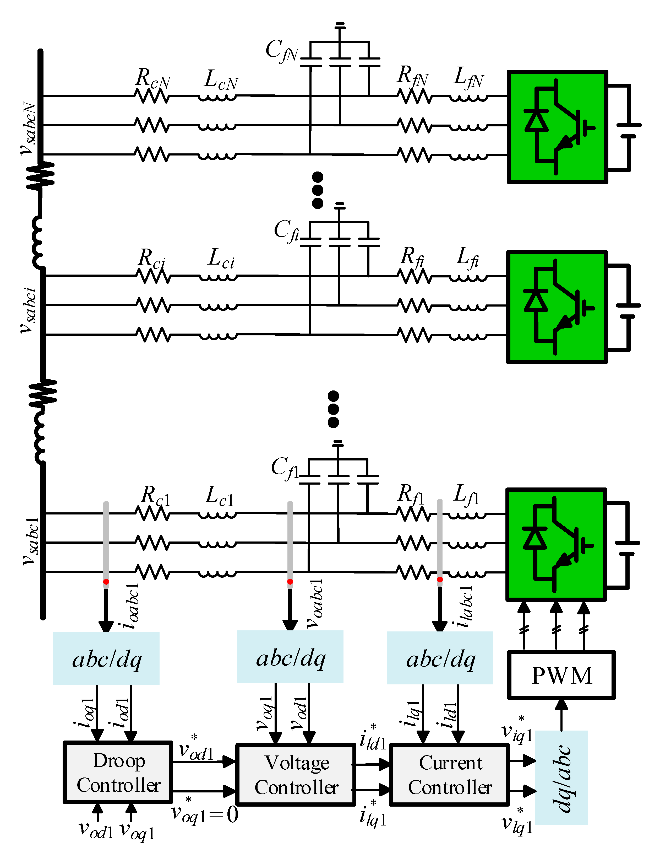
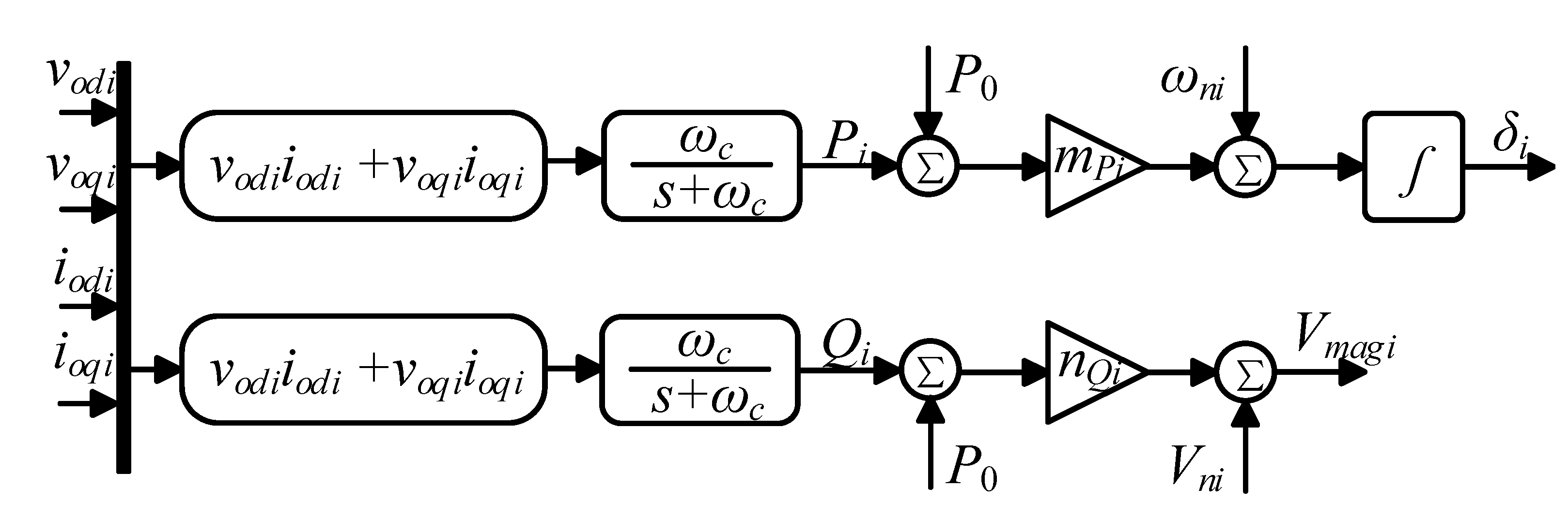
2. Droop Control and Frequency Control System Modelling

A block diagram of a DG inverter, with the primary control loops including the droop, the voltage and the current loops, is shown in Figure 1. The DG #i is connected to the microgrid through a transmission line. The dynamic model is formulated in the d-q reference frame. To show the principle of droop control, the phasor expressions of output voltage voabci and terminal voltage vsabci in Figure 1 are assumed as Voi ∠ 0 and VSi ∠ −δi, respectively. The power flow from the DG #i to the microgrid can be expressed by
{ P ^ i = V O i R c i 2 + X c i 2 [ R c i ( V O i V S cos δ i ) + X c i V S i sin δ i ] Q ^ i = V O i R c i 2 + X c i 2 [ R c i V S i sin δ i + X c i ( V O i V S i cos δ i ) ]
where P ^ i and Q ^ i is the measured active and reactive power of DG #i.
Assuming a dominantly inductive transmission line (Xci >> Rci) and a very small power angle leads to the following approximation [36]:
{ δ i X c i P ^ i V O i V S i V O i V S i X c i Q ^ i V O i
The main task of DGs in an islanded microgrid is to support voltage and frequency regulation. As the over-current capability of IGBT is strictly limited, power equalization among the DG inverters should be carefully considered. Droop control entitles the DG inverter with output characteristic of synchronous generator and thus can realize voltage and frequency regulation as well as power sharing. The overall diagram of primary control is presented in Figure 1, which consists of a droop controller, inner voltage and current controller. Detailed control diagram of droop control is shown in Figure 2. As it can be seen, the voltage magnitude and phase angle references are derived through the power derivation. The DC components of the instantaneous active and reactive power terms are purified by a low-pass filter with cut-off frequency ωc, which can also be expressed by
{ P ˙ i = ω c P i + ω c ( v o d i i o d i + v o q i i o q i ) Q ˙ i = ω c Q i + ω c ( v o q i i o d i v o d i i o q i )
where ωc is the bandwidth of low-pass filter which is set to filter high frequency noise except for DC component in the measured power. Pi and Qi are the filtered active power and reactive power, respectively.
As the droop control is expected to stabilize the microgrid and realize a proportional load sharing among the DGs [37], it forms a linearized droop characteristic given by
{ ω i * = ω n i m P i ( P i P 0 ) V m a g i * = V n i n Q i ( Q i Q 0 )
where ω i * is the angular frequency reference, V m a g i * is the voltage magnitude reference, mPi, nQi are the active and reactive power droop coefficients, P0 and Q0 are the rated set points of active and reactive power.
With the output characteristics of DGs regulated based on (4), a decentralized control manner is realized since the DGs only need to measure power at their local sides. However, frequency and voltage derivations occur, which need to be further restored.
Combining (3) with (4) and ignoring the dynamics of inner double loops yields:
ω ˙ i = ω c ω n i + ω ˙ n i ω c ω i + m p i ω c ( P 0 v o d i i o d i v o q i i o q i )
It is easy to observe that (5) is nonlinear, which makes the secondary frequency control design difficult. Based on the derived nonlinear frequency control model in (5), the distributed secondary frequency controller design will be discussed in the following section.

3. Proposed Distributed Secondary Frequency Control

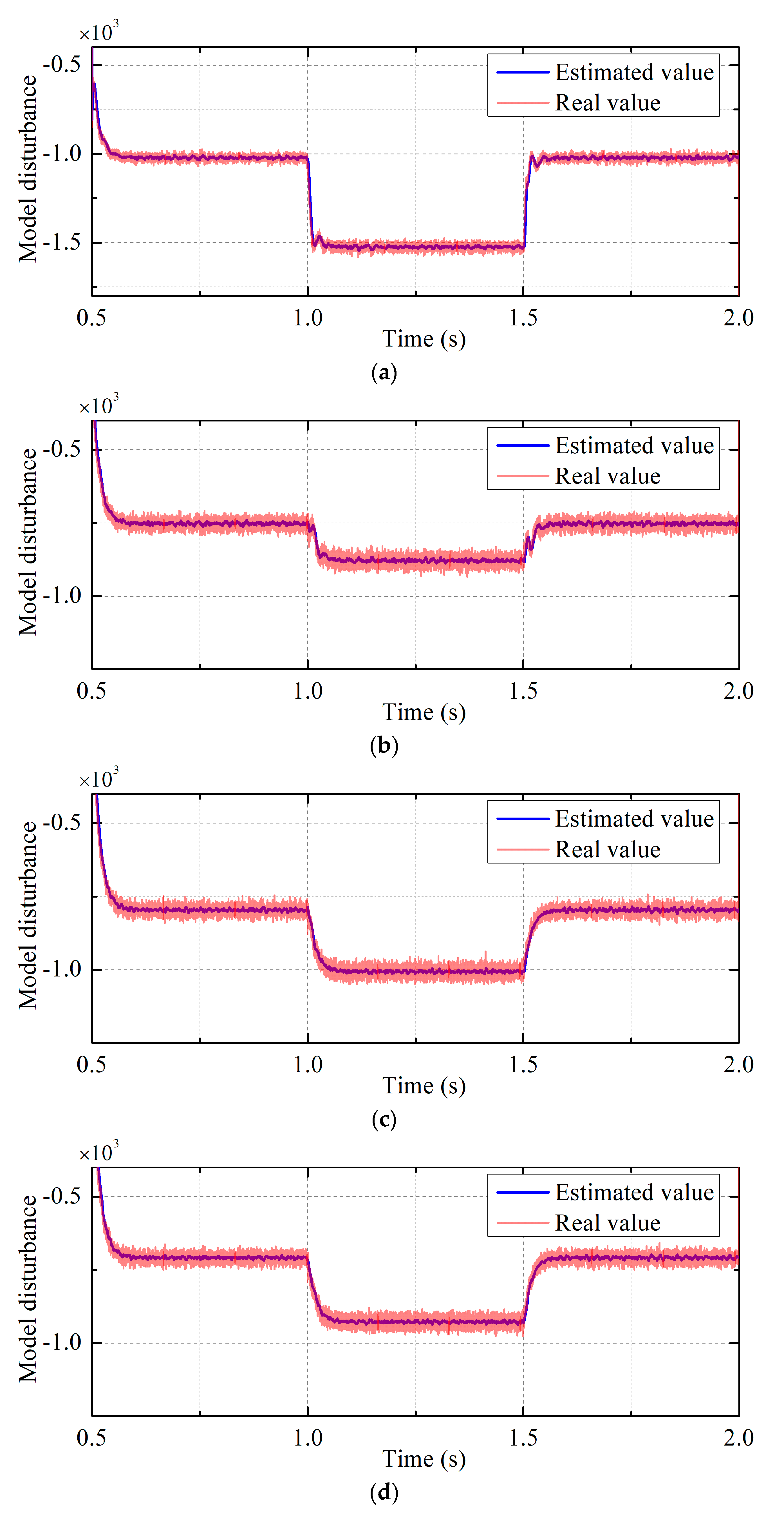
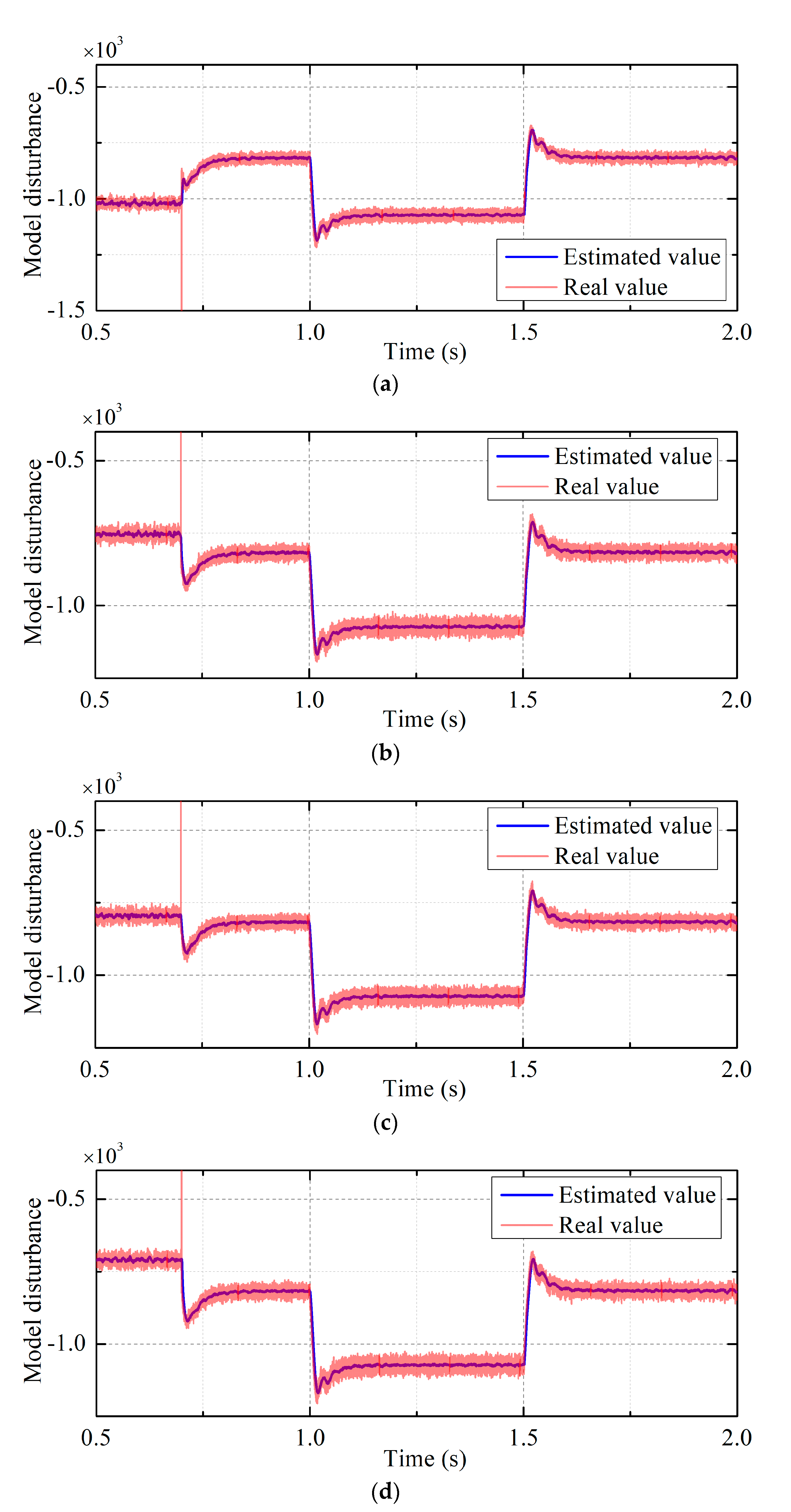
3.1. Linear Extended State Observer

The linear extended state observer is a key element for establishing the ADRC-based distributed secondary frequency controller. Hence, design of the extended state observer is elaborated. Consider the control input and output of the frequency controller as ui = ωni and yi = ωi, and the lumped model disturbance is given by:
F i = ω ˙ n i ω c ω i + m p i ω c ( P 0 v o d i i o d i v o q i i o q i )
According to (6), (5) can be rewritten as:
y ˙ i = ω c u i + F i
Regarding the model disturbance Fi in (5) as an extended state, an augmented state space equation can be written as:
{ z ˙ i = A z i + B u i + W ψ i y i = C z i
where zi= [zi,1 zi,2]T, zi,1 = ωi, zi,2 = Fi and matrixes A, B, W, C are given as follows:
A = [ 0 1 0 0 ] ;   B = [ b 0 0 ] ;   W = [ 0 1 ] ;   C = [ 1 0 ] T
Then, the mathematic expression of a linear extended state observer can be given as:
z ^ ˙ i = = A z ^ i + B u i + l C ( z i z ^ i )
where z ^ i = ( z ^ i , 1 ,   z ^ i , 2 ) T = ( y ^ i ,   F ^ i ) T , l is the observer gain vector to be determined. For a second-order linear extended state observer, l can be designed by [38,39]:
l = [ β 1 β 2 ] = [ 2 ω 0 ω 0 2 ] T
According to (9) and (10), the characteristic polynomial of extended state observer can be expressed as:
λ ( s ) = ( s + ω 0 ) 2
where λ is the symbol of characteristic function and s is the Laplace operator. According to (11), there are two same poles lying at (−ω0, 0), which means that the bandwidth of the extended state observer is ω0. It can also be inferred from (10) that observer gain tuning of extended state observer is simplified to the selection of bandwidth ω0.

3.2. Proposed Consensus-Based Distributed Secondary Frequency Controller Design

As is shown in Figure 3, there exists frequency deviation in the microgrid with only droop control strategy. The basic objective of the distributed secondary frequency control is to restore frequency of the DGs to a given frequency reference ωref, i.e.,
lim t ω i = lim t ω j = ω r e f
Thus, we form a distributed secondary frequency control law as follows:
u i = 1 ω c { c [ j N i a i j ( ω i ω j ) + g i ( ω i ω r e f ) ] z ^ i , 2 }
where c is a coupling gain related to the frequency convergence rate. It can be seen that the proposed control low needs only the neighboring frequency information and dispenses with integral controller.
Further, from Figure 3, it is easy to understand that entitling the DGs with only the frequency restoration control may deteriorate the accuracy of active power sharing though it can restore the microgrid frequency to the desired value. As the power-electronic-interfaced DG is featured with limited over-current capability, the inaccuracy of active power sharing may result in disconnection of some DGs due to self-protection reaction. Hence, in this occasion, another objective is also expected for the distributed frequency control algorithm, which can be expressed as follows:
lim t m p i P i = lim t m p j P j
Indicated by the frequency droop control characteristic in (4) and principle presented in Figure 3, (15) should be satisfied to guarantee active power sharing among the DGs.
lim t u i u j = 1
Therefore, an improved control law to achieve both active power sharing and frequency restoration can be given as follows:
u i = 1 ω c { c [ j N i a i j ( ω i ω j ) + g i ( ω i ω r e f ) ] - j N i a i j ( u i u j ) z ^ i , 2 }
Assuming that the voltage regulation is considered to be taken over by droop control algorithm, the whole control diagram is described in Figure 4 based on (13) and (16).

3.3. Stability Analysis and Controller Parameter Selection

3.3.1. Stability Analysis of Proposed Control Law without Active Power Sharing

The stability of the proposed distributed secondary frequency controller is analyzed, and based on the closed-loop stability constraint, selection of the controller parameter is then determined.
Considering a microgrid with N DGs, define the global state vectors as Y = [y1 y2yN]T, U = [u1 u2uN]T, F = [F1 F2Fn]T, 1N = [1 1 … 1]T. According to (5), one can have
Y ˙ = ω c U + F
Define the global frequency tracking error vector E as
E = Y 1 N y 0
Based on the defined global state vectors and frequency tracking error, (13) can be developed into the global state space equation described as follows:
U = c ω c ( L + G ) E 1 ω c F ^
Substituting (19) into (17)), dynamics of the global frequency tracking error vector E without active power sharing control can be given by
E ˙ = c ( L + G ) E F ^ + F
According to (20), the global frequency tracking error vector can be derived by
E ( t ) = e c ( L + G ) t E ( 0 ) + 0 t e c ( L + G ) ( t τ ) [ F ( τ ) F ^ ( τ ) ] d τ
In (21), the global frequency tracking error vector E(t) will be asymptotic stability if the two terms in the right side of the equation are both asymptotic stability.
Lemma 1
([32]). Let us consider the Laplacian Matrix L associated with a connected undirected graph with N nodes and G be a diagonal matrix expressed by G = diag[(gi)] with all diagonal elements being nonnegative and at least one of them be strictly positive. Then, G + L is a positive definitive matrix.
According to Lemma 1, eigenvalues of matrix −c(L + G) satisfy:
Re { λ [ c ( L + G ) ] } 0
For the aforementioned first term, it can asymptoticly converge into zero based on (22). The second term in right side of Equation (21) can be rearranged by
0 t e c ( L + G ) ( t τ ) [ F ( τ ) F ^ ( τ ) ] d τ = e c ( L + G ) t 0 t M e Λ 1 τ M - 1 [ F ( τ ) F ^ ( τ ) d τ
Since
lim t | | 0 t e c ( L + G ) ( t τ ) [ F ( τ ) F ^ ( τ ) ] d τ | | lim t | | M e Λ 1 t M - 1 0 t M e Λ 1 τ M - 1 [ F ( τ ) F ^ ( τ ) ] d τ | | lim t | | M | | e | | Λ 1 | | t | | M 1 | | 0 t e | | Λ 1 | | τ | | F ( τ ) F ^ ( τ ) | | d τ
Assume that model disturbance defined in (6) are continuous and differentiable and its derivative is equal to zero in the steady state. Then, if the observer gains are properly selected based the design guidance, estimation errors of the model disturbance will asymptotically converge into zero, i.e.,
lim t [ F ( τ ) F ^ ( τ ) ] = 0
Since
lim t | | M | | e | | Λ 1 | | t | | M 1 | | 0 t e | | Λ 1 | | τ | | F ( τ ) F ^ ( τ ) | | d τ = lim t 0 t e | | Λ 1 | | τ | | F ( τ ) F ^ ( τ ) | | d τ | | M | | e | | Λ 1 | | t | | M 1 | | = lim t | | F ( τ ) F ^ ( τ ) | | | | M | | | M 1 | |
Referring to (26), it can be obtained that
lim t 0 t e c ( L + G ) ( t τ ) [ F ( τ ) F ^ ( τ ) ] d τ = 0
Hence, one can obtain that global frequency tracking error vector dynamic in (20) is asymptotically stable, i.e.,
lim t E ( t ) = 0

3.3.2. Stability Analysis of Proposed Control Law with Active Power Sharing
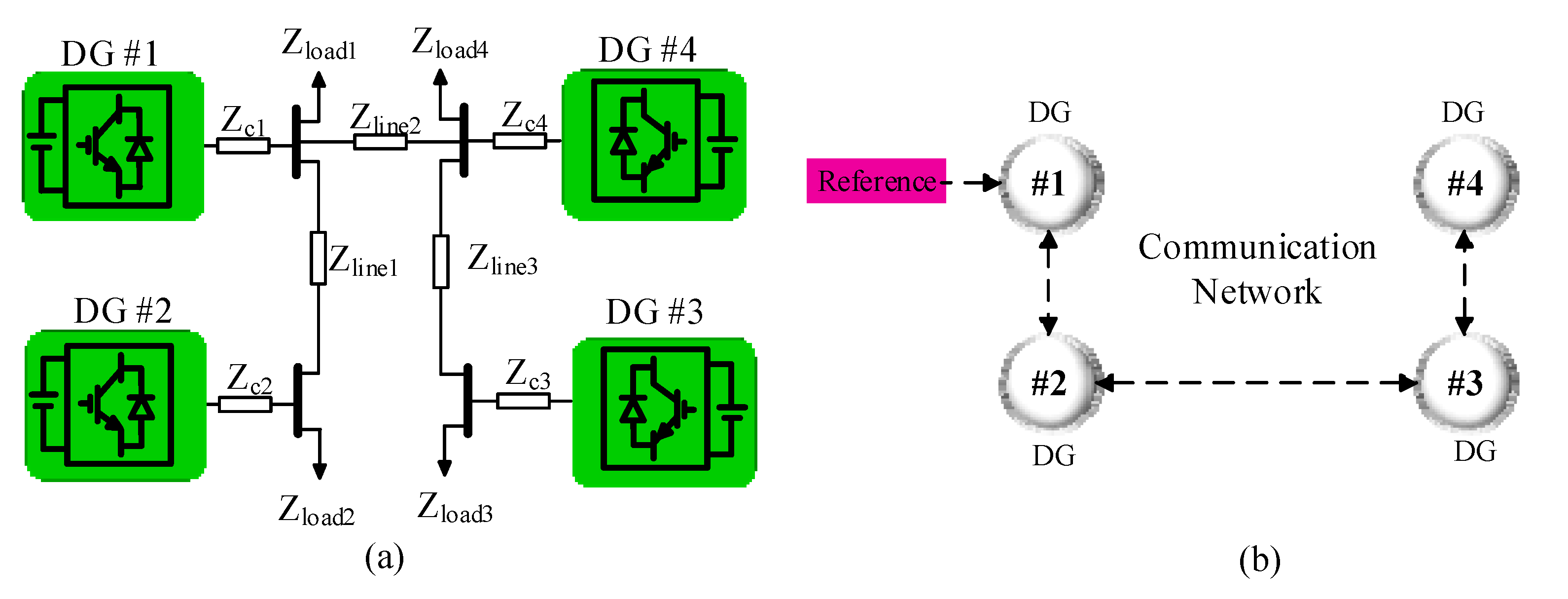
Based on the defined global state vectors, (16) can be developed into the global state space equation as described as
U = c ω c ( L + G ) E c ω c L U 1 ω c F ^
After simple mathematical manipulation, (29) can be rearranged as follows:
U = c ( ω c I N + c L ) 1 ( L + G ) E ( ω c I N + c L ) 1 F ^
Substituting (30) into (17), dynamics of the global frequency tracking error vector E with active power sharing can be given by
E ˙ = c ω c ( ω c I N + c L ) 1 ( L + G ) E ω c ( ω c I N + c L ) 1 F ^ + F
Lemma 2.
Let us consider the Laplacian Matrix L associated with a connected undirected graph with N nodes. Letωc> 0 and c > 0. Then,ωcIN+ cL is a positive-definite matrix. □
Proof of Lemma 2.
Let λi be the ordered eigenvalues of L, i.e., 0 = λ1λ2 ≤ ··· ≤ λN. Then, the eigenvalues of Matrix ωcIN + cL can be derived as ςi = ωc + cλi. Since λI ≥ 0 and ωc > 0 and c > 0, one can obtain that ςi > 0. Therefore, ωcIN + cL is a positive-definite matrix.
Since it has ωc >> 1, the gain of the second term at the right side of Equation (31) has the following approximation as
ω c ( ω c I N + c L ) 1 = ( I N + c ω c L ) 1 I N
Hence, the dynamics of global frequency tracking error vector in (31) can be further approximated as
E ˙ = c ω c ( ω c I N + c L ) 1 ( L + G ) E + F F ^
The solution of Equation (33) can be given by
E ( t ) = e c ω c ( ω c I N + c L ) 1 ( L + G ) t E ( 0 ) + 0 t e c ω c ( ω c I N + c L ) 1 ( L + G ) ( t τ ) [ F ( τ ) F ^ ( τ ) ] d τ
Since matrixes ωcIN + cL and L + G are both are positive-definitive, the product of ωcIN + cL and L + G is also positive-definitive. Correspondingly, the system matrix −cωc(ωcIN + cL)(L + G) can be proved to be Hurwitz. Hence, (34) can be converted into
E ( t ) = ρ e Λ 2 t ρ 1 E ( 0 ) + ρ e Λ 2 t ρ 1 0 t e Λ 2 τ [ F ( τ ) F ^ ( τ ) ] d τ
It is easy to prove that
lim t ρ e Λ 2 t ρ 1 E ( 0 ) = 0
And also
lim t ρ e Λ 2 t ρ 1 0 t e Λ 2 τ [ F ( τ ) F ^ ( τ ) ] d τ = 0
Based on (36) and (37), it can make a conclusion that global frequency tracking error vector E can asymptotically convergence to zero under the control law shown in (16).

4. Results

To further verify the effectiveness of the proposed approach, an islanded AC microgrid consisting of 4 DGs is established in this section. The simulated microgrid is depicted in Figure 5a and information interactions among the DGs follow the communication network shown in Figure 5b. In the studied microgrid, the rated voltage and frequency are set as 380 V and 50 Hz. The main circuit parameters and control parameters are given in Table 1. To explore the performance of the proposed controller, four different case studies are carried out, which will be discussed next.

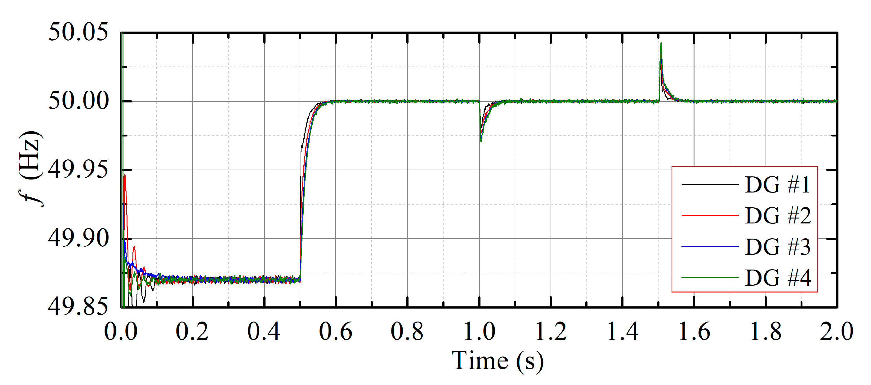
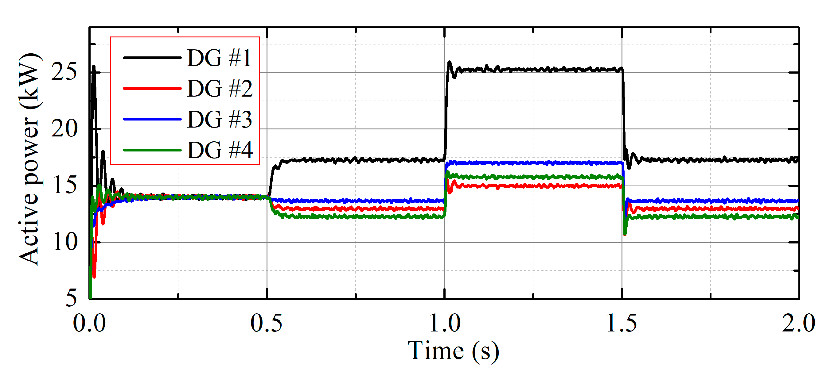
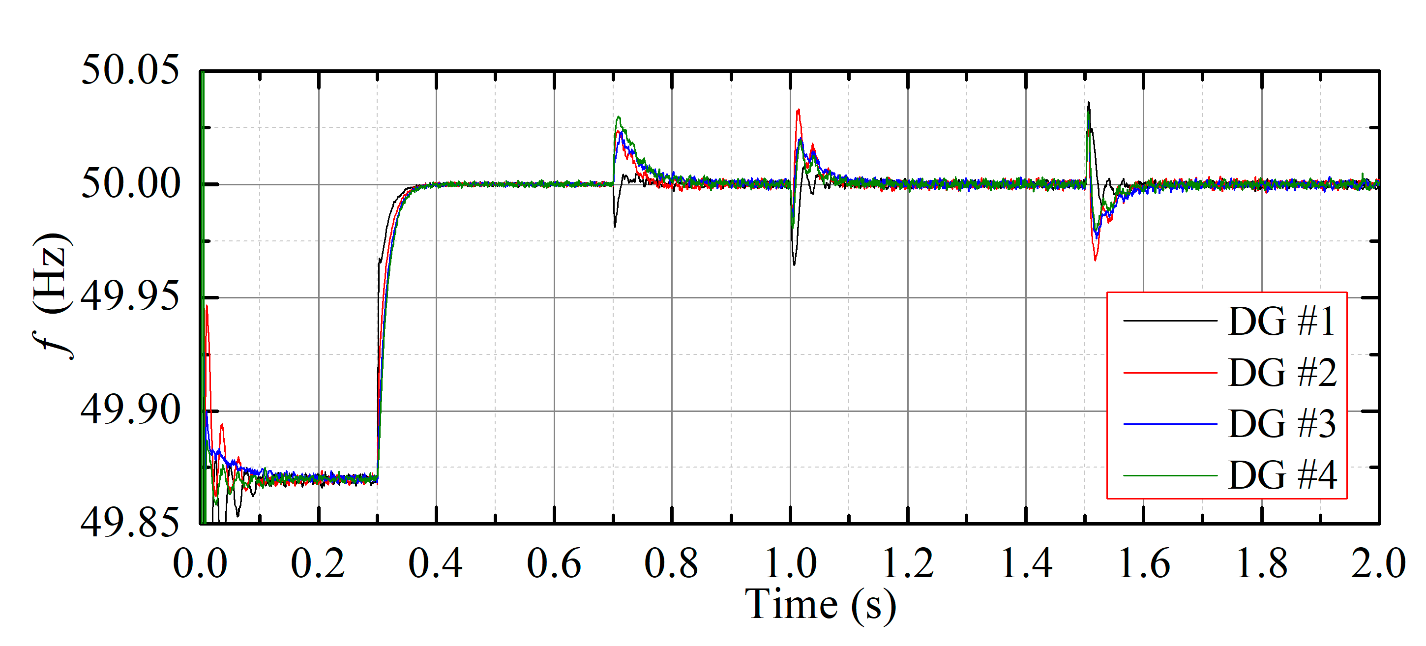
4.1. Case Study 1: Frequency Restoration without Active Power Sharing Control

In this case study, control performance of the proposed distributed secondary control approach without the active power sharing control is tested. As frequency restoration and active power sharing are two control objectives, the voltage regulation is undertaken by primary control all the time. The simulation test is conducted as follows:
(1) At the beginning, all the DGs in the studied microgrid operate under the droop control only;
(2) At t = 0.5 s, the proposed distributed secondary frequency control is activated with the active power sharing control unenabled;
(3) At t = 1 s, to imitate a load increase disturbance, the active power loads (P = 5 kW × 4) are added at the local side of the DGs;
(4) At t = 1.5 s, the added active power loads are removed to simulate the load decrease disturbance.
Simulations results of the tested 4-DGs-based microgrid with the proposed ADRC-based distributed secondary frequency control (without active power sharing control) are selected to be presented as shown in Figure 6, Figure 7 and Figure 8.
Figure 6 shows the frequency responses of the DGs. It is observed that at the initial stage, frequency deviation below the frequency reference exists under the primary control. Since the microgrid frequency is a global state, the frequencies of the four DGs remain consistent in the whole process.
As shown in Figure 7, the output active power of the four DGs are consistent, due to the same active power droop gains. When the proposed distributed secondary frequency controller is activated, frequencies of the DGs are smoothly synchronized to the frequency reference value at a fast convergence rate and with no overshot. However, as it also can be seen that the frequency restoration deteriorates the active power sharing performance, which should also be paid attention in occasions where the capacities of the DGs are seriously limited. The frequency restoration performance is recovered after short transients against a load increase disturbance and a load increase set at t = 1 s and t = 1.5 s, respectively.
Figure 8 describes the real and estimated model disturbances for the four DGs in the studied microgrid. An accurate estimation on the model disturbance in the DG inverter will determine the tracking performance and disturbance rejection capability under the proposed frequency distributed secondary control approach. It can be seen in Figure 8a–d that the estimated values of the model disturbances in DGs #1~#4 closely agree with the real values, which indicates the effectiveness of the proposed control approach.

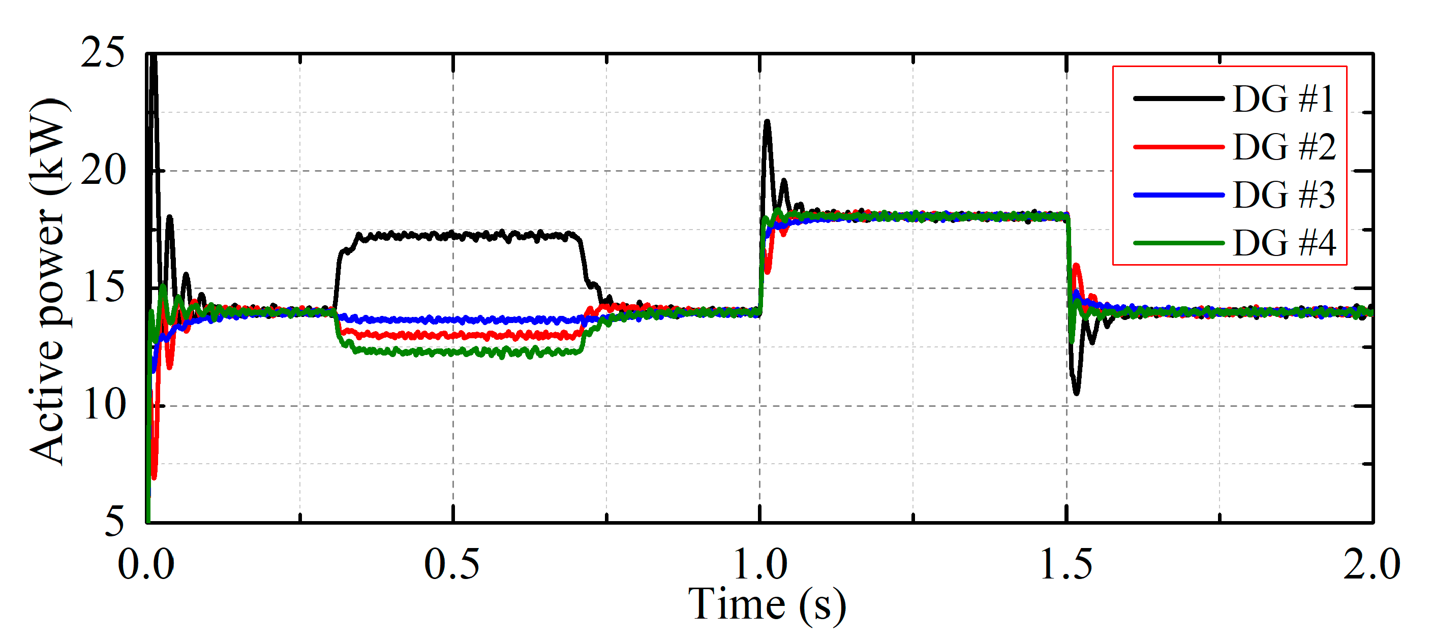
4.2. Case Study 2: Frequency Restoration with Active Power Sharing Control

Case study 2 verifies the control performance of the proposed ADRC-based distributed secondary frequency control approach considering the active power sharing control. The microgrid voltages are regulated under the droop control all the time.
The simulation actions in case study 2 is set as follows:
(1) To start up, the studied microgrid operates under the droop control only;
(2) At t = 0.3 s, the proposed distributed secondary frequency control is activated with the active power sharing control unenabled;
(3) At t = 0.6 s, the active power sharing control is enabled;
(4) At t = 1 s, additional active power loads (P = 5 kW × 4) are added at each local side of the DGs to imitate the load increase disturbance;
(5) At t = 1.5 s, the added active power loads are removed from the microgrid;
Referring to the results presented in Figure 6 and Figure 7, accuracy of the active power sharing is deteriorated if distributed secondary frequency control algorithm works only. As shown in Figure 9 and Figure 10, this active power discrepancy can be removed after the active power sharing control algorithm is activated while the frequency restoration is also maintained. It can also be observed that the frequency restoration and active power sharing accuracy are well kept against the sudden load change disturbances added at t = 1 s and t = 1.5 s, respectively. Compared with case study 1, where the active power sharing control is not included, both frequency responses and output active power of the four DGs go through more intensive transients against the load change disturbances. A possible reason behind it is that the approximation in (32) may result in this kind of difference. Figure 11a–d shows that the estimated and real values of the model disturbances fit well which also indicates a good disturbance rejection and tracking performance can be reached under the proposed approach.

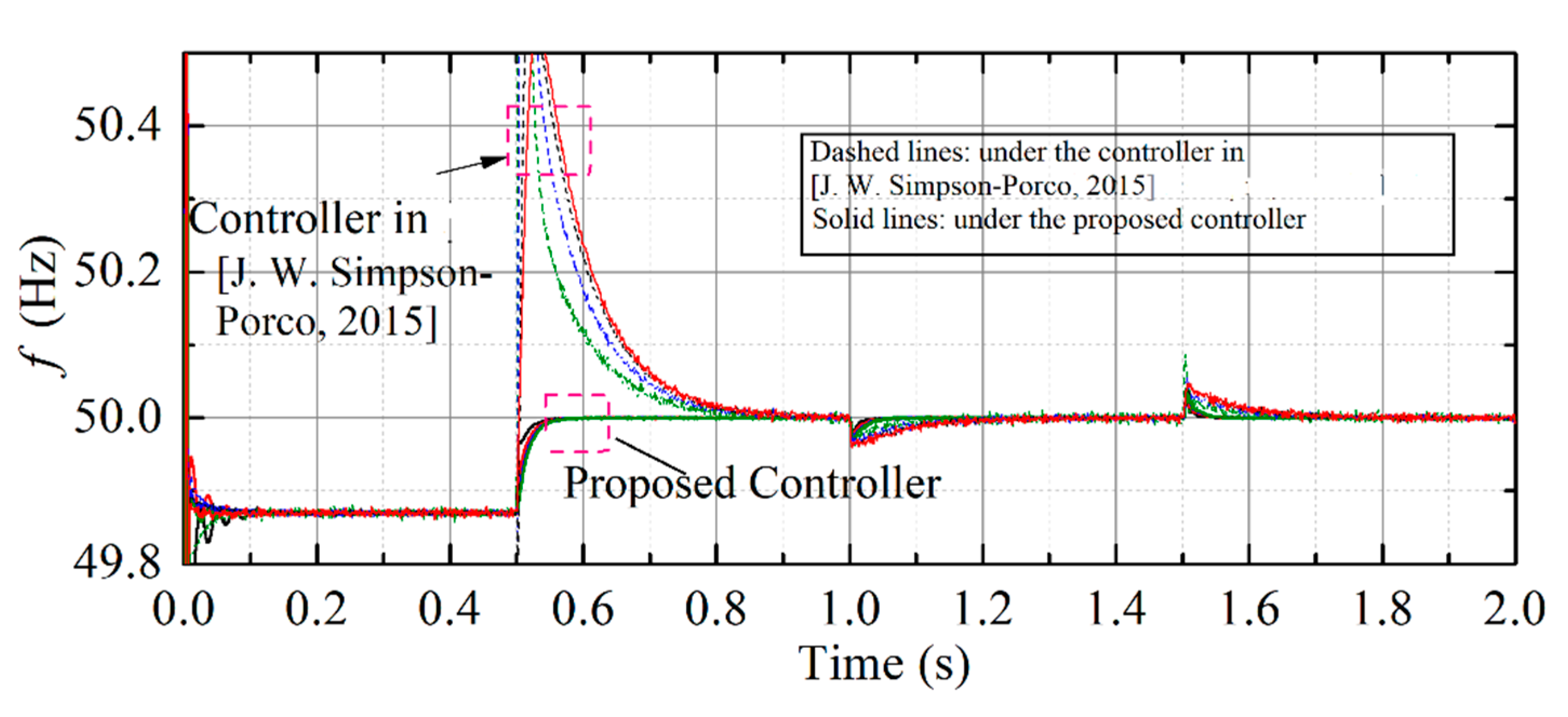
4.3. Case Study 3: Dynamic Performance Comparsion with Convention Integrator-Based Distributed Secondary Frequency Controller

To explore the disturbance rejection performance of the proposed approach, the proposed distributed secondary frequency controller is further compared with the integrator-based distributed secondary frequency controller proposed in [16]. The simulation scene in this case is set the same as that in case study 1. The frequency response is shown in Figure 12.
As indicated in Figure 12, one can find the frequency overshoot when the integrator-based distributed secondary frequency controller (dashed line) is enabled. The overshoot can be mitigated or removed by reducing the integrator coefficient; however, the settling time will be prolonged, referred to in the literature [16]. By contrast, the frequency responses are very smooth as the proposed distributed frequency controller is enabled (solid line). Additionally, the dynamic performance of the proposed controller under load increase and decrease is also improved compared with the referred to method.

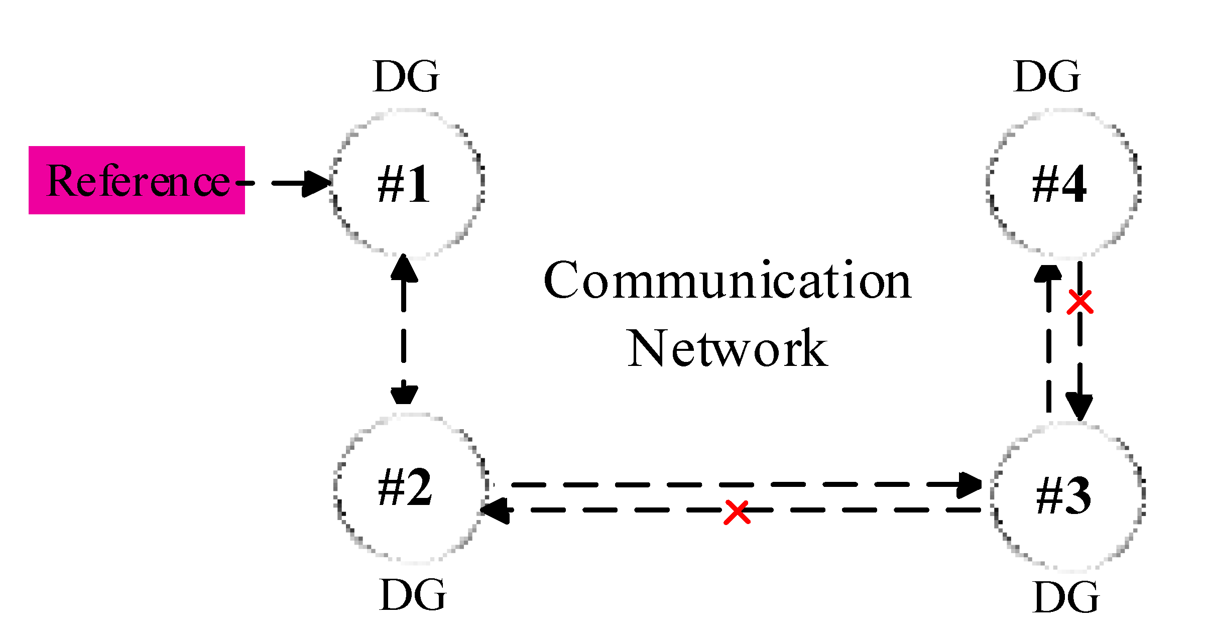
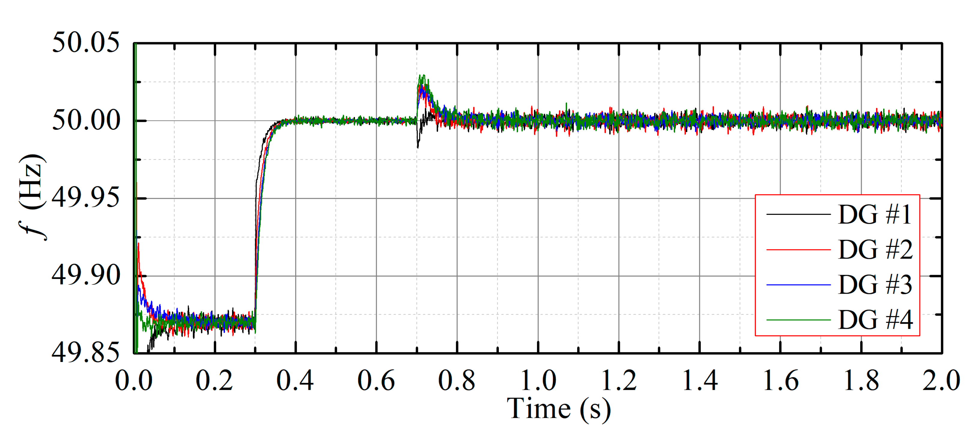
4.4. Case Study 4: Comunication Failure Roustness Test

The communication failure robustness performance of the proposed controller is further tested. In this case study, a communication failure situation is simulated by breaking the communication link from DG #3 to DG #2 and DG #4 to DG #3, as shown in Figure 13. The proposed controller with frequency restoration control only is enabled at t = 0.3 s and the active power sharing control is then added at t = 0.7 s.
Figure 14 shows the frequency responses of the DGs. It can be seen that the frequency restoration is not affected by the communication failure. The active power sharing, indicated in Figure 15, is also maintained in the condition of communication failure. The obtained results validate the communication failure robustness of the proposed distributed secondary frequency control approach.

5. Conclusions

In this paper, a consensus-based distributed secondary frequency control method is proposed. The nonlinear dynamic in the frequency control model is considered and then estimated using a second-order extended state observer. As a consequence, the nonlinear frequency control model is modified into a quasi-linear model. Based on the obtained quasi-linear model, a proportional distributed control law is designed to achieve frequency restoration and active power sharing. The stability analysis and stability constraint for the proposed approach is researched, which can also guide control parameter selection. The proposed distributed secondary frequency control approach is verified on a 4-DGs-based tested microgrid. Results show that the proposed approach can achieve satisfactory frequency restoration performance, as well as active power sharing, based on scattered communication topology.

Author Contributions

Conceptualization, W.L. and M.Z.; methodology, W.L., M.Z. and Y.D.; software, W.L. and M.Z.; validation, W.L., M.Z. and Y.D.; investigation, Y.D.; resources, Y.D.; writing—original draft preparation, W.L. and M.Z.; writing—review and editing, Y.D.; supervision, M.Z. and Y.D.; project administration, W.L.; funding acquisition, W.L. and Y.D. All authors have read and agreed to the published version of the manuscript.

Funding

This work was supported in part by the Hunan Provincial Natural Science Foundation of China under Grant 2020JJ4158 and 2021JJ40029, in part by the Scientific Research Fund of Hunan Provincial Education Department under Grant 19A084 and 19B100.

Conflicts of Interest

The authors declare no conflict of interest.

Nomenclature

ωcBandwidth of low-pass filter
FiLumped model disturbance
ωni(ui)Secondary frequency control input
ωiAngular speed
ziAgumented system state vector
z ^ i Estimated system state vector
lObserver gain vector
ω0Bandwidth of extended state observer
cFrequency coupling gain
P0, Q0Rated active and reactive power.
Pi, Qifiltered active and reactive power.
mPiDroop coefficients of DG #i.
NNumber of DG unit
YGlobal system output vector
UGlobal system control vector
FGlobal model disturbance vector
EGlobal tracking error vector
LLaplace Matrix
GPinned Matrix
giPinned gain
F ^ iGlobal estimated disturbance vector
β1, β2Observer gain

References

  1. Rahbar, K.; Chai, C.C.; Zhang, R. Energy cooperation optimization in microgrids with renewable energy integration. IEEE Trans. Smart Grid 2018, 9, 1482–1493. [Google Scholar] [CrossRef]
  2. Mai, T.; Hand, M.; Baldwin, S.; Wiser, R.; Brinkman, G.; Denholm, P.; Arent, D.; Porro, G.; Sandor, D.; Hostick, D.; et al. Renewable electricity futures for the united states. IEEE Trans. Sustain. Energy 2014, 5, 372–378. [Google Scholar] [CrossRef]
  3. Du, E.; Zhang, N.; Hodge, B.; Wang, Q.; Kang, C.; Kroposki, B.; Xia, Q. The role of concentrating solar power toward high renewable energy penetrated power systems. IEEE Trans. Power Syst. 2018, 33, 6630–6641. [Google Scholar] [CrossRef]
  4. Bollen, M.H.J.; Sannino, A. Voltage control with inverter-based distributed generation. IEEE Trans. Power Deliv. 2005, 20, 519–520. [Google Scholar]
  5. Cui, Q.; Bai, X.; Dong, W. Collaborative planning of distributed wind power generation and distribution network with large-scale heat pumps. CSEE J. Power Energy Syst. 2019, 5, 335–347. [Google Scholar]
  6. Che, L.; Shahidehpour, M.; Alabdulwahab, A.; Al-Turki, Y. Hierarchical coordination of a community microgrid with AC and DC microgrids. IEEE Trans. Smart Grid 2015, 6, 3042–3051. [Google Scholar] [CrossRef]
  7. Wan, Q.; Bian, Y.; Chen, Y. Research on a Micro-Grid Frequency Modulation Strategy Based on Optimal Utilization of Air Conditioners. Energies 2016, 9, 1085. [Google Scholar] [CrossRef] [Green Version]
  8. Zhou, S.; Gu, Y.; Song, W.; Wang, C.; Bai, F.; Cai, Y. Research on control strategy of grid-connected inverter in microgrid System. In Proceedings of the 2019 IEEE 3rd Conference on Energy Internet and Energy System Integration, Changsha, China, 8–10 November 2019; pp. 392–396. [Google Scholar]
  9. Patarroyo-Montenegro, J.F.; Andrade, F.; Guerrero, J.M.; Vasquez, J.C. A linear quadratic regulator with Optimal Reference tracking for three-phase inverter-based islanded microgrids. IEEE Trans. Power Electron. 2021, 36, 7112–7122. [Google Scholar] [CrossRef]
  10. Andrade, A.I.; Blasco-Gimenez, R.; Peña, R.S. Constant power control of grid connected inverters during unbalanced faults. In Proceedings of the 2013 15th European Conference on Power Electronics and Applications (EPE), Lille, France, 2–6 September 2013; pp. 1–7. [Google Scholar]
  11. Meng, X.; Liu, J.; Liu, Z. A generalized droop control for grid-supporting inverter based on comparison between traditional droop control and virtual synchronous generator control. IEEE Trans. Power Electron. 2019, 34, 5416–5438. [Google Scholar] [CrossRef]
  12. Bassey, O.; Butler-Purry, K.L. Black Start Restoration of Islanded Droop-Controlled Microgrids. Energies 2020, 13, 5996. [Google Scholar] [CrossRef]
  13. Meng, L.; Savaghebi, M.; Andrade, F.; Vasquez, J.C.; Guerrero, J.M.; Graells, M. Microgrid central controller development and hierarchical control implementation in the intelligent microgrid lab of Aalborg University. In Proceedings of the 2015 IEEE Applied Power Electronics Conference and Exposition (APEC), Charlotte, NC, USA, 15–19 March 2015; pp. 2585–2592. [Google Scholar]
  14. Shafiee, Q.; Guerrero, J.M.; Vasquez, J.C. Distributed secondary control for islanded microgrids—A novel approach. IEEE Trans. Power Electron. 2014, 29, 1018–1031. [Google Scholar] [CrossRef] [Green Version]
  15. Bidram, A.; Davoudi, A.; Lewis, F.L.; Guerrero, J.M. Distributed cooperative secondary control of microgrids using feedback linearization. IEEE Trans. Power Syst. 2013, 28, 3462–3470. [Google Scholar] [CrossRef] [Green Version]
  16. Simpson-Porco, J.W.; Shafiee, S.Q.; Dörfler, F.; Vasquez, J.C.; Guerrero, J.M.; Bullo, F. Secondary frequency and voltage control of islanded microgrids via distributed averaging. IEEE Trans. Ind. Electron. 2015, 62, 7025–7038. [Google Scholar] [CrossRef]
  17. Dehkordi, N.M.; Sadati, N.; Hamzeh, M. Distributed robust finite-time secondary voltage and frequency control of islanded microgrids. IEEE Trans. Power Syst. 2017, 32, 3648–3659. [Google Scholar] [CrossRef]
  18. Zuo, S.; Davoudi, A.; Song, Y.; Lewis, F.L. Distributed finite-time voltage and frequency restoration in islanded AC microgrids. IEEE Trans. Ind. Electron. 2016, 63, 5988–5997. [Google Scholar] [CrossRef]
  19. Chen, G.; Lewis, F.L.; Feng, E.N.; Song, Y. Distributed optimal active power control of multiple generation systems. IEEE Trans. Ind. Electron. 2015, 62, 7079–7090. [Google Scholar] [CrossRef]
  20. Yang, Z.; Xiang, J.; Li, Y. Distributed consensus based supply–demand balance algorithm for economic dispatch problem in a smart grid with switching graph. IEEE Trans. Ind. Electron. 2017, 64, 1600–1610. [Google Scholar] [CrossRef]
  21. Binetti, G.; Davoudi, A.; Lewis, F.L.; Naso, D.; Turchiano, B. Distributed consensus-based economic dispatch with transmission losses. IEEE Trans. Power Syst. 2014, 29, 1711–1720. [Google Scholar] [CrossRef]
  22. Liu, W.; Wen, Z.; Shen, Y.; Zhang, Z. Reinforcement learning-based distributed secondary optimal control for multi-microgrids. In Proceedings of the 2017 IEEE Conference on Energy Internet and Energy System Integration (EI2), Beijing, China, 26–28 November 2017; pp. 1–4. [Google Scholar]
  23. Smith, E.; Robinson, D.A.; Agalgaonkar, A. Cooperative secondary voltage control of static converters in a microgrid using model-free reinforcement learning. In Proceedings of the 2019 21st European Conference on Power Electronics and Applications (EPE ‘19 ECCE Europe), Genova, Italy, 3–5 September 2019; pp. 1–10. [Google Scholar]
  24. Liu, Z.; Luo, Y.; Zhuo, R.; Jin, X. Distributed reinforcement learning to coordinate current sharing and voltage restoration for islanded DC microgrid. J. Mod. Power Syst. Clean Energy 2018, 6, 364–374. [Google Scholar] [CrossRef] [Green Version]
  25. Liu, S.; Wang, X.; Liu, P.X. Impact of communication delays on secondary frequency control in an islanded microgrid. IEEE Trans. Ind. Electron. 2015, 62, 2021–2031. [Google Scholar] [CrossRef]
  26. Lai, J.; Zhou, H.; Lu, X.; Yu, X.; Hu, W. Droop-based distributed cooperative control for microgrids with time-varying delays. IEEE Trans. Smart Grid 2016, 7, 1775–1789. [Google Scholar] [CrossRef]
  27. Wu, X.; Shen, C.; Iravani, R. A distributed, cooperative frequency and voltage control for microgrids. IEEE Trans. Smart Grid 2018, 9, 2764–2776. [Google Scholar] [CrossRef]
  28. Ullah, S.; Khan, L.; Jamil, M.; Jafar, M.; Mumtaz, S.; Ahmad, S. A finite-time robust distributed cooperative secondary control protocol for droop-based islanded AC microgrids. Energies 2021, 14, 2936. [Google Scholar] [CrossRef]
  29. Guo, F.; Wen, C.; Mao, J.; Song, Y. Distributed secondary voltage and frequency restoration control of droop-controlled inverter-based microgrids. IEEE Trans. Ind. Electron. 2015, 62, 4355–4364. [Google Scholar] [CrossRef]
  30. Cady, S.T.; Domínguez-García, A.D.; Hadjicostis, C.N. A distributed generation control architecture for islanded AC microgrids. IEEE Trans. Control Syst. Technol. 2015, 23, 1717–1735. [Google Scholar] [CrossRef]
  31. Islam, S.; Liu, P.X.; Saddik, A. Distributed robust adaptive finite-time voltage control for microgrids with uncertainty. In Proceedings of the 2017 IEEE International Conference on Systems, Man, and Cybernetics (SMC), Banff, AB, Canada, 5–8 October 2017; pp. 2200–2202. [Google Scholar]
  32. Pilloni, A.; Pisano, A.; Usai, E. Robust finite-time frequency and voltage restoration of inverter-based microgrids via sliding-mode cooperative control. IEEE Trans. Ind. Electron. 2018, 65, 907–917. [Google Scholar] [CrossRef]
  33. Han, J. From PID to active disturbance rejection control. IEEE Trans. Ind. Electron. 2009, 56, 900–906. [Google Scholar] [CrossRef]
  34. Gao, Z.; Huang, Y.; Han, J. An alternative paradigm for control system design. In Proceedings of the 40th IEEE Conference on Decision and Control (Cat. No.01CH37228), Orlando, FL, USA, 4–7 December 2001; Volume 5, pp. 4578–4585. [Google Scholar]
  35. Gaol, Q. On stability analysis of active disturbance rejection control for nonlinear time-varying plants with unknown dynamics. In Proceedings of the 2007 46th IEEE Conference on Decision and Control, New Orleans, LA, USA, 12–14 December 2007. [Google Scholar]
  36. Brabandere, K.; Bolsens, B.; Keybus, J.; Woyte, A.; Driesen, J.; Belmans, R. A voltage and frequency droop control method for parallel inverters. IEEE Trans. Power Electron. 2007, 22, 1107–1115. [Google Scholar] [CrossRef]
  37. Mahmood, H.; Michaelson, D.; Jiang, J. Reactive power sharing in islanded microgrids using adaptive voltage droop control. IEEE Trans. Smart Grid. 2015, 6, 3052–3060. [Google Scholar] [CrossRef]
  38. Xue, W.; Bai, W.; Yang, S.; Song, K.; Huang, Y.; Xie, H. ADRC with adaptive extended state observer and its application to air–fuel ratio control in gasoline engines. IEEE Trans. Ind. Electron. 2015, 62, 5847–5857. [Google Scholar] [CrossRef]
  39. Wu, D.; Chen, K. Design and analysis of precision active disturbance rejection control for noncircular turning process. IEEE Trans. Ind. Electron. 2009, 56, 2746–2753. [Google Scholar]
Figure 1. Schematic diagram of primary control in microgrid.
Energies 15 03184 g001
Figure 2. Block diagram of droop control.
Energies 15 03184 g002
Figure 3. Motivation of the distributed secondary frequency control with active power sharing.
Energies 15 03184 g003
Figure 4. Control diagram of the tested microgrid.
Energies 15 03184 g004
Figure 5. Single-line diagram of the tested islanded microgrid. (a) Microgrid structure. (b) Communication topology.
Energies 15 03184 g005
Figure 6. Case study of the 1-DGs frequency responses.
Energies 15 03184 g006
Figure 7. Case study of the 1-DGs output active power.
Energies 15 03184 g007
Figure 8. Case study 1-real and estimated model disturbances of (a) DG #1, (b) DG #2, (c) DG #3 and (d) DG #4.
Energies 15 03184 g008
Figure 9. Case study of the 2-DGs frequency responses.
Energies 15 03184 g009
Figure 10. Case study of the 2-DGs output active power.
Energies 15 03184 g010
Figure 11. Case study 2-real and estimated model disturbances of (a) DG #1, (b) DG #2, (c) DG #3 and (d) DG #4.
Energies 15 03184 g011
Figure 12. Case study of the 3-DGs frequency responses. The black line is for DG #1 and The red, blue and green are for DG #2, DG#3 and DG #4, respectively. Reprinted from ref. [16].
Energies 15 03184 g012
Figure 13. Communication topology after communication failure.
Energies 15 03184 g013
Figure 14. Case study of the 4-DGs frequency responses.
Energies 15 03184 g014
Figure 15. Case study of the 4-DGs output active power.
Energies 15 03184 g015
Table 1. System parameters of the Tested Microgrid.
DG ParametersDG #1DG #2DG #3DG #4
Droop controlmP1 × 10−51 × 10−51 × 10−51 × 10−5
nQ3 × 10−23 × 10−33 × 10−33 × 10−3
Voltage controlKPvi0.120.120.120.12
KIvi180180180180
Current controlKPci15151515
KIci20,00020,00020,00020,000
LC filterLfi1.35 mH1.35 mH1.35 mH1.35 mH
Cfi50 μF50 μF50 μF50 μF
Rfi0.2 Ω0.2 Ω0.2 Ω0.2 Ω
Connector impedance ZciRci0.014 Ω0.014 Ω0.014 Ω0.014 Ω
Lci0.234 mH0.834 mH0.834 mH0.634 mH
LineZline1 Zline2 Zline3
Rline0.14 Ω 0.14 Ω 0.24 Ω
Lline0.21 mH 0.86 mH 0.16 mH
LoadZload1 Zload2 Zload3 Zload4
Rload10 Ω 10 Ω 10 Ω 10 Ω
Publisher’s Note: MDPI stays neutral with regard to jurisdictional claims in published maps and institutional affiliations.

