Article

Research on Energy Saving of PHEV Air Conditioning System Based on Reducing Air Backflow in Underhood

1
School of Automotive Studies, Tongji University, Shanghai 200070, China
2
SAIC Volkswagen Automotive Co., Ltd., Shanghai 201800, China
*
Author to whom correspondence should be addressed.
Energies 2022, 15(9), 3183; https://doi.org/10.3390/en15093183
Submission received: 30 March 2022 / Revised: 21 April 2022 / Accepted: 24 April 2022 / Published: 27 April 2022
(This article belongs to the Topic Zero Carbon Vehicles and Power Generation)

Abstract

:
A novel method characterizing the air backflow of the underhood in order to improve the thermal efficiency of the air conditioning system (ACS) and reduce the energy consumption of PHEV is proposed in this paper. In addition, a 1D model for analyzing air backflow occurring in the underhood is established and a CFD method for calculating air backflow rate and distribution is proposed. It is found that the decrease in the air backflow rate of the underhood helps to improve the refrigeration capacity of the ACS, and when the backflow ratio cannot be reduced below 10%, the air backflow should be distributed as evenly as possible at the front end of the condenser. Moreover, in order to eliminate the impact of backflow on the underhood of PHEV, the gap between the radiator and the bracket is sealed and the gap around the air guide is reduced. Compared with the original structure, the backflow rate of the optimized structure is reduced from 32.7% to 9.3% and the cabin temperature can be reduced by 3–5 °C.

1. Introduction

With the proposal of “carbon peaking” and “carbon neutrality”, a higher requirement for vehicle exhaust emissions is required. The shortage of non-renewable resources and the increasingly stringent pollutant emission regulations are driving vehicle manufacturers to lower fuel consumption and lower exhaust emissions [1,2,3]. Compared with traditional fuel vehicles, plug-in hybrid electric vehicles (PHEV) clearly reduce fuel consumption and CO2 emissions [4,5]. The PHEV power sources rely on electric power generated by electric machines and mechanical power generated by internal combustion engines (ICEs) [6]. Due to the high efficiency of electric machines and the quick development of battery technology, the PHEV is a rational choice for a long period in terms of environmental issues and energy saving [7].
In the past decade, a lot of scholars have mainly focused on the energy management strategies in the research of energy saving for PHEV [8,9,10,11]. The author of [12] proposed a predictive energy management strategy (EMS) based on reinforcement learning for PHEV. The EMS combined the velocity prediction with the optimal power distribution between engine and electrical motor, which greatly improved the vehicle’s fuel economy. The author of [13] obtained the optimized operating point of the engine based on the dynamic programming algorithm and proposed an improved rule-based energy management method. The results show that the energy management strategy can effectively reduce the fuel consumption per 100 km of the vehicle equipped with a diesel engine. 22.80 L/100 km. A PHEV-integrated optimization simulation platform based on Isight and MATLAB/Simulink software for bus is established in [14]. They proposed a multi-objective optimization and matching method and proved its effectiveness and superiority in fuel reduction and better performance. The optimization of the series fuel cell vehicle components by a single and a multi-objective genetic algorithm to improve the vehicle performance and the operational costs is also performed in [15]. A method for PHEV online energy management utilizing an evolutionary algorithm was developed in [16]. The results show that the proposed self-adaptive control strategy outperforms the conventional binary control strategy with an average of 10.7% fuel savings without considering charging opportunity and 31.5% fuel savings when considering charging opportunity. The author of [17] provided a comprehensive study regarding the PHEV’s optimum powertrain design based on an interactive adaptive-weight genetic algorithm approach, which aims to simultaneously minimize the PHEV’s fuel consumption, battery state of health, charging time, and costs.
Nowadays, in order to reduce the energy consumption of the PHEV, most research is limited to the energy management strategy. However, there is little research that pays attention to the energy-saving potential of the air conditioning system. As the core component of the PHEV, the air conditioning system needs to keep the cabin at a proper temperature. However, because it is also one of the most important energy-consuming components of PHEV, especially the compressor of the air conditioning system [18,19,20], a low-efficiency air conditioning system will bring great challenges to the endurance of the vehicle. The cooling load of an air conditioning system can cause an 18–37% reduction in the Urban Dynamometer Driving Schedule (UDDS) range depending on ambient conditions [21]. Therefore, in order to reduce the energy consumption of PHEV, it is vital to pay attention to the air conditioning system.
In this paper, in order to reduce energy consumption of PHEV, the efficiency of the air conditioning system is addressed. A detailed and quantitative analysis of the air backflow of the PHEV’s underhood is carried out to improve the efficiency of the air conditioning system, so that the system energy consumption can be reduced. In fact, the air backflow phenomenon in the underhood of PHEV refers to when hot air from the underhood returns to the front-end cooling module, which increases the temperature of the windward air passing through the condenser, intercooler, low-temperature radiator, and electrical radiator, resulting in a decrease in the heat dissipation performance of the cooling module. Therefore, the air backflow in the underhood can cause the performance of the condenser to decrease, which in turn will affect the performance of the air conditioning system, resulting in increased energy consumption.
Based on the reviewed literature, optimizing the air backflow of the underhood is an effective way to improve the thermal efficiency of the air conditioning system and reduce the energy consumption of PHEV. Therefore, the contributions of this paper are threefold:
  • A heat flux marking method is proposed to characterize the mechanism of air backflow and its distribution in the condenser, thereby quantifying the air backflow phenomenon in the underhood of PHEV.
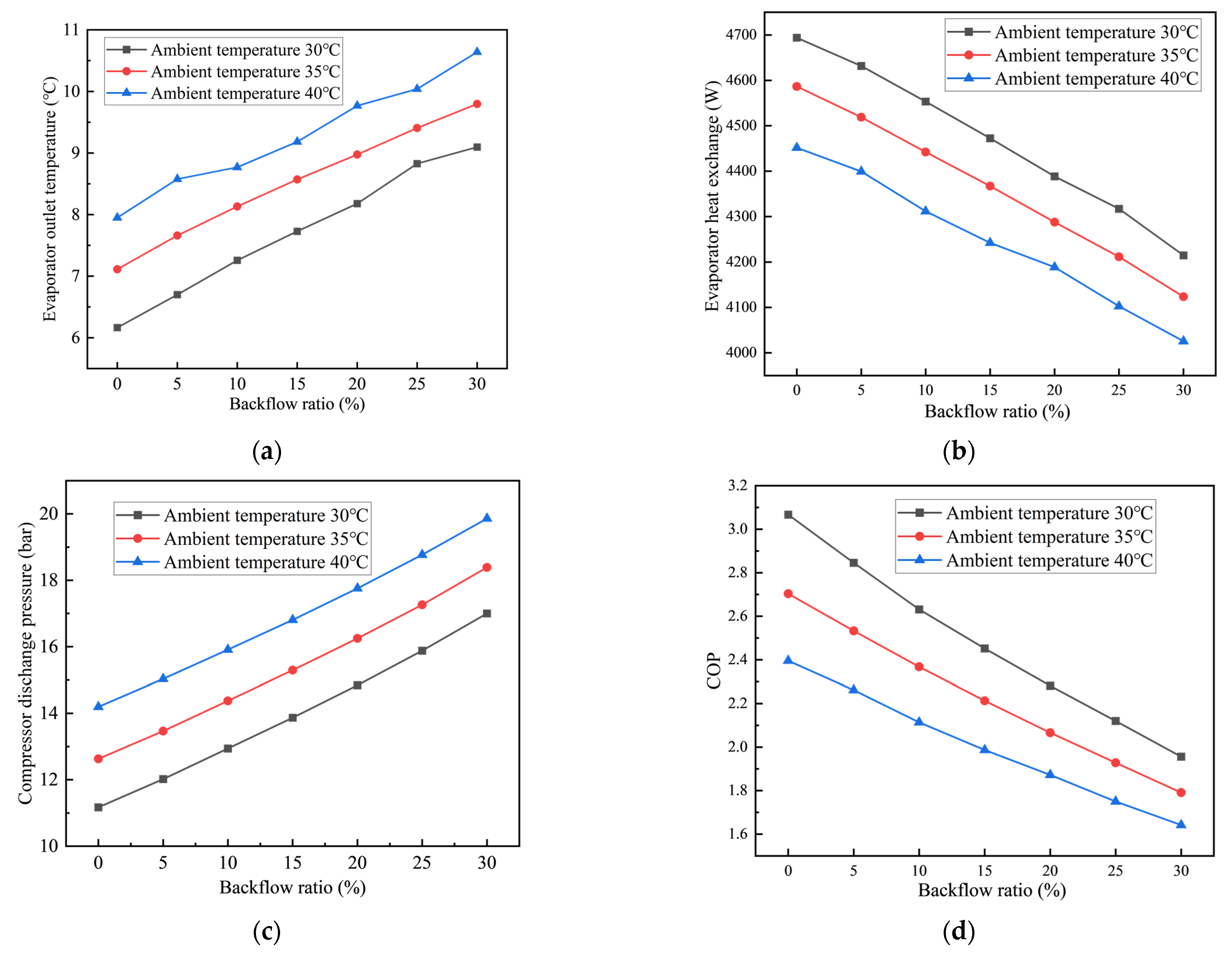
  • The performances of the air conditioning system, including the evaporator outlet temperature, cooling capacity, exhaust pressure of the compressor, and COP, are investigated under different ambient temperatures, air backflow ratios, and air backflow distribution.
  • An optimization model of the underhood is proposed to eliminate the impact of air backflow on the air conditioning system of PHEV.
The rest of the paper is organized as follows. The research method, including the 1D model characterizing the effect of air backflow on the air conditioning system performances, the 3D model characterizing and quantifying the backflow phenomenon in the underhood of PHEV, and experimental test system verifying the air conditioning system performance, is presented in Section 2. The evaluation results, including the impact of the air backflow effect in the underhood of PHEV on the air conditioning system, mechanism analysis of air backflow phenomenon, and performance optimization, are reported in Section 3. Section 4 concludes the paper.

2. Research Method

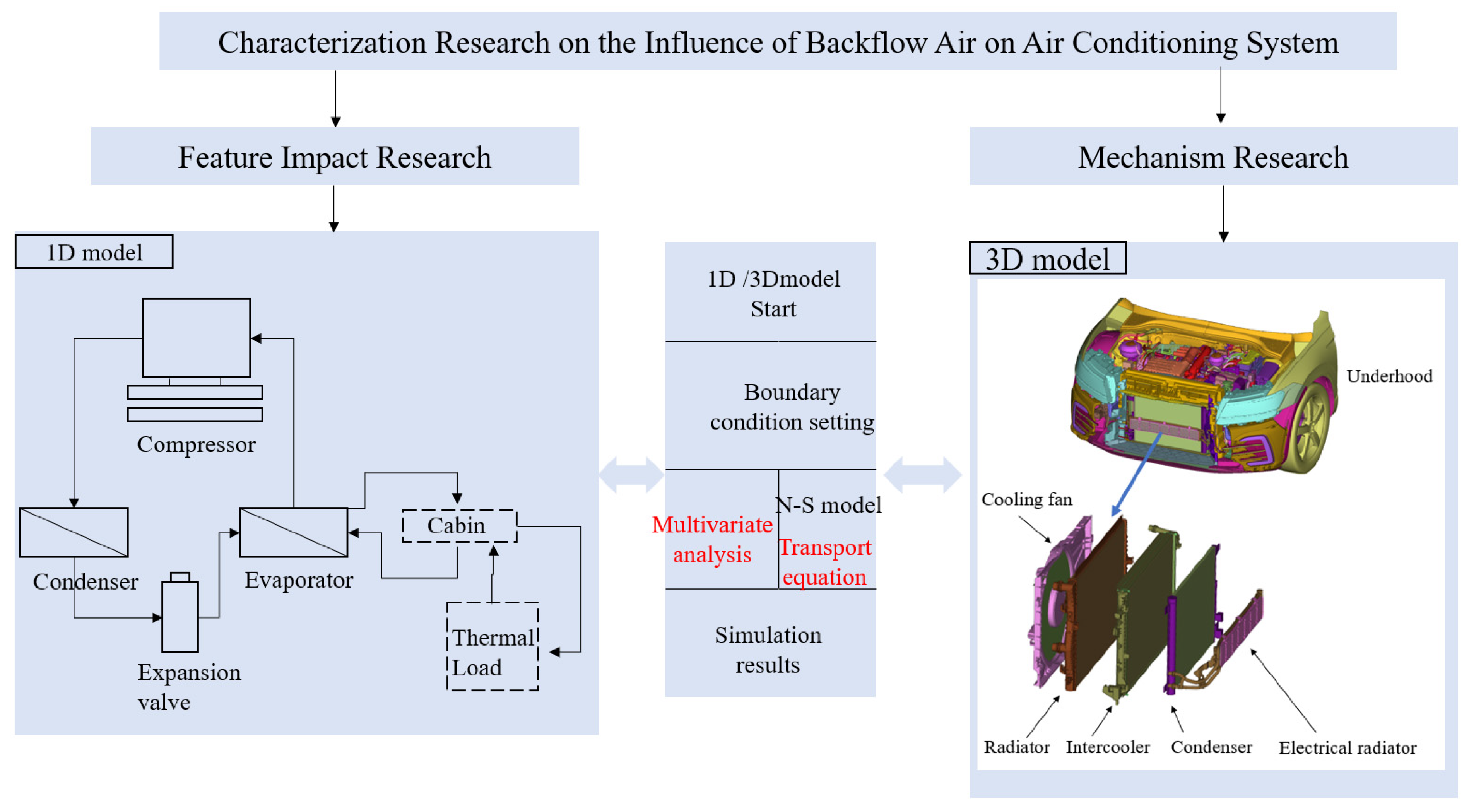
2.1. Research Framework of the Air Backflow Effect in the Underhood

To quantify the backflow phenomenon in the underhood of PHEV and explore the impact of the air backflow in the underhood of PHEV on the air conditioning system, the research framework is constructed in this paper, as shown in Figure 1. The quantification and analysis of the air backflow phenomenon of the underhood of PHEV are realized based on the heat flux marking method demonstrated in this paper. The performances, including the evaporator outlet temperature, cooling capacity, exhaust pressure of compressor, and COP of ACS are investigated under different ambient temperatures, air backflow ratio, and backflow distribution based on one-dimensional simulation. Furthermore, the computational fluid dynamics (CFD) simulation of the underhood can characterize and reflect the air backflow flow field distribution and provide a basis for the structural parameter optimization of the underhood. Moreover, a real vehicle experiment is carried out in order to verify the performance of the air conditioning system after the underhood of PHEV is optimized.

2.2. 1D Model

2.2.1. Compressor

A compressor is the core component of an air conditioning system;, so, the accuracy of its simulation model needs to be much higher than other components. Generally, a 1% error in the compressor simulation model will cause a 0.7% error in the air conditioning system approximately. In this paper, the compressor efficiency model is adopted and the physical model applied to the compressor efficiency model is shown in Equations (1)–(3) [22]:
m c o m = η v V t h r c o m ν s u c
P c o m p = m c o m   ( h d i s h s u c ) / f Q
h d i s = h s u c + h d i s | s h s u c η s
where V t h is the displacement of the compressor, r c o m is the rotary speed of the compressor, m c o m is the mass flow of the compressor, η v is the volumetric efficiency of the compressor, P c o m p is the energy consumption of the compressor, h d i s is the exhaust enthalpy of the compressor, h s u c is the suction enthalpy of the compressor, η s is the isentropic efficiency, h d i s | s is the exhaust enthalpy under the condition of isentropic compression, and f Q is the heat loss of the compressor.

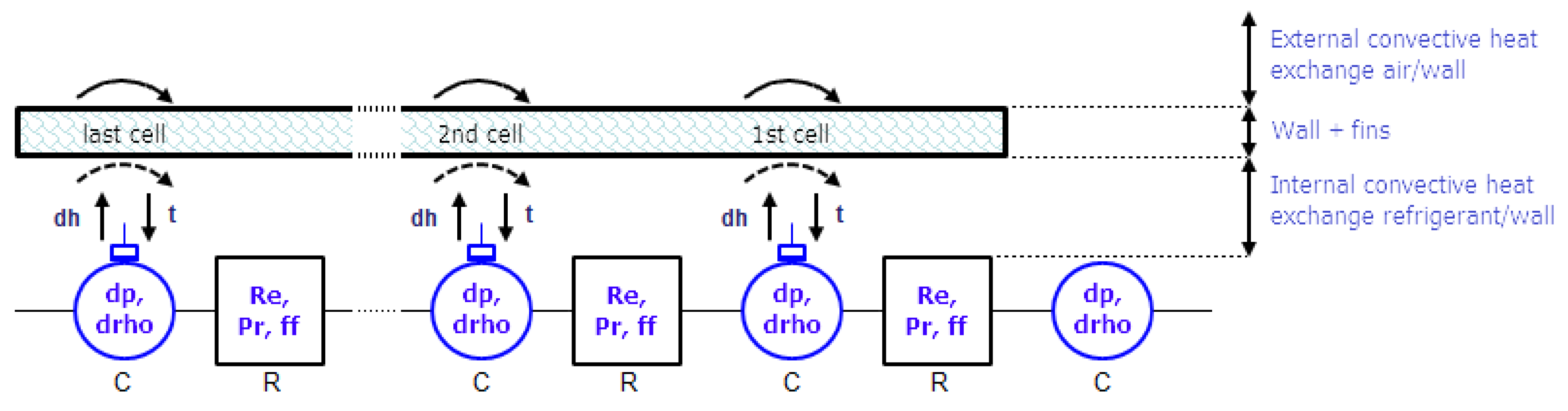
2.2.2. Condenser and Evaporator Model

In this paper, both the condenser and the evaporator of the ACS can be regarded as a model of the microchannel tube–fin heat exchanger; the working principle diagram of the heat exchanger is shown in Figure 2 [23]. The whole heat exchange process includes three parts: external convective heat exchange air–wall, heat conduction wall + fins, and internal convective heat exchange refrigerant–wall. In this model, the heat transfer correlation of the air side of the heat exchange can be expressed as follows [24]:
N u = C 0 × R e N × P r t M
where N u is the Nusselt number; R e is the Reynolds number; P r t is the Prandtl number; and M, N, and C 0 are the parameters that can be used to adjust the heat rejection performance of the heat exchanger.

2.2.3. Expansion Valve

The expansion valve model is used in this paper to achieve different throttling effects by adjusting the opening degree of the expansion valve. The heat loss of the expansion valve is ignored in the model; so, the flow process of the refrigerant in the expansion valve is regarded as a constant enthalpy process. The mass flow rate is calculated as follows:
m e x v = ρ × C q × A × 2 × Δ P ρ
Δ P = P i P O
where m e x v is the mass flow rate, kg/s; ρ is the density, kg / m 3 ; P i is the inlet pressure, barA; P O is the outlet pressure, barA; and C q is the flow coefficient, which can be calculated by Formula (7):
C q = C q m a x × t a n h ( 2 × λ λ c )
where C q m a x is the maximum flow coefficient; λ is the flow number; and λ c is the critical flow number.

2.2.4. Fan and Radiator Model

The cooling fan is located at the front or rear of the radiator to increase the air flow through the radiator and improve the heat dissipation performance of the radiator. In this paper, the performance characteristic parameters of the fan are obtained based on the law of similarity, which mainly include the volumetric flow coefficient and pressure coefficient, and the calculation method is as follows [25]:
ϕ = Q ˙ A f a n V t i p
ψ = Δ P 1 2 ρ V t i p 2
where ϕ is the volumetric flow coefficient; ψ is the pressure coefficient; Q ˙ is the volume flow of air; A f a n is the fan area; and V t i p is the linear velocity of the fan blade tip.
As for the radiator, the heat transfer and flow resistance of the cold side or hot side of the radiator can be calculated by the following formulas:
Δ p = 1 2 K ρ V cool   2
Q rad   = A exch   U ( T in   T out   )
where A exch is the heat exchange area of heat exchanger; ρ is the air density; and K is the pressure loss coefficient.

2.3. 3D Models

2.3.1. Heat Exchanger

To characterize the backflow phenomenon in the underhood of PHEV, it is necessary to perform computational fluid analysis on the cooling module of the underhood. In the cooling module of the underhood, the condenser, intercooler and, radiator all belong to the heat exchanger. In this paper, the heat transfer model of the heat exchanger is established by NTU method, as follows [25]:
N T U = ln ( 1 ε ε C r ) ( C r + 1 )
where Cr is the heat capacity ratio and ε is the effectiveness.
The porous media model is adopted to characterize the pressure loss inside the heat exchanger; it also adopts the correction method of the standard momentum equation, which adds the momentum source term composed of viscous loss term and inertial to the momentum equations. The mathematical description is as follows [22]:
S i = ( j = 1 3 D ij μ u j + j = 1 3 C ij 1 2 ρ | u | u j )
where Si is the source term in the momentum equation, | u | is the velocity scalar, u is the velocity vector, μ is the aerodynamic viscosity, and D and C is the given matrix.
D and C are defined as diagonal matrices, and the formula can be expressed as follows:
S i = ( μ β u i + η 1 2 ρ | u | u i )
where 1 β is the viscous resistance coefficient, and η is the inertial resistance coefficient.
The simplified momentum equation of porous media can be expressed in the form of pressure loss and source term as follows:
Δ P = ( μ Δ n D u i + C 1 1 2 ρ | u | Δ n u i )
The characteristic parameters of the heat exchangers are demonstrated in Table 1:

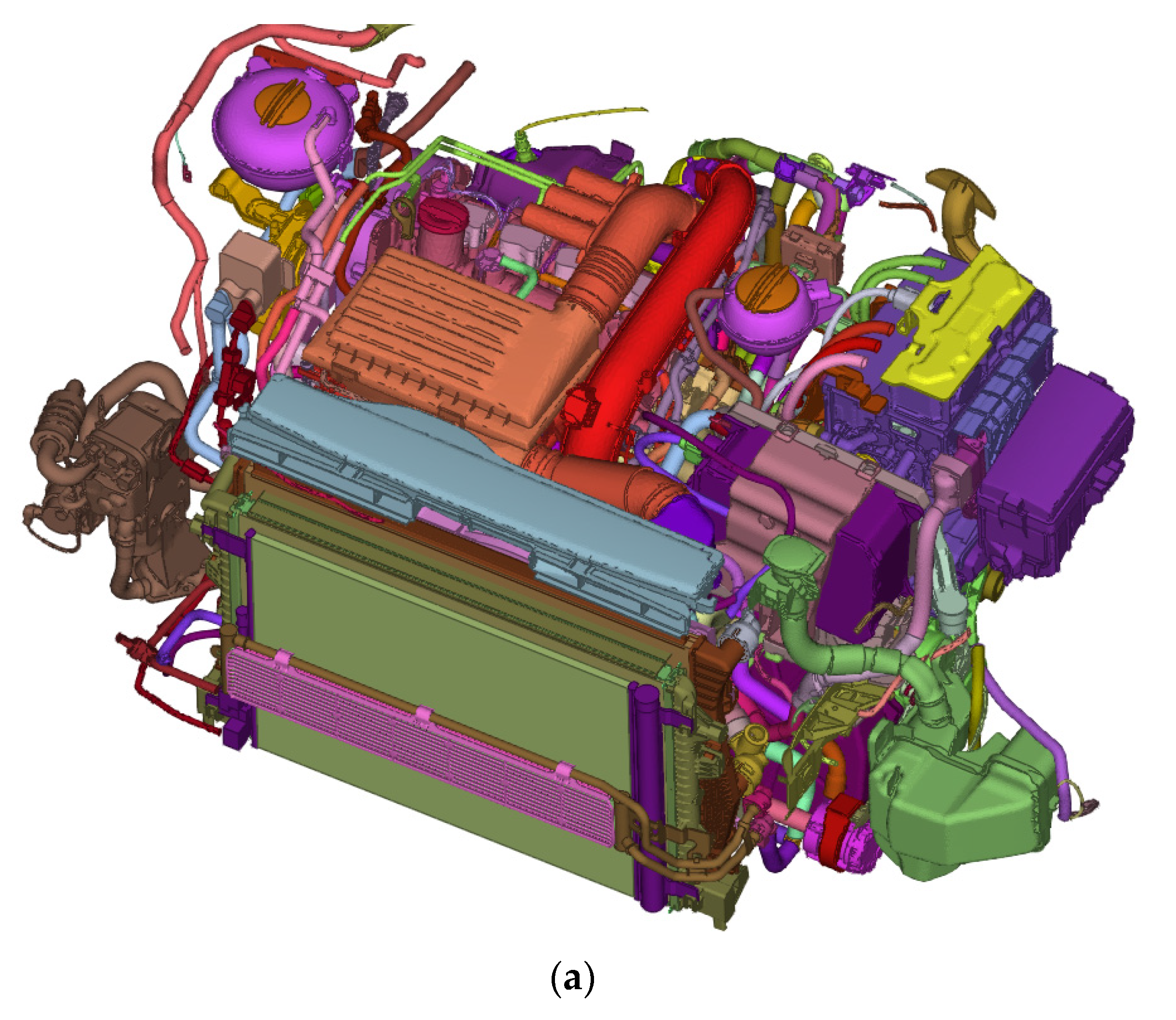
2.3.2. Meshing of the PHEV Underhood

The 3D solid model of the PHEV underhood, including the condenser, radiator, and other components, is shown in Figure 3a. In order to avoid the interference of the airflow disturbance in the limited space on the model accuracy, a rectangular air domain (10 L × 10 W × 6 H) is added, as shown in Figure 3b.
In view of the fact that the air backflow of the underhood is determined in this paper, the front half of the car body surface is also meshed to ensure that the flow details are captured. The mesh model with 80 million mesh is shown in Figure 3c.

2.3.3. Boundary Condition

The air backflow flow field distribution is investigated based on the CFD method. Some boundary conditions should be determined:
(1)
RANS steady-state model is used for steady flow in this model;
(2)
Pressure outlet and velocity inlet are selected for outlet and inlet boundary conditions, respectively;
(3)
The condenser, intercooler, radiator, and electrical radiator are calculated based on the porous media model;
(4)
The cooling fan is simulated based on the multiple reference frame (MRF) method.

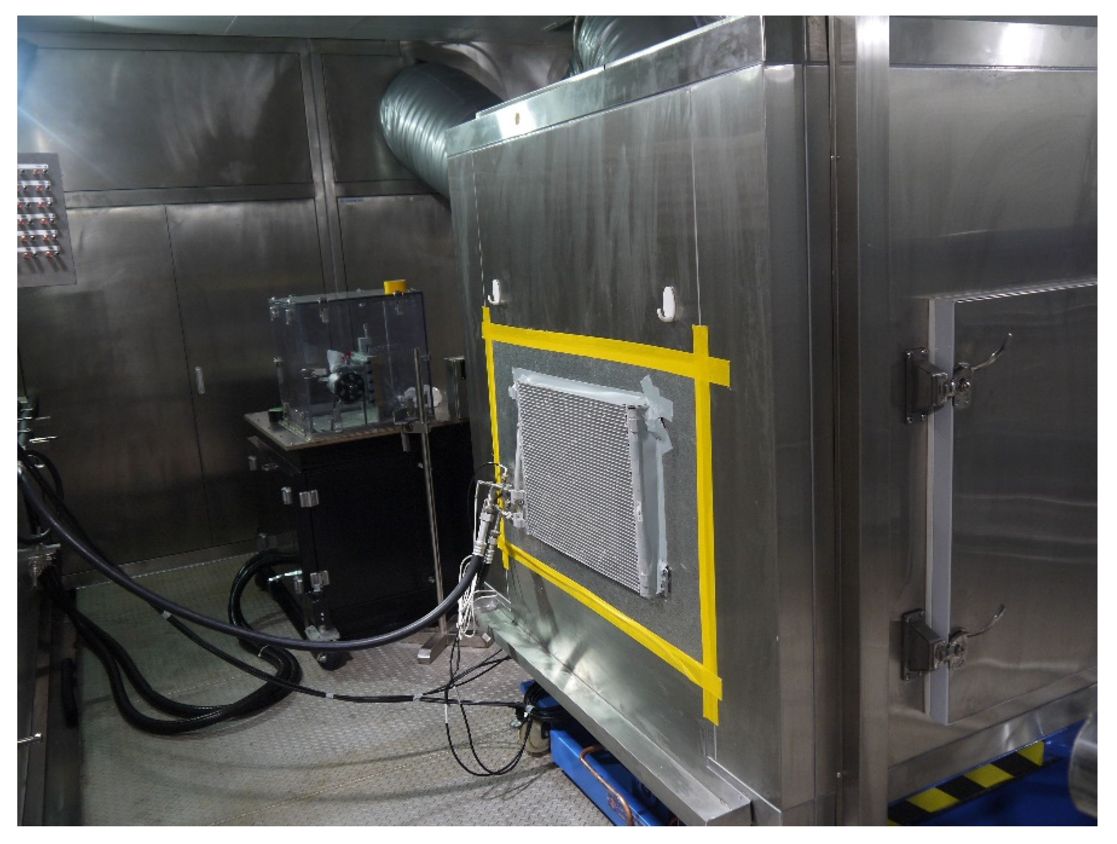
2.4. Experimental Test System

In order to verify the effect of air backflow of the underhood on the cooling capacity of the air conditioning system for PHEV, a system bench experiment is established. The measurement points of the temperature sensor in the cabin are shown in Figure 4, and the cabin temperature value is obtained by calculating the average temperature of multiple measurement points.
In order to ensure more accurate simulation results in the 1D/3D calculation, the relevant key parameters of the condenser, evaporator, and other radiators are obtained through the enthalpy difference experiment. The laboratory is shown in Figure 5.

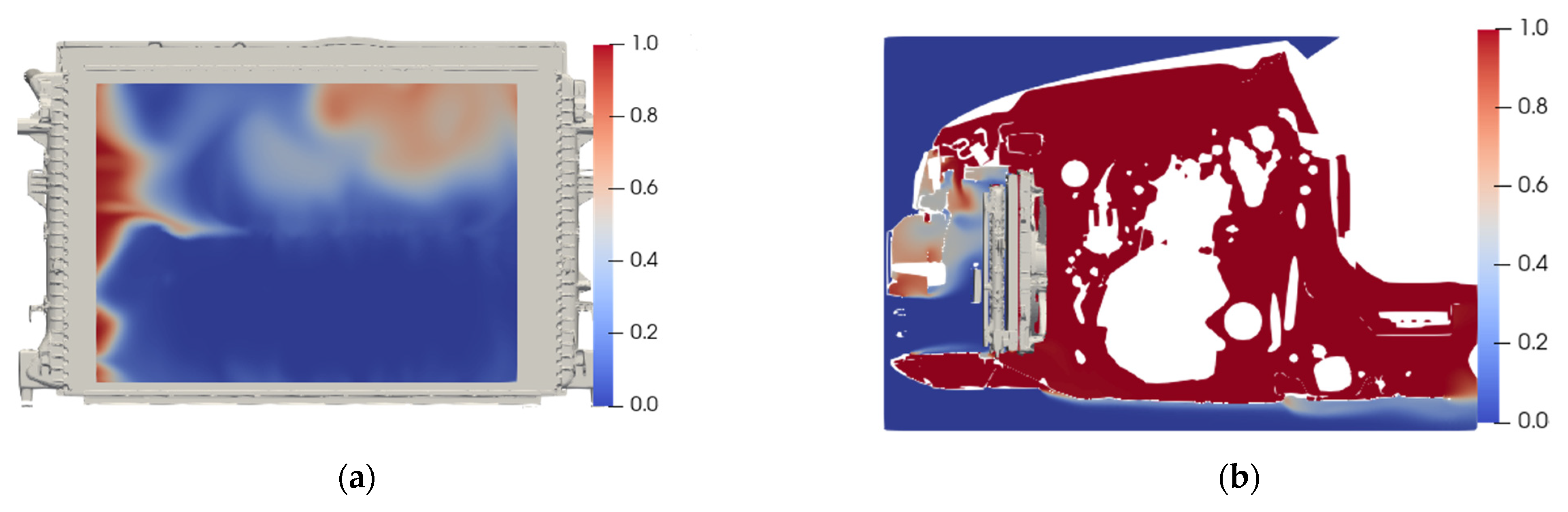
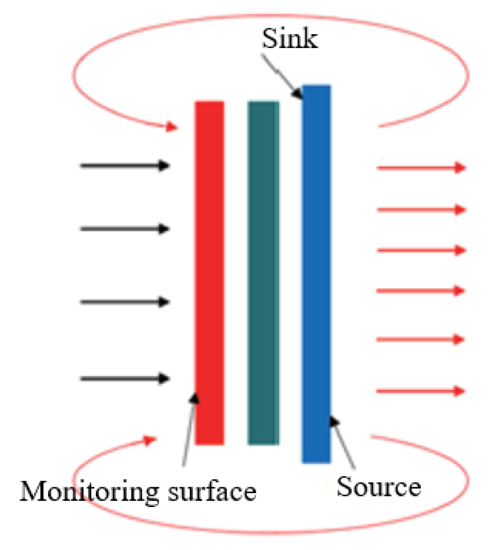
2.5. Heat Flux Marking Method

In order to solve the problem that the air backflow phenomenon of the underhood cannot be judged based on a streamline method, a heat flux marking method is proposed based on the mechanism and distribution of air backflow in the heat exchanger. The air flow passing the heat exchanger will be marked. In order to monitor the backflow air, a monitoring surface will be set at the front end of the heat exchanger. The schematic diagram is shown in Figure 6.
In this paper, in order to quantify the distribution of heated air and calculate the backflow rate, the scalar γ is used to express the proportion of the volume of hot air, referring to the momentum transport equation. The calculation method is as follows:
γ t + u j γ x i = ν 2 γ x j x j ν t γ x j
When the air backflow phenomenon is characterized based on the CFD method, the N-S equation for the entire fluid domain needs to be solved first. Then, the transport equation should be solved after the flow field is in a stable state. Finally, the distribution of hot air in the entire fluid domain can be obtained after the calculation converges.

3. Results and Discussion

In order to systematically analyze the air backflow phenomenon of the underhood of PHEV in this paper, the influence of the air backflow rate on the air conditioning system is explored under different ambient temperatures and backflow distribution. Furthermore, to eliminate the impact of air backflow of the underhood and improve the performance of the thermal management system, the underhood of PHEV is optimized in this paper.

3.1. Effect of Backflow Rate under Different Ambient Temperatures

In this section, the influence of air backflow rate on the air conditioning system is explored under different ambient temperatures. Figure 7 shows that under ambient temperatures of 30 °C, 35 °C, and 40 °C, as the backflow rate increases from 0% to 30%, the air conditioning system performance parameters, including evaporator outlet temperature, evaporator heat exchange, compressor discharge pressure, and COP, are changed accordingly.
As shown in Figure 7, as the air backflow rate of the underhood is increased from 0% to 30%, the heat exchange performance and energy efficiency of the system is reduced. Specifically, when ambient temperature is 30 ℃, the heat exchange of evaporator is reduced from 4693 to 4214 W and the reduction rate is 10.2%, at the same time, while the system COP is reduced from 3.07 to 1.96 and the reduction rate is 36.16%. Thus, more than a 35% improvement of COP could be achieved solely by eliminating air backflow of the underhood of PHEV, which indicates that the decline of the air backflow rate of the underhood enhances the cooling capacity in the air conditioning system. In fact, when the air backflow rate is enhanced, the oncoming air temperature of the condenser will be increased and the heat exchange capacity of the condenser will be decreased, enhancing the condensing pressure and the condensing temperature, thus increasing the discharge pressure of the compressor, as shown in Figure 2(C). Furthermore, when the compressor speed remains unchanged, the suction pressure of the compressor will increase, and the evaporation pressure and evaporation temperature will increase accordingly; thus, the cooling capacity will increase. Moreover, the increase in the suction pressure will cause the compressor power consumption to increase, and the system COP will decrease.

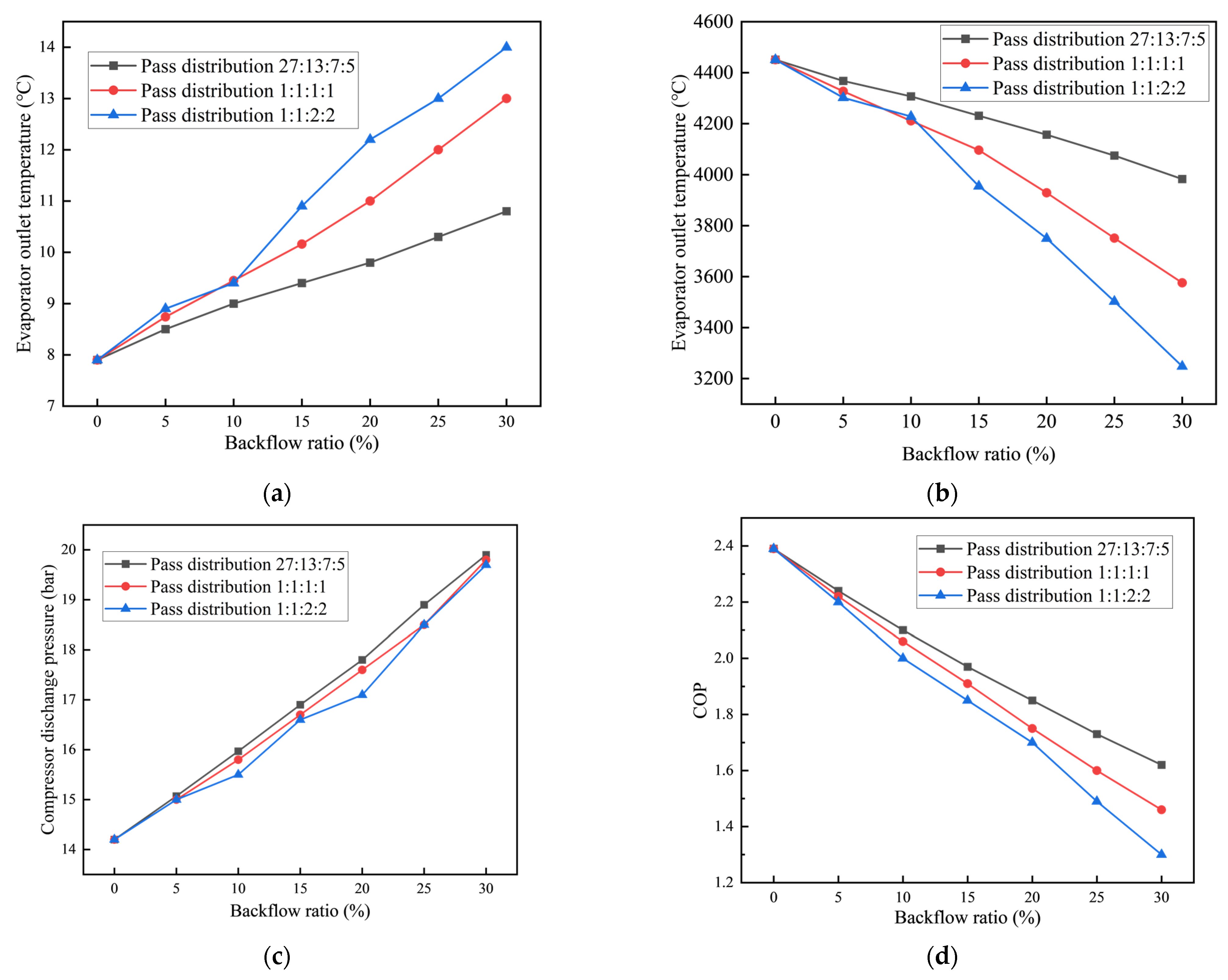
3.2. Effect of Air Backflow Rate under the Different Air Backflow Distribution

In fact, the air backflow phenomenon of the underhood occurs in different local areas of the condenser; thus, the influence of different air backflow distribution on the air conditioning system is analyzed in this section. In view of the fact that the distribution ratio of the cooling tube of the condenser analyzed in this paper is 27:13:7:5, the air backflow distribution form is set according to 27:13:7:5 (uniform distribution), 1:1:1:1, and 1:1:2:2. Figure 8 shows that under different backflow distribution, the air backflow rate has an effect on the performance of the air conditioning system.
As shown in Figure 8, when the air backflow rate is lower than 10%, the air backflow distribution has almost no effect on the performance of air conditioning system. However, when the air backflow rate is higher than 10%, compared to the air backflow concentrated under the condenser (Pass distribution 27:13:7:5) when air backflow is evenly distributed on the surface of the condenser, the cooling capacity of the air conditioning system will be higher and the system efficiency will improve. Specifically, compared to the air backflow concentrated under the condenser, when the air backflow rate is 30% and air backflow is evenly distributed on the surface of the condenser, the heat exchange performance increases from 3248 to 3983 W and the growth rate is 22.6%; at the same time, the system COP increases from 1.3 to 1.62 and the reduction rate is 24.6%, which indicates that the air backflow should be distributed as evenly as possible at the front end of the condenser.

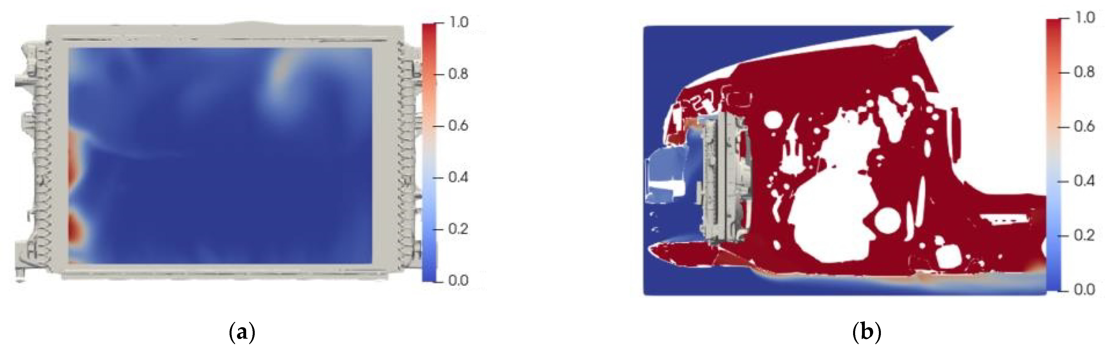
3.3. Mechanism Analysis of Backflow Phenomenon

The analysis in the above section exhibits that the air backflow rate and air backflow distribution of the underhood have a great impact on the performance of the air conditioning system. In order to avoid the impact of air backflow on the air conditioning system of PHEV, the mechanism that causes the backflow phenomenon is analyzed in this section; thus, the performance of the air conditioning system can be optimized in the subsequent section.
The air backflow phenomenon of the underhood is analyzed and the distribution of air backflow on the surface of the condenser is shown in Figure 9.
Figure 9 shows that the distribution of the backflow hot air on the surface of the condenser is mainly concentrated on the left and upper right corners of the condenser. In order to trace the source of backflow hot air, as shown in Figure 9b, most of the backflow hot air is generated by the gap between the radiator and the bracket and the gap between the air guide parts.

3.4. Mechanism Analysis of Air Backflow Phenomenon

In order to eliminate the impact of air backflow on the air conditioning system, a cooling module of the underhood for PHEV is optimized in this section. The optimized structure is shown in the Figure 10. As shown in red in Figure 10, the gap between the radiator and the bracket is sealed and the gap around the air guide is reduced.
Figure 11 shows the optimized results of the PHEV underhood, and that the air backflow phenomenon in the left area is significantly improved and that there only is some backflow hot air around some pores that cannot be sealed.
In order to quantitatively analyze the backflow phenomenon of the optimized structure, the air backflow rate and the mass flow of backflow air are calculated based on the heat flux regression method, and the results are shown in Table 2.
As shown in Table 2, compared with the original structure, the backflow rate of the optimized structure is reduced from 32.7% to 9.3%, the backflow air in the left area is significantly reduced, and the backflow air mass flow is reduced from 0.169 kg/s to 0.048 kg/s. The reduction rate is 36.16% and the backflow situation of underhood cooling module is significantly improved.
In order to verify results of the optimization, the performance of the air conditioning system installed with the original cooling module and the optimized cooling structure is tested in a real vehicle under driving conditions of 32 km/h. The performance results of the air conditioning system are shown in Figure 12.
As shown in Figure 12, when the air backflow phenomenon is weakened, the cooling capacity of the air conditioning system is significantly better. Compared with the original underhood cooling structure, the cabin temperature can be reduced by 3–5 °C.

4. Conclusions

The air backflow phenomenon of the PHEV underhood is quantitatively investigated in this paper and the relevant conclusions are as follows:
(1)
The heat flux marking method proposed in this paper can accurately quantify the backflow phenomenon in the underhood of PHEV based on the momentum transport equation.
(2)
The decrease in the air backflow rate of the underhood helps to improve the refrigeration capacity of the air conditioning system, thereby increasing the COP of the system
(3)
When the air backflow ratio cannot be reduced below 10%, the air backflow should be distributed as evenly as possible at the front end of the condenser.
(4)
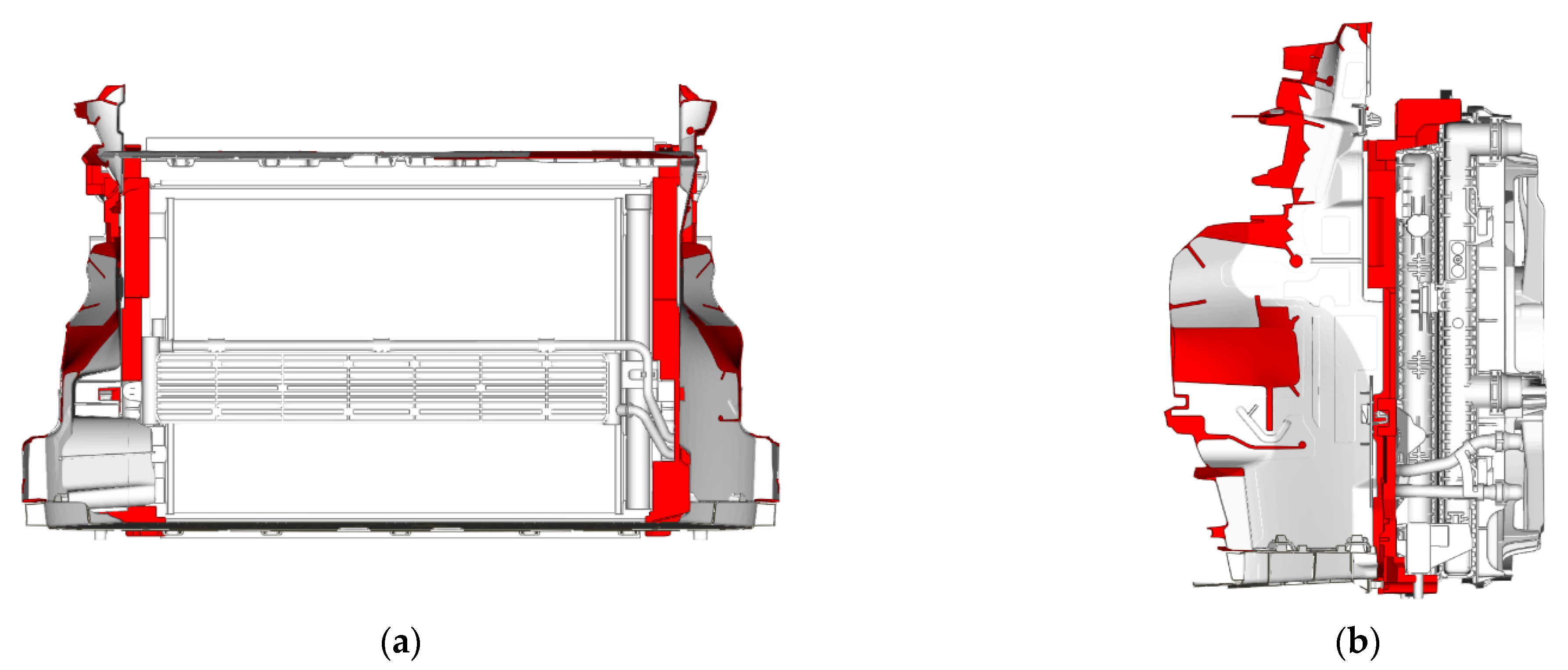
In order to eliminate the impact of air backflow on the PHEV underhood, the gap between the radiator and the bracket is sealed and the gap around the air guide is reduced. Compared with the original structure, the air backflow rate of the optimized structure is reduced from 32.7% to 9.3% and the cabin temperature can be reduced by 3–5 °C.
In order to further investigate the effect of backflow phenomenon of the underhood on air conditioning system, digital twin technology should be considered in the future so that backflow phenomenon can be investigated in an all-round way without a large number of time-consuming and high-cost experiments and simulations.

Author Contributions

Funding acquisition, S.X.; investigation, H.W. and X.T.; methodology, H.W.; project administration, S.X.; visualization, J.Z.; writing—original draft, H.W.; writing—review and editing, X.T. All authors have read and agreed to the published version of the manuscript.

Funding

The authors wish to acknowledge for the financial support from the National Natural Science Foundation of China Grant No. 21776221, for the work reported in this paper.

Institutional Review Board Statement

Not applicable.

Informed Consent Statement

Not applicable.

Data Availability Statement

Not applicable.

Conflicts of Interest

The authors declare that they have no known competing financial interests or personal relationships that could have appeared to influence the work reported in this paper.

Nomenclature

PHEVplug-in hybrid electric vehicles
ACSair conditioning system
ICEinternal combustion engine
UDDSurban dynamometer driving schedule
CFDcomputational fluid dynamics
EMSenergy management strategy
COPcoefficient of performance
BTMSbattery thermal management system
MTMSmotor thermal management system
Acronyms
V t h displacement of the compressor
m c o m mass flow of the compressor
P c o m p energy consumption of the compressor
h s u c suction enthalpy of the compressor
h d i s | s exhaust enthalpy under the condition of isentropic compression
ρ density
η inertial resistance coefficient
γvolume proportion of the hot air
ϕ volumetric flow coefficient
N u Nusselt number
P r t Prandtl number
V t i p linear velocity of the fan blade tip
r c o m rotary speed of the compressor
η v volumetric efficiency of the compressor
h d i s exhaust enthalpy of the compressor
η s isentropic efficiency
f Q heat loss of compressor
u velocity vector
1 β viscous resistance coefficient
C r heat capacity ratio
R e Reynold number
Q ˙ volume flow of air
A f a n Fan Area

References

  1. Solmaz, H.; Ardebili, S.; Calam, A.; Yılmaz, E.; İpci, D. Prediction of Performance and Exhaust Emissions of a CI Engine Fueled with Multi-Wall Carbon Nanotube Doped Biodiesel-Diesel Blends Using Response Surface Method. Energy 2021, 227, 120518. [Google Scholar] [CrossRef]
  2. Geng, L.; Xiao, Y.; Li, S.; Chen, H.; Chen, X. Effects of injection timing and rail pressure on particulate size-number distribution of a common rail DI engine fueled with fischer-tropsch diesel synthesized from coal. J. Energy Inst. 2021, 95, 219–230. [Google Scholar] [CrossRef]
  3. Liu, J.; Wu, P.; Sun, P.; Ji, Q.; Zhang, Q.; Wang, P. Effects of iron-based fuel borne catalyst addition on combustion, in-cylinder soot distribution and exhaust emission characteristics in a common-rail diesel engine. Fuel 2021, 290, 120096. [Google Scholar] [CrossRef]
  4. Zhang, Y.; Yuan, X.; Duan, L.; Xu, Y.; Lan, F. Environmental temperature effects on the energy flow of plug-in hybrid electric vehicles. J. Power Sources 2021, 506, 230231. [Google Scholar] [CrossRef]
  5. Mahmoodi-k, M.; Montazeri, M.; Madanipour, V. Simultaneous multi-objective optimization of a PHEV power management system and component sizing in real world traffic condition. Energy 2021, 233, 121111. [Google Scholar] [CrossRef]
  6. Aljehane, N.; Mansour, R. Optimal allocation of renewable energy source and charging station for PHEVs. Sustain. Energy Technol. Assess. 2021, 49, 101669. [Google Scholar] [CrossRef]
  7. Böhme, T.; Frank, B. Hybrid Systems, Optimal Control and Hybrid Vehicles; Springer: Berlin/Heidelberg, Germany, 2017. [Google Scholar]
  8. Hemmati, S.; Doshi, N.; Hanover, D.; Morgan, C.; Shahbakhti, M. Integrated cabin heating and powertrain thermal energy management for a connected hybrid electric vehicle. Appl. Energy 2021, 283, 116353. [Google Scholar] [CrossRef]
  9. Liu, J.; Chen, Y.; Li, W.; Shang, F.; Zhan, J. Hybrid-Trip-Model-Based Energy Management of a PHEV with Computation-Optimized Dynamic Programming. IEEE Trans. Veh. Technol. 2018, 67, 338–353. [Google Scholar] [CrossRef]
  10. Fan Li Zhang, Y.; Dou, H.; Zou, R. Design of an integrated energy management strategy for a plug-in hybrid electric bus. J. Power Sources 2019, 448, 227391. [Google Scholar] [CrossRef]
  11. Chen, Z.; Xiong, R.; Cao, J. Particle swarm optimization-based optimal power management of plug-in hybrid electric vehicles considering uncertain driving conditions. Energy 2016, 96, 197–208. [Google Scholar] [CrossRef]
  12. Liu, T.; Hu, X.; Li, S.; Cao, D. Reinforcement Learning Optimized Look-Ahead Energy Management of a Parallel Hybrid Electric Vehicle. IEEE Trans. Mechatron. 2017, 22, 1497–1507. [Google Scholar] [CrossRef]
  13. Peng, J.; He, H.; Xiong, R. Rule based energy management strategy for a series-parallel plug-in hybrid electric bus optimized by dynamic programming. Appl. Energy 2017, 185, 1633–1643. [Google Scholar] [CrossRef]
  14. Song, P.; Lei, Y.; Fu, Y. Multi-objective optimization and matching of power source for PHEV based on genetic algorithm. Energies 2020, 13, 1127. [Google Scholar] [CrossRef] [Green Version]
  15. Ribau, J.; Sousa, J.; Silva, C. Multi-Objective Optimization of Fuel Cell Hybrid Vehicle Powertrain Design—Cost and Energy; SAE Technical Paper; SAE: Detroit, MI, USA, 2013. [Google Scholar] [CrossRef]
  16. Qi, X.; Wu, G.; Boriboonsomsin, K.; Barth, M.J. Development and evaluation of an evolutionary algorithm-based online energy management system for plug-in hybrid electric vehicles. IEEE Trans. Intell. Transp. Syst. 2017, 18, 2181–2191. [Google Scholar] [CrossRef]
  17. Silva, S.; Eckert, J.; Silva, F.; Silva, L.; Dedini, F. Multi-objective optimization design and control of plug-in hybrid electric vehicle powertrain for minimization of energy consumption, exhaust emissions and battery degradation. Energy Convers. Manag. 2021, 234, 113909. [Google Scholar] [CrossRef]
  18. Pan, L.; Liu, C.; Zhang, Z.; Wang, T.; Shi, J.; Chen, J. Energy-saving effect of utilizing recirculated air in electric vehicle air conditioning system. Int. J. Refrig. 2019, 12, 122–129. [Google Scholar] [CrossRef]
  19. Zhang, Z.; Liu, C.; Chen, X.; Zhang, C.; Chen, J. Annual energy consumption of electric vehicle air conditioning in China. Appl. Therm. Eng. 2017, 125, 567–574. [Google Scholar] [CrossRef]
  20. Oh, M.; Ahn, J.; Kim, D.; Jang, D.; Kim, Y. Thermal comfort and energy saving in a vehicle compartment using a localized air-conditioning system. Appl. Energy 2014, 133, 14–21. [Google Scholar] [CrossRef]
  21. Jeffers, M.; Chaney, L.; Rugh, J. Climate Control Load Reduction Strategies for Electric Drive Vehicles in Warm Weather; SAE Technical Paper; SAE: Detroit, MI, USA, 2015. [Google Scholar] [CrossRef] [Green Version]
  22. Liu, Y.; Gao, Q.; Zhang, T.; Cui, C.; Jin, S. Exploration of interactive thermal influence characteristics of power and air conditioning system based on 1D/3D coupling calculation in electric vehicle underhood. Appl. Therm. Eng. 2020, 167, 114717. [Google Scholar] [CrossRef]
  23. Hofstadtera, R.; Jorge, A.; Kozek, M. Energy optimal control of thermal comfort in trams. Appl. Therm. Eng. 2018, 143, 812–821. [Google Scholar] [CrossRef]
  24. Collier, J.; Thome, J. Convective Boiling and Condensation, 3rd ed.; Oxford University Press: Oxford, UK.
  25. Shen, M.; Gao, Q. System simulation on refrigerant-based battery thermal management technology for electric vehicles. Energy Convers. Manag. 2020, 203, 112176. [Google Scholar] [CrossRef]
Figure 1. Research framework of the air backflow effect in the underhood of PHEV.
Energies 15 03183 g001
Figure 2. Diagram of discrete cell of the condenser component.
Energies 15 03183 g002
Figure 3. The 3D model of the underhood for PHEV. (a) A 3D solid model of the underhood; (b) the CFD calculation domain of the underhood for PHEV; (c) the mesh of the underhood for PHEV.
Energies 15 03183 g003aEnergies 15 03183 g003b
Figure 4. The measurement points of temperature sensor in the cabin. (a) Side air outlet; (b) Middle air outlet; (c) Front seat passenger; (d) Rear seat passenger; (e) Dashboard area; (f) Cabin bottom.
Energies 15 03183 g004
Figure 5. The heat exchanger performance test platform.
Energies 15 03183 g005
Figure 6. Schematic diagram of air backflow calculation method.
Energies 15 03183 g006
Figure 7. Influences of backflow rate on air conditioning performances under different ambient temperatures. (a) Evaporator outlet temperature; (b) evaporator heat rejection; (c) compressor discharge pressure; and (d) COP.
Energies 15 03183 g007
Figure 8. Influences of the backflow rate on air conditioning performances under different ambient temperatures. (a) Evaporator exit temperature; (b) evaporator heat rejection; (c) discharge pressure; and (d) COP.
Energies 15 03183 g008
Figure 9. Backflow air distribution of original structure. (a) Backflow air distribution front view; (b) backflow air distribution side view.
Energies 15 03183 g009
Figure 10. Optimized cooling module of PHEV. (a) Optimized structure front view; (b) optimized structure side view.
Energies 15 03183 g010
Figure 11. Backflow air distribution of optimized structure. (a) Optimized structure front view; (b) optimized structure side view.
Energies 15 03183 g011
Figure 12. HVAC performances after reflux optimization.
Energies 15 03183 g012
Table 1. The viscous resistance coefficient and inertial resistance coefficient of heat exchangers.
Heat ExchangerViscous Resistance
Coefficient (m−2)
Inertial Resistance
Coefficient (m−1)
Radiator1192.5160.1
Intercooler813.674.5
Condenser851.8126.9
Electrical radiator808.2114.3
Table 2. Comparison of the backflow rate of the optimized cooling module and the original structure.
Air Mass Flow (kg/s)Backflow Ratio (%)Backflow Air Mass Flow (kg/s)
Original Structure0.51832.70.169
Optimized structure0.5189.30.048
Publisher’s Note: MDPI stays neutral with regard to jurisdictional claims in published maps and institutional affiliations.

