Article

Determining the Stability of a Mobile Manipulator for the Transport and Assembly of Arches in the Yielding Arch Support

1
Faculty of Mechanical Engineering and Robotics, AGH University of Science and Technology, al. Mickiewicz 30, 30-059 Kraków, Poland
2
Faculty of Electrical Engineering, Automatics, Computer Science and Biomedical Engineering, AGH University of Science and Technology, al. Mickiewicz 30, 30-059 Kraków, Poland
3
FAMA Sp. z.o.o., ul. Przemysłowa 1, 83-140 Gniew, Poland
*
Author to whom correspondence should be addressed.
Energies 2022, 15(9), 3170; https://doi.org/10.3390/en15093170
Submission received: 18 March 2022 / Revised: 19 April 2022 / Accepted: 21 April 2022 / Published: 26 April 2022
(This article belongs to the Special Issue Volume II: Mining Innovation)

Abstract

:
The yielding arch support is transported and installed in the face with the use of auxiliary machines. These activities in underground mining cause many problems, which have as yet not been solved. Currently, transport and assembly are carried out manually, using the roadheader and suspended rail, or various types of mounting platforms. The analysis of the structure of the existing solutions resulted in the development of an original structure that met the requirements of Polish mines. Developed jointly by FAMA Sp. z o.o. and the AGH University of Science and Technology in Krakow, Poland, the mining modular transport and assembly unit (MZT-M) will enable the transport and assembly of support arches in the mining face. Additionally, it can also be used to reload works, which is related to the work ergonomics in underground coal mining, which is the main energy resource in Poland. The most important problem to be solved in the case of this manipulator, due to the limited space in the excavation, is how to ensure its stability during various phases of its operation. Therefore, analyses were carried out to find a solution, which resulted in determining specific conditions and design requirements related to the operation of this manipulator.

1. Introduction

In hard coal mines, one of the key processes is tunnelling. During tunnelling and later during the exploitation of such an excavation, it is deformed due to the pressure of the rock mass [1,2]. The floor may be deformed [3,4], but the more serious danger is caused by the roof deformation [5,6,7]. Hence, various types of support for tunnels are used [8,9,10,11], but the most commonly used in hard coal mines are yielding arch support frames [12,13,14].
The use of yielding arch support frames in galleries of underground mines involves installing their elements in the face using a roadheader [15,16]. For this purpose, apart from the aforementioned roadheader, a suspended monorail [17] and moving equipment are used. It is easy to notice that this process, i.e., the transport of support arches and other elements of the support, the lining, as well as the assembly itself, is performed manually. Delivering the support elements to the face is particularly cumbersome and requires a lot of physical effort. Hence, an idea arose to use a device enabling the transfer of elements of the support frame from the place of their storage to the face, in front of the roadheader, and to deliver them to the place of assembly [18,19,20].
The current solutions do not enable one to perform the above-mentioned functions due to the dimensions of the excavation. This is clearly visible in the attached photo (Figure 1), where the manipulator is attached to the platform. Examples of such solutions are GTA [21] and Deilmann–Haniel Mining Systems GmbH [22] platforms. However, in this situation, it is not possible for the platform to ride over the roadheader (Figure 2).
A conceptual diagram of the manipulator, consisting of a boom mounted on one runway beam with a stabilizing foot and a hydraulic power unit, and consisting separately of a haulage drive (haulage unit) moving along the suspended monorail track, is shown in Figure 3a [19,20].
A characteristic feature of this solution is the asymmetrical mounting of the suspended monorail in the gallery and the need to stabilize (balance) the modular transport and assembly unit (MZT-M) during the transport of support elements, whereas the manipulator can only be operated when the stabilizing foot is unfolded.
Bearing in mind the above, the following assumptions were formulated:
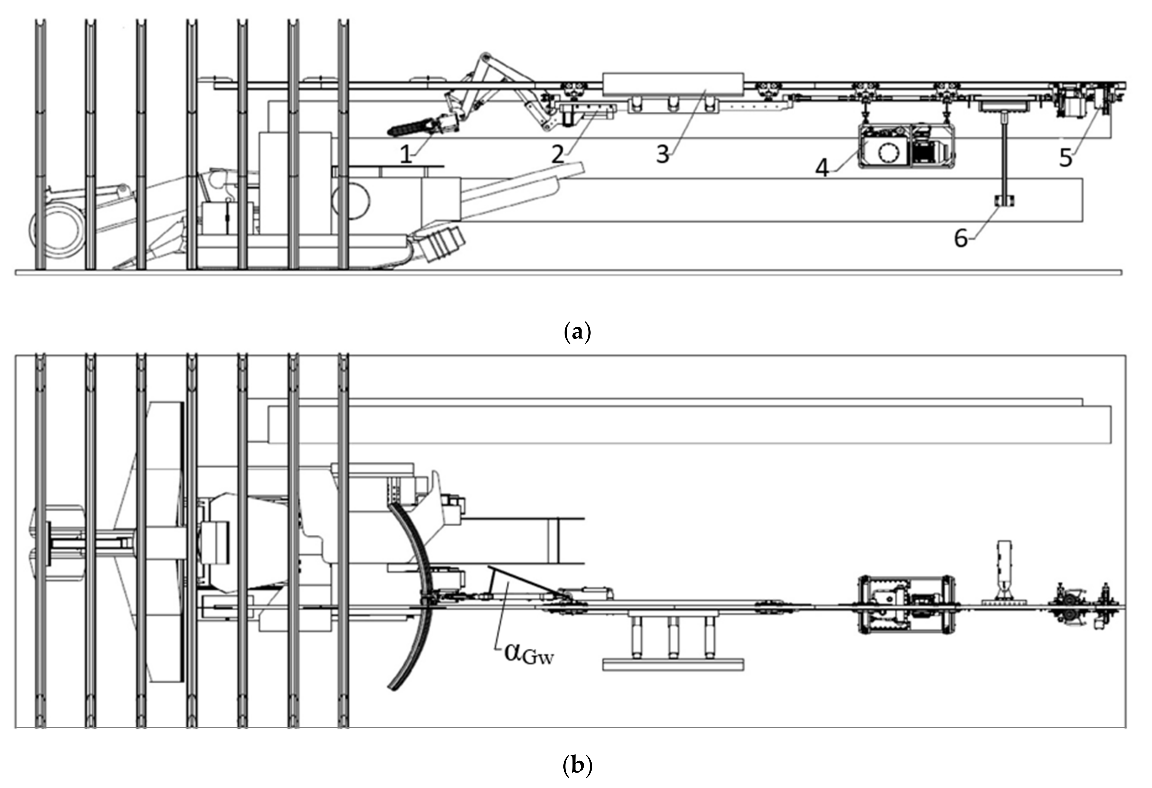
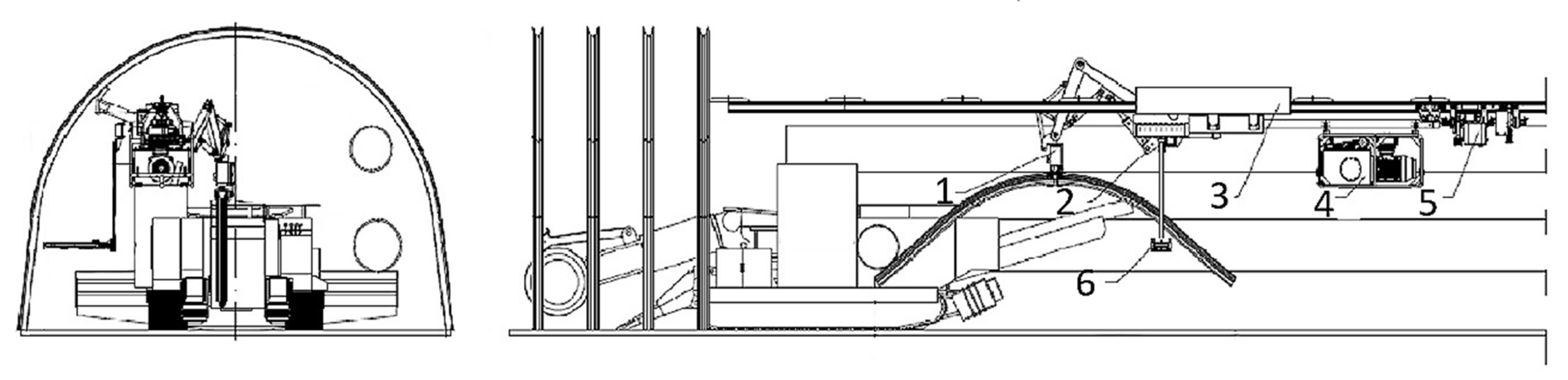
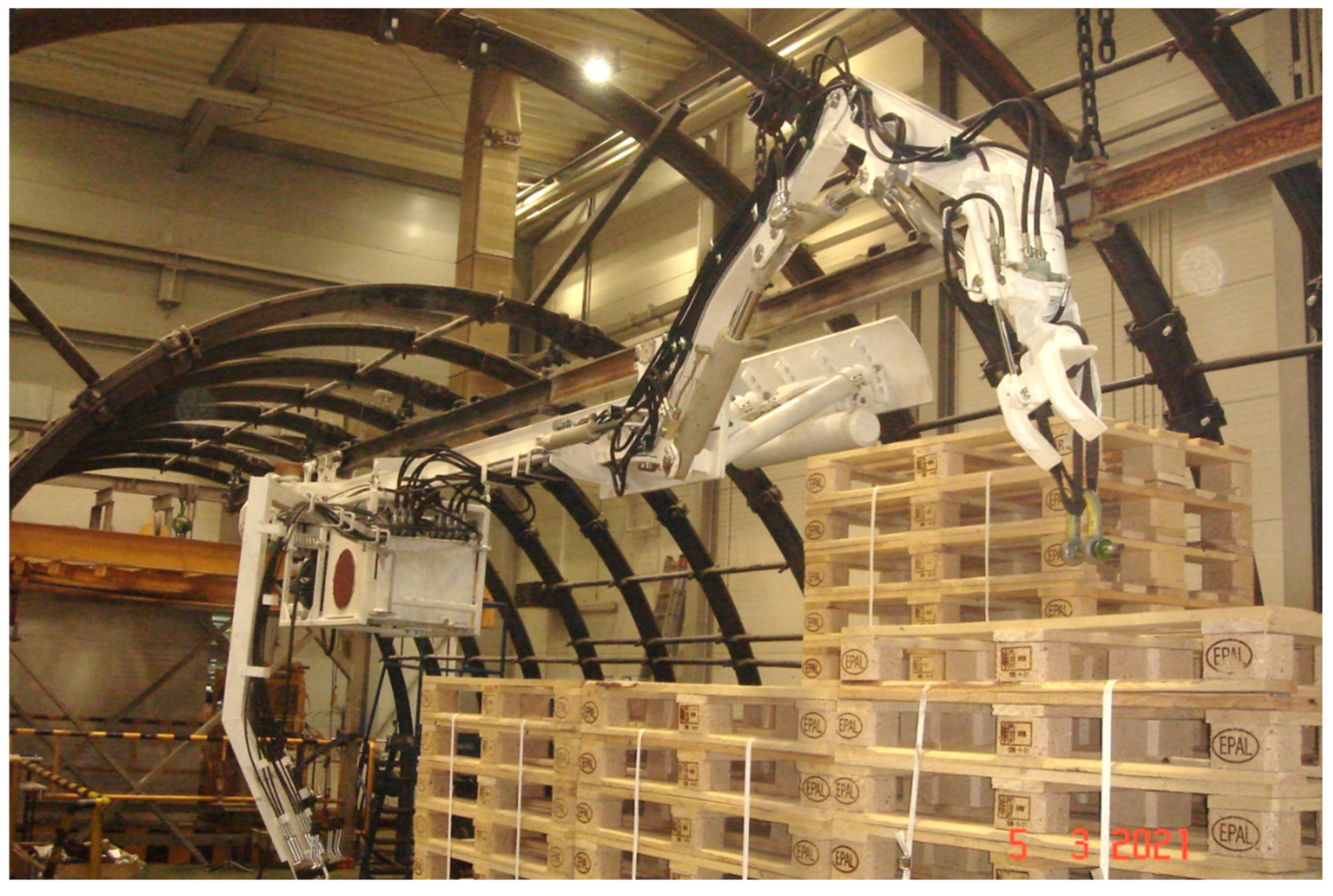
  • the manipulator with a boom and its drive mounted on one monorail with a useful weight of up to 440 kg or without it in the transport position (boom raised, folded, twisted) can be moved without the possibility of maneuvering at the same time only when the stabilizing foot is folded;
  • the maneuvering of the boom itself, with or without a load, is possible only after stoppage, with the use of a stabilizing foot stretched against the yielding support arches.
Therefore, the manipulator balancing process was performed for a transport position with a permissible boom rotation with an angle αGw ≤ 30° (Figure 3b and Figure 4). The model of the boom with its individual elements marked is shown in Figure 5.
The article’s main objective is to present the process of analytically determining the stability of the manipulator during various phases of its operation and to determine the counterweight mass for the boom in the transport position. A solution was searched for, resulting in specific conditions and design requirements related to the operation of this manipulator being obtained and specified.

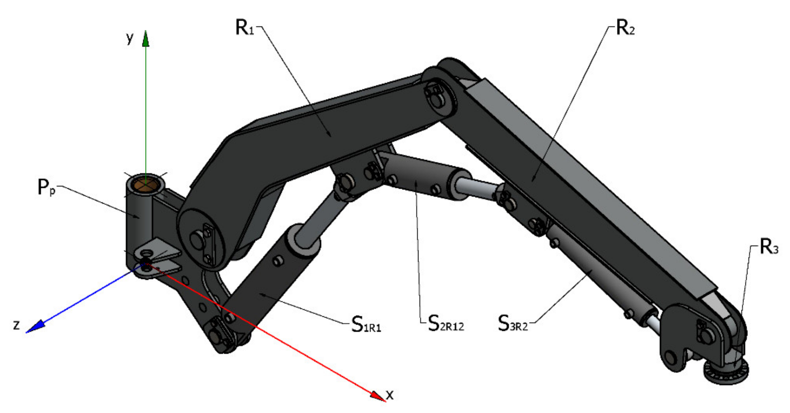
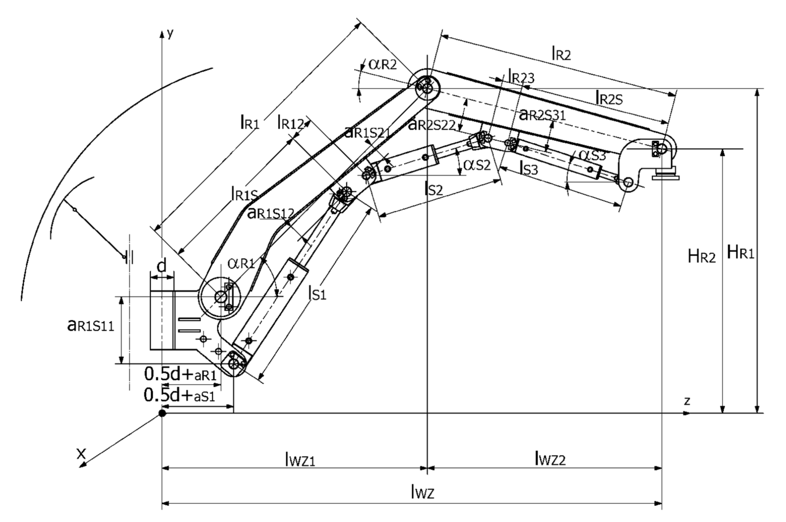
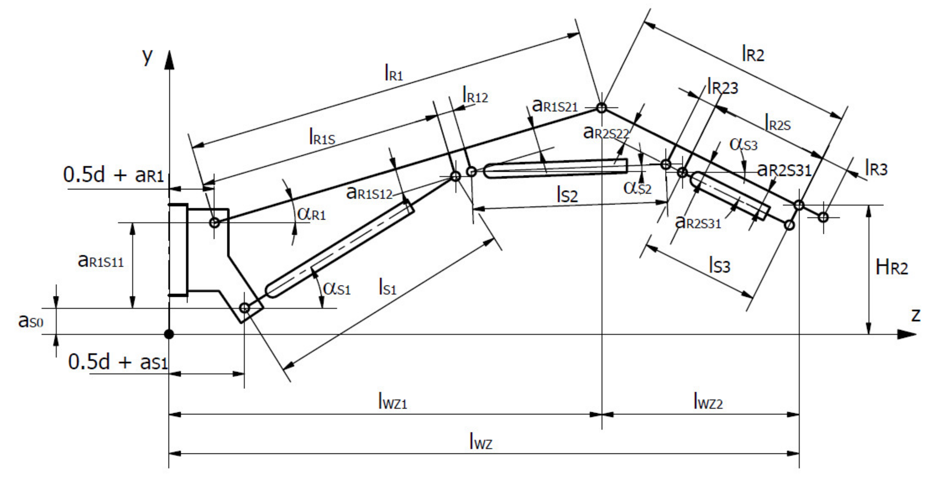
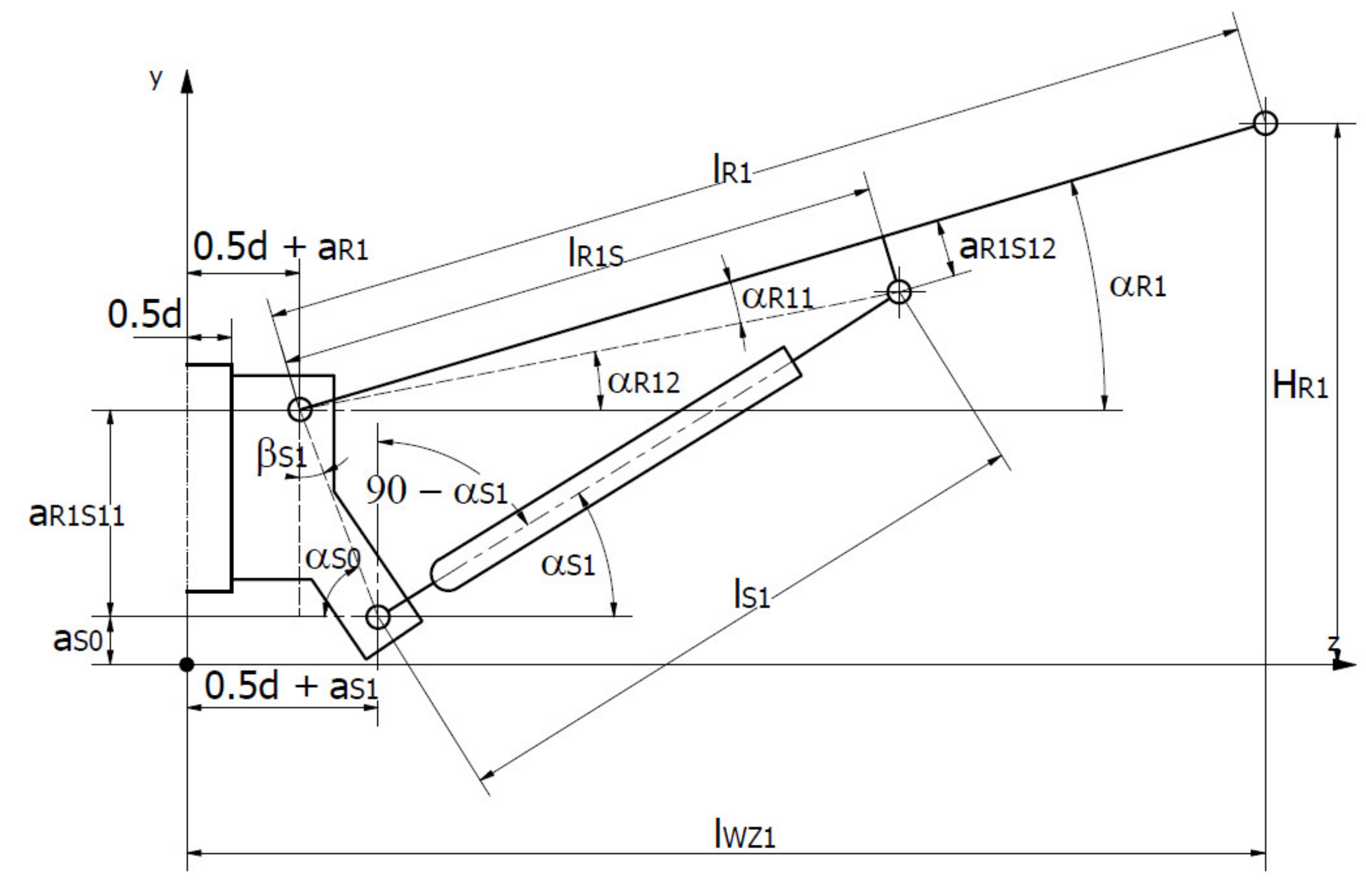
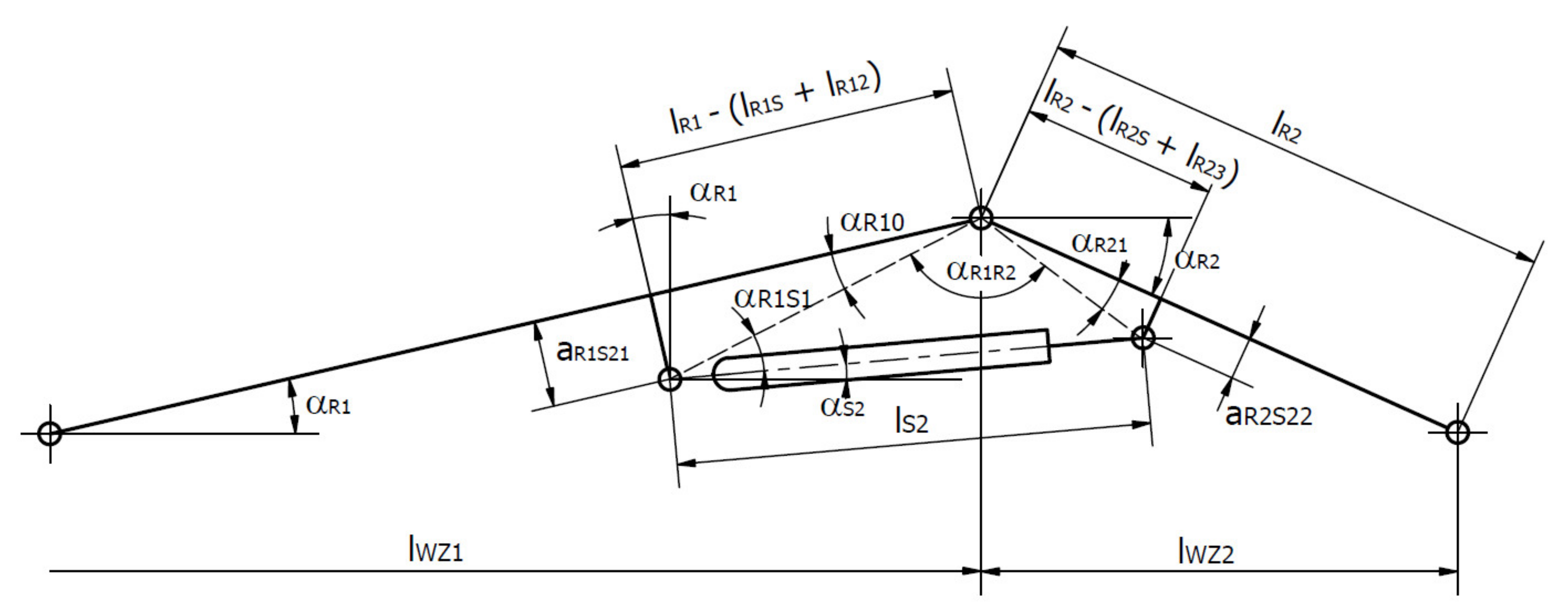
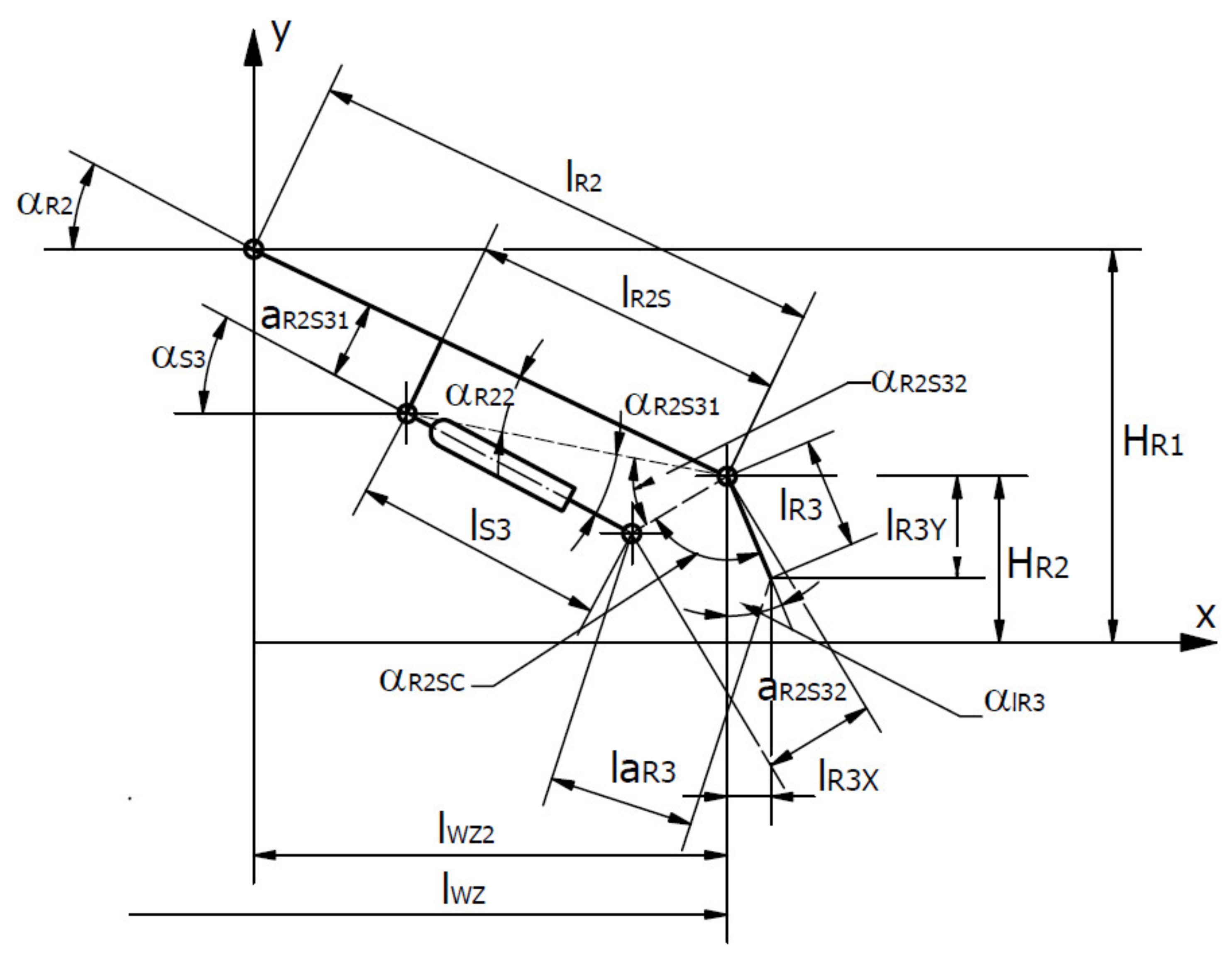
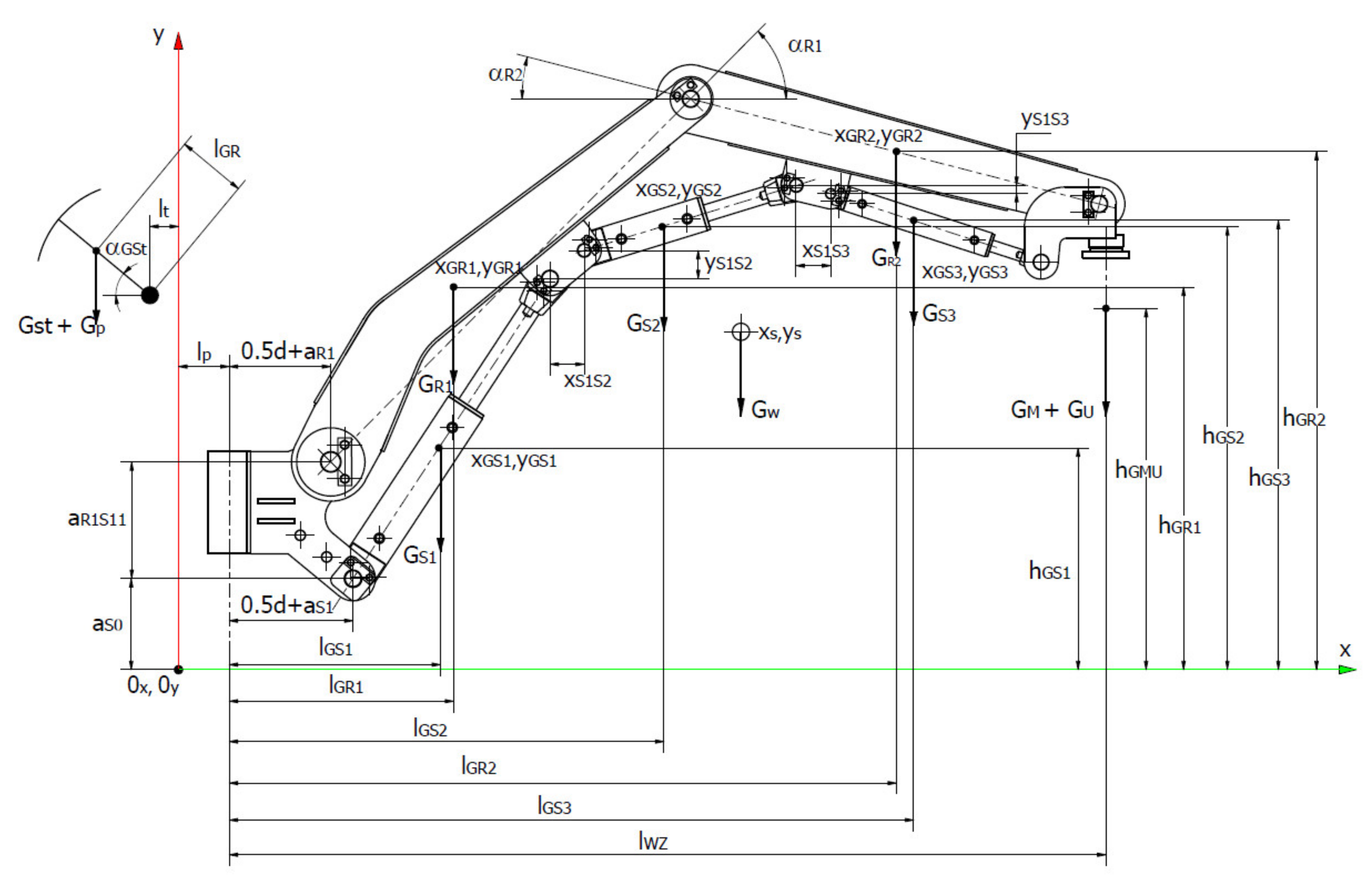
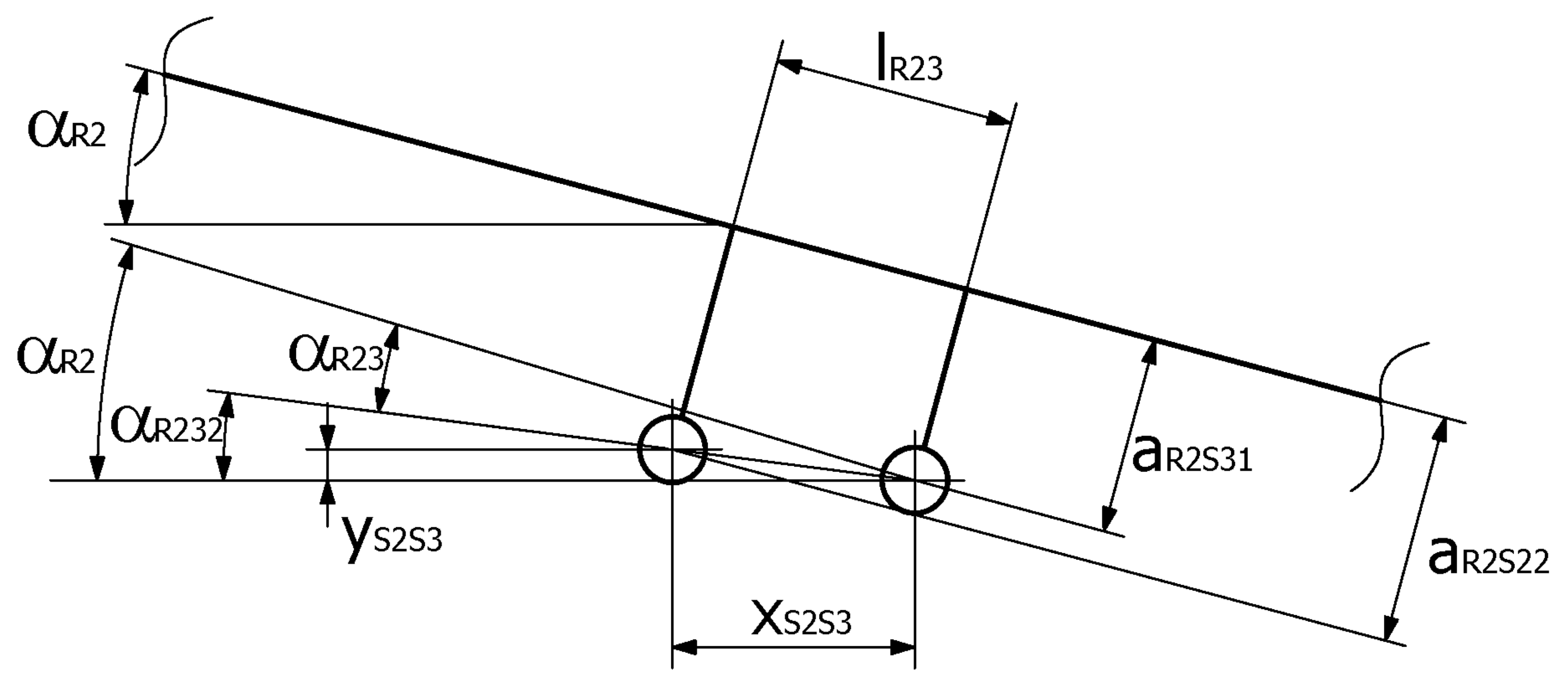
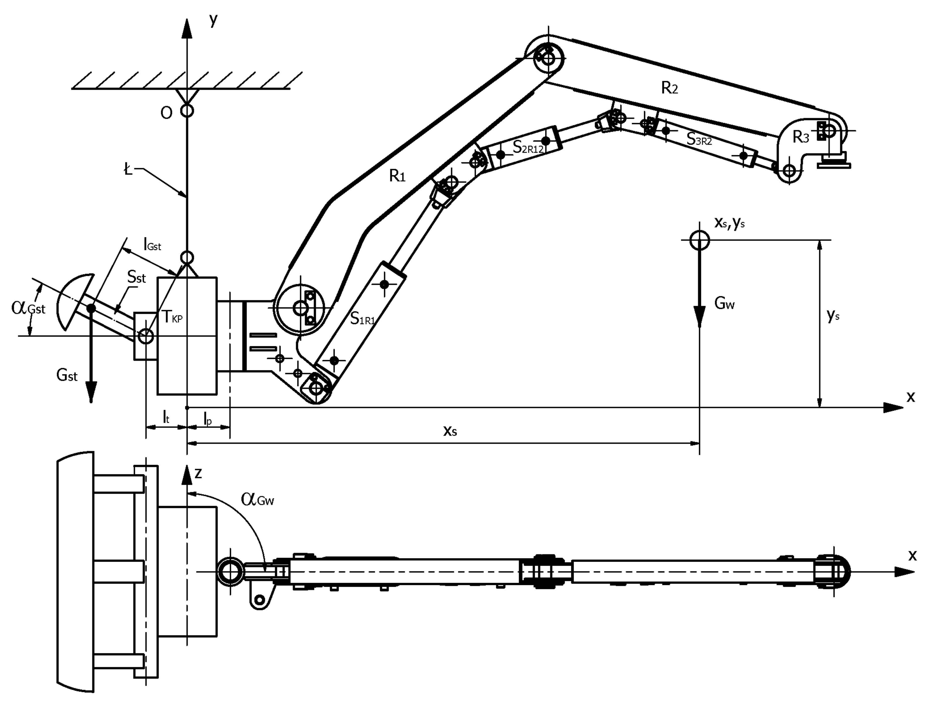
2. Analytical Model of the Manipulator and Methodology for Determining Its Stability

As mentioned before, the aim of this article was to determine the counterweight for the boom in the transport position. Therefore, the boom model shown in Figure 5 was adapted, with the boom elements being marked in Figure 6 and Figure 7.
Based on the analytical model (Figure 7), the structure and kinematics of the R1 arm were considered (Figure 5 and Figure 8). Bearing in mind the diagram (Figure 8), the dependencies that allowed one to describe the quantities that were important for the assessment of the arm’s stability as a function of the construction parameters were determined.
α R 1 = α R 11 + α R 12
α R 11 = a r c t g a R 1 S 12 l R 1 S
α R 12 = arccos a S 1 a R 1 2 + a R 1 S 11 2 + l R 1 S   ·   cos α R 11 1 2 l S 1 2 2   ·   l R 1 S   ·   cos α R 11 1   ·   a S 1 a R 1 2 + a R 1 S 11 2   a r c t g   a R 1 S 11 a S 1 a R 1
α S 1 = 90 ° + a r c t g a S 1 a R 1 a R 1 S 11 arccos a R 1 S 11 2 + a S 1 a R 1 2 l R 1 S 2   ·   cos α R 11 1 + l S 1 2 2   ·     l S 1   ·   a S 1 a R 1 2 + a R 1 S 11 2
H R 1 = a S O + a R 1 S 11 + l R 1 · sin α R 1
l W Z 1 = 0.5 · d + a R 1 + l R 1 · cos α R 1
The same was done for the R2 arm, whose computational diagram is presented in Figure 9.
α R 21 = a r c t g a R 2 S 22 l R 2 l R 2 S   + l R 23
α R 10 = a r c t g a R 1 S 21 l R 1 l R 1 S + l R 12
A = l R 2 l R 2 S + l R 23 cos α R 21
B = l R 1 l R 1 S + l R 12 cos α R 10
α R 1 R 2 = arccos A 2 + B 2 l S 2 2 2   ·   A   ·   B
α R 2 = 180 ° α R 21 + α R 10 + α R 1 + α R 1 R 2
α S 2 = α R 10 + α R 1 α R 1 S 1
α R 1 S 1 = arccos B 2 + l S 2 2 A 2 2   ·   l S 2   · B
H R 2 = H R 1 l R 2 · sin α R 2
l W Z 2 = l R 2 · cos α R 2
l S 1 = l S 1 m i n + Δ S S 1
l S 2 = l S 2 m i n + Δ S S 2
l S 3 = l S 3 m i n + Δ S S 3
l W Z = l W Z 1 + l W Z 2
The computational diagram of the R2 arm and more specifically its end, consisting of a gripping part that is moved by the S3 actuator, is presented in Figure 10.
α R 22 = a r c t g a R 2 S 31 l R 2 S
α R 2 S 31 = arccos l S 3 2 + l R 2 S   ·   cos α R 22 1 2 a R 2 S 32 2 2   ·   l S 3 ·   l R 2 S   ·   cos α R 22 1
α S 3 = α R 2 α R 22 + α R 2 S 31
α R 2 S 32 = arccos l R 2 S   ·   cos α R 22 1 2 + a R 2 S 32 2 l S 3 2 2   ·   l R 2 S   ·   cos α R 22 1   ·   α R 2 S 32
α R 2 S C = arccos   a R 2 S 32 2 + l R 3 2 l a R 3   2   ·   a R 2 S 32   ·   l R 3
α l R 3 = α R 2 S C 90 α R 2 S 32 + ( α R 2 α R 22 )
l R 3 X = l R 3 · sin α l R 3
l R 3 Y = l R 3 · cos α l R 3
Based on the above dependencies, it is possible to determine the location of the center of mass (xs, ys) for the boom system. The boom diagram is shown in Figure 11, whereas Figure 12 and Figure 13 show the diagrams that provided a basis for determining the missing parameters related to the installation of the S1, S2 and S3 actuators (lR12, lR23).
G W = G S 1 + G R 1 + G S 2 + G R 2 + G S 3 + G M + G U
where:
GW—resultant mass (weight), kg
GS1—mass (weight) of the first actuator, kg
GR1—mass (weight) of the first arm, kg
GS2—mass (weight) of the second actuator, kg
GR2—mass (weight) of the second arm, kg
GS3—mass (weight) of the third actuator, kg
GM—mass (weight) of the gripping part, kg
GU—useful mass (weight) (support arch), kg.
l G S 1 = 0.5 · d + a S 1 + x G S 1 · cos α S 1 + l p
l G R 1 = 0.5 · d + a R 1 + x G R 1 · cos α R 1 + l p
l G S 2 = 0.5 · d + a S 1 + x G S 2 · cos α S 2 + l p + x S 1 S 2 + l S 1 · cos α S 1
l G R 2 = x G R 2 · cos α R 2 + l p + l W Z 1
α R 12 P = a r c t g a R 1 S 21 a R 1 S 12 l R 12
α R 121 = α R 12 P α R 1
Δ l R 12 = l R 12 · cos α R 12 1
x S 1 S 2 = Δ l R 12 · cos α R 121
y S 1 S 2 = Δ l R 12 · sin α R 121
α R 23 = a r c t g a R 2 S 22 a R 2 S 31 l R 23
α R 232 = α R 2 α R 23
Δ l R 23 = l R 23 · cos α R 23 1
x S 2 S 3 = Δ l R 23 · cos α R 232
y S 2 S 3 = Δ l R 23 · sin α R 232
l G S 3 = 0.5 · d + a S 1 + l p + l S 1 · cos α S 1 + x S 1 S 2 + l S 2 · cos α S 2 + x S 2 S 3 + x G S 3 · cos α S 3  
x s = G S 1 ·   l G S 1 + G R 1 ·   l G R 1 + G S 2 ·   l G S 2 + G R 2 ·   l G R 2 + G S 3 ·   l G S 3 +   G M + G U ·   ( l W Z + l R 3 X ) G S 1 + G R 1 + G S 2 + G R 2 + G S 3 + G M + G U
h G S 1 = a S 0 + x G S 1 · sin α S 1
h G R 1 = a S 0 + a R 1 S 11 + x G R 1 · sin α R 1
h G S 2 = a S 0 + l S 1 · sin α S 1 + y S 1 S 2 + x G S 2 · sin α S 2
h G R 2 = H R 1 x G R 2 · sin α R 2
h G S 3 = a S 0 + l S 1 · sin α S 1 + y S 1 S 2 + l S 2 · sin α S 2 + y S 2 S 3 x G S 3 · sin α S 3
h G M U = H R 2 l R 3 Y
y s = G S 1 ·   h G S 1 + G R 1 ·   h G R 1 + G S 2 ·   h G S 2 + G R 2 ·   h G R 2 + G S 3 ·   h G S 3 +   G M + G U   ·   h G M U G S 1 + G R 1 + G S 2 + G R 2 + G S 3 + G M + G U
The location of the center of the entire boom (xs, ys) and its resultant mass Gw allows one to determine the counterbalance weight Gst (stabilizing foot) for the variant of the manipulator’s ride with the support arches. In such a case, it is required for the stabilizing foot not to be in contact with the already installed arch or arches of the support (Figure 14).
G W ·   x S t = G S t ·   l G S t t
l G S t t = l G S t · cos α G S t + l t
where:
GSt—mass (weight) of the stabilizing foot, kg
lGst—length of the arm of the stabilizing foot, m
For the transport position, the value of αGW cannot be greater than 30°, and then:
x S t = x S · sin α G W
Therefore, taking into account the dependencies of Equations (53)–(55), we obtain the following Equation (56), where:
G S t = G W   ·   x S t l G S t t = G W · x S   ·   sin α G W l G S t   ·   cos α G S t + l t
It is equally important to determine the load on the trolleys of the transport beam (points A and B), a simplified diagram of which is shown in Figure 15. Then, the beam is loaded with an additional mass (weight) with the Gz hydraulic power unit and Gn drive.
l 1 + l 2 + l 3 + l 4 = 1 P iz = 0 R AZ = 0 P iy = 0 G z G n G st + R BY G w + R AY = 0
RAY = Gz + Gn + Gst + Gw − RBy
∑MiA = 0 → – (Gz + Gn) · l1 – Gst · (l1+ l2) + RBY · (l1 + l2 + l3) – Gw · (l1 + l2 + l3 + l4)
RBy = [(Gz + Gn) · l1 + Gst · (l1+ l2) + Gw · (l1 + l2 + l3 + l4)] · (l1 + l2 + l3) −1

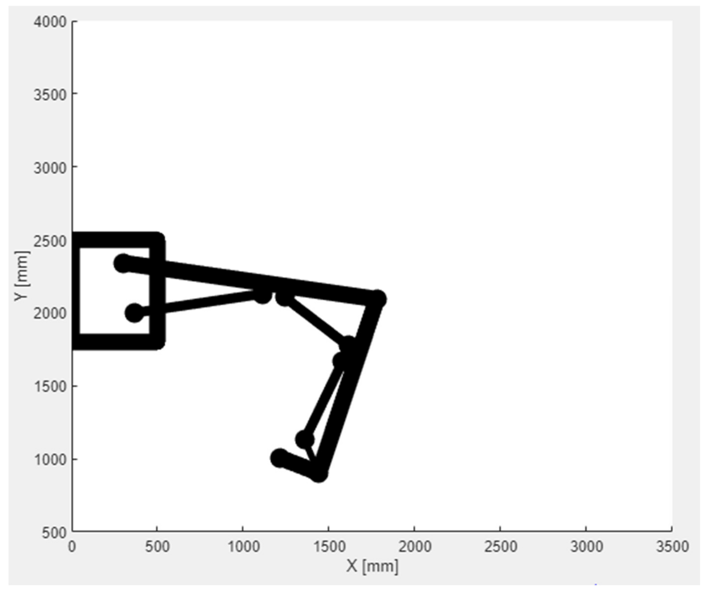
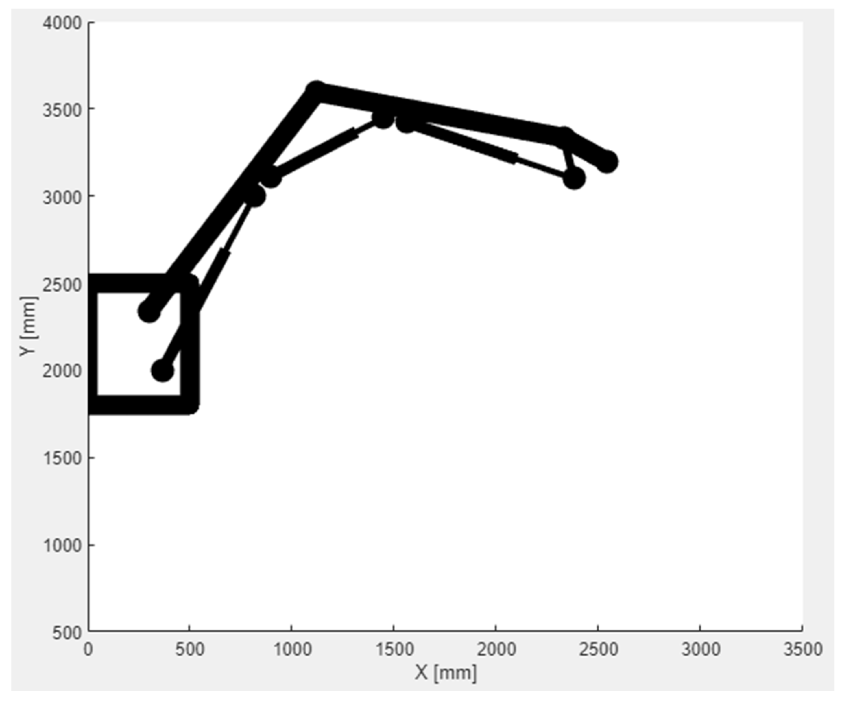
3. Calculation Results and Their Analysis

The previously described manipulator model, especially the one dedicated to the transport and assembly of the arch support, was used to develop a preliminary design and, next, a basic design and technical documentation used to create a real object (Figure 16). At the same time, as previously mentioned, data (design parameters) was obtained on the basis of the technical documentation so as to determine the manipulator’s stability, especially in the transport position (no contact of the stabilizing foot with the excavation sidewall or with the support elements). It is then important to determine the counterbalance weight, so that the manipulator can move along the excavation axis without the stabilizing foot coming into contact with the sidewall, in the case of movement without or with a load (useful weight of up to 400 kg). Of course, before the MZM-T was used in a tunnel, the results of the counterweight calculations were verified on a test stand, using specialized software (Figure 17).
The construction and mass parameters of the manipulator obtained on the basis of the technical documentation made it possible to carry out a simulation that enabled the determination of its movement trajectory and stability [19]. It was assumed that the manipulator would be suspended 4 m from the floor (aso), on the left side of the excavation (Figure 16). For such a system, the movement trajectory of the manipulator tip was determined for the minimum and maximum extensions of the actuators (Figure 18 and Figure 19). It turned out that the manipulator movement capabilities determined analytically were consistent with the research carried out on the test stand, which allowed the support arches (usable weight of up to 440 kg) to be effectively moved to the face, i.e., in front of the roadheader. This eliminated the previous process, where the elements of support arches were provided manually. At the same time, the stability of the boom-counterweight system was determined analytically for the arch transport phase, so that the stabilizing foot did not come into contact with the support. This case was considered in the system of the support, stabilizing the foot (lGST, αGST) and boom, with a maximum rotation of up to 15° and a load of up to 5 kN. As before, there was no contact between the stabilizing foot and the support, i.e., the model was consistent with the real object (test stand).

4. Conclusions

The aim of developing this manipulator model for supporting assembly works in mining excavations was to describe its basic functions (kinematics, stability) in an analytical way. The model and the calculation results were finally verified in an excavation of a hard coal mine, where the movement capabilities of the manipulator were tested (Figure 20). Given that the design, documentation and working assumptions have been fulfilled, the manipulator can be recommended for practical use in underground workings, and the model and software can be used for design purposes.

Author Contributions

Conceptualization, K.K., K.M. and T.W.; Data curation, W.H.; Formal analysis, K.K. and R.K.; Funding acquisition, K.K.; Investigation, P.R.; Methodology, K.K.; Project administration, K.M.; Resources, A.K.; Software, T.W. and R.K.; Supervision, K.K.; Validation, R.K. and P.R.; Visualization, T.W.; Writing—original draft, K.K., T.W. and K.M.; Writing—review & editing, K.M. All authors have read and agreed to the published version of the manuscript.

Funding

Works financed by the AGH University of Science and Technology.

Institutional Review Board Statement

Not applicable.

Informed Consent Statement

Not applicable.

Data Availability Statement

Data presented in the article are original and not inappropriately selected, manipulated, enhanced, or fabricated.

Conflicts of Interest

The authors declare no conflict of interest.

References

  1. Cao, J.; Zhang, N.; Wang, S.; Qian, D.; Xie, Z. Physical model test study on support of super pre-stressed anchor in the mining engineering. Eng. Fail. Anal. 2020, 118, 104833. [Google Scholar] [CrossRef]
  2. Zhu, W.; Xu, J.; Li, Y. Mechanism of the dynamic pressure caused by the instability of upper chamber coal pillars in Shendong coalfield, China. Geosci. J. 2017, 21, 729–741. [Google Scholar] [CrossRef]
  3. Xu, Y.; Pan, K.; Zhang, H. Investigation of key techniques on floor roadway support under the impacts of superimposed mining: Theoretical analysis and field study. Environ. Earth Sci. 2019, 78, 436. [Google Scholar] [CrossRef]
  4. Małkowski, P.; Ostrowski, Ł.; Bednarek, Ł. The Effect of Selected Factors on Floor Upheaval in Roadways—In Situ Testing. Energies 2020, 13, 5686. [Google Scholar] [CrossRef]
  5. Yuan, H.H.; Shan, R.L.; Su, X.G. Deformation characteristics and stability control of a gateroad in fully mechanized mining with large mining height. Arab. J. Geosci. 2018, 11, 767. [Google Scholar] [CrossRef]
  6. Mu, W.; Li, L.; Chen, D.; Wang, S.; Xiao, F. Long-term deformation and control structure of rheological tunnels based on numerical simulation and on-site monitoring. Eng. Fail. Anal. 2020, 118, 104928. [Google Scholar] [CrossRef]
  7. Tsesarsky, M.; Hatzor, Y. Tunnel roof deflection in blocky rock masses as a function of joint spacing and friction—A parametric study using discontinuous deformation analysis (DDA). Tunn. Undergr. Space Technol. 2006, 21, 29–45. [Google Scholar] [CrossRef]
  8. Bednarek, Ł.; Majcherczyk, T. An analysis of rock mass characteristics which influence the choice of support. Geomech. Eng. 2020, 21, 371–377. [Google Scholar] [CrossRef]
  9. Cai, M.; Champaigne, D.; Coulombe, J.; Challagulla, K. Development of two new rockbolts for safe and rapid tunneling in burst-prone ground. Tunn. Undergr. Space Technol. 2019, 91, 103010. [Google Scholar] [CrossRef]
  10. Wang, Q.; Luan, Y.; Jiang, B.; Li, S.; He, M.; Sun, H.; Qin, Q.; Lu, W. Study on key technology of tunnel fabricated arch and its mechanical mechanism in the mechanized construction. Tunn. Undergr. Space Technol. 2019, 83, 187–194. [Google Scholar] [CrossRef]
  11. Xue, G.; Cheng, J.; Guan, J.; Chai, J.; Zhang, G.; Hao, X.; Wu, M. The method for determining working resistance of advance support bracket in deep fully mechanized roadway based on Flac3D. Adv. Mech. Eng. 2018, 10, 6. [Google Scholar] [CrossRef]
  12. Wu, K.; Shao, Z.; Qin, S.; Wei, W.; Chu, Z. A critical review on the performance of yielding supports in squeezing tunnels. Tunn. Undergr. Space Technol. 2021, 115, 103815. [Google Scholar] [CrossRef]
  13. Rotkegel, M.; Szot, Ł.; Fabich, S. The analysis of selected methods of the yielding of a circular arch support made of V profiles. Arch. Min. Sci. 2020, 65, 531–550. [Google Scholar]
  14. Horyl, P.; Snuparek, R.; Marsalek, P.; Pacześniowski, K. Simulation of Laboratory Tests of Steel Arch Support. Arch. Min. Sci. 2017, 62, 163–176. [Google Scholar] [CrossRef] [Green Version]
  15. Nowak, P.; Kilan, Ł. Sandvik experiences with remote controlled machinery. Min. Inform. Autom. Electr. Eng. 2019, 2, 45–58. [Google Scholar] [CrossRef]
  16. Korski, J. The efficiency of a bolter miner-requirements and constraints. Min. Inform. Autom. Electr. Eng. 2020, 1, 37–44. [Google Scholar] [CrossRef]
  17. Pytlik, A. Tests of steel arch and rock bolt support resistance to static and dynamic loading induced by suspended monorail transportation. Studia Geotech. Mech. 2019, 41, 81–92. [Google Scholar] [CrossRef] [Green Version]
  18. Krauze, K.; Bołoz, Ł.; Mucha, K.; Wydro, T. The mechanized supporting system in tunnelling operations. Tunn. Undergr. Space Technol. 2021, 113, 103929. [Google Scholar] [CrossRef]
  19. Krauze, K.; Mucha, K.; Wydro, T. Ocena Stateczności Górniczego Manipulatora Transportowo-Montażowego w Różnych Fazach Jego Pracy, a Szczególnie w Czasie Transportu Obudowy do Przodka Wyrobiska Korytarzoweg. The Report from re-Search Conducted in the Department of Machinery Engineering and Transport AGH UST 2020, Kraków, Poland. 2020. unpublished. (In Polish) [Google Scholar]
  20. Krauze, K.; Mucha, K.; Wydro, T.; Kutnik, A.; Hałas, W.; Ruda, P.; Osowski, D. Operational Tests of a Modular Installation and Transport Assembly of Steel Arch Support in Underground Excavations. In Multidisciplinary Aspects of Production Engineering—MAPE; Sitko, J., Ed.; De Gruyter: Warsaw, Poland, 2021; Volume 4, p. 1. [Google Scholar] [CrossRef]
  21. GTA Roadway Support Machines. Available online: https://www.gta.eu/en/ (accessed on 3 December 2021).
  22. Maas, M. Equipment for underground mining: Projects and new developments at Deilmann-Haniel Mining Systems GmbH. Min. Rep. 2014, 150, 223–227. [Google Scholar] [CrossRef]
Figure 1. Roadway Support Machine AMG 5000 produced by GTA [21].
Energies 15 03170 g001
Figure 2. View of the mining face of a gallery drilled with a roadheader.
Energies 15 03170 g002
Figure 3. Diagram of the MZT-M in a gallery system with the arch in the transport position: (a) side view, (b) top view: 1—boom, 2—beam, 3—support slide, 4—hydraulic power unit, 5—CHM-15 tractor, 6—control panel [19,20].
Energies 15 03170 g003
Figure 4. Diagram of the MZT-M in the transport position: 1—boom, 2—beam, 3—support slide, 4—hydraulic power unit, 5—CHM-15 tractor, 6—control panel.
Energies 15 03170 g004
Figure 5. Boom model: Pp—vertical joint, R1—first arm, R2—second arm, R3—third arm with a handle, S1R1—first arm cylinder, S2R12—second arm cylinder, S3R2—third arm cylinder.
Energies 15 03170 g005
Figure 6. Diagram of the boom with marked dimensions.
Energies 15 03170 g006
Figure 7. Analytical model of the boom for determining stability.
Energies 15 03170 g007
Figure 8. Computational diagram of the R1 arm.
Energies 15 03170 g008
Figure 9. Computational diagram of the R2 arm.
Energies 15 03170 g009
Figure 10. Computational diagram of the R2 arm with an actuator.
Energies 15 03170 g010
Figure 11. Diagram of the boom for determining the resultant of the center of mass xs and ys.
Energies 15 03170 g011
Figure 12. Diagram of the S1 and S2 actuators’ mounting.
Energies 15 03170 g012
Figure 13. Diagram of the mounting of the S2 and S3 actuators.
Energies 15 03170 g013
Figure 14. Diagram of the manipulator in the transport position.
Energies 15 03170 g014
Figure 15. Simplified diagram of the transport beam loading.
Energies 15 03170 g015
Figure 16. The MZM-T on the test stand.
Energies 15 03170 g016
Figure 17. Application page of the program for determining the manipulator’s stability.
Energies 15 03170 g017
Figure 18. Movement trajectory of the manipulator tip’s movement for the minimal extension of the actuators.
Energies 15 03170 g018
Figure 19. Movement trajectory of the manipulator tip’s movement for the maximum extension of the actuators.
Energies 15 03170 g019
Figure 20. View of the MZT-M installed in an underground excavation.
Energies 15 03170 g020
Publisher’s Note: MDPI stays neutral with regard to jurisdictional claims in published maps and institutional affiliations.

